WO2012081298A1 - ボルト継手構造 - Google Patents
ボルト継手構造 Download PDFInfo
- Publication number
- WO2012081298A1 WO2012081298A1 PCT/JP2011/073411 JP2011073411W WO2012081298A1 WO 2012081298 A1 WO2012081298 A1 WO 2012081298A1 JP 2011073411 W JP2011073411 W JP 2011073411W WO 2012081298 A1 WO2012081298 A1 WO 2012081298A1
- Authority
- WO
- WIPO (PCT)
- Prior art keywords
- coupling
- bolt
- coupled
- elastic modulus
- joint structure
- Prior art date
- Legal status (The legal status is an assumption and is not a legal conclusion. Google has not performed a legal analysis and makes no representation as to the accuracy of the status listed.)
- Ceased
Links
Images




Classifications
-
- F—MECHANICAL ENGINEERING; LIGHTING; HEATING; WEAPONS; BLASTING
- F16—ENGINEERING ELEMENTS AND UNITS; GENERAL MEASURES FOR PRODUCING AND MAINTAINING EFFECTIVE FUNCTIONING OF MACHINES OR INSTALLATIONS; THERMAL INSULATION IN GENERAL
- F16B—DEVICES FOR FASTENING OR SECURING CONSTRUCTIONAL ELEMENTS OR MACHINE PARTS TOGETHER, e.g. NAILS, BOLTS, CIRCLIPS, CLAMPS, CLIPS OR WEDGES; JOINTS OR JOINTING
- F16B5/00—Joining sheets or plates, e.g. panels, to one another or to strips or bars parallel to them
- F16B5/02—Joining sheets or plates, e.g. panels, to one another or to strips or bars parallel to them by means of fastening members using screw-thread
-
- F—MECHANICAL ENGINEERING; LIGHTING; HEATING; WEAPONS; BLASTING
- F16—ENGINEERING ELEMENTS AND UNITS; GENERAL MEASURES FOR PRODUCING AND MAINTAINING EFFECTIVE FUNCTIONING OF MACHINES OR INSTALLATIONS; THERMAL INSULATION IN GENERAL
- F16B—DEVICES FOR FASTENING OR SECURING CONSTRUCTIONAL ELEMENTS OR MACHINE PARTS TOGETHER, e.g. NAILS, BOLTS, CIRCLIPS, CLAMPS, CLIPS OR WEDGES; JOINTS OR JOINTING
- F16B31/00—Screwed connections specially modified in view of tensile load; Break-bolts
- F16B31/06—Screwed connections specially modified in view of tensile load; Break-bolts having regard to possibility of fatigue rupture
-
- B—PERFORMING OPERATIONS; TRANSPORTING
- B64—AIRCRAFT; AVIATION; COSMONAUTICS
- B64C—AEROPLANES; HELICOPTERS
- B64C1/00—Fuselages; Constructional features common to fuselages, wings, stabilising surfaces or the like
- B64C1/06—Frames; Stringers; Longerons ; Fuselage sections
Definitions
- the present invention relates to a bolted joint structure that is suitable for use in a connecting portion that is required to be light in weight and strictly required to have a bonding strength, such as a connection of a wing panel portion of an aircraft to a fuselage portion.
- a bolt joint in which a plurality of bolts are arranged in the load application direction is used as a coupling means.
- a plurality of bolts share the load applied to the joint.
- Patent Document 1 discloses that such a bolt joint is used for coupling an aircraft wing panel or the like.
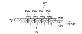
- FIG. 7 shows a conventional bolt joint structure using a plurality of bolts.
- the bolt joint structure 100 includes two coupled plate materials 102a and 102b, and a plurality (four in FIG. 7) of coupling bolts 104a to 104d are arranged along the direction in which the tensile load F acts. ing.
- the coupling bolts 104b and 104c disposed on the center side and the coupling bolts 104a and 104d disposed on the end side are coupled plate materials that transmit a load applied to the coupling portion to the coupling portion.
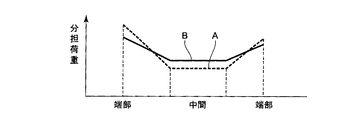
- the end side bolt has a larger shared load. This state is indicated by a load line A in FIG.
- the joint portion of the member to be joined is made of a composite material
- the composite material has a smaller ductility than a metal, so that the shared load of the end-side bolt tends to increase. Therefore, even if the number of bolts that join the joints is increased, the load applied to the joints cannot be increased.
- this bolted joint structure 110 is such that the plate thicknesses of the plate members 102a and 102b to be coupled at the coupling portion are made thinner toward the end side.
- plate materials 102a and 102b around each coupling bolt can be made small, so that it goes to an end side. It has been found that by reducing the modulus of elasticity, the rigidity of the member to be coupled can be reduced, so that the shared load of each coupling bolt can be averaged as compared with the prior art.
- the bolt joint structure 110 may not satisfy other design criteria such as the strength surface of the coupled plate material by reducing the plate thickness of the end side portions of the coupled plate materials 102a and 102b.
- the shape becomes complicated and the number of processing steps of the joint portion increases.
- the plate to be bonded is a composite material
- the composite material is composed of a large number of thin film sheets. Therefore, in order to change the thickness of the composite material, it is necessary to reduce the number of stacks constituting the composite material. There is. This further complicates processing, and there is a possibility that the symmetry of strength and the like cannot be maintained by changing the thickness of the coupling portion.
- the present inventors decided to decrease the width dimension of the coupled plate materials 102a and 102b toward the end side. As a result, it has been found that the elastic modulus of the member to be coupled can be decreased toward the end side, and the shared load of each coupling bolt can be similarly averaged. However, this bolted joint structure may also become an obstacle to satisfying design standards such as strength.
- the present invention provides a bolted joint structure that averages the shared load of each coupling bolt at the coupling portion of the coupled member, satisfies the design conditions of the coupling portion, and does not complicate processing. It aims to be realized.
- a bolted joint structure is a bolted joint formed by arranging a plurality of coupling bolts in a row along the load application direction at a coupling portion of a member to be coupled and coupling the coupling portions.
- the material of the coupling part or the material of the transmission member that transmits the load applied to the coupling part to the coupling bolt is made of a material having a smaller elastic modulus as the coupling bolt is arranged on the end side. In this configuration, the shared load to be added is averaged.
- the elastic modulus of the material of the connecting member of the member to be coupled or the material of the transmission member that uses the load applied to the joint as a coupling bolt is changed by each coupling bolt. That is, the surrounding area of the connecting bolt disposed on the end side is made of a material having a low elastic modulus, and the rigidity of the surrounding area is reduced. Thereby, the shared load of the end side bolt is reduced.
- the shared load of each connecting bolt can be averaged, the load that can be transmitted by the connecting portion can be increased in proportion to the number of connecting bolts. Further, since the shared load of the coupling bolt can be averaged regardless of the shape of the coupling portion, no extra processing is required for the coupling portion.
- the member to be joined is a composite material
- the type or content of the reinforcing fiber contained in the base material of the joint is changed along the load application direction, and the elastic modulus of the joint is changed in the load application direction. It is good to comprise so that it may change along. Thereby, the property that the elastic modulus continuously changes along the load application direction can be easily imparted at the time of manufacturing the composite material. Therefore, it becomes easy to form a coupling portion applicable to the bolt joint structure of the present invention.
- the transmission member may be a reinforcing plate interposed between a coupled member of a coupling portion and the coupling bolt.
- the transmission member is a sleeve interposed between the coupled member of the coupling portion and the coupling bolt, and the coupling bolt disposed on the end side of the coupled member has an elastic modulus higher than that of the coupled member.
- a small sleeve may be attached. In this way, by attaching a sleeve having a small elastic modulus only to the end-side bolt, the shared load of the end-side bolt can be reduced. For this reason, it is possible to use a coupled member that does not consider the elastic modulus, and the need for the reinforcing plate is eliminated, further simplifying the bolt joint structure and reducing the cost.
- a sleeve having a smaller elastic modulus may be attached to the coupling bolt arranged on the end side of the coupled member.
- the material of the coupling portion or the The material of the transmission member that transmits the load applied to the coupling part to the coupling bolt is made of a material having a smaller elastic modulus as the coupling bolt arranged at the end side, and the shared load applied to each coupling bolt is averaged Since it comprised so, the shared load of a coupling bolt can be averaged irrespective of the shape of the coupling
- FIG. 1 is a diagram schematically showing a bolted joint structure 10 according to the present embodiment.
- bonded together are comprised with the composite material.
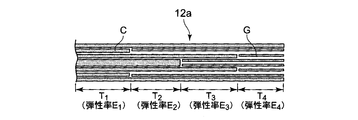
- the coupling portion 14 of the coupled plate members 12a and 12b is composed of four regions T 1 to T 4 having different elastic moduli from the inner side to the end side of the coupled member.
- the elastic modulus of these regions has a relationship of elastic modulus E 1 (region T 1 )> elastic modulus E 2 (region T 2 )> elastic modulus E 3 (region T 3 )> elastic modulus E 4 (region T 4 ). .
- the reinforcing material of the composite material that constitutes the coupled plate material 12a is composed of two types of fibers C and G.
- the fiber C is indicated by a very thick line
- the fiber G is indicated by a thick line thinner than the fiber C.
- the relationship between the elastic modulus of the fiber C and the fiber G is a relationship of fiber C> fiber G.
- the fiber C is a carbon fiber
- the fiber G is a glass fiber.
- the fibers C and D are impregnated with a resin or metal as a base material.
- the coupled member 12b is also manufactured by the same method as the coupled member 12a.
- the to-be-bonded plates 12a or 12b may be manufactured by separately forming a plurality of thin film sheets made of a fiber and a base material, and then bonding these thin film sheets together, or by eliminating the bonding process from the beginning. You may manufacture with the plate-shaped body which has the thickness of a to-be-bonded board
- One coupling bolt 16a to 16d is arranged for each region T 1 to T 4 in the coupling portion 14 of the coupled plate materials 12a and 12b manufactured as described above, and the coupling portion 14 is coupled with the coupling bolt.
- a tensile load F is applied to the coupling portion 14.
- a region having a smaller elastic modulus is formed toward the end side of the coupled plate members 12a and 12b. Therefore, the rigidity of the coupled plate members 12a and 12b is decreased toward the end side. ing. Therefore, the shared load of the connecting bolt arranged on the end side can be reduced. That is, the load applied to each connecting bolt is as shown by a load line B in FIG.
- the present invention can be applied to a joint portion that requires strict joint strength, such as a joint portion of an aircraft wing or fuselage.
- a composite material is formed by laminating and bonding a large number of thin film sheets consisting of a reinforcing member and a base material, it is difficult to change the plate thickness, and when the plate thickness is changed, strength symmetry is maintained. It becomes difficult.
- plate materials 12a and 12b are composite materials, it becomes easy to form the area
- the reinforcing plate 28 is used for the coupling portion 24.
- the coupled plate materials 22a and 22b are composite materials, but the composite materials are not changed in elastic modulus along the load application direction as in the first embodiment.
- Two reinforcing plates 28 are respectively interposed between the coupled plate material 22a and the coupling bolts 26a to 26d, and between the coupled plate materials 22a and 22b and the coupling bolts.
- the reinforcing plate 28 is made of a composite material, and is manufactured by the same method as the coupled plate materials 12a and 12b of the first embodiment shown in FIG. That is, it is composed of four regions T 1 to T 4 having different elastic moduli by changing the type and content ratio of the fibers that serve as reinforcing materials in the direction in which the tensile load F is applied.
- the elastic modulus of these regions has a relationship of elastic modulus E 1 (region T 1 )> elastic modulus E 2 (region T 2 )> elastic modulus E 3 (region T 3 )> elastic modulus E 4 (region T 4 ). .
- the two reinforcing plates 28 having such a structure the region is an elastic modulus smaller T 4 is arranged on an end side of the coupling plate 22a, 22b, the area T 1 is greater modulus of elasticity is disposed on the inner side.
- a tensile load F is transmitted to each of the coupling bolts 26a to 26d from the coupled plate materials 22a and 22b via the reinforcing plate 28.
- the end-side coupling bolt having a large shared load can reduce the shared load. That is, the load applied to each of the coupling bolts 26a to 26d of the present embodiment is as shown by the load line B in FIG.
- the bolted joint structure 20 of the present embodiment in addition to the operational effects obtained in the first embodiment, it is not necessary to process the composite material itself that constitutes the joined plate materials 22a and 22b, so that the manufacture is easy. There is an advantage of becoming.
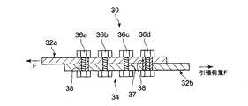
- the bolt joint structure 30 of the present embodiment includes, among the four coupling bolts 36a to 36d provided in the coupling portion 34, between the screw portions 37 of the end side bolts 36a and 36d and the coupled plate materials 32a and 32b.
- a sleeve 38 is interposed.
- a composite material that does not change the elastic modulus is used for the coupled plate materials 32a and 32b of the present embodiment.
- the sleeve 38 is made of a material having an elastic modulus smaller than the elastic modulus of the coupled plate materials 32a and 32b.
- the tensile load F is transmitted to the end side bolts 36 a and 36 d through the sleeve 38. Therefore, the shared load of the end side bolts 36a and 36d is reduced as shown by the load line B in FIG. 3, and the shared load applied to each of the coupling bolts 36a to 36d is averaged.
- the coupled plate members 32a and 32b do not need to change the elastic modulus, and may be ordinary composite materials. Further, it is not necessary to use the reinforcing plate 28 whose elastic modulus has changed as in the second embodiment. Since the sleeve 38 having a smaller elastic modulus than that of the coupled plate materials 32a and 32b only needs to be interposed between the end-side bolts 36a and 36d, the processing is easiest as compared with the first and second embodiments. .
- the sleeve 38 is attached to the end bolts 36a and 36d. Instead, the sleeve is attached not only to the end bolts 36a and 36d but also to the inner bolts 36b and 36c.
- the elastic modulus of the sleeves of the inner bolts 36b and 36c may be made of a material larger than the elastic modulus of the sleeve 28 of the end-side bolts 36a and 36d. This also makes it possible to average the shared load of each connecting bolt.
- the shared load of each coupling bolt can be averaged by a simple and low-cost means, so that the coupling strength is proportional to the number of bolts. It is suitable for the connection between a wing member and a fuselage part of an aircraft that is required to be lightweight and have a strict coupling strength.
Landscapes
- Engineering & Computer Science (AREA)
- General Engineering & Computer Science (AREA)
- Mechanical Engineering (AREA)
- Connection Of Plates (AREA)
Abstract
Description
特許文献1には、こうしたボルト継手を航空機の翼パネル等の結合に用いることが開示されている。
ボルト継手構造100では、中央側に配置された結合ボルト104b及び104cと、端側に配置された結合ボルト104a及び104dとでは、結合部に付加される荷重を結合部に伝達する被結合板材の微小なたわみ量の違いにより、一般的に、端側ボルトのほうが分担荷重が大きくなる。この状態を図3の荷重線Aで示す。
本発明の第1実施形態を図1~図3に基づいて説明する。図1は、本実施形態に係るボルト継手構造10を模式的に示す図である。図1のボルト継手構造10において、互いに結合される被結合板材12a及び12bは複合材料で構成されている。被結合板材12a、12bの結合部14は、夫々被結合部材の内側から端側に向かって、弾性率が異なる4つの領域T1~T4で構成されている。これら領域の弾性率は、弾性率E1(領域T1)>弾性率E2(領域T2)>弾性率E3(領域T3)>弾性率E4(領域T4)の関係にある。
被結合板材12a又は12bは、夫々、繊維と母材からなる複数の薄膜シートを別々に形成した後、これら薄膜シートを互いに貼り合わせて製造してもよく、あるいは貼り合わせ工程をなくし、始めから被結合板材の厚さをもつ板状体で製造してもよい。
次に、本発明の第2実施形態を図4及び図5により説明する。本実施形態のボルト継手構造20は、結合部24に補強板28を用いている。被結合板材22a及び22bは複合材料であるが、この複合材料は、前記第1実施形態のように荷重付加方向に沿って弾性率を変えたものではない。2枚の補強板28が、夫々被結合板材22aと各結合ボルト26a~dとの間、及び被結合板材22a、22bと各結合ボルト間に介在されている。
本発明の第3実施形態を図6により説明する。本実施形態のボルト継手構造30は、結合部34に設けられる4個の結合ボルト36a~dのうち、端側ボルト36a及び36dのネジ部37と、被結合板材32a、32bとの間に、スリーブ38を介装したものである。本実施形態の被結合板材32a、32bは、前記第2実施形態と同様に、弾性率を変えない複合材料を用いている。
Claims (5)
- 被結合部材の結合部に、荷重付加方向に沿って複数の結合ボルトを列状に配置し該結合部を結合してなるボルト継手構造において、
前記結合部の材質又は該結合部に付加される荷重を前記結合ボルトに伝達する伝達部材の材質を、被結合部材の端側に配置された結合ボルトほど弾性率が小さい材質で構成し、各結合ボルトに付加される分担荷重を平均化させるように構成したことを特徴とするボルト継手構造。 - 前記被結合部材が複合材料であり、結合部の母材中に含まれる強化繊維の種類又は含有量を荷重付加方向に沿って変え、該結合部の弾性率を荷重付加方向に沿って変化させるように構成したことを特徴とする請求項1に記載のボルト継手構造。
- 前記伝達部材が、結合部の被結合部材と前記結合ボルトとの間に介在された補強板であることを特徴とする請求項1又は2に記載のボルト継手構造。
- 前記伝達部材が被結合部材の結合部と前記結合ボルトとの間に介在されたスリーブであり、被結合部材の端側に配置された結合ボルトに、被結合部材より弾性率が小さいスリーブを装着してなることを特徴とする請求項1又は2に記載のボルト継手構造。
- 前記伝達部材が被結合部材の結合部と前記結合ボルトとの間に介在されたスリーブであり、被結合部材の端側に配置された結合ボルトほど弾性率が小さいスリーブを装着してなることを特徴とする請求項1又は2に記載のボルト継手構造。
Priority Applications (5)
| Application Number | Priority Date | Filing Date | Title |
|---|---|---|---|
| EP11848466.6A EP2653734B1 (en) | 2010-12-14 | 2011-10-12 | Bolt joint structure |
| US13/879,886 US9157462B2 (en) | 2010-12-14 | 2011-10-12 | Bolted joint structure |
| CA2813166A CA2813166C (en) | 2010-12-14 | 2011-10-12 | Bolt joint structure |
| BR112013010753A BR112013010753B1 (pt) | 2010-12-14 | 2011-10-12 | estrutura de junta fixada com parafuso e porca |
| CN201180049336.1A CN103154534B (zh) | 2010-12-14 | 2011-10-12 | 螺栓连接器结构 |
Applications Claiming Priority (2)
| Application Number | Priority Date | Filing Date | Title |
|---|---|---|---|
| JP2010277755A JP5693195B2 (ja) | 2010-12-14 | 2010-12-14 | ボルト継手構造 |
| JP2010-277755 | 2010-12-14 |
Publications (1)
| Publication Number | Publication Date |
|---|---|
| WO2012081298A1 true WO2012081298A1 (ja) | 2012-06-21 |
Family
ID=46244413
Family Applications (1)
| Application Number | Title | Priority Date | Filing Date |
|---|---|---|---|
| PCT/JP2011/073411 Ceased WO2012081298A1 (ja) | 2010-12-14 | 2011-10-12 | ボルト継手構造 |
Country Status (7)
| Country | Link |
|---|---|
| US (1) | US9157462B2 (ja) |
| EP (1) | EP2653734B1 (ja) |
| JP (1) | JP5693195B2 (ja) |
| CN (1) | CN103154534B (ja) |
| BR (1) | BR112013010753B1 (ja) |
| CA (1) | CA2813166C (ja) |
| WO (1) | WO2012081298A1 (ja) |
Families Citing this family (2)
| Publication number | Priority date | Publication date | Assignee | Title |
|---|---|---|---|---|
| JP6460461B2 (ja) * | 2014-12-26 | 2019-01-30 | いすゞ自動車株式会社 | 車輪速センサの取付構造 |
| JP6985192B2 (ja) * | 2018-03-19 | 2021-12-22 | 三菱重工業株式会社 | 複合材組立体 |
Citations (3)
| Publication number | Priority date | Publication date | Assignee | Title |
|---|---|---|---|---|
| JPH07156888A (ja) * | 1993-12-09 | 1995-06-20 | Mitsubishi Heavy Ind Ltd | 複合材フィッティング |
| JP2004196157A (ja) * | 2002-12-19 | 2004-07-15 | Tech Res & Dev Inst Of Japan Def Agency | 3次元複合材継ぎ手 |
| JP2009539702A (ja) * | 2006-06-13 | 2009-11-19 | ザ・ボーイング・カンパニー | 複合翼胴継手 |
Family Cites Families (12)
| Publication number | Priority date | Publication date | Assignee | Title |
|---|---|---|---|---|
| US3270410A (en) * | 1963-05-20 | 1966-09-06 | Briles Mfg | Method of prestressed fastening of materials |
| DE2736124C3 (de) * | 1977-08-11 | 1981-11-12 | Messerschmitt-Bölkow-Blohm GmbH, 8000 München | Verfahren und Wickelwerkzeug zum Herstellen eines an den Enden offenen schlaufenförmigen Kraftübertragungselements aus Faserverbundwerkstoff |
| US4579475A (en) * | 1984-01-23 | 1986-04-01 | The United States Of America As Represented By The Administrator Of The National Aeronautics And Space Administration | Optimized bolted joint |
| SU1224476A1 (ru) * | 1984-11-22 | 1986-04-15 | Московский авиационный технологический институт им.К.Э.Циолковского | Соединение деталей (его варианты) |
| US5720134A (en) * | 1997-01-02 | 1998-02-24 | Kurtz; William | Post having plastic base |
| JP2000141064A (ja) * | 1998-11-11 | 2000-05-23 | Nippon Steel Corp | 異強度材の高力ボルト摩擦接合用スプライスプレート |
| DE19925953C1 (de) * | 1999-06-08 | 2000-09-07 | Deutsch Zentr Luft & Raumfahrt | Bolzenverbindung für Faserverbundstrukturen |
| DE102004045845B3 (de) * | 2004-09-20 | 2005-12-15 | Deutsches Zentrum für Luft- und Raumfahrt e.V. | Faserverbundstruktur mit einer Bolzenverbindung und Herstellungsverfahren dafür |
| EP1861227B1 (en) * | 2005-03-23 | 2012-10-24 | Bell Helicopter Textron Inc. | Apparatus for joining members and assembly thereof |
| FR2883548B1 (fr) * | 2005-03-23 | 2007-06-15 | Airbus France Sas | Dispositif et procede d'eclissage mixte carbone-metal dissymetrique |
| GB0708333D0 (en) * | 2007-04-30 | 2007-06-06 | Airbus Uk Ltd | Composite structure |
| US8393068B2 (en) | 2007-11-06 | 2013-03-12 | The Boeing Company | Method and apparatus for assembling composite structures |
-
2010
- 2010-12-14 JP JP2010277755A patent/JP5693195B2/ja active Active
-
2011
- 2011-10-12 WO PCT/JP2011/073411 patent/WO2012081298A1/ja not_active Ceased
- 2011-10-12 CN CN201180049336.1A patent/CN103154534B/zh not_active Expired - Fee Related
- 2011-10-12 CA CA2813166A patent/CA2813166C/en not_active Expired - Fee Related
- 2011-10-12 BR BR112013010753A patent/BR112013010753B1/pt not_active IP Right Cessation
- 2011-10-12 US US13/879,886 patent/US9157462B2/en active Active
- 2011-10-12 EP EP11848466.6A patent/EP2653734B1/en not_active Not-in-force
Patent Citations (3)
| Publication number | Priority date | Publication date | Assignee | Title |
|---|---|---|---|---|
| JPH07156888A (ja) * | 1993-12-09 | 1995-06-20 | Mitsubishi Heavy Ind Ltd | 複合材フィッティング |
| JP2004196157A (ja) * | 2002-12-19 | 2004-07-15 | Tech Res & Dev Inst Of Japan Def Agency | 3次元複合材継ぎ手 |
| JP2009539702A (ja) * | 2006-06-13 | 2009-11-19 | ザ・ボーイング・カンパニー | 複合翼胴継手 |
Also Published As
| Publication number | Publication date |
|---|---|
| JP2012127387A (ja) | 2012-07-05 |
| CN103154534B (zh) | 2015-08-19 |
| CA2813166A1 (en) | 2012-06-21 |
| US20130287490A1 (en) | 2013-10-31 |
| EP2653734A1 (en) | 2013-10-23 |
| US9157462B2 (en) | 2015-10-13 |
| EP2653734A4 (en) | 2016-01-06 |
| CN103154534A (zh) | 2013-06-12 |
| JP5693195B2 (ja) | 2015-04-01 |
| BR112013010753A2 (pt) | 2016-08-09 |
| BR112013010753B1 (pt) | 2020-06-09 |
| EP2653734B1 (en) | 2018-04-18 |
| CA2813166C (en) | 2015-12-22 |
Similar Documents
| Publication | Publication Date | Title |
|---|---|---|
| US8925991B2 (en) | Reinforced frame-to-body attachment | |
| CN101873965B (zh) | 飞机机身环周接合部处的ω形加固件的拼接 | |
| US8528865B2 (en) | Connecting arrangement for joining two stiffening elements having different cross-sectional profiles for an aircraft or spacecraft, and shell component | |
| US20160311514A1 (en) | Lightweight structural panel | |
| US10399520B2 (en) | Vehicle body structure | |
| WO2004076761A1 (ja) | 梁継手装置 | |
| US10094405B2 (en) | Joint structure for composite member | |
| JPWO2013108354A1 (ja) | パネル接合構造 | |
| WO2013129122A1 (ja) | 複合材構造体、これを備えた航空機翼および航空機胴体、並びに複合材構造体の製造方法 | |
| JP5693195B2 (ja) | ボルト継手構造 | |
| CN105916673B (zh) | 复合材料构造 | |
| CN102202965B (zh) | 用于调整飞机的水平稳定器的配件 | |
| JP5466091B2 (ja) | 乗客コンベアの主枠 | |
| JP2018172927A (ja) | 柱構造体 | |
| US11339813B2 (en) | Joint structure | |
| KR101846648B1 (ko) | 접합구조를 갖는 복합재 부품 | |
| US20080286073A1 (en) | Hybrid contoured load-spreading washer | |
| JP2014118091A (ja) | 航空機用内装パネルの結合構造 | |
| US11181135B2 (en) | Composite material assembly | |
| KR101784941B1 (ko) | 연결구조체 | |
| JPH0455859B2 (ja) | ||
| CN218477566U (zh) | 一种中通道加强板 | |
| US20240246615A1 (en) | Floor structure for vehicle | |
| KR20260045106A (ko) | 고정부재가 결합된 프로파일 | |
| US10041517B2 (en) | Fastener element |
Legal Events
| Date | Code | Title | Description |
|---|---|---|---|
| WWE | Wipo information: entry into national phase |
Ref document number: 201180049336.1 Country of ref document: CN |
|
| 121 | Ep: the epo has been informed by wipo that ep was designated in this application |
Ref document number: 11848466 Country of ref document: EP Kind code of ref document: A1 |
|
| WWE | Wipo information: entry into national phase |
Ref document number: 2011848466 Country of ref document: EP |
|
| ENP | Entry into the national phase |
Ref document number: 2813166 Country of ref document: CA |
|
| WWE | Wipo information: entry into national phase |
Ref document number: 13879886 Country of ref document: US |
|
| NENP | Non-entry into the national phase |
Ref country code: DE |
|
| REG | Reference to national code |
Ref country code: BR Ref legal event code: B01A Ref document number: 112013010753 Country of ref document: BR |
|
| ENP | Entry into the national phase |
Ref document number: 112013010753 Country of ref document: BR Kind code of ref document: A2 Effective date: 20130430 |