WO2012081464A1 - NOx浄化率低下原因診断装置 - Google Patents
NOx浄化率低下原因診断装置 Download PDFInfo
- Publication number
- WO2012081464A1 WO2012081464A1 PCT/JP2011/078284 JP2011078284W WO2012081464A1 WO 2012081464 A1 WO2012081464 A1 WO 2012081464A1 JP 2011078284 W JP2011078284 W JP 2011078284W WO 2012081464 A1 WO2012081464 A1 WO 2012081464A1
- Authority
- WO
- WIPO (PCT)
- Prior art keywords
- nox purification
- failure
- exhaust pipe
- nox
- cause
- Prior art date
- Legal status (The legal status is an assumption and is not a legal conclusion. Google has not performed a legal analysis and makes no representation as to the accuracy of the status listed.)
- Ceased
Links
Images
Classifications
-
- F—MECHANICAL ENGINEERING; LIGHTING; HEATING; WEAPONS; BLASTING
- F01—MACHINES OR ENGINES IN GENERAL; ENGINE PLANTS IN GENERAL; STEAM ENGINES
- F01N—GAS-FLOW SILENCERS OR EXHAUST APPARATUS FOR MACHINES OR ENGINES IN GENERAL; GAS-FLOW SILENCERS OR EXHAUST APPARATUS FOR INTERNAL-COMBUSTION ENGINES
- F01N11/00—Monitoring or diagnostic devices for exhaust-gas treatment apparatus
-
- B—PERFORMING OPERATIONS; TRANSPORTING
- B01—PHYSICAL OR CHEMICAL PROCESSES OR APPARATUS IN GENERAL
- B01D—SEPARATION
- B01D53/00—Separation of gases or vapours; Recovering vapours of volatile solvents from gases; Chemical or biological purification of waste gases, e.g. engine exhaust gases, smoke, fumes, flue gases, aerosols
- B01D53/34—Chemical or biological purification of waste gases
- B01D53/92—Chemical or biological purification of waste gases of engine exhaust gases
- B01D53/94—Chemical or biological purification of waste gases of engine exhaust gases by catalytic processes
- B01D53/9404—Removing only nitrogen compounds
- B01D53/9409—Nitrogen oxides
-
- B—PERFORMING OPERATIONS; TRANSPORTING
- B01—PHYSICAL OR CHEMICAL PROCESSES OR APPARATUS IN GENERAL
- B01D—SEPARATION
- B01D53/00—Separation of gases or vapours; Recovering vapours of volatile solvents from gases; Chemical or biological purification of waste gases, e.g. engine exhaust gases, smoke, fumes, flue gases, aerosols
- B01D53/34—Chemical or biological purification of waste gases
- B01D53/92—Chemical or biological purification of waste gases of engine exhaust gases
- B01D53/94—Chemical or biological purification of waste gases of engine exhaust gases by catalytic processes
- B01D53/9459—Removing one or more of nitrogen oxides, carbon monoxide, or hydrocarbons by multiple successive catalytic functions; systems with more than one different function, e.g. zone coated catalysts
- B01D53/9477—Removing one or more of nitrogen oxides, carbon monoxide, or hydrocarbons by multiple successive catalytic functions; systems with more than one different function, e.g. zone coated catalysts with catalysts positioned on separate bricks, e.g. exhaust systems
-
- B—PERFORMING OPERATIONS; TRANSPORTING
- B01—PHYSICAL OR CHEMICAL PROCESSES OR APPARATUS IN GENERAL
- B01D—SEPARATION
- B01D53/00—Separation of gases or vapours; Recovering vapours of volatile solvents from gases; Chemical or biological purification of waste gases, e.g. engine exhaust gases, smoke, fumes, flue gases, aerosols
- B01D53/34—Chemical or biological purification of waste gases
- B01D53/92—Chemical or biological purification of waste gases of engine exhaust gases
- B01D53/94—Chemical or biological purification of waste gases of engine exhaust gases by catalytic processes
- B01D53/9495—Controlling the catalytic process
-
- F—MECHANICAL ENGINEERING; LIGHTING; HEATING; WEAPONS; BLASTING
- F01—MACHINES OR ENGINES IN GENERAL; ENGINE PLANTS IN GENERAL; STEAM ENGINES
- F01N—GAS-FLOW SILENCERS OR EXHAUST APPARATUS FOR MACHINES OR ENGINES IN GENERAL; GAS-FLOW SILENCERS OR EXHAUST APPARATUS FOR INTERNAL-COMBUSTION ENGINES
- F01N13/00—Exhaust or silencing apparatus characterised by constructional features
- F01N13/009—Exhaust or silencing apparatus characterised by constructional features having two or more separate purifying devices arranged in series
- F01N13/0097—Exhaust or silencing apparatus characterised by constructional features having two or more separate purifying devices arranged in series the purifying devices are arranged in a single housing
-
- F—MECHANICAL ENGINEERING; LIGHTING; HEATING; WEAPONS; BLASTING
- F01—MACHINES OR ENGINES IN GENERAL; ENGINE PLANTS IN GENERAL; STEAM ENGINES
- F01N—GAS-FLOW SILENCERS OR EXHAUST APPARATUS FOR MACHINES OR ENGINES IN GENERAL; GAS-FLOW SILENCERS OR EXHAUST APPARATUS FOR INTERNAL-COMBUSTION ENGINES
- F01N3/00—Exhaust or silencing apparatus having means for purifying, rendering innocuous, or otherwise treating exhaust
- F01N3/02—Exhaust or silencing apparatus having means for purifying, rendering innocuous, or otherwise treating exhaust for cooling, or for removing solid constituents of, exhaust
- F01N3/021—Exhaust or silencing apparatus having means for purifying, rendering innocuous, or otherwise treating exhaust for cooling, or for removing solid constituents of, exhaust by means of filters
- F01N3/033—Exhaust or silencing apparatus having means for purifying, rendering innocuous, or otherwise treating exhaust for cooling, or for removing solid constituents of, exhaust by means of filters in combination with other devices
- F01N3/035—Exhaust or silencing apparatus having means for purifying, rendering innocuous, or otherwise treating exhaust for cooling, or for removing solid constituents of, exhaust by means of filters in combination with other devices with catalytic reactors
-
- F—MECHANICAL ENGINEERING; LIGHTING; HEATING; WEAPONS; BLASTING
- F01—MACHINES OR ENGINES IN GENERAL; ENGINE PLANTS IN GENERAL; STEAM ENGINES
- F01N—GAS-FLOW SILENCERS OR EXHAUST APPARATUS FOR MACHINES OR ENGINES IN GENERAL; GAS-FLOW SILENCERS OR EXHAUST APPARATUS FOR INTERNAL-COMBUSTION ENGINES
- F01N3/00—Exhaust or silencing apparatus having means for purifying, rendering innocuous, or otherwise treating exhaust
- F01N3/08—Exhaust or silencing apparatus having means for purifying, rendering innocuous, or otherwise treating exhaust for rendering innocuous
- F01N3/0807—Exhaust or silencing apparatus having means for purifying, rendering innocuous, or otherwise treating exhaust for rendering innocuous by using absorbents or adsorbents
- F01N3/0814—Exhaust or silencing apparatus having means for purifying, rendering innocuous, or otherwise treating exhaust for rendering innocuous by using absorbents or adsorbents combined with catalytic converters, e.g. NOx absorption/storage reduction catalysts
-
- F—MECHANICAL ENGINEERING; LIGHTING; HEATING; WEAPONS; BLASTING
- F01—MACHINES OR ENGINES IN GENERAL; ENGINE PLANTS IN GENERAL; STEAM ENGINES
- F01N—GAS-FLOW SILENCERS OR EXHAUST APPARATUS FOR MACHINES OR ENGINES IN GENERAL; GAS-FLOW SILENCERS OR EXHAUST APPARATUS FOR INTERNAL-COMBUSTION ENGINES
- F01N3/00—Exhaust or silencing apparatus having means for purifying, rendering innocuous, or otherwise treating exhaust
- F01N3/08—Exhaust or silencing apparatus having means for purifying, rendering innocuous, or otherwise treating exhaust for rendering innocuous
- F01N3/0807—Exhaust or silencing apparatus having means for purifying, rendering innocuous, or otherwise treating exhaust for rendering innocuous by using absorbents or adsorbents
- F01N3/0828—Exhaust or silencing apparatus having means for purifying, rendering innocuous, or otherwise treating exhaust for rendering innocuous by using absorbents or adsorbents characterised by the absorbed or adsorbed substances
- F01N3/0842—Nitrogen oxides
-
- F—MECHANICAL ENGINEERING; LIGHTING; HEATING; WEAPONS; BLASTING
- F01—MACHINES OR ENGINES IN GENERAL; ENGINE PLANTS IN GENERAL; STEAM ENGINES
- F01N—GAS-FLOW SILENCERS OR EXHAUST APPARATUS FOR MACHINES OR ENGINES IN GENERAL; GAS-FLOW SILENCERS OR EXHAUST APPARATUS FOR INTERNAL-COMBUSTION ENGINES
- F01N3/00—Exhaust or silencing apparatus having means for purifying, rendering innocuous, or otherwise treating exhaust
- F01N3/08—Exhaust or silencing apparatus having means for purifying, rendering innocuous, or otherwise treating exhaust for rendering innocuous
- F01N3/10—Exhaust or silencing apparatus having means for purifying, rendering innocuous, or otherwise treating exhaust for rendering innocuous by thermal or catalytic conversion of noxious components of exhaust
- F01N3/105—General auxiliary catalysts, e.g. upstream or downstream of the main catalyst
- F01N3/106—Auxiliary oxidation catalysts
-
- F—MECHANICAL ENGINEERING; LIGHTING; HEATING; WEAPONS; BLASTING
- F01—MACHINES OR ENGINES IN GENERAL; ENGINE PLANTS IN GENERAL; STEAM ENGINES
- F01N—GAS-FLOW SILENCERS OR EXHAUST APPARATUS FOR MACHINES OR ENGINES IN GENERAL; GAS-FLOW SILENCERS OR EXHAUST APPARATUS FOR INTERNAL-COMBUSTION ENGINES
- F01N2550/00—Monitoring or diagnosing the deterioration of exhaust systems
- F01N2550/02—Catalytic activity of catalytic converters
-
- F—MECHANICAL ENGINEERING; LIGHTING; HEATING; WEAPONS; BLASTING
- F01—MACHINES OR ENGINES IN GENERAL; ENGINE PLANTS IN GENERAL; STEAM ENGINES
- F01N—GAS-FLOW SILENCERS OR EXHAUST APPARATUS FOR MACHINES OR ENGINES IN GENERAL; GAS-FLOW SILENCERS OR EXHAUST APPARATUS FOR INTERNAL-COMBUSTION ENGINES
- F01N2550/00—Monitoring or diagnosing the deterioration of exhaust systems
- F01N2550/03—Monitoring or diagnosing the deterioration of exhaust systems of sorbing activity of adsorbents or absorbents
-
- F—MECHANICAL ENGINEERING; LIGHTING; HEATING; WEAPONS; BLASTING
- F01—MACHINES OR ENGINES IN GENERAL; ENGINE PLANTS IN GENERAL; STEAM ENGINES
- F01N—GAS-FLOW SILENCERS OR EXHAUST APPARATUS FOR MACHINES OR ENGINES IN GENERAL; GAS-FLOW SILENCERS OR EXHAUST APPARATUS FOR INTERNAL-COMBUSTION ENGINES
- F01N2610/00—Adding substances to exhaust gases
- F01N2610/03—Adding substances to exhaust gases the substance being hydrocarbons, e.g. engine fuel
-
- F—MECHANICAL ENGINEERING; LIGHTING; HEATING; WEAPONS; BLASTING
- F01—MACHINES OR ENGINES IN GENERAL; ENGINE PLANTS IN GENERAL; STEAM ENGINES
- F01N—GAS-FLOW SILENCERS OR EXHAUST APPARATUS FOR MACHINES OR ENGINES IN GENERAL; GAS-FLOW SILENCERS OR EXHAUST APPARATUS FOR INTERNAL-COMBUSTION ENGINES
- F01N2900/00—Details of electrical control or of the monitoring of the exhaust gas treating apparatus
- F01N2900/06—Parameters used for exhaust control or diagnosing
- F01N2900/16—Parameters used for exhaust control or diagnosing said parameters being related to the exhaust apparatus, e.g. particulate filter or catalyst
- F01N2900/1631—Heat amount provided to exhaust apparatus
-
- F—MECHANICAL ENGINEERING; LIGHTING; HEATING; WEAPONS; BLASTING
- F01—MACHINES OR ENGINES IN GENERAL; ENGINE PLANTS IN GENERAL; STEAM ENGINES
- F01N—GAS-FLOW SILENCERS OR EXHAUST APPARATUS FOR MACHINES OR ENGINES IN GENERAL; GAS-FLOW SILENCERS OR EXHAUST APPARATUS FOR INTERNAL-COMBUSTION ENGINES
- F01N3/00—Exhaust or silencing apparatus having means for purifying, rendering innocuous, or otherwise treating exhaust
- F01N3/08—Exhaust or silencing apparatus having means for purifying, rendering innocuous, or otherwise treating exhaust for rendering innocuous
- F01N3/10—Exhaust or silencing apparatus having means for purifying, rendering innocuous, or otherwise treating exhaust for rendering innocuous by thermal or catalytic conversion of noxious components of exhaust
- F01N3/18—Exhaust or silencing apparatus having means for purifying, rendering innocuous, or otherwise treating exhaust for rendering innocuous by thermal or catalytic conversion of noxious components of exhaust characterised by methods of operation; Control
- F01N3/20—Exhaust or silencing apparatus having means for purifying, rendering innocuous, or otherwise treating exhaust for rendering innocuous by thermal or catalytic conversion of noxious components of exhaust characterised by methods of operation; Control specially adapted for catalytic conversion
- F01N3/206—Adding periodically or continuously substances to exhaust gases for promoting purification, e.g. catalytic material in liquid form, NOx reducing agents
- F01N3/2066—Selective catalytic reduction [SCR]
-
- Y—GENERAL TAGGING OF NEW TECHNOLOGICAL DEVELOPMENTS; GENERAL TAGGING OF CROSS-SECTIONAL TECHNOLOGIES SPANNING OVER SEVERAL SECTIONS OF THE IPC; TECHNICAL SUBJECTS COVERED BY FORMER USPC CROSS-REFERENCE ART COLLECTIONS [XRACs] AND DIGESTS
- Y02—TECHNOLOGIES OR APPLICATIONS FOR MITIGATION OR ADAPTATION AGAINST CLIMATE CHANGE
- Y02T—CLIMATE CHANGE MITIGATION TECHNOLOGIES RELATED TO TRANSPORTATION
- Y02T10/00—Road transport of goods or passengers
- Y02T10/10—Internal combustion engine [ICE] based vehicles
- Y02T10/40—Engine management systems
-
- Y—GENERAL TAGGING OF NEW TECHNOLOGICAL DEVELOPMENTS; GENERAL TAGGING OF CROSS-SECTIONAL TECHNOLOGIES SPANNING OVER SEVERAL SECTIONS OF THE IPC; TECHNICAL SUBJECTS COVERED BY FORMER USPC CROSS-REFERENCE ART COLLECTIONS [XRACs] AND DIGESTS
- Y10—TECHNICAL SUBJECTS COVERED BY FORMER USPC
- Y10T—TECHNICAL SUBJECTS COVERED BY FORMER US CLASSIFICATION
- Y10T137/00—Fluid handling
- Y10T137/8158—With indicator, register, recorder, alarm or inspection means
Definitions
- the present invention relates to a NOx purification rate lowering cause diagnosis device capable of performing self-diagnosis for specifying the cause of NOx purification rate lowering.
- De-NOx nitrogen oxide reduction
- HC-SCR hydrocarbon selective reduction catalyst device
- LNT NOx occlusion device
- NOx sensors are installed on the upstream and downstream sides of the NOx purification device, and the NOx purification rate is calculated from the ratio of the NOx concentrations detected by these NOx sensors. Can do.
- the NOx purification rate may decrease even if these members break down.
- the NOx purification rate also decreases due to failure of various members around the engine and failure of the reducing agent addition device (exhaust pipe fuel injection device). Therefore, even if the NOx purification rate decreases, it cannot be determined immediately that the NOx purification device is out of order. It is desirable to determine whether the cause of the decrease in the NOx purification rate is a failure of various members around the engine, a failure of the reducing agent addition device, or a failure of the NOx purification device.
- an object of the present invention is to provide a NOx purification rate lowering cause diagnosis device capable of solving the above-described problems and performing a self-diagnosis that identifies the cause of the NOx purification rate lowering.
- the present invention is a NOx purification rate reduction cause diagnosis device applied to an engine system having an exhaust pipe fuel injector, an oxidation catalyst device, and a NOx purification device, and when the NOx purification rate is reduced. If the error between the measured heat generation amount and the theoretical heat generation amount in the oxidation catalyst device during the exhaust pipe fuel injection is within a threshold when the exhaust pipe fuel injection is performed for diagnosis and the exhaust pipe fuel injection control unit for diagnosis, The cause of the decrease in the NOx purification rate is that the error between the NOx purification device failure identification unit that identifies a NOx purification device failure and the actual calorific value and the theoretical calorific value at the oxidation catalyst device when the exhaust pipe fuel injection is performed exceed a threshold value. In this case, the cause of the NOx purification rate reduction is provided with an oxidation catalyst device failure identification unit that identifies the oxidation catalyst device.
- the present invention exhibits the following excellent effects.
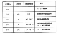
- FIG. 6 is a distribution diagram of heat generation along the exhaust pipe. It is a figure which shows the diagnostic matrix equivalent to the control procedure of FIG.
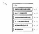
- a NOx purification rate decrease cause diagnosis apparatus 1 includes a diagnostic exhaust pipe fuel injection control unit 2 that performs exhaust pipe fuel injection for diagnosis when the NOx purification rate decreases, and an exhaust gas If the error between the measured exhaust gas air-fuel ratio and the theoretical exhaust gas air-fuel ratio when the pipe fuel injection is not performed exceeds the threshold value, the cause of the NOx purification rate decrease is the engine-side failure specifying unit 3 that specifies the engine-side failure; If the error between the measured exhaust gas air-fuel ratio and the theoretical exhaust gas air-fuel ratio at the time of exhaust pipe fuel injection exceeds the threshold, the cause of the decrease in the NOx purification rate is determined as an exhaust pipe fuel injector failure.
- the cause of the decrease in the NOx purification rate is identified as a NOx purification device failure.
- the cause of the decrease in the NOx purification rate is the oxidation that identifies the oxidation catalyst device failure.
- the specifying unit 6 and the combined fault specifying unit 7 are realized by software executed by an electronic control unit (Electronic Control Unit; hereinafter referred to as ECU). It is assumed that the ECU grasps all engine parameters (sensor detection values, calculation values, control values, etc.) necessary for controlling the engine system.
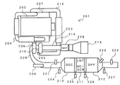
- the engine system 201 to which the NOx purification rate reduction cause diagnosis device 1 of the present invention is applied includes an exhaust gas recirculation device (ExGRt Gas Recirculation; EGR) in the exhaust manifold 203 of the engine 202.
- EGR exhaust gas recirculation
- the EGR pipe 204 is connected, and the inlet of the exhaust turbine 206 of the turbocharger 205 is connected.
- the downstream end of the EGR pipe 204 is connected to the intake manifold 207.
- An exhaust pipe 208 is connected to the outlet of the exhaust turbine 206.
- an exhaust pipe fuel injector 209 for injecting fuel into the exhaust pipe 208 in order from the upstream, an oxidation catalyst device (Diesel Oxidation Catalyst; hereinafter referred to as DOC) 210 for promoting the oxidation of the fuel and intermediate products, NOx purification device 211 such as HC-SCR, LNT, diesel particulate filter (DieselDPParticulate Filter; hereinafter referred to as DPF) 212 that collects particulate matter (Particulate Matter; PM) or catalyzed soot filter (Catalyzed Soot Filter) CSF) is installed.
- Diesel Oxidation Catalyst Diesel Oxidation Catalyst
- DPF diesel particulate filter
- PM particulate Matter
- Catalyzed Soot Filter catalyzed soot filter
- the DOC 210, the NOx purification device 211, and the DPF 212 all use a catalyst.
- the DOC 210, the NOx purification device 211, and the DPF 212 may be simply referred to as a catalyst.
- the exhaust pipe fuel injector 209 is provided for injecting light oil as fuel into the exhaust pipe 208 when the particulate matter collected by the DPF 212 is removed by combustion (DPF regeneration, PM regeneration).
- the injected fuel can be oxidized in the DOC 210, the NOx purifying device 211, the DPF 212, etc. by the intervention of the catalyst, and the exhaust gas temperature can be raised to the DPF regeneration temperature.
- exhaust pipe fuel injection can be performed for the purpose of adding hydrocarbon as a reducing agent to HC-SCR and LNT. In the present invention, exhaust pipe fuel injection is performed for diagnosis of the cause of the NOx purification rate reduction.
- the intake pipe 214 is connected to the air filter 213 that takes in air from the atmosphere, and the downstream end of the intake pipe 214 is connected to the inlet of the intake compressor 215 of the turbocharger 205.
- a high-pressure side intake pipe 216 is connected to the outlet of the intake compressor 215, and a downstream end of the high-pressure side intake pipe 216 is connected to the intake manifold 207.
- a first NOx sensor 221 that detects the engine outlet NOx concentration is installed upstream of the DOC 210 of the exhaust pipe 208, and a second NOx sensor 222 that detects the post-catalyst NOx concentration is installed downstream of the DPF 212.
- An exhaust gas ⁇ sensor 223 that detects the air-fuel ratio of exhaust gas (actually measured exhaust gas air-fuel ratio) is installed downstream of the DPF 212.
- the exhaust pipe 208 includes a first temperature sensor 224 that detects the temperature of the exhaust gas flowing into the DOC 210 upstream of the DOC 210 (DOC inlet temperature), a DOC outlet temperature (NOx purification device inlet temperature) between the DOC 210 and the NOx purification device 211.
- the third temperature sensor 226 for detecting the NOx purification device outlet temperature (DPF inlet temperature) between the NOx purification device 211 and the DPF 212.
- a four temperature sensor 227 is installed.
- An air flow sensor (Mass Airflow ⁇ ⁇ ⁇ sensor; hereinafter referred to as MAF sensor) 228 for detecting the amount of intake air is installed in the intake pipe 214.
- the first NOx sensor 221, the second NOx sensor 222, the exhaust gas ⁇ sensor 223, and the first to fourth temperature sensors 224 to 227 are separate from the self-diagnosis by the NOx purification rate decrease cause diagnosis device 1 of the present invention. It is assumed that each sensor is confirmed to be normal by the self-diagnosis of the sensor performed in the above.
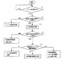
- the control procedure executed by the NOx purification rate decrease cause diagnosis device 1 is NOx purification rate decrease determination step S ⁇ b> 1 for determining whether or not the NOx purification rate is decreased, and whether or not the non-injection air-fuel ratio abnormality is determined.
- Step S2 for identifying the cause of failure when exhaust pipe fuel injection is not performed ( ⁇ diagnosis A)
- Step S3 for performing exhaust pipe fuel injection, and identifying the cause of failure when performing exhaust pipe fuel injection to determine whether the air-fuel ratio is abnormal when injection is present
- the NOx purification rate lowering cause diagnosis apparatus 1 determines whether or not the NOx purification rate lowering occurs when a predetermined determination condition is satisfied in step S1 of the NOx purification rate lowering determination.
- the determination conditions are that the exhaust gas temperature is stable and the vehicle travel is stable. If the vehicle travel is unstable, the engine state becomes a transitional state and the detection of the NOx concentration in the exhaust gas becomes unstable, so the determination of the NOx purification rate reduction is suspended.
- the NOx purification rate is obtained from the post-catalyst NOx concentration and the pre-catalyst NOx concentration.
- the engine outlet NOx concentration is used as the pre-catalyst NOx concentration
- the detected value of the first NOx sensor 221 is the engine outlet.
- NOx purification rate (1 ⁇ NOx concentration after catalyst / NOx concentration at engine outlet) ⁇ 100 (%) Is calculated by
- the engine outlet NOx concentration may be estimated from a known theoretical formula or map using engine parameters without using the first NOx sensor 221.
- the engine outlet NOx concentration and the post-catalyst NOx concentration are always detected at predetermined sampling intervals, and the NOx purification rate can be calculated in real time.
- the NOx purification rate decrease cause diagnosis device 1 determines that the NOx purification rate has decreased when the state where the NOx purification rate has become equal to or lower than a preset threshold value continues for a predetermined time or more. By this determination, the NOx purification rate reduction cause diagnosis of the present invention is substantially started.
- step S2 for specifying the cause of failure when the exhaust pipe fuel injection is not performed it is determined whether the air-fuel ratio is abnormal when there is no injection. That is, the engine-side failure specifying unit 3 calculates the theoretical exhaust gas air-fuel ratio at the installation position of the exhaust gas ⁇ sensor 223 by a known theoretical formula using the intake air amount and the fuel injection amount, and the exhaust gas ⁇ sensor 223 detects the theoretical exhaust gas air-fuel ratio. Compare with the measured exhaust gas air-fuel ratio. If the error between the actually measured exhaust gas air-fuel ratio and the theoretical exhaust gas air-fuel ratio exceeds a preset threshold value, it is abnormal. In this case, since the theoretical exhaust gas air-fuel ratio cannot be calculated correctly, the cause of the decrease in the NOx purification rate is specified as an engine-side failure.
- the engine side failure means a failure of any of the members located upstream from the exhaust pipe 208.
- the MAF sensor 228 fails, the intake air amount becomes inaccurate, so that the calculation of the theoretical exhaust gas air-fuel ratio becomes inaccurate.
- the fuel injector in the engine 202 is clogged, an error in the fuel injection amount becomes large, and the calculation of the theoretical exhaust gas air-fuel ratio becomes inaccurate.
- a diagnosis for further specifying the failure site may be performed.
- known abnormality determination information for example, sensor output voltage abnormality relating to various members such as the EGR valve, the intake throttle, the turbocharger, and the MAF sensor 228 may be used.
- step S2 If it is determined in step S2 that the error is equal to or less than the threshold value, it can be determined that the air-fuel ratio without injection is normal, and therefore there is no abnormality on the engine side, and the process proceeds to the next.
- step S3 for exhaust pipe fuel injection the diagnostic exhaust pipe fuel injection control unit 2 performs exhaust pipe fuel injection.
- Exhaust pipe fuel injection is performed with the same injection amount as during DPF regeneration.
- the operator may be prompted to perform an operation during the control procedure, and the operator may perform the operation manually.
- step S4 of specifying the cause of failure when performing exhaust pipe fuel injection it is determined whether or not the air-fuel ratio is abnormal with injection. That is, the exhaust pipe fuel injector failure identifying unit 4 uses the exhaust gas ⁇ sensor 223 according to a known theoretical formula using the exhaust gas weight exhausted from the engine 202 and the exhaust pipe fuel injection amount obtained from the intake air amount and the fuel injection amount. Is calculated and compared with the actually measured exhaust gas air-fuel ratio detected by the exhaust gas ⁇ sensor 223. If the error between the actually measured exhaust gas air-fuel ratio and the theoretical exhaust gas air-fuel ratio exceeds a preset threshold value, it is abnormal. In this case, since it has been confirmed that the theoretical exhaust gas air-fuel ratio can be calculated correctly, the cause of the decrease in the NOx purification rate is specified as an exhaust pipe fuel injector failure.
- step S4 If it is determined in step S4 that the error is equal to or smaller than the threshold value, the air-fuel ratio with injection is normal, and therefore the exhaust pipe fuel injector 209 can be determined normal, and the process proceeds to the next.
- step S5 of failure cause identification (catalyst temperature diagnosis) based on the catalyst heat generation pattern
- the catalyst heat generation pattern is determined.
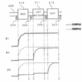
- the catalyst heat generation pattern represents a distribution shape of heat generation based on actual measurement in a route passing through the DOC 210, the NOx purification device 211, and the DPF 212 along the exhaust pipe 208.
- the temperature difference between the inlet and outlet of each catalyst is obtained based on the exhaust gas temperature at each catalyst inlet and outlet detected by the first to fourth temperature sensors 224 to 227, and from this temperature difference.
- the integrated heat generation amount in each catalyst can be calculated. This is the measured calorific value.
- the integrated heat generation amount that should be generated in each catalyst can be calculated by applying the exhaust pipe fuel injection amount, the heat generation coefficient of the fuel depending on each catalyst, the heat release amount, and the like to empirical formulas obtained in advance by experiments. This is the theoretical calorific value.
- the actually measured calorific value and the theoretical calorific value are obtained as follows, for example.
- the exhaust gas flow rate is calculated from each catalyst inlet temperature, intake air amount, and fuel injection amount during DPF regeneration.
- the instantaneous catalyst heating value is calculated from the temperature difference between the inlet and outlet of the DOC 210, the exhaust gas flow rate, and the exhaust gas specific heat.
- the integrated heat generation amount is calculated by integrating the catalyst heat generation amount.
- Instantaneous catalyst heating value DOC inlet / outlet temperature difference ⁇ exhaust gas flow rate ⁇ exhaust gas specific heat, the instantaneous catalyst heating value is calculated.
- the instantaneous theoretical calorific value is calculated from the lower calorific value (for example, 38.2 MJ / L) of the light oil as the fuel and the fuel consumption amount, and this is also integrated.
- Instantaneous calorific value Lower heating value of diesel oil x Fuel consumption
- the theoretical calorific value rises greatly in the vicinity of the inlet in the DOC 210 as shown by the broken line in the figure, and becomes constant thereafter.
- the catalyst heat generation pattern # 1 indicated by the solid line almost coincides with the distribution based on the theoretical heat generation amount.
- the catalyst heat generation pattern # 2 hardly rises in the DOC 210, rises greatly in the vicinity of the inlet in the NOx purification device 211, and becomes constant thereafter.
- the catalyst heat generation pattern # 3 hardly rises in the DOC 210 or the NOx purification device 211, and rises greatly in the vicinity of the inlet of the DPF 212.
- the measured heat generation amount and the theoretical heat generation amount in DOC 210 are in good agreement, and it can be determined that DOC 210 is functioning normally. Since the exhaust gas temperature has increased in the DOC 210, it cannot be determined from the catalyst heat generation pattern # 1 alone whether the NOx purification device 211 is functioning normally.
- the actual heat generation amount and the theoretical heat generation amount are greatly different in the DOC 210, the actual heat generation amount is large in the NOx purification device 211, and the heat generation amount distribution after the NOx purification device 211 matches. ing. From this, it can be determined that the DOC 210 is abnormal. Further, it can be determined that the temperature raising function of the NOx purification device 211 is normal.
- the measured heat generation amount and the theoretical heat generation amount are greatly different in the DOC 210 and the NOx purification device 211. Therefore, it can be determined that both the DOC 210 and the NOx purification device 211 are abnormal.
- the failure site can be identified.
- the error between the actual heat generation amount in the DOC 210 and the theoretical heat generation amount is within the threshold value. Can be determined to be normal. Since it has already been determined that there is no abnormality on the engine side and the exhaust pipe fuel injector 209 is also normal, only the NOx purification device 211 remains as a factor for reducing the NOx purification rate. Therefore, the NOx purification device failure identifying unit 5 identifies the cause of the decrease in the NOx purification rate as the NOx purification device failure.
- the threshold value is set with the theoretical calorific value ⁇ 0.8 as a guide.
- the catalyst heat generation pattern # 2 When the catalyst heat generation pattern # 2 is obtained, it is determined that the DOC 210 is abnormal. On the other hand, the error between the measured calorific value and the theoretical calorific value in the NOx purifying device 211 is within a threshold value (theoretical calorific value x 0.8 as a guideline), and although the temperature raising function of the NOx purifying device 211 is normal, the NOx purifying is performed. It cannot be uniquely determined that the cause of the rate decrease is an oxidation catalyst device failure. This is because, in the NOx purification device 211, the temperature raising function is normal, but the possibility that the NOx purification function is abnormal remains.
- a threshold value theoretical calorific value x 0.8 as a guideline
- the oxidation catalyst device failure identification unit 6 identifies the cause of the decrease in the NOx purification rate as an oxidation catalyst device failure.
- the combined failure identification unit 7 identifies the cause of the decrease in the NOx purification rate as the oxidation catalyst device failure and the NOx purification device failure.
- the diagnosis matrix of FIG. 5 can be defined equivalently to the control procedure of FIG. That is, as shown in FIG. 5, if the determination of ⁇ diagnosis A in step S2 is NG (abnormal), the cause of the decrease in the NOx purification rate is specified as an engine-side failure. If the determination of ⁇ diagnosis A in step S2 is OK (normal) and the determination of ⁇ diagnosis B in step S4 is NG, the cause of the decrease in the NOx purification rate is identified as an exhaust pipe fuel injector failure.
- the catalyst temperature diagnosis in step S5 is not executed. However, if it is executed, for example, a catalyst heat generation pattern in which there is no temperature rise is obtained for all catalysts, and the determination in this case is NG.
- both ⁇ diagnosis A and ⁇ diagnosis B are determined to be OK, it is as follows. If the determination of the catalyst temperature diagnosis is OK (the actual calorific value and the theoretical calorific value coincide, that is, the catalyst heat generation pattern # 1), it is specified that the NOx purification device has failed. If the determination of the catalyst temperature diagnosis is NG based on the catalyst heat generation pattern # 2, it is specified that the oxidation catalyst device has failed. If the determination of the catalyst temperature diagnosis is NG based on the catalyst heat generation pattern # 3, the oxidation catalyst device failure and the NOx purification device failure are identified.
- exhaust pipe fuel injection is performed for diagnosis when the NOx purification rate is decreased, and the catalyst temperature diagnosis of the DOC 210 is performed.
- a normal calorific value is obtained in the DOC 210, it can be identified as a NOx purification device failure, and if a normal calorific value is not obtained in the DOC 210, it can be identified as an oxidation catalyst device failure.
- ⁇ diagnosis A and ⁇ diagnosis B are performed as in this embodiment, engine-side failures and exhaust pipe fuel injector failures can be specified, and the failure classification can be further subdivided.
- the NOx purification rate lowering cause diagnosis apparatus 1 can be realized only by changing the software of the ECU without adding a new member to the engine system 201, so that the member cost does not increase.
- the present invention is applied to the engine system 201 in which the exhaust pipe fuel injector 209, the DOC 210, the NOx purification device 211, and the DPF 212 are installed in order from the upstream side of the exhaust pipe 208, but there is no DOC 210.
- the present invention can also be applied to an engine system in which the exhaust pipe fuel injector 209, the NOx purification device 211, and the DPF 212 are installed. Further, when the engine side failure, the exhaust pipe fuel injector failure, and the DPF failure are specified at the time of PM purification failure in the engine system in which the DOC 210 and the NOx purification device 211 are not provided and the exhaust pipe fuel injector 209 and the DPF 212 are installed.
- the present invention can be applied.
- the present invention can be applied to cause determination other than the urea water injector failure when the NOx purification rate is reduced.
Landscapes
- Engineering & Computer Science (AREA)
- Chemical & Material Sciences (AREA)
- Combustion & Propulsion (AREA)
- Chemical Kinetics & Catalysis (AREA)
- Mechanical Engineering (AREA)
- General Engineering & Computer Science (AREA)
- Health & Medical Sciences (AREA)
- Environmental & Geological Engineering (AREA)
- Biomedical Technology (AREA)
- Analytical Chemistry (AREA)
- General Chemical & Material Sciences (AREA)
- Oil, Petroleum & Natural Gas (AREA)
- Materials Engineering (AREA)
- Toxicology (AREA)
- Exhaust Gas After Treatment (AREA)
- Exhaust Gas Treatment By Means Of Catalyst (AREA)
Abstract
Description
NOx浄化率=(1-触媒後NOx濃度/エンジン出口NOx濃度)
×100 (%)
により演算される。エンジン出口NOx濃度は、第一NOxセンサ221を使用せずに、エンジンパラメータを用いた公知の理論式あるいはマップから推定してもよい。
瞬時の触媒発熱量=DOC出入口温度差×排気ガス流量×排気ガス比熱
により瞬時の触媒発熱量が演算される。一方、瞬時の理論発熱量は、燃料である軽油の低位発熱量(例えば、38.2MJ/L)と燃料消費量とから演算され、こちらも積算される。
瞬時の理論発熱量=軽油の低位発熱量×燃料消費量
2 診断用排気管燃料噴射制御部
3 エンジン側故障特定部
4 排気管燃料噴射器故障特定部
5 NOx浄化装置故障特定部
6 酸化触媒装置故障特定部
7 複合故障特定部
Claims (2)
- 排気管燃料噴射器と酸化触媒装置とNOx浄化装置とを有するエンジンシステムに適用されるNOx浄化率低下原因診断装置であって、
NOx浄化率の低下時に診断用に排気管燃料噴射を実施させる診断用排気管燃料噴射制御部と、
前記排気管燃料噴射実施時に前記酸化触媒装置での実測発熱量と理論発熱量との誤差が閾値以内であれば、NOx浄化率低下の原因はNOx浄化装置故障と特定するNOx浄化装置故障特定部と、
前記排気管燃料噴射実施時に前記酸化触媒装置での実測発熱量と理論発熱量との誤差が閾値を超えていれば、NOx浄化率低下の原因は酸化触媒装置と特定する酸化触媒装置故障特定部とを備えたことを特徴とするNOx浄化率低下原因診断装置。 - 排気管燃料噴射実施時に前記酸化触媒装置での実測発熱量と理論発熱量との誤差が閾値を超えており、かつ、前記NOx浄化装置での実測発熱量と理論発熱量との誤差が閾値を超えていれば、酸化触媒装置故障及びNOx浄化装置故障と特定する複合故障特定部をさらに備えた
請求項1記載のNOx浄化率低下原因診断装置。
Priority Applications (4)
| Application Number | Priority Date | Filing Date | Title |
|---|---|---|---|
| EP11848567.1A EP2653684B1 (en) | 2010-12-16 | 2011-12-07 | DEVICE FOR DIAGNOSING CAUSES OF DECREASES IN NOx CONVERSION EFFICIENCY |
| US13/994,493 US8973431B2 (en) | 2010-12-16 | 2011-12-07 | Apparatus for diagnosing causes of NOx conversion efficiency degradation |
| AU2011342305A AU2011342305B2 (en) | 2010-12-16 | 2011-12-07 | Device for diagnosing causes of decreases in NOx conversion efficiency |
| CN201180059961.4A CN103261609B (zh) | 2010-12-16 | 2011-12-07 | NOx净化率降低原因诊断装置 |
Applications Claiming Priority (2)
| Application Number | Priority Date | Filing Date | Title |
|---|---|---|---|
| JP2010-280889 | 2010-12-16 | ||
| JP2010280889A JP5760423B2 (ja) | 2010-12-16 | 2010-12-16 | NOx浄化率低下原因診断装置 |
Publications (1)
| Publication Number | Publication Date |
|---|---|
| WO2012081464A1 true WO2012081464A1 (ja) | 2012-06-21 |
Family
ID=46244571
Family Applications (1)
| Application Number | Title | Priority Date | Filing Date |
|---|---|---|---|
| PCT/JP2011/078284 Ceased WO2012081464A1 (ja) | 2010-12-16 | 2011-12-07 | NOx浄化率低下原因診断装置 |
Country Status (6)
| Country | Link |
|---|---|
| US (1) | US8973431B2 (ja) |
| EP (1) | EP2653684B1 (ja) |
| JP (1) | JP5760423B2 (ja) |
| CN (1) | CN103261609B (ja) |
| AU (1) | AU2011342305B2 (ja) |
| WO (1) | WO2012081464A1 (ja) |
Families Citing this family (20)
| Publication number | Priority date | Publication date | Assignee | Title |
|---|---|---|---|---|
| KR101158816B1 (ko) * | 2009-08-21 | 2012-06-26 | 기아자동차주식회사 | 디젤 차량의 배기 장치 |
| JP5360307B2 (ja) * | 2010-11-02 | 2013-12-04 | トヨタ自動車株式会社 | 内燃機関の制御装置 |
| EP2682576A4 (en) * | 2011-03-03 | 2015-04-08 | Toyota Motor Co Ltd | SYSTEM FOR DETERMINING CATALYST WEAR |
| AT512760B1 (de) * | 2012-03-21 | 2014-05-15 | Avl List Gmbh | Verfahren zum Betreiben einer Brennkraftmaschine |
| US9084966B2 (en) * | 2012-11-29 | 2015-07-21 | GM Global Technology Operations LLC | Diesel oxidation catalyst aging level determination using NOX sensor NO2 interference |
| US9708960B2 (en) * | 2013-05-08 | 2017-07-18 | Cummins Ip, Inc. | Exhaust aftertreatment system diagnostic and conditioning |
| JP6169427B2 (ja) * | 2013-07-10 | 2017-07-26 | 日野自動車株式会社 | アフターターボキャタリストの異常検知方法 |
| US9068495B2 (en) * | 2013-09-12 | 2015-06-30 | GM Global Technology Operations LLC | Oxidation catalyst/hydrocarbon injector testing system |
| US9752488B2 (en) * | 2015-10-27 | 2017-09-05 | Cummins, Inc. | Systems and methods of an on-board NOx monitor reset test |
| US10208696B2 (en) * | 2016-10-21 | 2019-02-19 | GM Global Technology Operations LLC | Multivariable engine torque and emission closed-loop control for internal combustion engine |
| DE102017124757A1 (de) * | 2017-10-23 | 2017-12-28 | FEV Europe GmbH | Abgasbehandlungssystem für ein kraftfahrzeug |
| DE112017008280T5 (de) * | 2017-12-18 | 2020-09-10 | Cummins Emission Solutions Inc. | Dezidierte Wärmeverwaltung für ein SCR-System |
| CN108930578B (zh) * | 2018-06-27 | 2020-09-29 | 潍柴动力股份有限公司 | Doc中毒的检测和保护方法 |
| JP7310720B2 (ja) * | 2020-05-29 | 2023-07-19 | いすゞ自動車株式会社 | 触媒状態検知装置 |
| CN112557040B (zh) * | 2020-11-16 | 2022-03-15 | 东风汽车集团有限公司 | 发动机瞬态soot排放量预估方法 |
| DE102021200701A1 (de) * | 2021-01-27 | 2022-07-28 | Robert Bosch Gesellschaft mit beschränkter Haftung | Verfahren und Vorrichtung zur Diagnose eines Katalysators mit einem elektrischen Heizer |
| GB2619856B (en) * | 2021-03-26 | 2025-03-26 | Cummins Power Generation Inc | Dual leg aftertreatment system |
| CN114991921B (zh) * | 2022-05-25 | 2024-01-09 | 深圳市众卡汽车零部件有限公司 | 一种scr效率低故障原因排查方法 |
| US11815044B1 (en) | 2022-06-09 | 2023-11-14 | Cummins Inc. | Systems and methods for selective catalytic reduction (SCR) multipoint diagnosis |
| KR20260048751A (ko) * | 2024-10-04 | 2026-04-13 | 현대자동차주식회사 | 오토 인코더를 이용한 배출 가스의 증가 원인 진단 장치, 방법 및 차량 |
Citations (6)
| Publication number | Priority date | Publication date | Assignee | Title |
|---|---|---|---|---|
| JP2005201143A (ja) * | 2004-01-15 | 2005-07-28 | Honda Motor Co Ltd | 排気浄化装置の劣化判定装置 |
| JP2005351153A (ja) * | 2004-06-10 | 2005-12-22 | Toyota Motor Corp | 触媒劣化判定装置 |
| JP2006291742A (ja) * | 2005-04-06 | 2006-10-26 | Toyota Motor Corp | 内燃機関の触媒劣化検出装置 |
| JP2008075610A (ja) | 2006-09-23 | 2008-04-03 | Hino Motors Ltd | 排気処理装置 |
| JP2009085079A (ja) * | 2007-09-28 | 2009-04-23 | Toyota Motor Corp | 内燃機関の触媒劣化検出装置 |
| JP2010196496A (ja) | 2009-02-23 | 2010-09-09 | Toyota Motor Corp | 排気浄化装置 |
Family Cites Families (10)
| Publication number | Priority date | Publication date | Assignee | Title |
|---|---|---|---|---|
| DE10237382A1 (de) * | 2002-08-12 | 2004-03-04 | Volkswagen Ag | Verfahren zum Betrieb eines magerlauffähigen Verbrennungsmotors mit einem Abgasreinigungssystem |
| US6925796B2 (en) * | 2003-11-19 | 2005-08-09 | Ford Global Technologies, Llc | Diagnosis of a urea SCR catalytic system |
| US20070044456A1 (en) * | 2005-09-01 | 2007-03-01 | Devesh Upadhyay | Exhaust gas aftertreatment systems |
| US7418816B2 (en) * | 2005-09-01 | 2008-09-02 | Ford Global Technologies, Llc | Exhaust gas aftertreatment systems |
| US8245567B2 (en) * | 2008-08-19 | 2012-08-21 | GM Global Technology Operations LLC | On board diagnostic monitor of NOx conversion efficiency for aftertreatment device |
| US8201444B2 (en) * | 2008-08-19 | 2012-06-19 | GM Global Technology Operations LLC | Aftertreatment device NOx conversion efficiency diagnostics using on board adaptive diagnostic algorithm |
| JP5170689B2 (ja) * | 2009-01-14 | 2013-03-27 | トヨタ自動車株式会社 | 内燃機関の排気浄化装置 |
| US8539757B2 (en) * | 2009-01-16 | 2013-09-24 | Toyota Jidosha Kabushiki Kaisha | Exhaust purification apparatus for internal combustion engine |
| US8091416B2 (en) * | 2009-01-16 | 2012-01-10 | GM Global Technology Operations LLC | Robust design of diagnostic enabling conditions for SCR NOx conversion efficiency monitor |
| US8726723B2 (en) * | 2010-02-23 | 2014-05-20 | Cummins Emission Solutions | Detection of aftertreatment catalyst degradation |
-
2010
- 2010-12-16 JP JP2010280889A patent/JP5760423B2/ja not_active Expired - Fee Related
-
2011
- 2011-12-07 US US13/994,493 patent/US8973431B2/en active Active
- 2011-12-07 WO PCT/JP2011/078284 patent/WO2012081464A1/ja not_active Ceased
- 2011-12-07 EP EP11848567.1A patent/EP2653684B1/en not_active Not-in-force
- 2011-12-07 CN CN201180059961.4A patent/CN103261609B/zh active Active
- 2011-12-07 AU AU2011342305A patent/AU2011342305B2/en not_active Ceased
Patent Citations (6)
| Publication number | Priority date | Publication date | Assignee | Title |
|---|---|---|---|---|
| JP2005201143A (ja) * | 2004-01-15 | 2005-07-28 | Honda Motor Co Ltd | 排気浄化装置の劣化判定装置 |
| JP2005351153A (ja) * | 2004-06-10 | 2005-12-22 | Toyota Motor Corp | 触媒劣化判定装置 |
| JP2006291742A (ja) * | 2005-04-06 | 2006-10-26 | Toyota Motor Corp | 内燃機関の触媒劣化検出装置 |
| JP2008075610A (ja) | 2006-09-23 | 2008-04-03 | Hino Motors Ltd | 排気処理装置 |
| JP2009085079A (ja) * | 2007-09-28 | 2009-04-23 | Toyota Motor Corp | 内燃機関の触媒劣化検出装置 |
| JP2010196496A (ja) | 2009-02-23 | 2010-09-09 | Toyota Motor Corp | 排気浄化装置 |
Also Published As
| Publication number | Publication date |
|---|---|
| US8973431B2 (en) | 2015-03-10 |
| JP5760423B2 (ja) | 2015-08-12 |
| EP2653684A4 (en) | 2016-11-09 |
| CN103261609A (zh) | 2013-08-21 |
| AU2011342305A1 (en) | 2013-07-18 |
| US20130306171A1 (en) | 2013-11-21 |
| AU2011342305B2 (en) | 2016-02-25 |
| EP2653684B1 (en) | 2018-05-30 |
| CN103261609B (zh) | 2015-04-29 |
| JP2012127302A (ja) | 2012-07-05 |
| EP2653684A1 (en) | 2013-10-23 |
Similar Documents
| Publication | Publication Date | Title |
|---|---|---|
| JP5760423B2 (ja) | NOx浄化率低下原因診断装置 | |
| JP5720230B2 (ja) | パティキュレートフィルタシステム | |
| CN105888797B (zh) | 用于监测颗粒过滤器的方法 | |
| JP6325532B2 (ja) | 異常に頻度が高いディーゼルパティキュレートフィルタ再生を検出する方法、エンジン、排気後処理システム、警告システム及び方法 | |
| JP5993293B2 (ja) | 異常診断装置 | |
| US9074507B2 (en) | Event-based deviation integration temperature control loop diagnostic system | |
| US20120023911A1 (en) | Detection of exhaust particulate filter substrate failure | |
| US20150240695A1 (en) | Detecting over-temperature in exhaust system | |
| US20140144220A1 (en) | Diagnostic operation strategy for diesel oxidation catalyst aging level determination using nox sensor no2 interference | |
| CN101379284A (zh) | 废气净化系统的控制方法及废气净化系统 | |
| CN102037230A (zh) | NOx传感器的异常诊断装置及异常诊断方法 | |
| CN101278110A (zh) | 用于排气后处理系统的诊断方法 | |
| JP2012036860A (ja) | 触媒劣化診断装置 | |
| KR20150024384A (ko) | 배기 후 처리 시스템의 구성요소 모니터링 방법, 배기 처리 시스템 및 배기 처리 시스템 컨트롤러 | |
| US20130025262A1 (en) | Exhaust purification apparatus for engine | |
| JP2010523891A (ja) | 内燃機関の排気管の触媒コンバータの作動状態を制御する方法及び装置 | |
| KR20190134944A (ko) | 배기 정화 시스템 및 이의 제어방법 | |
| JP2019116876A (ja) | センサ診断システム | |
| JP5831162B2 (ja) | NOxセンサの異常診断方法、NOxセンサの異常診断システム、及び内燃機関 | |
| WO2013073450A1 (ja) | NOxセンサの異常診断方法、NOxセンサの異常診断システム、及び内燃機関 | |
| JP6958130B2 (ja) | 内燃機関の診断装置 | |
| JP2021173218A (ja) | 触媒劣化度推定装置 | |
| JP2016188626A (ja) | ドージングバルブの交換時期診断方法 | |
| JP5874342B2 (ja) | NOxセンサの異常診断方法、NOxセンサの異常診断システム、及び内燃機関のNOx排出濃度推定方法 | |
| JP2022018447A (ja) | 温度センサの診断装置 |
Legal Events
| Date | Code | Title | Description |
|---|---|---|---|
| 121 | Ep: the epo has been informed by wipo that ep was designated in this application |
Ref document number: 11848567 Country of ref document: EP Kind code of ref document: A1 |
|
| WWE | Wipo information: entry into national phase |
Ref document number: 13994493 Country of ref document: US |
|
| NENP | Non-entry into the national phase |
Ref country code: DE |
|
| WWE | Wipo information: entry into national phase |
Ref document number: 2011848567 Country of ref document: EP |
|
| ENP | Entry into the national phase |
Ref document number: 2011342305 Country of ref document: AU Date of ref document: 20111207 Kind code of ref document: A |