WO2012081612A1 - 移動局装置、基地局装置、無線通信システム、制御方法及び集積回路 - Google Patents
移動局装置、基地局装置、無線通信システム、制御方法及び集積回路 Download PDFInfo
- Publication number
- WO2012081612A1 WO2012081612A1 PCT/JP2011/078892 JP2011078892W WO2012081612A1 WO 2012081612 A1 WO2012081612 A1 WO 2012081612A1 JP 2011078892 W JP2011078892 W JP 2011078892W WO 2012081612 A1 WO2012081612 A1 WO 2012081612A1
- Authority
- WO
- WIPO (PCT)
- Prior art keywords
- transmission timing
- station apparatus
- cells
- group
- mobile station
- Prior art date
- Legal status (The legal status is an assumption and is not a legal conclusion. Google has not performed a legal analysis and makes no representation as to the accuracy of the status listed.)
- Ceased
Links
Images




Classifications
-
- H—ELECTRICITY
- H04—ELECTRIC COMMUNICATION TECHNIQUE
- H04W—WIRELESS COMMUNICATION NETWORKS
- H04W72/00—Local resource management
- H04W72/20—Control channels or signalling for resource management
- H04W72/21—Control channels or signalling for resource management in the uplink direction of a wireless link, i.e. towards the network
-
- H—ELECTRICITY
- H04—ELECTRIC COMMUNICATION TECHNIQUE
- H04W—WIRELESS COMMUNICATION NETWORKS
- H04W56/00—Synchronisation arrangements
- H04W56/0005—Synchronisation arrangements synchronizing of arrival of multiple uplinks
-
- H—ELECTRICITY
- H04—ELECTRIC COMMUNICATION TECHNIQUE
- H04W—WIRELESS COMMUNICATION NETWORKS
- H04W72/00—Local resource management
- H04W72/04—Wireless resource allocation
- H04W72/044—Wireless resource allocation based on the type of the allocated resource
- H04W72/0446—Resources in time domain, e.g. slots or frames
-
- H—ELECTRICITY
- H04—ELECTRIC COMMUNICATION TECHNIQUE
- H04W—WIRELESS COMMUNICATION NETWORKS
- H04W74/00—Wireless channel access
- H04W74/08—Non-scheduled access, e.g. ALOHA
- H04W74/0833—Random access procedures, e.g. with 4-step access
-
- H—ELECTRICITY
- H04—ELECTRIC COMMUNICATION TECHNIQUE
- H04W—WIRELESS COMMUNICATION NETWORKS
- H04W74/00—Wireless channel access
- H04W74/08—Non-scheduled access, e.g. ALOHA
- H04W74/0833—Random access procedures, e.g. with 4-step access
- H04W74/0838—Random access procedures, e.g. with 4-step access using contention-free random access [CFRA]
Definitions
- the present invention relates to a base station device, a mobile station device, and a radio communication system, and more specifically, a mobile station device, a base station device, a radio communication system, and an operation when an uplink transmission timing becomes invalid,
- the present invention relates to a control method and an integrated circuit.
- the W-CDMA system has been standardized as a third generation cellular mobile communication system, and services have been started sequentially.
- HSDPA with higher communication speed has also been standardized and the service has started.
- EUTRA Evolved Universal Terrestrial Radio Access
- OFDM Orthogonal Frequency Division Multiplexing
- SC-FDMA Peak to Average Power Ratio
- DFT Single Carrier-Frequency Division Multiple Access
- Discrete Fourier Transform spread Fourier transform
- Advanced-EUTRA a further evolution of EUTRA.
- communication at a maximum transmission rate of 1 Gbps or higher and 500 Mbps or higher of the uplink is performed using a band up to a maximum of 100 MHz bandwidth in the uplink and the downlink, respectively.
- Advanced-EUTRA is considering to realize a maximum of 100 MHz band by bundling a plurality of bands below 20 MHz of EUTRA so that EUTRA mobile station devices can be accommodated.
- one band of 20 MHz or less of EUTRA is referred to as “Component Carrier (CC)” (non-patent document 2 described later).
- CC Component Carrier
- one cell is configured by combining one downlink component carrier and one uplink component carrier.
- a single cell can be configured with only one downlink component carrier.
- the base station apparatus allocates a plurality of cells to the mobile station apparatus and communicates with the mobile station apparatus via the allocated cells.
- 3GPP TS Technical Specification 36.300, V9.40 (2010-06), Evolved Universal Terrestrial Radio Access (E-UTRA) and Evolved Universal Terrestrial Radio Access Network (E-UTRAN), Overall description Stage2 3GPP TR (Technical Specification) 36.814, V9.00 (2010-03), Evolved Universal Terrestrial Radio Access (E-UTRA) Further advancements for E-UTRA physical layer aspects
- the mobile station apparatus When the mobile station apparatus communicates with the base station apparatus using a plurality of cells, the mobile station apparatus may connect to the base station apparatus via a repeater (Repeator) or the like. In such a case, the reception timing of data from the downlink component carrier in the mobile station apparatus differs for each cell. Furthermore, the transmission timing to the base station apparatus is different for each uplink component carrier of each cell. Therefore, the mobile station apparatus needs to perform transmission of data to the base station apparatus by adjusting the transmission timing for each uplink component carrier of each cell or for each group of component carriers having the same transmission timing.
- a repeater peerator
- the mobile station apparatus since it is necessary to adjust the transmission timing for each uplink component carrier of each cell or for each group of component carriers having the same transmission timing, transmits each uplink component carrier of each cell or transmits It is necessary to have a transmission timing timer indicating the effective period of transmission timing for each group of component carriers having the same timing.
- the mobile station apparatus adjusts the transmission timing for each uplink component carrier of each cell, the transmission timing is updated for each cell or the transmission timing becomes invalid. Therefore, it is necessary to consider the efficient operation of the mobile station apparatus when the transmission timing is updated or when the transmission timing becomes invalid.
- An object of the present invention is to provide a mobile station device, a base station device, a wireless communication system, a control method, and an integrated circuit.
- the mobile station apparatus of the present invention is a mobile station apparatus in which a base station apparatus allocates a plurality of cells and communicates with the base station apparatus via the plurality of cells, and the plurality of cells includes one first cell.
- the uplink transmission timing is managed using a transmission timing timer, and when the transmission timing timer of the first group expires, all uplink transmissions to the plurality of cells are stopped, and the transmission of the second group If the timing timer expires, uplink transmission for the second group of cells whose transmission timing timer has expired Characterized in that it stop.
- the mobile station apparatus of the present invention deletes data in all transmission HARQ buffers corresponding to the plurality of cells, and the second group When the transmission timing timer expires, data in the transmission HARQ buffer corresponding to the second group of cells for which the transmission timing timer has expired is erased.
- the mobile station apparatus of the present invention releases radio resources of the measurement reference signals allocated to the plurality of cells, and
- the transmission timing timer of the second group expires, the radio resource of the reference signal for measurement assigned to the cell of the second group whose transmission timing timer has expired is released.
- the mobile station apparatus of the present invention discards all the uplink shared channel and downlink shared channel allocation information, and When the transmission timing timer expires, the uplink shared channel allocation information allocated to the cell of the second group whose transmission timing timer has expired is discarded.
- the base station apparatus of the present invention is a base station apparatus in which a plurality of cells are allocated to a mobile station apparatus and communicates with the mobile station apparatus via the cell. Grouped into a first group consisting of cells with the same uplink transmission timing as one cell and a second group consisting of one or more cells with uplink transmission timing different from the first cell, The uplink transmission timing is managed using a transmission timing timer for each group, and when the transmission timing timer of the group including the first cell expires, the allocation process of the uplink shared channel to the plurality of cells is stopped. If the transmission timing timer of the second group expires, the second group of which the transmission timing timer has expired. Characterized by stopping the process of allocating uplink shared channel for the cell-loop.
- the base station apparatus of this invention erase
- the transmission timing timer of the second group expires, the received HARQ buffer data corresponding to the cell of the second group is erased.
- the base station apparatus of the present invention releases the radio resources of the measurement reference signals allocated to the plurality of cells of the mobile station apparatus,
- the transmission timing timer of the second group expires, the radio resource of the reference signal for measurement allocated to the cell of the second group of the mobile station device is released.
- the radio communication system of the present invention is a radio communication system in which a base station apparatus allocates a plurality of cells and communicates with the base station apparatus via the cells. Grouped into a first group composed of cells having the same uplink transmission timing as the cell and a second group composed of one or more cells having uplink transmission timing different from the first cell, The uplink transmission timing is managed using a transmission timing timer every time, and when the transmission timing timer of the first group expires, the base station apparatus can share the uplink for the plurality of cells of the mobile station apparatus.
- the mobile station apparatus stops all uplink transmission for the plurality of cells.
- the base station apparatus stops the uplink shared channel allocation process for the cells of the second group for which the transmission timing timer of the mobile station apparatus has expired, and the mobile station apparatus The station apparatus stops uplink transmission for the second group of cells for which the transmission timing timer has expired.
- control method of the present invention is a control method of a mobile station apparatus in which a base station apparatus allocates a plurality of cells and communicates with the base station apparatus through the cells. Grouped into a first group composed of cells of the same uplink transmission timing as the first cell and a second group composed of cells of uplink transmission timing different from the one or more first cells, The uplink transmission timing is managed using a transmission timing timer for each group, and when the transmission timing timer of the first group expires, stopping all uplink transmissions for the plurality of cells; When the transmission timing timer of the second group expires, the second group of cells whose transmission timing timer has expired Characterized in that it comprises a step of stopping the uplink transmission that.
- the control method of the present invention is a control method of a base station apparatus in which a mobile station apparatus is assigned a plurality of cells and communicates with the mobile station apparatus via the cells, and the plurality of cells is 1 Grouped into a first group composed of cells having the same uplink transmission timing as one first cell and a second group composed of cells having uplink transmission timing different from one or more of the first cells.
- the uplink transmission timing is managed using a transmission timing timer for each group, and when the transmission timing timer of the first group expires, allocation of an uplink shared channel to the plurality of cells of the mobile station device.
- An integrated circuit according to the present invention is an integrated circuit applied to a mobile station apparatus in which a base station apparatus allocates a plurality of cells and communicates with the base station apparatus through the cells. Are grouped into a first group composed of cells having the same uplink transmission timing as one first cell and a second group composed of cells having uplink transmission timings different from one or more of the first cells.
- the uplink transmission timing is managed using a transmission timing timer for each group, and when the transmission timing timer of the first group expires, all uplink transmissions for the plurality of cells are stopped. And when the transmission timing timer of the second group expires, the group of the group for which the transmission timing timer has expired. Characterized in that it comprises means for stopping the uplink transmission to.
- An integrated circuit according to the present invention is an integrated circuit applied to a base station apparatus to which a mobile station apparatus is assigned a plurality of cells and communicates with the mobile station apparatus via the cells.
- the cell is composed of a first group composed of cells having the same uplink transmission timing as one first cell and a second group composed of cells having uplink transmission timings different from one or more of the first cells.
- the uplink transmission timing is managed using a transmission timing timer for each group, and when the transmission timing timer of the first group expires, uplink sharing for the plurality of cells of the mobile station apparatus is performed Means for stopping channel assignment processing and when the transmission timing timer of the second group expires, the mobile station apparatus Characterized in that it comprises means for stopping the allocation processing of the uplink shared channel for a second group of cells the transmission timing timer has expired.
- the uplink transmission timing is different in each cell, and the transmission timing timer expires for each transmission timing cell group, the transmission timing timer has expired.
- the mobile station apparatus stops the transmission process of each cell and does not perform a useless transmission process operation. Thereby, efficient transmission control of the mobile station apparatus can be realized.
- the downlink of EUTRA includes downlink reference signal (Downlink Pilot Signal), downlink synchronization channel DSCH (Downlink Synchronization Channel), downlink shared channel PDSCH (Physical Downlink Shared Channel), downlink control channel PDCCH (Physical Downlink Control Channel).
- the broadcast channel PBCH Physical Broadcast Physical Channel.
- the uplink of EUTRA is based on the uplink reference signal (Uplink Pilot Signal), random access channel RACH (Random Access Channel), uplink shared channel PUSCH (Physical Uplink Shared Channel), uplink control channel PUCCH (Physical Uplink Control Channel). It is configured.
- the uplink reference signal includes two types of signals: a demodulation reference signal (Demodulation Reference Signal) and a measurement reference signal (Sounding Reference Signal).
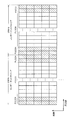
- FIG. 6 is a diagram showing a channel configuration in EUTRA.
- FIG. 7 is a diagram illustrating an uplink configuration in EUTRA.
- One block includes 12 subcarriers and 7 OFDM symbols.
- One resource block (RB) is configured using two blocks.
- the uplink shared channel PUSCH and the uplink control channel PUCCH are used in units of one resource block.
- the random access channel RACH is configured using 6 resource blocks.
- the uplink reference signal is arranged in a specific OFDM symbol in the resource block.
- each uplink channel is divided into an uplink shared channel PUSCH region, an uplink control channel PUCCH region, and a random access channel RACH.
- Information on each region of the uplink shared channel PUSCH and the uplink control channel PUCCH is broadcast from the base station apparatus.
- the base station apparatus allocates radio resources for the uplink shared channel PUSCH and the uplink control channel PUCCH for each mobile station apparatus from each region.
- the random access channel RACH is arranged at a constant period.
- the downlink shared channel PDSCH is used for transmitting user data and control data from the base station apparatus to the mobile station apparatus.
- the downlink control channel PDCCH is used for notification of control information such as radio resource allocation information for the downlink shared channel PDSCH and the uplink shared channel PUSCH from the base station apparatus to the mobile station apparatus.
- the downlink reference signal is used to demodulate the downlink shared channel PDSCH and the downlink control channel PDCCH.
- the downlink synchronization channel DSCH is used for the mobile station apparatus to perform downlink synchronization.
- the broadcast channel PBCH is used to notify information related to system information of the base station apparatus.
- the uplink shared channel PUSCH is used for transmitting user data and control data from the mobile station apparatus to the base station apparatus.
- the data transmitted / received by the uplink shared channel PUSCH and the downlink shared channel PDSCH is subjected to HARQ (Hybrid Automatic Repeat reQuset) processing, and by combining the initial transmission data and the retransmission data at the time of retransmission, Improves data error correction capability.
- the uplink control channel PUCCH is used for notifying control information such as a response (Ack (Acknowledge) / Nack (Negative acknowledge)) to downlink data from the base station apparatus and downlink radio channel quality information.
- the random access channel RACH is mainly used for random access preamble transmission for acquiring transmission timing information from the mobile station apparatus to the base station apparatus. Random access preamble transmission is performed in a random access procedure.
- the reference signal for demodulation of the uplink reference signal is used by the base station apparatus to demodulate the uplink shared channel PUSCH.
- the demodulation reference signal is inserted into the fourth symbol position and the eleventh symbol position of the uplink shared channel PUSCH.
- the reference signal for measuring the uplink reference signal is used by the base station apparatus to measure the uplink radio channel quality.
- the measurement reference signal is inserted into the 14th symbol position of the uplink shared channel PUSCH.
- the radio resource for transmitting the measurement reference signal is allocated from the base station device to each mobile station device.
- Non-contention based Random Access Non-contention based random access
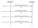
- FIG. 8 is a diagram showing the procedure of Contention based Random Access.
- Contention based Random Access is a random access that may collide between mobile station devices.
- Contention based Random Access (i) during initial access from a state where it is not connected (communication) with the base station device, (ii) is connected to the base station device, but moves in a state where uplink synchronization is lost This is performed for a scheduling request or the like when uplink data transmission occurs in the station apparatus.
- Non-contention based Random Access is a random access in which no collision occurs between mobile station devices.
- the base station device and the mobile station device are connected, but (i) uplink synchronization between the mobile station device and the base station device is quickly performed when uplink synchronization is lost.
- Non-contention based Random Access is instructed from the base station device in special cases such as when the transmission timing of the mobile station device is not valid.
- the mobile station apparatus starts random access (Non-patent Document 1).
- Non-contention based Random Access is indicated by RRC (Radio Resource Control: Layer 3) layer message and downlink control channel PDCCH control data.
- the mobile station apparatus 1-1 transmits a random access preamble to the base station apparatus 3 (message 1: (1), step S1).
- the base station device 3 that has received the random access preamble transmits a response to the random access preamble (random access response) to the mobile station device 1-1 (message 2: (2), step S2).
- the mobile station device 1-1 transmits an upper layer (Layer2 / Layer3) message based on the scheduling information included in the random access response (message 3: (3), step S3).
- the base station device 3 transmits a collision confirmation message to the mobile station device 1-1 that has received the upper layer message of (3) (message 4: (4), step S4).
- Contention based Random Access is also referred to as “random preamble transmission”.
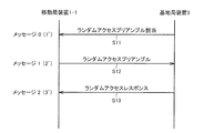
- the base station apparatus 3 notifies the mobile station apparatus 1-1 of the preamble number (or sequence number) and the random access channel number to be used (message 0: (1) ′, step S11).
- the mobile station apparatus 1-1 transmits the random access preamble having the designated preamble number to the designated random access channel RACH (message 1: (2) ', step S12).
- the base station device 3 that has received the random access preamble transmits a response to the random access preamble (random access response) to the mobile station device 1-1 (message 2: (3) ', step S13).
- the mobile station apparatus 1-1 performs Contention based Random Access.
- Non-contention based Random Access is also referred to as “dedicated preamble transmission”.
- the mobile station apparatus 1-1 acquires the system information of the base station apparatus 3 from the broadcast channel PBCH or the like.
- the mobile station apparatus 1-1 executes a random access procedure from the random access related information included in the system information and connects to the base station apparatus 3.
- the mobile station apparatus 1-1 generates a random access preamble from the random access related information in the system information.
- the mobile station apparatus 1-1 transmits a random access preamble using the random access channel RACH (message 1: (1)).
- the base station apparatus 3 When the base station apparatus 3 detects (i) a random access preamble from the mobile station apparatus 1-1, the base station apparatus 3 calculates an amount of transmission timing shift between the mobile station apparatus 1-1 and the base station apparatus 3 from the random access preamble. And (ii) scheduling (designation of uplink radio resource position (position of uplink shared channel PUSCH), transmission format (message size), etc.) for transmitting the Layer 2 (L2) / Layer 3 (L3) message, ( iii) Temporary C-RNTI (Cell-Radio Network Temporary Identity: mobile station device identification information) is allocated, and (iv) Random access channel RACH random access preamble is transmitted to downlink control channel PDCCH.
- Random accessless RA-RNTI Random Access-Radio Network Temporary Identity: random access response identification information
- transmission timing information scheduling information
- Temporary C-RNTI received random
- a random access response message including access preamble information is transmitted (message 2: (2)).
- the mobile station apparatus 1-1 When the mobile station apparatus 1-1 detects that the RA-RNTI is present in the downlink control channel PDCCH, the mobile station apparatus 1-1 confirms the content of the random access response message arranged in the downlink shared channel PDSCH. When the transmitted random access preamble information is included, the mobile station apparatus 1-1 adjusts the uplink transmission timing from the transmission timing information, and uses C-RNTI (or Temporary) with the scheduled radio resource and transmission format. An L2 / L3 message including information for identifying the mobile station device 1-1 such as C-RNTI) or IMSI (International Mobile Subscriber Identity) is transmitted (message 3: (3)). When the transmission timing is adjusted, the mobile station apparatus 1-1 starts a transmission timing timer in which the adjusted transmission timing is valid.
- C-RNTI or Temporary
- the adjusted transmission timing becomes invalid. While the transmission timing is valid, the mobile station apparatus 1-1 can transmit data to the base station apparatus. When the transmission timing is invalid, the mobile station apparatus 1-1 can only transmit a random access preamble. Further, a period in which the transmission timing is valid is referred to as an “uplink synchronization state”, and a period in which the transmission timing is not valid is also referred to as an “uplink asynchronous state”.
- the base station apparatus 3 When the base station apparatus 3 receives the L2 / L3 message from the mobile station apparatus 1-1, the base station apparatus 3 uses the C-RNTI (or Temporary C-RNTI) or IMSI included in the received L2 / L3 message.
- C-RNTI or Temporary C-RNTI
- IMSI included in the received L2 / L3 message.
- a collision confirmation (contention resolution) message for determining whether or not a collision occurs between 1-1 and 1-3 is transmitted to the mobile station apparatus 1-1 (message 4: (4)).
- the mobile station apparatus 1-1 does not detect the random access response message including the preamble number corresponding to the random access preamble transmitted within the predetermined period, fails to transmit the message 3, or is fixed period. If the identification information of the mobile station device 1-1 is not detected in the collision confirmation message, transmission is repeated from transmission of the random access preamble (message 1: (1)). When the number of random access preamble transmissions exceeds the maximum number of random access preamble transmissions indicated by the system information, the mobile station device 1-1 determines that the random access has failed and performs communication with the base station device 3. Disconnect. After the random access procedure is successful, control data for connection is further exchanged between the base station apparatus 3 and the mobile station apparatus 1-1. At this time, the base station apparatus 3 notifies the mobile station apparatus 1-1 of the uplink reference signal and the uplink control channel PUCCH allocation information that are individually allocated.
- the update of the uplink transmission timing after completion of the random access procedure is performed by the base station device 3 (i) an uplink reference signal (measurement reference signal) transmitted from the mobile station device 1-1.
- the transmission timing information is calculated by measuring (demodulation reference signal), and (ii) the calculated transmission timing information is notified to the mobile station apparatus 1-1.
- the mobile station apparatus 1-1 updates the transmission timing information notified from the base station apparatus 3, the mobile station apparatus 1-1 restarts the transmission timing timer.
- the base station apparatus 3 also holds the same transmission timing timer as that of the mobile station apparatus 1-1, and the base station apparatus 3 starts or restarts the transmission timing timer when transmitting the transmission timing information. In this way, the uplink synchronization state is managed in the base station device 3 and the mobile station device 1-1.
- the transmission timing timer expires, the transmission timing becomes invalid, and uplink transmission other than the random access preamble transmission is stopped.
- Advanced-EUTRA a further evolution of EUTRA.
- communication at a maximum transmission rate of 1 Gbps or higher and 500 Mbps or higher of the uplink is performed using a band up to a maximum of 100 MHz bandwidth in the uplink and the downlink, respectively.
- FIG. 11 is an explanatory diagram of a downlink component carrier in Advanced-EUTRA.
- FIG. 12 is an explanatory diagram of an uplink component carrier in Advanced-EUTRA.
- Advanced-EUTRA is considering to realize a maximum of 100 MHz band by bundling a plurality of bands below 20 MHz of EUTRA so that EUTRA mobile station devices can be accommodated.
- one band of 20 MHz or less of EUTRA is called a “Component Carrier (CC)” (Non-patent Document 2).
- CC Component Carrier
- one cell is configured by combining one downlink component carrier and one uplink component carrier.
- a single cell can be configured with only one downlink component carrier.
- Advanced-EUTRA communication is performed using a plurality of cells. Therefore, in order to reduce the load on the base station apparatus and the mobile station apparatus as much as possible, one cell among the plurality of cells is designated as a first cell (Primary Cell). ) And other cells are designated as secondary cells. And the special function is set to the 1st cell, such as allocation of the uplink control channel PUCCH, the permission of random access, etc. with respect to the cell used as a 1st cell.
- the base station apparatus allocates one or more cells that match the communication capability and communication conditions of the mobile station apparatus from among a plurality of cells.
- the mobile station apparatus transmits / receives data to / from the base station apparatus via one or more assigned cells.
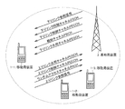
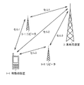
- a mobile station apparatus may be connected to the base station apparatus via a repeater as shown in FIG. In such a case, both or one of the reception timing of the downlink component carrier in the mobile station apparatus and the transmission timing to the base station apparatus for each uplink component carrier is different for each cell.
- the mobile station apparatus adjusts the transmission timing for each uplink component carrier of each cell and transmits data to the base station apparatus. There is a need.
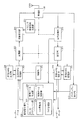
- FIG. 1 is a diagram illustrating a configuration of a mobile station apparatus according to an embodiment of the present invention.
- the mobile station apparatuses 1-1 to 1-3 include a radio unit 101, a transmission processing unit 103, a modulation unit 105, a transmission HARQ processing unit 107, a transmission HARQ storage unit 109, an uplink reference signal generation unit 111, and a random access preamble generation unit. 113, a reception processing unit 115, a demodulation unit 117, a reception HARQ processing unit 119, a reception HARQ storage unit 121, a control unit 123, and a mobile station management unit 125.
- the mobile station management unit 125 includes a UL scheduling unit 127, a control data creation unit 129, a control data analysis unit 131, a cell management unit 133, and a TAT management unit 135.
- Transmission HARQ processing unit 107 encodes input data in accordance with an instruction from the control unit 123, and performs puncture processing on the encoded data. Then, transmission HARQ processing section 107 outputs the punctured data to modulation section 105, and outputs the encoded data to transmission HARQ storage section 109. Also, when the transmission HARQ processing unit 107 is instructed to retransmit data by the control unit 123, (i) obtains encoded data from the transmission HARQ storage unit, and (ii) a puncture different from the previous puncture. Processing is performed, and (iii) punctured data is output to the modulation unit 105.
- the transmission HARQ storage unit 109 stores the data input from the transmission HARQ processing unit 107 and outputs the data stored in the transmission HARQ processing unit 107 according to an instruction from the transmission HARQ processing unit 107. In addition, the transmission HARQ storage unit 109 deletes the stored data in accordance with an instruction from the control unit 123.
- Modulation section 105 modulates input data from transmission HARQ processing section 107 and outputs the result to transmission processing section 103.
- the transmission processing unit 103 receives input data (or input signals) from the modulation unit 105, the uplink reference signal generation unit 111, and the random access preamble generation unit 113 in accordance with an instruction from the control unit 123 in the uplink of each cell.
- the mapped data is subjected to OFDM signal processing such as serial / parallel conversion, DFT-IFFT (Inverse Fast Fourier Transform) conversion, CP insertion, and so on. Generate a signal.
- the transmission processing unit 103 adjusts the transmission timing of the signal output for each uplink component carrier of each cell from the transmission timing information passed from the control unit 123, and after adjusting the transmission timing, transmits the OFDM signal to the radio unit 101. Output to.
- the uplink reference signal generation unit 111 generates an uplink reference signal from the uplink reference signal generation information acquired from the mobile station management unit 125 according to an instruction from the control unit 123, and transmits the generated uplink reference signal to the transmission processing unit 103. Output to.
- the random access preamble generation unit 113 generates a random access preamble from information regarding random access acquired from the mobile station management unit 125 according to an instruction from the control unit 123, and outputs the generated random access preamble to the transmission processing unit 103.
- the radio unit 101 up-converts the input signal from the transmission processing unit 103 to a radio frequency according to an instruction from the control unit 123 and transmits the radio signal from the transmission antenna.
- Radio section 101 down-converts the radio signal received from the antenna and outputs it to reception processing section 115.
- the reception processing unit 115 performs an FFT (Fast Fourier Transform) process on the input signal from the radio unit 101 and outputs the processed signal to the demodulation unit 117.
- Demodulation section 117 performs demodulation processing of input data and outputs the demodulated data to reception HARQ processing section 119.
- the reception HARQ processing unit 119 performs a decoding process on the input data.
- the reception HARQ processing unit 119 outputs control data to the mobile station management unit 125 and outputs user data to an upper layer.
- the reception HARQ processing unit 119 outputs the data that has failed in the decoding process to the reception HARQ storage unit 121 when the decoding process of the input data fails.
- reception HARQ processing section 119 When receiving the retransmission data, reception HARQ processing section 119 combines the data stored in reception HARQ storage section 121 with the retransmission data and performs a decoding process. Also, the reception HARQ processing unit 119 notifies the mobile station management unit 125 of the success or failure of the input data decoding process.
- the reception HARQ storage unit 121 stores the input data from the reception HARQ processing unit 119 and outputs the data stored in the reception HARQ processing unit 119 according to an instruction from the reception HARQ processing unit 119. Also, the reception HARQ storage unit 121 deletes the stored data in accordance with an instruction from the control unit 123.
- the control unit 123 includes a radio unit 101, a transmission processing unit 103, a modulation unit 105, a transmission HARQ processing unit 107, a transmission HARQ storage unit 109, an uplink reference signal generation unit 111, The random access preamble generation unit 113, the reception processing unit 115, the demodulation unit 117, the reception HARQ processing unit 119, and the reception HARQ storage unit 121 are controlled.
- the mobile station management unit 125 includes a UL scheduling unit 127, a control data creation unit 129, a control data analysis unit 131, a cell management unit 133, and a TAT management unit 135.
- the control data creation unit 129 creates an Ack / Nack message of data from the decoding result of the received data from the reception HARQ processing unit 119, and creates control data such as a message indicating downlink radio quality.
- the control data is output to the transmission HARQ processing unit 107.
- the control data analysis unit 131 analyzes the control data input from the reception HARQ processing unit 119.
- the control data analysis unit 131 outputs the cell system information, the cell allocation information, the random access response message, and the uplink reference signal generation information received from the base station apparatus 3 to the cell management unit 133 to transmit the transmission timing information and the transmission information.
- Timing timer information is output to the TAT management unit 135.
- the UL scheduling unit 127 includes a transmission processing unit 103, a modulation unit 105, a control unit 123 based on the uplink data scheduling information from the base station apparatus 3 or the transmitted uplink data response (ACK / NACK).
- the transmission HARQ processing unit 107 is controlled. Further, the cell management unit 133 is instructed to perform random access based on the control information from the upper layer.
- the cell management unit 133 manages the cells allocated from the base station device 3.
- the cell management unit 133 includes: (i) a physical channel configuration for each cell received from the base station device 3, transmission power information, information on random access, and (ii) uplink reference signal generation information. It manages radio resources individually allocated to the mobile station apparatus 1-1, such as information, radio resources of uplink reference signals (measurement reference signals), radio resources of the uplink control channel PUCCH, and the like.
- the cell management unit 133 notifies the random access preamble generation unit 113 of information related to random access via the control unit 123, and notifies the uplink reference signal generation unit 111 of the generation information of the uplink reference signal.
- the cell management unit 133 instructs the random access preamble generation unit 113 via the control unit 123 to transmit the random access preamble to the base station apparatus 3 at the start of communication or when making a schedule request for uplink data. .
- the cell management unit 133 When notified from the TAT management unit 135 that the transmission timing timer has expired, the cell management unit 133, via the control unit 123, (i) stops the HARQ process of the cell whose transmission timing has expired to the transmission HARQ processing unit 107 (Ii) Instruct the transmission HARQ storage unit 109 to erase data stored in the cell whose transmission timing has expired, and (iii) Uplink the cell whose transmission timing has expired to the uplink reference signal generation unit 111 Instructs to stop the generation of the link reference signal. In addition, the cell management unit 133 releases the radio resources of the uplink control channel PUCCH and the radio resources of the uplink reference signal (measurement reference signal) allocated from the base station apparatus 3 of the cell whose transmission timing has expired.
- the TAT management unit 135 manages the transmission timing and transmission timing timer for each cell. In addition, the TAT management unit 135 manages cell-related information having the same transmission timing.
- the TAT management unit 135 When acquiring the transmission timing information, the TAT management unit 135 notifies the transmission processing unit 103 of the transmission timing information of the acquired cell and the cell information for updating the transmission timing via the control unit 123, and starts the transmission timing timer. Or restart. Then, the TAT management unit 135 notifies the cell management unit 133 that the transmission timing timer has been started or restarted for each cell. Also, when the transmission timing timer expires for each cell, the TAT management unit 135 notifies the cell management unit 133 that the transmission timing timer of the target cell has expired.
- FIG. 2 shows a configuration diagram of the base station apparatus 3 according to the embodiment of the present invention.
- the base station apparatus 3 includes a radio unit 201, a transmission processing unit 203, a modulation unit 205, a transmission HARQ processing unit 207, a transmission HARQ storage unit 209, a downlink reference signal generation unit 211, a preamble detection unit 213, a reception processing unit 215, and a demodulation. 217, reception HARQ processing unit 219, reception HARQ storage unit 221, control unit 223, and base station management unit 225.
- the base station management unit 225 includes a DL / UL schedule unit 227, a control data creation unit 229, a control data analysis unit 231, a cell management unit 233, and a TAT management unit 235.
- Transmission HARQ processing unit 207 User data and control data are input to the transmission HARQ processing unit 207.
- the transmission HARQ processing unit 207 performs encoding on the input data and performs puncture processing on the encoded data according to an instruction from the control unit 223. Then, transmission HARQ processing section 207 outputs the punctured data to modulation section 205, and outputs the encoded data to transmission HARQ storage section 209.
- the transmission HARQ processing unit 207 when instructed to retransmit data by the control unit 223, (i) acquires encoded data from the transmission HARQ storage unit, and (ii) performs puncture processing different from the puncture performed previously. (Iii) The punctured data is output to the modulation unit 205.
- the transmission HARQ storage unit 209 stores the input data from the transmission HARQ process 207 and outputs the data stored in the transmission HARQ processing unit 207 according to an instruction from the transmission HARQ process 207. Further, the transmission HARQ storage unit 209 deletes the stored data in accordance with an instruction from the control unit 223.
- the modulation unit 205 modulates the input data from the transmission HARQ processing unit 207 and outputs it to the transmission processing unit 203.
- the transmission processing unit 203 (i) receives input data (or signals) from the modulation unit 205 and the downlink reference signal generation unit 211 in accordance with an instruction from the control unit 223, the downlink control channel PDCCH of the downlink component carrier of each cell, Mapping to each channel such as downlink synchronization channel DSCH, broadcast channel PBCH, downlink shared channel PDSCH, (ii) serial / parallel conversion, IFFT (Inverse Fast Fourier Transform) conversion, OFDM signal processing such as CP insertion is performed to generate an OFDM signal. Then, the transmission processing unit 203 outputs the generated OFDM signal to the wireless unit 201.
- the radio unit 201 up-converts the input signal from the transmission processing unit 203 to a radio frequency according to an instruction from the control unit 223, and transmits the radio signal to the mobile station apparatuses 1-1 to 1-3 from the transmission antenna.
- Radio section 201 receives a radio signal from mobile station apparatus 1-1 from an antenna, down-converts the received signal into a baseband signal, and converts the received signal to reception processing section 215 or preamble detection section 213. Output.
- the reception processing unit 215 performs FFT (Fast Fourier Transform) processing on the input signal from the wireless unit 201 and outputs the result to the demodulation unit 217.
- FFT Fast Fourier Transform
- the reception processing unit 215 measures the radio channel quality and the transmission timing deviation amount from the uplink reference signal (measurement reference signal), and passes the measurement result to the base station management unit 225.
- the uplink communication scheme is assumed to be a single carrier scheme such as DFT-spread OFDM, but a multicarrier scheme such as the OFDM scheme may be used.
- Demodulation section 217 performs demodulation processing of input data and outputs the demodulated data to reception HARQ processing section 219.
- the reception HARQ processing unit 219 performs a decoding process on the input data.
- the reception HARQ processing unit 219 outputs the control data to the base station management unit 225 and outputs the user data to the upper layer.
- the reception HARQ processing unit 219 outputs the data that has failed in the decoding process to the reception HARQ storage unit 221 when the decoding process of the input data fails.
- the reception HARQ processing unit 219 When receiving the retransmission data, the reception HARQ processing unit 219 combines the data stored in the reception HARQ storage unit 221 and the retransmission data, and performs a decoding process.
- reception HARQ processing unit 219 notifies the base station management unit 225 of the success or failure of the input data decoding process.
- the reception HARQ storage unit 221 stores input data from the reception HARQ storage unit, and outputs the data stored in the reception HARQ processing unit 219 according to an instruction from the reception HARQ processing 219. Further, the reception HARQ storage unit 221 deletes the stored data in accordance with an instruction from the control unit 223.
- the preamble detection unit 213 performs a correlation process on the input signal from the radio unit 201 and performs a random access preamble detection process. When detecting a random access preamble, the preamble detection unit 213 calculates a transmission timing shift amount from the detected random access preamble. The preamble detection unit 213 notifies the base station management unit 225 of the cell in which the random access preamble is detected, the information on the detected preamble, and the transmission timing shift amount.
- the control unit 223 includes a radio unit 201, a transmission processing unit 203, a modulation unit 205, a transmission HARQ processing unit 207, a transmission HARQ storage unit 209, a downlink reference signal generation unit 211, The reception processing unit 215, the demodulation unit 217, the reception HARQ processing unit 219, and the reception HARQ storage unit 221 are controlled.
- the base station management unit 225 includes a DL / UL schedule unit 227 that performs downlink and uplink schedules, a control data creation unit 229, a control data analysis unit 231, a cell management unit 233, and a TAT management unit 235.
- the DL / UL schedule unit 227 is a control created by the downlink radio channel quality information notified from the mobile station apparatus 1-1 or the data information of each user notified from the higher layer or the control data generating unit 229. A schedule for mapping user data and control data from the data to each downlink channel is performed, and the schedule result is passed to the control unit 223.
- the DL / UL schedule unit 227 maps user data to each uplink channel from the uplink radio channel quality result from the reception processing unit 215 and the radio resource allocation request from the mobile station apparatus 1-1. Schedule. Also, when notified from the preamble detector 213 that the random access preamble is detected, the DL / UL schedule unit 227 allocates the uplink shared channel PUSCH, and assigns the allocated uplink shared channel PUSCH and preamble number to the control data. The creation unit 229 is notified.
- the DL / UL schedule unit 227 When the DL / UL schedule unit 227 is notified of the transmission timing information from the TAT management unit 235, the DL / UL schedule unit 227 notifies the mobile station device 1-1 of the transmission timing information from the downlink and uplink schedule status of the mobile station device 1-1. Judge whether to do. When notifying the transmission timing information, the DL / UL scheduling unit 227 reports the transmission timing information to the TAT management unit 235 and notifies the control data creation unit 229 of the transmission timing information.
- the control data creation unit 229 creates control data arranged on the downlink control channel PDCCH and control data arranged on the downlink shared channel PDSCH.
- the control data creation unit 229 includes (i) a control message including schedule information, an uplink data response (ACK / NACK), (ii) physical channel configuration information, transmission power information of each channel, and information on random access. (Iii) Initial setting message including cell setting information (including information related to random access), (iv) Random access response including preamble number, transmission timing information, and scheduling information Control data such as a message, (v) a contention resolution message, and (vi) a transmission timing message including transmission timing information are created.
- the control data analysis unit 231 controls the transmission HARQ processing unit 207 via the control unit 223 according to the downlink data response (Ack / Nack) result from the mobile station apparatus 1-1.
- the cell management unit 233 manages each cell and system information of each cell (physical channel configuration information, transmission power information of each channel, information on random access, cell relation information of transmission timing, etc.). Further, the cell management unit 233 assigns one or more cells to the mobile station apparatuses 1-1 to 1-3. Also, the cell management unit 233 allocates radio resources for the uplink reference signal (measurement reference signal) and radio resources for the uplink control channel PUCCH. Then, the cell management unit 233 passes the cell allocation information, the cell system information, the allocated radio resource information, and the like to the control data creation unit 229 so as to notify the information about the allocated cell.
- the cell management unit 233 (i) stops the HARQ processing of the cell whose transmission timing has expired, via the control unit 223, to the transmission HARQ processing unit 207 (Ii)
- the transmission HARQ storage unit 209 is instructed to delete data stored in a cell whose transmission timing has expired, and (iii) an uplink reference signal assigned to the mobile station apparatus 1-1 (for measurement) The radio resource of the reference signal) and the radio resource of the uplink control channel PUCCH are released.
- the TAT management unit 235 manages the transmission timing and transmission timing timer for each cell of the mobile station apparatuses 1-1 to 1-3. In addition, the TAT management unit 235 manages cell-related information having the same transmission timing.
- the TAT management unit 235 acquires the transmission timing shift amount from the preamble detection unit 213 or the reception processing unit 215, the TAT management unit 235 creates transmission timing information and notifies the DL / UL scheduling unit 227 of the transmission timing information.
- the TAT management unit 235 is notified of transmission of transmission timing information from the cell management unit 233, the TAT management unit 235 starts or restarts the transmission timing timer. In addition, when the transmission timing timer expires for each cell, the TAT management unit 235 notifies the cell management unit 233 that the transmission timing timer of the target cell has expired.
- a radio communication system is assumed in which the base station apparatus described in FIG. 11 and FIG. 12 allocates a plurality of cells to the mobile station apparatus, and the base station apparatus and the mobile station apparatus communicate with each other through the allocated cells. Further, a wireless communication system is assumed in which communication is performed via a plurality of cells having different transmission timings from the mobile station apparatus described in FIG.
- the base station apparatus allocates, for each frequency, one or more cells having different frequencies that match the communication capability and communication conditions of the mobile station apparatus from among a plurality of cells. Then, the mobile station apparatus transmits / receives data to / from the base station apparatus via the assigned cell.
- a mobile station apparatus communicates with a base station apparatus using a plurality of cells, it may be connected to the base station apparatus via a repeater as shown in FIG. In such a case, the reception timing of data from the downlink component carrier in the mobile station apparatus may be different for each cell.
- the transmission timing to the base station apparatus may be different for each uplink component carrier of each cell. When the transmission timing to the base station apparatus differs for each uplink component carrier, the mobile station apparatus needs to adjust the transmission timing for each uplink component carrier of each cell.
- the transmission timing is adjusted for each uplink component carrier of each cell, the transmission timing is updated for each cell or the transmission timing becomes invalid. For this reason, it is necessary to efficiently update the transmission timing or consider an efficient operation of the mobile station when the transmission timing becomes invalid.
- the base station apparatus groups cells having the same transmission timing from the mobile station apparatus (hereinafter, the grouped cells are referred to as “transmission timing cell group”). Then, the base station apparatus sets one cell as the first cell and sets the other cells as the second cell. The base station device further permits random access to one cell in each transmission timing cell group for one cell in the transmission timing cell group, and the transmission timing information also includes the transmission timing cell group. Transmit to one of the cells. Further, the base station apparatus and the mobile station apparatus manage the transmission timing by having one transmission timing timer for each transmission timing cell group. By doing in this way, the base station apparatus and the mobile station apparatus can efficiently manage the transmission timing and the transmission timing timer.
- the mobile station apparatus stops the uplink transmission process for all cells.
- the mobile station apparatus stops the uplink transmission processing for the cells of the transmission timing cell group whose transmission timing timer has expired. To do.
- the mobile station apparatus transmits a transmission timing cell group (for example, the first timing cell group different from the transmission timing cell group for which the transmission timing timer has expired).
- the uplink transmission process is not stopped for the cells in the transmission timing cell group including the first cell.
- a transmission timing cell group (referred to as a first transmission timing cell group as appropriate for convenience of explanation) composed of cell groups including the first cell
- the mobile station only when the transmission timing timer of the first transmission timing cell group expires The apparatus stops the uplink transmission process for the cells of the first transmission timing cell group.
- the mobile station apparatus transmits the first transmission timing cell
- the uplink transmission process is not stopped for the cells in the group.
- the mobile station device when the transmission timing timer of the same second transmission timing cell group expires or when the transmission timing timer of the first transmission timing cell group expires, the mobile station device The uplink transmission process is stopped for the cells of the transmission timing cell group.
- the mobile station device does not stop the uplink transmission process for the cells of the same second transmission timing cell group.
- the base station apparatus when the base station apparatus and the mobile station apparatus perform notification via the cells of a plurality of transmission timing cell groups, the base station apparatus considers the amount of data from the mobile station apparatus, etc.
- the transmission timing information of the timing cell group is notified or the notification is stopped.
- the base station apparatus makes the transmission timing valid / invalid by continuing or stopping the transmission timing timer.
- the transmission unit control of the mobile station apparatus by the base station apparatus becomes possible.
- the uplink transmission is stopped by transmitting an uplink control channel PUCCH other than transmission of a random access preamble, transmitting an uplink shared channel PUSCH, and transmitting an uplink reference signal (a reference signal for measurement and a reference signal for demodulation). Indicates stoppage.
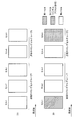
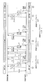
- the base station apparatus 3 includes cells 1 to 5 as shown in FIG. 3A, and the cells 1 to 3 are transmission timing cell groups having the same transmission timing. Assume that cell 5 is a transmission timing cell group having the same transmission timing.
- the mobile station apparatus 1-1 performs a cell search and finds one cell of the base station apparatus 3. Here, it is assumed that the mobile station apparatus 1-1 finds the cell 1.
- the mobile station apparatus 1-1 receives the broadcast channel PBCH of the cell 1, and acquires system information (cell physical channel configuration, transmission power information, information on random access, etc.). Then, the mobile station apparatus 1-1 transmits a random access preamble to the random access channel RACH of the cell 1 for initial access using information on random access included in the system information. Then, the mobile station apparatus 1-1 acquires (i) random access response information including transmission timing information for the cell 1 from the base station apparatus 3, and (ii) sets uplink component carrier transmission timing for the cell 1. Then, (iii) start the transmission timing timer.
- the mobile station apparatus 1-1 transmits the message 3 to the base station apparatus 3 via the cell 1.
- the mobile station apparatus 1-1 transmits the message 3 including the contents indicating the initial access in the message 3.
- the mobile station apparatus 1-1 receives the contention resolution from the base station apparatus 3, the mobile station apparatus 1-1 ends the contention based random access procedure.
- the base station device 3 allocates a cell to be used by the mobile station device 1-1 and notifies a cell that permits random access for each first cell and transmission timing cell group.
- the base station apparatus 3 assigns cells 1 to 5 to the mobile station apparatus 1-1, cell 1 is the first cell, and cells 2 to 5 are the second cell. Set to. The base station device 3 sets the cell 1 and the cell 5 to permit random access.
- the base station apparatus 3 (i) system information and cell timing group information of the cell allocated to the mobile station apparatus 1-1, (ii) uplink control channel PUCCH allocation information of the first cell, ( iii) Generation information of an uplink reference signal (measurement reference signal) and radio resource allocation information for transmitting an uplink reference signal (measurement reference signal), (iv) Radio resources of a periodic uplink shared channel PUSCH Setting information such as allocation information is also notified to the mobile station apparatus 1-1.
- the mobile station device 1-1 uses the same transmission timing as the cell 1 as the uplink transmission timing of the cell 2 and the cell 3 of the cell group.
- the transmission timing of cell 1 is set. Thereafter, data is exchanged between the mobile station apparatus 1-1 and the base station apparatus 3 via the downlink component carriers of cells 1 to 5 and the uplink component carriers of cells 1 to 3.
- the base station apparatus 3 When the amount of transmission data from the mobile station apparatus 1-1 increases and there is a cell that is not used by the mobile station apparatus 1-1, the base station apparatus 3 performs non-contention based random access to the cell for which random access is permitted. Random access instruction information for instructing access is notified by the downlink control channel PDCCH. Here, the base station apparatus 3 notifies the mobile station apparatus 1-1 of random access instruction information for the cell 5.
- the random access instruction information includes a preamble number and a random access channel number.
- the mobile station apparatus 1-1 confirms the preamble number, and if the preamble number indicates non-contention based random access, the mobile station apparatus 1-1 uses the preamble and random access channel specified by the base station apparatus 3 and uses the random access preamble. Is transmitted to the random access channel RACH of the cell 5.
- the base station device 3 When the base station device 3 detects the random access preamble, it calculates transmission timing information from the random access preamble, and the mobile station device 1-1 receives the random access including the transmission timing information via the downlink component carrier of the cell 5. Notify the response.
- the mobile station apparatus 1-1 sets the transmission timing included in the random access response as the uplink transmission timing of the cell 5.
- the mobile station apparatus 1-1 further sets the uplink transmission timing of the cell 4 that is the same transmission timing cell group, and starts the transmission timing timer. Then, the mobile station apparatus 1-1 completes the non-contention based random access procedure. Thereafter, data is exchanged between the mobile station apparatus 1-1 and the base station apparatus 3 including the uplink component carriers of the cells 4 and 5.
- the mobile station apparatus 1-1 has one transmission timing timer for each transmission timing cell group, and starts or restarts the transmission timing timer when receiving the transmission timing information.
- the base station apparatus 3 has one transmission timing timer for each transmission timing cell group, and when the transmission timing information is transmitted, the transmission timing timer is started or restarted. While the transmission timing timer is in operation, uplink synchronization is in effect (transmission timing is valid), and the mobile station apparatus 1-1 transmits an uplink on an uplink component carrier of the target transmission timing cell group. Transmission is possible.
- the transmission timing timer may be configured to be provided for each cell.
- the base station apparatus 3 measures the uplink reference signal from the mobile station apparatus 1-1 and calculates transmission timing information. When it is necessary to maintain the transmission timing, the base station device 3 notifies the mobile station device 1-1 of the transmission timing information.
- the mobile station device 1-1 When the transmission timing timer of the transmission timing cell group including the first cell expires, the mobile station device 1-1 (i) transmits the transmission timing cell group (cell 4, cell 5) configured only by the second cell. Stop the timing timer, and (ii) restrict uplink transmission other than random access preamble transmission in the first cell to all cells (cell 1, cell 2, cell 3, cell 4, cell 5), (iii) ) All data stored in the transmission HARQ storage unit 109 (hereinafter referred to as a transmission HARQ buffer) is deleted. Then, the mobile station apparatus 1-1 performs measurement allocated to the radio resources of the allocated uplink control channel PUCCH and all cells (cell 1, cell 2, cell 3, cell 4, cell 5). Release the radio resources of the reference signal for use. Also, when downlink and uplink allocation information is acquired, the mobile station apparatus 1-1 discards all downlink shared channel PDSCH allocation information and uplink shared channel PUSCH allocation information.
- the base station device 3 When the transmission timing timer of the transmission timing cell group including the first cell expires, the base station device 3 (i) transmits the transmission timing cell group (cell 4, cell 5) configured only by the second cell. Stop timing timer, (ii) stop allocation of uplink shared channel PUSCH to all cells of mobile station apparatus 1-1, and (iii) receive HARQ storage unit 221 (hereinafter referred to as receive HARQ buffer) ))) Erase all data stored in it. Then, the base station apparatus 3 releases the radio resource of the uplink control channel PUCCH allocated to the mobile station apparatus 1-1 and the radio resource of the measurement reference signal allocated to all cells.
- the base station apparatus 3 releases the radio resource of the uplink control channel PUCCH allocated to the mobile station apparatus 1-1 and the radio resource of the measurement reference signal allocated to all cells.
- the mobile station apparatus 1-1 When the transmission timing timer of the transmission timing cell group composed only of the second cell expires, the mobile station apparatus 1-1 includes the cells (cell 4 and cell 5) included in the transmission timing cell group whose transmission timing timer has expired. Uplink transmission is stopped, and data for cells included in the transmission timing cell group whose transmission timing timer stored in the transmission HARQ buffer has expired is erased. The mobile station apparatus 1-1 releases the radio resource of the reference signal for measurement assigned to the cell included in the transmission timing cell group whose transmission timing timer has expired. Further, when the mobile station apparatus 1-1 has acquired downlink and uplink assignment information, the mobile station apparatus 1-1 assigns the uplink shared channel PUSCH to the cells included in the transmission timing cell group whose transmission timing timer has expired. Discard information.
- the base station device 3 when the transmission timing timer of the transmission timing cell group configured by only the second cell expires, the base station device 3 includes cells (cell 4 and cell 5) included in the transmission timing cell group whose transmission timing timer has expired. The allocation of the uplink shared channel PUSCH to is stopped, and the data for the cells included in the transmission timing cell group whose transmission timing timer stored in the reception HARQ storage unit 221 has expired is erased. Then, the base station apparatus 3 releases the radio resources of the measurement reference signal allocated to the cells included in the transmission timing cell group for which the transmission timing timer allocated to the mobile station apparatus 1-1 has expired.
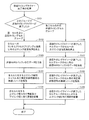
- FIG. 4 shows a processing flowchart of the mobile station device 1-1 when the transmission timing timer expires.
- the mobile station apparatus 1-1 checks which transmission timing cell group the transmission timing timer has expired (step S101).
- the mobile station apparatus 1-1 stops the transmission timing timer of the transmission timing cell group configured only by the second cell.
- the uplink transmission processing other than the random access preamble transmission in the first cell is stopped for all cells (step S102).
- the mobile station apparatus 1-1 deletes all data stored in the transmission HARQ buffer (step S103).
- the mobile station apparatus 1-1 releases the radio resource of the assigned uplink control channel PUCCH and the radio resource of the measurement reference signal assigned to all the cells (step 104). Further, when the radio resource of the periodic uplink shared channel PUSCH is assigned to the mobile station apparatus 1-1, the radio resource is also released.
- the mobile station apparatus 1-1 when acquiring the downlink and uplink allocation information, discards all the downlink shared channel PDSCH allocation information and the uplink shared channel PUSCH allocation information (step S105). ). Note that while the transmission timing is invalid in the transmission timing cell group including the first cell, the mobile station apparatus 1-1 may perform processing for detecting the uplink allocation information notified by the downlink control channel PDCCH. However, when uplink allocation information is detected, the mobile station apparatus 1-1 discards the acquired uplink allocation information. Note that the mobile station apparatus 1-1 also transmits a data response to the base station apparatus 3 even when data is received on the downlink shared channel PDSCH until the transmission timing becomes valid in the transmission timing cell group including the first cell. (Ack / Nack) is not returned.
- the radio resources of the uplink control channel PUCCH for data response (Ack / Nack) in the uplink control channel PUCCH allocated from the base station apparatus 3 may not be released. In this case, when uplink synchronization is resumed again, the mobile station apparatus 1-1 can immediately return a response to the downlink data to the base station apparatus 3.
- the mobile station apparatus 1-1 sets the cell included in the transmission timing cell group for which the transmission timing timer has expired. Then, the uplink transmission process is stopped (step S106). Also in this case, the mobile station apparatus 1-1 can transmit a random access preamble. Then, the mobile station device 1-1 deletes data for cells included in the transmission timing cell group whose transmission timing timer stored in the transmission HARQ buffer has expired (step S107). The mobile station apparatus 1-1 releases the radio resource of the reference signal for measurement assigned to the cell included in the transmission timing cell group whose transmission timing timer has expired (step S108).
- the mobile station apparatus 1-1 assigns the uplink shared channel PUSCH to the cells included in the transmission timing cell group whose transmission timing timer has expired. Information is discarded (step S109). Note that the mobile station apparatus 1-1 may perform detection processing of uplink allocation information notified by the downlink control channel PDCCH for cells included in the transmission timing cell group whose transmission timing timer has expired. However, when the uplink allocation information is detected, the mobile station apparatus 1-1 discards the acquired uplink allocation information.
- the mobile station apparatus 1-1 receives data on the downlink shared channel PDSCH, A data response (Ack / Nack) is returned to the base station apparatus 3 using the radio resource of the uplink control channel PUCCH.
- FIG. 5 shows a processing flowchart of the base station apparatus 3 when the transmission timing timer expires.
- the base station device 3 confirms which transmission timing cell group the transmission timing timer has expired (step S201).
- the transmission timing cell group for which the transmission timing timer has expired is a transmission timing cell group including the first cell
- the base station device 3 stops the transmission timing timer for the transmission timing cell group composed of only the second cell
- the allocation process of the uplink shared channel PUSCH of the mobile station apparatus 1-1 is stopped (step S202).
- the base station apparatus 3 deletes all data stored in the reception HARQ buffer (step S203).
- the base station apparatus 3 releases the radio resource of the uplink control channel PUCCH allocated to the mobile station apparatus 1-1 and the radio resource of the measurement reference signal allocated to all the cells (step 204).
- the radio resources of the uplink control channel PUCCH for data response (Ack / Nack) in the uplink control channel PUCCH allocated by the base station device 3 to the mobile station device 1-1 should not be released. May be. In this case, when uplink synchronization is resumed again, the mobile station apparatus 1-1 can immediately return a response to the downlink data to the base station apparatus 3.
- the base station device 3 When the transmission timing cell group for which the transmission timing timer has expired is a transmission timing cell group configured by only the second cell, the base station device 3 performs the operation for the cells included in the transmission timing cell group for which the transmission timing timer has expired.
- the uplink shared channel PUSCH allocation process is stopped (step S205).
- the base station device 3 erases data for cells included in the transmission timing cell group whose transmission timing timer stored in the reception HARQ buffer has expired (step S206).
- the base station apparatus 3 releases the radio resources of the measurement reference signal assigned to the cells included in the transmission timing cell group whose transmission timing timer has expired (step S207).
- the base station apparatus when the base station apparatus and the mobile station apparatus perform notification via the cells of a plurality of transmission timing cell groups, the base station apparatus considers the data amount from the mobile station apparatus and the like. Thus, the transmission timing information of each transmission timing cell group is notified or the notification is stopped. Thereby, the base station apparatus makes the transmission timing valid / invalid by continuing or stopping the transmission timing timer. This enables efficient transmission control of the mobile station apparatus by the base station apparatus.
- the mobile station apparatus 1-1 when the transmission timing timer of the transmission timing cell group including the first cell expires, the mobile station apparatus 1-1 further stops downlink reception processing for all the second cells, and receives HARQ. Erases data for all second cells stored in the buffer. Then, when the transmission timing timer of the transmission timing cell group composed only of the second cell expires, the mobile station apparatus 1-1 performs the downlink reception process for the cells of the transmission timing cell group whose transmission timing timer has expired. The data stored in the reception HARQ buffer of the cell of the transmission timing cell group that has stopped and whose transmission timing timer has expired may be erased.
- the mobile station apparatus 1-1 and the base station apparatus 3 of the embodiment have been described using functional block diagrams, but the functions of the respective units of the mobile station apparatus 1-1 and the base station apparatus 3 or these
- a program for realizing a part of the above functions is recorded on a computer-readable recording medium, and the program recorded on the recording medium is read into a computer system and executed, whereby the mobile station apparatus and the base station apparatus Control may be performed.
- the “computer system” here includes an OS (Operating System) and hardware such as peripheral devices.
- Computer-readable recording medium means a portable medium such as a flexible disk, a magneto-optical disk, a ROM (Read Only Memory), a CD (Compact Disk) -ROM, or a hard disk built in a computer system. Refers to the device. Furthermore, the “computer-readable recording medium” means that a program is dynamically held for a short time, like a communication line when a program is transmitted via a network such as the Internet or a communication line such as a telephone line. In this case, it is intended to include those that hold a program for a certain period of time, such as a volatile memory inside a computer system serving as a server or a client in that case.
- the program may be a program for realizing a part of the functions described above, and may be a program capable of realizing the functions described above in combination with a program already recorded in a computer system. .
- each functional block used in each of the above embodiments may be realized as an LSI that is typically an integrated circuit.
- Each functional block may be individually formed into chips, or a part or all of them may be integrated into a chip.
- the method of circuit integration is not limited to LSI, and may be realized by a dedicated circuit or a general-purpose processor.
- an integrated circuit based on the technology can also be used.
Landscapes
- Engineering & Computer Science (AREA)
- Computer Networks & Wireless Communication (AREA)
- Signal Processing (AREA)
- Mobile Radio Communication Systems (AREA)
Abstract
Advanced-EUTRAシステムに対して、移動局装置の効率の良い送信制御を可能とする。基地局装置が複数セルを割り当て、基地局装置と複数セルを介して通信を行なう移動局装置において、複数セルは、1つの第一セルと同じ上りリンク送信タイミングのセルから構成される第一のグループと、1つ以上の前記第一セルと異なる上りリンク送信タイミングのセルから構成される第二のグループとにグループ化される。グループ毎に送信タイミングタイマーを用いて前記上りリンク送信タイミングは管理される。第一のグループの送信タイミングタイマーが満了した場合、移動局装置は、複数のセルに対する全ての上りリンク送信を停止する。第二のグループの送信タイミングタイマーが満了した場合、移動局装置は、送信タイミングタイマーが満了した第二のグループのセルに対する上りリンク送信を停止する。
Description
本発明は、基地局装置、移動局装置および無線通信システムに関連し、より詳細には、上りリンクの送信タイミングが無効になった場合の動作における移動局装置、基地局装置、無線通信システム、制御方法及び集積回路に関する。
3GPP(3rd Generation Partnership Project)では、W-CDMA方式が第三世代セルラー移動通信方式として標準化され、順次サービスが開始されている。また、通信速度を更に上げたHSDPAも標準化され、サービスが開始されている。
一方、3GPPでは、第三世代無線アクセスの進化(Evolved Universal Terrestrial Radio Access;以下、「EUTRA」と呼称する。)の標準化が進められている。EUTRAの下りリンクの通信方式として、マルチパス干渉に強く、高速伝送に適したOFDM(Orthogonal Frequency Division Multiplexing)方式が採用されている。また、上りリンクの通信方式として、移動局装置のコストと消費電力を考慮し、送信信号のピーク対平均電力比PAPR(Peak to Average Power Ratio)を低減できるシングルキャリア周波数分割多重方式SC-FDMA(Single Carrier-Frequency Division Multiple Access)のDFT(Discrete Fourier Transform(離散フーリエ変換))-spread OFDM方式が採用されている。
また、3GPPでは、EUTRAの更なる進化のAdvanced-EUTRAの議論も始まっている。Advanced-EUTRAでは、上りリンクおよび下りリンクでそれぞれ最大100MHz帯域幅までの帯域を使用して、最大で下りリンク1Gbps以上、上りリンク500Mbps以上の伝送レートの通信を行なうことを想定している。
Advanced-EUTRAでは、EUTRAの移動局装置も収容できるようにEUTRAの20MHz以下の帯域を複数個束ねることで、最大で100MHz帯域を実現することを考えている。尚、Advanced-EUTRAでは、EUTRAの1つの20MHz以下の帯域を「コンポーネントキャリア(Component Carrier:CC)」と呼んでいる(後述する非特許文献2)。また、1つの下りリンクのコンポーネントキャリアと1つの上りリンクのコンポーネントキャリアとを組み合わせて1つのセルが構成される。尚、1つの下りリンクコンポーネントキャリアのみでも1つのセルを構成できる。基地局装置は、移動局装置に複数セルを割り当てて、割り当てたセルを介して移動局装置と通信を行なう。
3GPP TS(Technical Specification)36.300、V9.40(2010-06)、Evolved Universal Terrestrial Radio Access(E-UTRA) and Evolved Universal Terrestrial Radio Access Network(E-UTRAN)、Overall description Stage2
3GPP TR(Technical Specification)36.814、V9.00(2010-03)、Evolved Universal Terrestrial Radio Access(E-UTRA) Further advancements for E-UTRA physical layer aspects
移動局装置が、複数のセルを使用して基地局装置と通信を行なう場合、リピータ(Repeater)などを介して基地局装置へ接続する場合がある。このような場合、移動局装置での下りリンクコンポーネントキャリアからのデータの受信タイミングは、セル毎に異なることとなる。更に、各セルの上りリンクコンポーネントキャリア毎に基地局装置への送信タイミングも異なることとなる。その為、移動局装置は、各セルの上りリンクコンポーネントキャリア毎、または、送信タイミングが同じコンポーネントキャリアのグループ毎に送信タイミングの調整を行なって、基地局装置へのデータ送信を行なう必要がある。
また、各セルの上りリンクコンポーネントキャリア毎、または、送信タイミングが同じコンポーネントキャリアのグループ毎に送信タイミングの調整が必要なことから、移動局装置は、各セルの上りリンクコンポーネントキャリア毎、または、送信タイミングが同じコンポーネントキャリアのグループ毎に送信タイミングの有効期間を示す送信タイミングタイマーを持つ必要がある。
しかしながら、移動局装置が各セルの上りリンクコンポーネントキャリア毎に送信タイミングの調整を行なう為、セル毎に送信タイミングが更新されたり、送信タイミングが無効になったりする。その為、送信タイミングの更新を行なったり、送信タイミングが無効になった場合における移動局装置の効率的な動作を考える必要がある。
本発明は、このような事情に鑑みてなされたものであり、上りリンクコンポーネントキャリア毎に移動局装置からのデータ送信の送信タイミングが異なる場合について、効率の良い移動局装置の送信制御を可能とする移動局装置、基地局装置、無線通信システム、制御方法及び集積回路を提供することを目的とする。
(1)上記の目的を達成するために、本発明は、以下のような手段を講じた。すなわち、本発明の移動局装置は、基地局装置が複数セルを割り当て、前記基地局装置と前記複数セルを介して通信を行なう移動局装置であって、前記複数セルは1つの第一セルと同じ上りリンク送信タイミングのセルから構成される第一のグループと1つ以上の前記第一セルと異なる上りリンク送信タイミングのセルから構成される第二のグループとにグループ化され、前記グループ毎に送信タイミングタイマーを用いて前記上りリンク送信タイミングは管理され、前記第一のグループの送信タイミングタイマーが満了した場合、前記複数のセルに対する全ての上りリンク送信を停止し、前記第二のグループの送信タイミングタイマーが満了した場合、前記送信タイミングタイマーが満了した第二のグループのセルに対する上りリンク送信を停止することを特徴とする。
(2)また、本発明の移動局装置は、前記第一のグループの送信タイミングタイマーが満了した場合、前記複数のセルに対応する全ての送信HARQバッファのデータを消去し、前記第二のグループの送信タイミングタイマーが満了した場合、前記送信タイミングタイマーが満了した第二のグループのセルに対応する送信HARQバッファのデータを消去することを特徴とする。
(3)また、本発明の移動局装置は、前記第一のグループの送信タイミングタイマーが満了した場合、前記複数のセルに割り当てられている測定用参照信号の無線リソースを解放し、前記第二のグループの送信タイミングタイマーが満了した場合、前記送信タイミングタイマーが満了した第二のグループのセルに割り当てられている測定用参照信号の無線リソースを解放することを特徴とする。
(4)また、本発明の移動局装置は、前記第一のグループの送信タイミングタイマーが満了した場合、全ての上りリンク共用チャネル及び下りリンク共用チャネルの割り当て情報を破棄し、第二のグループの送信タイミングタイマーが満了した場合、前記送信タイミングタイマーが満了した第二のグループのセルに割り当てられている上りリンク共用チャネルの割り当て情報を破棄することを特徴とする。
(5)また、本発明の基地局装置は、移動局装置が複数セルを割り当てられ、前記移動局装置と前記セルを介して通信を行なう基地局装置であって、前記複数セルは1つの第一セルと同じ上りリンク送信タイミングのセルから構成される第一のグループと1つ以上の前記第一セルと異なる上りリンク送信タイミングのセルから構成される第二のグループとにグループ化され、前記グループ毎に送信タイミングタイマーを用いて前記上りリンク送信タイミングは管理され、前記第一のセルを含む前記グループの送信タイミングタイマーが満了した場合、前記複数のセルに対する上りリンク共用チャネルの割り当て処理を停止し、前記第二のグループの送信タイミングタイマーが満了した場合、前記送信タイミングタイマーが満了した第二のグループのセルに対する上りリンク共用チャネルの割り当て処理を停止することを特徴とする。
(6)また、本発明の基地局装置は、前記第一のグループの送信タイミングタイマーが満了した場合、前記移動局装置に割り当てた前記複数のセルに対応する受信HARQバッファの全データを消去し、前記第二のグループの送信タイミングタイマーが満了した場合、前記第二のグループのセルに対応する受信HARQバッファのデータを消去することを特徴とする。
(7)また、本発明の基地局装置は、前記第一のグループの送信タイミングタイマーが満了した場合、前記移動局装置の前記複数のセルに割り当てた測定用参照信号の無線リソースを解放し、前記第二のグループの送信タイミングタイマーが満了した場合、前記移動局装置の前記第二のグループのセルに割り当てた測定用参照信号の無線リソースを解放することを特徴とする。
(8)また、本発明の無線通信システムは、基地局装置が複数セルを割り当て、前記基地局装置と前記セルを介して通信を行なう無線通信システムであって、前記複数セルは1つの第一セルと同じ上りリンク送信タイミングのセルから構成される第一のグループと1つ以上の前記第一セルと異なる上りリンク送信タイミングのセルから構成される第二のグループとにグループ化され、前記グループ毎に送信タイミングタイマーを用いて前記上りリンク送信タイミングは管理され、前記第一のグループの送信タイミングタイマーが満了した場合、前記基地局装置は、前記移動局装置の前記複数のセルに対する上りリンク共用チャネルの割り当て処理を停止し、前記移動局装置は、前記複数のセルに対する全ての上りリンク送信を停止し、前記第二のグループの送信タイミングタイマーが満了した場合、前記基地局装置は、前記移動局装置の前記送信タイミングタイマーが満了した第二のグループのセルに対する上りリンク共用チャネルの割り当て処理を停止し、前記移動局装置は、前記送信タイミングタイマーが満了した第二のグループのセルに対する上りリンク送信を停止することを特徴とする。
(9)また、本発明の制御方法は、基地局装置が複数セルを割り当て、前記基地局装置と前記セルを介して通信を行なう移動局装置の制御方法であって、前記複数セルは1つの第一セルと同じ上りリンク送信タイミングのセルから構成される第一のグループと1つ以上の前記第一セルと異なる上りリンク送信タイミングのセルから構成される第二のグループとにグループ化され、前記グループ毎に送信タイミングタイマーを用いて前記上りリンク送信タイミングは管理され、前記第一のグループの送信タイミングタイマーが満了した場合、前記複数セルに対する全ての上りリンク送信を停止するステップと、前記第二のグループの送信タイミングタイマーが満了した場合、前記送信タイミングタイマーが満了した第二のグループのセルに対する上りリンク送信を停止するステップを含むことを特徴とする。
(10)また、本発明の制御方法は、移動局装置が複数セルを割り当てられ、前記移動局装置と前記セルを介して通信を行なう基地局装置の制御方法であって、前記複数セルは1つの第一セルと同じ上りリンク送信タイミングのセルから構成される第一のグループと1つ以上の前記第一セルと異なる上りリンク送信タイミングのセルから構成される第二のグループとにグループ化され、前記グループ毎に送信タイミングタイマーを用いて前記上りリンク送信タイミングは管理され、前記第一のグループの送信タイミングタイマーが満了した場合、前記移動局装置の前記複数のセルに対する上りリンク共用チャネルの割り当て処理を停止するステップと、前記第二のグループの送信タイミングタイマーが満了した場合、前記移動局装置の前記送信タイミングタイマーが満了した第二のグループのセルに対する上りリンク共用チャネルの割り当て処理を停止するステップを含むことを特徴とする。
(11)また、本発明の集積回路は、基地局装置が複数セルを割り当て、前記基地局装置と前記セルを介して通信を行なう移動局装置に適用される集積回路であって、前記複数セルは1つの第一セルと同じ上りリンク送信タイミングのセルから構成される第一のグループと1つ以上の前記第一セルと異なる上りリンク送信タイミングのセルから構成される第二のグループとにグループ化され、前記グループ毎に送信タイミングタイマーを用いて前記上りリンク送信タイミングは管理され、前記第一の記グループの送信タイミングタイマーが満了した場合、前記複数のセルに対する全ての上りリンク送信を停止する手段と、前記第二のグループの送信タイミングタイマーが満了した場合、前記送信タイミングタイマーが満了したグループのセルに対する上りリンク送信を停止する手段を有することを特徴とする。
(12)また、本発明の集積回路は、移動局装置が複数セルを割り当てられ、前記移動局装置と前記セルを介して通信を行なう基地局装置に適用される集積回路であって、前記複数セルは1つの第一セルと同じ上りリンク送信タイミングのセルから構成される第一のグループと1つ以上の前記第一セルと異なる上りリンク送信タイミングのセルから構成される第二のグループとにグループ化され、前記グループ毎に送信タイミングタイマーを用いて前記上りリンク送信タイミングは管理され、前記第一のグループの送信タイミングタイマーが満了した場合、前記移動局装置の前記複数のセルに対する上りリンク共用チャネルの割り当て処理を停止する手段と、前記第二のグループの送信タイミングタイマーが満了した場合、前記移動局装置の前記送信タイミングタイマーが満了した第二のグループのセルに対する上りリンク共用チャネルの割り当て処理を停止する手段を有することを特徴とする。
本発明によれば、1つの移動局装置に複数のセルが割り当てられ、各セルにおいて上りリンク送信タイミングが異なり、送信タイミングセルグループ毎に送信タイミングタイマーが満了した場合において、送信タイミングタイマーが満了した送信タイミングセルグループに応じて、移動局装置は、各セルの送信処理を停止し、無駄な送信処理動作を行わないようになる。これにより、移動局装置の効率の良い送信制御を可能することができる。
EUTRAの下りリンクは、下りリンク参照信号(Downlink Pilot Signal)、下りリンク同期チャネルDSCH(Downlink Synchronization Channel)、下りリンク共用チャネルPDSCH(Physical Downlink Shared Channel)、下りリンク制御チャネルPDCCH(Physical Downlink Control Channel)、報知チャネルPBCH(Physical Broadcast Physical Channel)により構成されている。
EUTRAの上りリンクは、上りリンク参照信号(Uplink Pilot Signal)、ランダムアクセスチャネルRACH(Random Access Channel)、上りリンク共用チャネルPUSCH(Physical Uplink Shared Channel)、上りリンク制御チャネルPUCCH(Physical Uplink Control Channel)により構成されている。また、上りリンク参照信号には、復調用参照信号(Demodulation Reference Signal)と測定用参照信号(Sounding Reference Signal)との2種類の信号がある。
図6は、EUTRAにおけるチャネル構成を示す図である。図7は、EUTRAにおける上りリンクの構成を示す図である。1ブロックは、12本のサブキャリアと7つのOFDMシンボルとから構成される。そして、2つのブロックを使用して、1リソースブロック(Resource Block:RB)が構成される。上りリンク共用チャネルPUSCHと上りリンク制御チャネルPUCCHとは、1リソースブロック単位で使用される。ランダムアクセスチャネルRACHは、6リソースブロック分を使用して構成される。
上りリンク参照信号は、リソースブロック内の特定のOFDMシンボルに配置される。上りリンクの各チャネルは、図7のように上りリンク共用チャネルPUSCHの領域と上りリンク制御チャネルPUCCHの領域とランダムアクセスチャネルRACHとに分けられている。上りリンク共用チャネルPUSCHと上りリンク制御チャネルPUCCHとの各領域に関する情報は、基地局装置から報知される。また、基地局装置は、各領域の中から移動局装置個別に上りリンク共用チャネルPUSCHと上りリンク制御チャネルPUCCHとの無線リソースを割り当てる。尚、ランダムアクセスチャネルRACHは、一定の周期で配置される。
下りリンク共用チャネルPDSCHは、基地局装置から移動局装置へのユーザーデータおよび制御データの送信に使用される。下りリンク制御チャネルPDCCHは、基地局装置から移動局装置への下りリンク共用チャネルPDSCHと上りリンク共用チャネルPUSCHとの無線リソース割り当て情報などの制御情報通知に使用される。下りリンク参照信号は、下りリンク共用チャネルPDSCHと下りリンク制御チャネルPDCCHとを復調するために使用される。下りリンク同期チャネルDSCHは、移動局装置が下りリンクの同期を取るために使用される。報知チャネルPBCHは、基地局装置のシステム情報に関する情報を通知するために使用される。
上りリンク共用チャネルPUSCHは、移動局装置から基地局装置へのユーザーデータおよび制御データの送信に使用される。尚、上りリンク共用チャネルPUSCHと下りリンク共用チャネルPDSCHとで送受信されるデータは、HARQ(Hybrid Automatic Repeat reQuset)処理が行われ、再送時に初送データと再送データを合成処理することで再送時のデータの誤り訂正能力を向上させている。上りリンク制御チャネルPUCCHは、基地局装置からの下りリンクのデータに対する応答(Ack(Acknowledge)/Nack(Negative acknowledge))および下りリンクの無線伝搬路品質情報などの制御情報を通知する為に使用される。
ランダムアクセスチャネルRACHは、主に移動局装置から基地局装置への送信タイミング情報を取得するためのランダムアクセスプリアンブル送信に使用される。ランダムアクセスプリアンブル送信はランダムアクセス手順の中で行なわれる。上りリンク参照信号の復調用参照信号は、基地局装置が上りリンク共用チャネルPUSCHを復調するために使用される。当該復調用参照信号は、上りリンク共用チャネルPUSCHの4番目のシンボル位置と11番目のシンボル位置に挿入される。上りリンク参照信号の測定用参照信号は、基地局装置が上りリンクの無線伝搬路品質を測定するために使用される。測定用参照信号は、上りリンク共用チャネルPUSCHの14番目のシンボル位置に挿入される。尚、測定用参照信号を送信するための無線リソースは、基地局装置から移動局装置個別に割り当てられる。
ランダムアクセス手順には、Contention based Random Access(競合ベースランダムアクセス)とNon-contention based Random Access(非競合ベースランダムアクセス)との2つのアクセス手順がある(非特許文献1)。
図8は、Contention based Random Accessの手順を示す図である。Contention based Random Accessは、移動局装置間で衝突する可能性のあるランダムアクセスである。Contention based Random Accessは、(i)基地局装置と接続(通信)していない状態からの初期アクセス時、(ii)基地局装置と接続中であるが、上りリンク同期が外れている状態で移動局装置に上りリンクデータ送信が発生した場合のスケジューリングリクエストなどに行われる。
図9は、Non-contention based Random Accessの手順を示す図である。Non-contention based Random Accessは、移動局装置間で衝突が発生しないランダムアクセスである。移動局装置は、基地局装置と移動局装置とが接続中であるが、(i)上りリンクの同期が外れている際に迅速に移動局装置と基地局装置との間の上りリンク同期をとるためにハンドオーバーを行なう場合、(ii)移動局装置の送信タイミングが有効でない場合等の特別な場合に、基地局装置からNon-contention based Random Accessを指示される。移動局装置は、当該指示に基づき、ランダムアクセスを開始する(非特許文献1)。Non-contention based Random Accessは、RRC(Radio Resource Control:Layer3)層のメッセージ及び下りリンク制御チャネルPDCCHの制御データにより指示される。
図8を用いて、Contention based Random Access手順を簡単に説明する。まず、移動局装置1-1がランダムアクセスプリアンブルを基地局装置3に送信する(メッセージ1:(1)、ステップS1)。そして、ランダムアクセスプリアンブルを受信した基地局装置3が、ランダムアクセスプリアンブルに対する応答(ランダムアクセスレスポンス)を移動局装置1-1に送信する(メッセージ2:(2)、ステップS2)。移動局装置1-1がランダムアクセスレスポンスに含まれているスケジューリング情報を元に上位レイヤ(Layer2/Layer3)のメッセージを送信する(メッセージ3:(3)、ステップS3)。基地局装置3は、(3)の上位レイヤメッセージを受信できた移動局装置1-1に衝突確認メッセージを送信する(メッセージ4:(4)、ステップS4)。尚、Contention based Random Accessを「ランダムプリアンブル送信」とも言う。
図9を用いて、Non-contention based Random Access手順を簡単に説明する。まず、基地局装置3は、プリアンブル番号(または、シーケンス番号)と使用するランダムアクセスチャネル番号とを移動局装置1-1に通知する(メッセージ0:(1)’、ステップS11)。移動局装置1-1は、指定されたプリアンブル番号のランダムアクセスプリアンブルを指定されたランダムアクセスチャネルRACHに送信する(メッセージ1:(2)’、ステップS12)。そして、ランダムアクセスプリアンブルを受信した基地局装置3が、ランダムアクセスプリアンブルに対する応答(ランダムアクセスレスポンス)を移動局装置1-1に送信する(メッセージ2:(3)’、ステップS13)。ただし、通知されたプリアンブル番号の値が0の場合は、移動局装置1-1は、Contention based Random Accessを行なう。尚、Non-contention based Random Accessを「専用プリアンブル送信」とも言う。
図8及び図10を用いて、移動局装置1-1による基地局装置3への接続手順を説明する。まず、移動局装置1-1は、報知チャネルPBCH等から基地局装置3のシステム情報を取得する。移動局装置1-1は、当該システム情報に含まれているランダムアクセス関連情報からランダムアクセス手順を実行し、基地局装置3との接続を行なう。移動局装置1-1は、システム情報のランダムアクセス関連情報等からランダムアクセスプリアンブルを生成する。そして、移動局装置1-1は、ランダムアクセスチャネルRACHでランダムアクセスプリアンブルを送信する(メッセージ1:(1))。
基地局装置3は、(i)移動局装置1-1からのランダムアクセスプリアンブルを検出すると、ランダムアクセスプリアンブルから移動局装置1-1と基地局装置3との間の送信タイミングのずれ量を算出し、(ii)Layer2(L2)/Layer3(L3)メッセージを送信するためスケジューリング(上りリンク無線リソース位置(上りリンク共用チャネルPUSCHの位置)、送信フォーマット(メッセージサイズ)などの指定)を行ない、(iii)Temporary C-RNTI(Cell-Radio Network Temporary Identity:移動局装置識別情報)を割り当て、(iv)下りリンク制御チャネルPDCCHにランダムアクセスチャネルRACHのランダムアクセスプリアンブルを送信した移動局装置1-1宛の応答(ランダムアクセスレスポンス)を示すRA-RNTI(Random Access-Radio Network Temporary Identity:ランダムアクセスレスポンス識別情報)を配置し、(v)下りリンク共用チャネルPDSCHに送信タイミング情報、スケジューリング情報、Temporary C-RNTIおよび受信したランダムアクセスプリアンブルの情報を含んだランダムアクセスレスポンスメッセージを送信する(メッセージ2:(2))。
移動局装置1-1は、下りリンク制御チャネルPDCCHにRA-RNTIがあることを検出すると、下りリンク共用チャネルPDSCHに配置されたランダムアクセスレスポンスメッセージの中身を確認する。移動局装置1-1は、送信したランダムアクセスプリアンブルの情報が含まれている場合、送信タイミング情報から上りリンクの送信タイミングを調整し、スケジューリングされた無線リソースと送信フォーマットでC-RNTI(またはTemporary C-RNTI)またはIMSI(International Mobile Subscriber Identity)等の移動局装置1-1を識別する情報を含むL2/L3メッセージを送信する(メッセージ3:(3))。移動局装置1-1は、送信タイミングを調整した場合に、調整した送信タイミングが有効である送信タイミングタイマーをスタートする。尚、この送信タイミングタイマーが満了すると調整した送信タイミングは無効となる。送信タイミングが有効の間、移動局装置1-1は、基地局装置へのデータ送信が可能である。送信タイミングが無効の場合、移動局装置1-1は、ランダムアクセスプリアンブルの送信のみ可能である。また、送信タイミングが有効な期間を「上りリンク同期状態」と言い、送信タイミングが有効でない期間を「上りリンク非同期状態」とも言う。
基地局装置3は、移動局装置1-1からのL2/L3メッセージを受信すると、受信したL2/L3メッセージに含まれるC-RNTI(またはTemporary C-RNTI)またはIMSIを使用して移動局装置1-1~1-3間で衝突が起こっているかどうか判断するための衝突確認(コンテンションレゾリューション)メッセージを移動局装置1-1に送信する(メッセージ4:(4))。
尚、移動局装置1-1は、一定期間内に送信したランダムアクセスプリアンブルに対応するプリアンブル番号を含むランダムアクセスレスポンスメッセージを検出しなかった場合、メッセージ3の送信に失敗した場合、または、一定期間内に衝突確認メッセージに移動局装置1-1の識別情報を検出しなかった場合、ランダムアクセスプリアンブルの送信(メッセージ1:(1))からやり直す。そして、ランダムアクセスプリアンブルの送信回数がシステム情報で示されたランダムアクセスプリアンブルの最大送信回数を越えた場合、移動局装置1-1は、ランダムアクセス失敗と判断し、基地局装置3との通信を切断する。尚、ランダムアクセス手順成功後は、更に基地局装置3と移動局装置1-1との間で接続の為の制御データのやり取りがされる。この時、基地局装置3は、個別に割り当てる上りリンク参照信号および上りリンク制御チャネルPUCCHの割り当て情報を移動局装置1-1に通知する。
ランダムアクセス手順完了以降の上りリンクの送信タイミングの更新は、図10に示すように、基地局装置3が、(i)移動局装置1-1から送信される上りリンク参照信号(測定用参照信号、または、復調用参照信号)を測定することによって、送信タイミング情報を算出し、(ii)当該算出した送信タイミング情報を移動局装置1-1に通知することで行なわれる。移動局装置1-1は、基地局装置3から通知された送信タイミング情報を更新すると、送信タイミングタイマーをリスタート(restart)する。尚、基地局装置3も移動局装置1-1と同じ送信タイミングタイマーを保持しており、基地局装置3は送信タイミング情報を送信した場合に送信タイミングタイマーをスタート、または、リスタートする。このようにすることで、基地局装置3と移動局装置1-1とにおいて、上りリンク同期状態を管理する。送信タイミングタイマーが満了すると送信タイミングは無効となり、ランダムアクセスプリアンブルの送信以外の上りリンク送信を停止する。
また、3GPPでは、EUTRAの更なる進化のAdvanced-EUTRAの議論も始まっている。Advanced-EUTRAでは、上りリンクおよび下りリンクでそれぞれ最大100MHz帯域幅までの帯域を使用して、最大で下りリンク1Gbps以上、上りリンク500Mbps以上の伝送レートの通信を行なうことを想定している。
図11は、Advanced-EUTRAにおける下りリンクのコンポーネントキャリアについての説明図である。図12は、Advanced-EUTRAにおける上りリンクのコンポーネントキャリアについての説明図である。
Advanced-EUTRAでは、EUTRAの移動局装置も収容できるようにEUTRAの20MHz以下の帯域を複数個束ねることで、最大で100MHz帯域を実現することを考えている。尚、Advanced-EUTRAでは、EUTRAの1つの20MHz以下の帯域を「コンポーネントキャリア(Component Carrier:CC)」と呼んでいる(非特許文献2)。また、1つの下りリンクのコンポーネントキャリアと1つの上りリンクのコンポーネントキャリアとを組み合わせて1つのセルが構成される。尚、1つの下りリンクコンポーネントキャリアのみでも1つのセルを構成できる。
また、Advanced-EUTRAでは、複数セルを用いて通信を行なうことから、基地局装置及び移動局装置の負荷をできる限り削減するために、複数セルの中の1つのセルを第一セル(Primary Cell)とそれ以外のセルを第二セル(Secondary Cell)としている。そして、第一セルとなるセルに対して、上りリンク制御チャネルPUCCHの割り当て、ランダムアクセスの許可など、第一セルに特別な機能を設定している。
基地局装置は、複数あるセルの中から移動局装置の通信能力や通信条件にあった1つ以上のセルを割り当てる。移動局装置は、割り当てられた1つ以上のセルを介して基地局装置とデータの送受信を行なう。移動局装置が、複数のセルを使用して基地局装置と通信を行なう場合、図13のようにリピータ(Repeater)などを介して基地局装置へ接続する場合がある。このような場合、移動局装置での下りリンクコンポーネントキャリアの受信タイミングと、上りリンクコンポーネントキャリア毎の基地局装置への送信タイミングの両方または一方がセル毎に異なることとなる。特に、上りリンクコンポーネントキャリア毎の基地局装置への送信タイミングが異なる場合、移動局装置は、各セルの上りリンクコンポーネントキャリア毎に送信タイミングの調整を行なって、基地局装置へのデータ送信を行なう必要がある。
[構成説明]
図1は、本発明の実施形態に係る移動局装置の構成を示す図である。移動局装置1-1~1-3は、無線部101、送信処理部103、変調部105、送信HARQ処理部107、送信HARQ記憶部109、上りリンク参照信号生成部111、ランダムアクセスプリアンブル生成部113、受信処理部115、復調部117、受信HARQ処理部119、受信HARQ記憶部121、制御部123、移動局管理部125から構成される。移動局管理部125は、ULスケジューリング部127、制御データ作成部129、制御データ解析部131、セル管理部133、TAT管理部135から構成される。
図1は、本発明の実施形態に係る移動局装置の構成を示す図である。移動局装置1-1~1-3は、無線部101、送信処理部103、変調部105、送信HARQ処理部107、送信HARQ記憶部109、上りリンク参照信号生成部111、ランダムアクセスプリアンブル生成部113、受信処理部115、復調部117、受信HARQ処理部119、受信HARQ記憶部121、制御部123、移動局管理部125から構成される。移動局管理部125は、ULスケジューリング部127、制御データ作成部129、制御データ解析部131、セル管理部133、TAT管理部135から構成される。
ユーザーデータおよび制御データは、送信HARQ処理部107に入力される。送信HARQ処理部107は、制御部123の指示により、入力データに符号化を行ない、符号化したデータにパンクチャ処理を行なう。そして、送信HARQ処理部107は、パンクチャしたデータを変調部105に出力し、符号化したデータを送信HARQ記憶部109に出力する。また、送信HARQ処理部107は、制御部123より、データの再送を指示された場合、(i)送信HARQ記憶部から符号化したデータを取得し、(ii)前回に行なったパンクチャと異なるパンクチャ処理を行ない、(iii)パンクチャしたデータを変調部105に出力する。送信HARQ記憶部109は、送信HARQ処理部107からの入力されるデータを保存し、送信HARQ処理部107からの指示により送信HARQ処理部107に保存したデータを出力する。また、送信HARQ記憶部109は、制御部123からの指示により、保存してあるデータを消去する。
変調部105は、送信HARQ処理部107からの入力データに変調を行ない、送信処理部103に出力する。送信処理部103は、(i)制御部123の指示により、変調部105、上りリンク参照信号生成部111、およびランダムアクセスプリアンブル生成部113からの入力データ(または入力信号)を各セルの上りリンクコンポーネントキャリアの各チャネルにマッピングし、(ii)マッピングしたデータを、直列/並列変換、DFT-IFFT(Inverse Fast Fourier Transform(逆高速フーリエ変換))変換、CP挿入などのOFDM信号処理を行ない、OFDM信号を生成する。また、送信処理部103は、制御部123から渡される送信タイミング情報から各セルの上りリンクコンポーネントキャリア毎に出力される信号の送信タイミングを調整し、送信タイミングの調整後、OFDM信号を無線部101に出力する。
上りリンク参照信号生成部111は、制御部123の指示により、移動局管理部125から取得した上りリンク参照信号生成情報から上りリンク参照信号を生成し、生成した上りリンク参照信号を送信処理部103に出力する。ランダムアクセスプリアンブル生成部113は、制御部123の指示により、移動局管理部125から取得したランダムアクセスに関する情報からランダムアクセスプリアンブルを生成し、生成したランダムアクセスプリアンブルを送信処理部103に出力する。
無線部101は、制御部123からの指示により送信処理部103からの入力信号を無線周波数にアップコンバートし、送信アンテナから送信する。また、無線部101は、アンテナより受信した無線信号をダウンコンバートし、受信処理部115に出力する。受信処理部115は、無線部101からの入力信号をFFT(Fast Fourier Transform(高速フーリエ変換))処理を行ない、復調部117に出力する。復調部117は、入力データの復調処理を行ない、復調したデータを受信HARQ処理部119に出力する。
受信HARQ処理部119は、入力データの復号処理を行なう。受信HARQ処理部119は、復号処理に成功した場合、制御データを移動局管理部125に出力し、ユーサーデータを上位層に出力する。受信HARQ処理部119は、入力データの復号処理に失敗した場合、復号処理に失敗したデータを受信HARQ記憶部121に出力する。受信HARQ処理部119は、再送データを受信した場合、受信HARQ記憶部121に保存してあるデータと再送データを合成し、復号処理を行なう。また、受信HARQ処理部119は、入力データの復号処理の成否を移動局管理部125に通知する。受信HARQ記憶部121は、受信HARQ処理部119から入力データを保存し、受信HARQ処理部119からの指示により受信HARQ処理部119に保存したデータを出力する。また、受信HARQ記憶部121は、制御部123からの指示により、保存してあるデータを消去する。
制御部123は、移動局管理部125からの指示に基づいて、無線部101、送信処理部103、変調部105、送信HARQ処理部107、送信HARQ記憶部109、上りリンク参照信号生成部111、ランダムアクセスプリアンブル生成部113、受信処理部115、復調部117、受信HARQ処理部119、受信HARQ記憶部121の制御を行なう。
移動局管理部125は、ULスケジューリング部127、制御データ作成部129、制御データ解析部131、セル管理部133、TAT管理部135から構成される。制御データ作成部129は、受信HARQ処理部119からの受信データの復号結果からデータのAck/Nackメッセージを作成し、また、下りリンクの無線品質を示すメッセージなどの制御データを作成し、作成した制御データを送信HARQ処理部107に出力する。制御データ解析部131は、受信HARQ処理部119から入力された制御データを解析する。制御データ解析部131は、基地局装置3から受信したセルのシステム情報やセルの割り当て情報やランダムアクセスレスポンスメッセージや上りリンク参照信号の生成情報をセル管理部133に出力し、送信タイミング情報や送信タイミングタイマー情報をTAT管理部135に出力する。
ULスケジューリング部127は、基地局装置3からの上りリンクデータのスケジューリング情報または送信した上りリンクデータの応答(ACK/NACK)をもとに制御部123を介して送信処理部103、変調部105、送信HARQ処理部107を制御する。また、上位層からの制御情報をもとにセル管理部133にランダムアクセスを指示する。
セル管理部133は、基地局装置3から割り当てられたセルを管理する。セル管理部133は、(i)基地局装置3から受信したセル毎の物理チャネルの構成、送信電力情報、およびランダムアクセスに関する情報、(ii)上りリンク参照信号の生成情報などの各セルのシステム情報、上りリンク参照信号(測定用参照信号)の無線リソース、上りリンク制御チャネルPUCCHの無線リソースなどの、移動局装置1-1に個別に割り当てられた無線リソースを管理する。セル管理部133は、制御部123を介してランダムアクセスに関する情報をランダムアクセスプリアンブル生成部113に通知し、上りリンク参照信号の生成情報を上りリンク参照信号生成部111に通知する。セル管理部133は、通信の開始時や上りリンクデータのスケジュール要求を行なう場合、基地局装置3にランダムアクセスプリアンブルを送信するように、制御部123を介してランダムアクセスプリアンブル生成部113に指示する。
セル管理部133は、TAT管理部135から送信タイミングタイマーが満了したことが通知された場合、制御部123を介して、(i)送信HARQ処理部107に送信タイミングが満了したセルのHARQ処理停止を指示し、(ii)送信HARQ記憶部109に送信タイミングが満了したセルの保存してあるデータの消去を指示し、(iii)上りリンク参照信号生成部111に送信タイミングが満了したセルの上りリンク参照信号の生成を停止するように指示する。また、セル管理部133は、送信タイミングが満了したセルの基地局装置3から割り当てられた上りリンク制御チャネルPUCCHの無線リソースと上りリンク参照信号(測定用参照信号)の無線リソースを解放する。
TAT管理部135は、セル毎の送信タイミングと送信タイミングタイマーを管理する。また、TAT管理部135は、送信タイミングが同じとなるセル関係情報も管理する。TAT管理部135は、送信タイミング情報を取得した場合、制御部123を介して、取得したセルの送信タイミング情報と送信タイミングを更新するセル情報を送信処理部103に通知し、送信タイミングタイマーをスタート、または、リスタートする。そして、TAT管理部135は、セル管理部133にセル毎に送信タイミングタイマーがスタート、または、リスタートしたことを通知する。また、TAT管理部135は、セル毎に送信タイミングタイマーが満了した場合、セル管理部133に対象となるセルの送信タイミングタイマーが満了したことを通知する。
図2は、本発明の実施形態に係る基地局装置3の構成図を示す。基地局装置3は、無線部201、送信処理部203、変調部205、送信HARQ処理部207、送信HARQ記憶部209、下りリンク参照信号生成部211、プリアンブル検出部213、受信処理部215、復調部217、受信HARQ処理部219、受信HARQ記憶部221、制御部223、基地局管理部225から構成される。基地局管理部225は、DL/ULスケジュール部227、制御データ作成部229、制御データ解析部231、セル管理部233、TAT管理部235から構成される。
ユーザーデータと制御データとは、送信HARQ処理部207に入力される。送信HARQ処理部207は、制御部223の指示により、入力データに符号化を行ない、符号化したデータにパンクチャ処理を行なう。そして、送信HARQ処理部207は、パンクチャしたデータを変調部205に出力し、符号化したデータを送信HARQ記憶部209に出力する。送信HARQ処理部207は、制御部223より、データの再送を指示された場合、(i)送信HARQ記憶部から符号化したデータを取得し、(ii)前回に行なったパンクチャと異なるパンクチャ処理を行ない、(iii)パンクチャしたデータを変調部205に出力する。送信HARQ記憶部209は、送信HARQ処理207からの入力データを保存し、送信HARQ処理207からの指示により送信HARQ処理部207に保存したデータを出力する。また、送信HARQ記憶部209は、制御部223からの指示により、保存してあるデータを消去する。
変調部205は、送信HARQ処理部207からの入力データに変調を行ない、送信処理部203に出力する。送信処理部203は、(i)制御部223の指示により、変調部205および下りリンク参照信号生成部211からの入力データ(または信号)を各セルの下りリンクコンポーネントキャリアの下りリンク制御チャネルPDCCH、下りリンク同期チャネルDSCH、報知チャネルPBCH、下りリンク共用チャネルPDSCHなどの各チャネルにマッピングし、(ii)マッピングしたデータを直列/並列変換、IFFT(Inverse Fast Fourier Transform(逆高速フーリエ変換))変換、CP挿入などのOFDM信号処理を行ない、OFDM信号を生成する。そして、送信処理部203は、生成したOFDM信号を無線部201に出力する。
無線部201は、制御部223からの指示により送信処理部203からの入力信号を無線周波数にアップコンバートして、送信アンテナから移動局装置1-1~1-3に送信する。また、無線部201は、アンテナより移動局装置1-1からの無線信号を受信し、受信信号をベースバンド信号にダウンコンバートして、受信信号を受信処理部215、または、プリアンブル検出部213に出力する。受信処理部215は、無線部201からの入力信号にFFT(Fast Fourier Transform(高速フーリエ変換))処理を行ない、復調部217に出力する。また、受信処理部215は、上りリンク参照信号(測定用参照信号)から無線伝搬路品質や送信タイミングのずれ量を測定し、測定結果を基地局管理部225に渡す。尚、上りリンクの通信方式は、DFT-spread OFDM等のようなシングルキャリア方式を想定しているが、OFDM方式のようなマルチキャリア方式でもかまわない。復調部217は、入力データの復調処理を行ない、復調したデータを受信HARQ処理部219に出力する。
受信HARQ処理部219は、入力データの復号処理を行なう。受信HARQ処理部219は、復号処理に成功した場合、制御データを基地局管理部225に出力し、ユーサーデータを上位層に出力する。受信HARQ処理部219は、入力データの復号処理に失敗した場合、復号処理に失敗したデータを受信HARQ記憶部221に出力する。受信HARQ処理部219は、再送データを受信した場合、受信HARQ記憶部221に保存してあるデータと再送データを合成し、復号処理を行なう。また、受信HARQ処理部219は、入力データの復号処理の成否を基地局管理部225に通知する。受信HARQ記憶部221は、受信HARQ記憶部から入力データを保存し、受信HARQ処理219からの指示により受信HARQ処理部219に保存したデータを出力する。また、受信HARQ記憶部221は、制御部223からの指示により、保存してあるデータを消去する。
プリアンブル検出部213は、無線部201から入力信号に対して、相関処理を行ない、ランダムアクセスプリアンブルの検出処理を行なう。プリアンブル検出部213は、ランダムアクセスプリアンブルを検出した場合、検出したランダムアクセスプリアンブルから送信タイミングずれ量を算出する。プリアンブル検出部213は、ランダムアクセスプリアンブルを検出したセルと検出したプリアンブルの情報と送信タイミングずれ量を基地局管理部225に通知する。制御部223は、基地局管理部225からの指示に基づいて、無線部201、送信処理部203、変調部205、送信HARQ処理部207、送信HARQ記憶部209、下りリンク参照信号生成部211、受信処理部215、復調部217、受信HARQ処理部219、および受信HARQ記憶部221の制御を行なう。
基地局管理部225は、下りリンク及び上りリンクのスケジュールを行なうDL/ULスケジュール部227、制御データ作成部229、制御データ解析部231、セル管理部233、TAT管理部235から構成される。DL/ULスケジュール部227は、移動局装置1-1から通知される下りリンクの無線伝搬路品質情報や上位層からの通知される各ユーザーのデータ情報または制御データ作成部229で作成される制御データから下りリンクの各チャネルにユーザーデータ、並びに制御データをマッピングする為のスケジュールを行ない、スケジュール結果を制御部223に渡す。また、DL/ULスケジュール部227は、受信処理部215からの上りリンクの無線伝搬路品質結果と移動局装置1-1からの無線リソース割り当て要求とから上りリンクの各チャネルにユーザーデータをマッピングする為のスケジュールを行なう。また、DL/ULスケジュール部227は、プリアンブル検出部213からランダムアクセスプリアンブルを検出したことが通知された場合、上りリンク共用チャネルPUSCHを割り当てて、割り当てた上りリンク共用チャネルPUSCHとプリアンブル番号を制御データ作成部229に通知する。DL/ULスケジュール部227は、TAT管理部235から送信タイミング情報を通知された場合、移動局装置1-1の下りリンク及び上りリンクのスケジュール状況から移動局装置1-1に送信タイミング情報を通知するかどうか判定する。DL/ULスケジュール部227は、送信タイミング情報を通知する場合、TAT管理部235に送信タイミング情報の通知を報告し、送信タイミング情報を制御データ作成部229に通知する。
制御データ作成部229は、下りリンク制御チャネルPDCCHに配置される制御データおよび下りリンク共用チャネルPDSCHに配置される制御データを作成する。制御データ作成部229は、(i)スケジュール情報を含んだ制御メッセージ、上りリンクデータの応答(ACK/NACK)、(ii)物理チャネルの構成情報、各チャネルの送信電力情報、およびランダムアクセスに関する情報などを含むシステム情報メッセージ、(iii)利用するセルの設定情報(ランダムアクセスに関する情報を含む)を含んだ初期設定メッセージ、(iv)プリアンブル番号、送信タイミング情報、およびスケジューリング情報を含んだランダムアクセスレスポンスメッセージ、(v)コンテンションレゾリューションメッセージ、(vi)送信タイミング情報を含んだ送信タイミングメッセージなどの制御データを作成する。制御データ解析部231は、移動局装置1-1からの下りリンクデータの応答(Ack/Nack)結果により、制御部223を介して、送信HARQ処理部207を制御する。
セル管理部233は、各セルおよび各セルのシステム情報(物理チャネルの構成情報、各チャネルの送信電力情報、ランダムアクセスに関する情報、送信タイミングのセル関係情報など)を管理する。また、セル管理部233は、移動局装置1-1~1-3に1つ以上のセルを割り当てる。また、セル管理部233は、上りリンク参照信号(測定用参照信号)の無線リソースおよび上りリンク制御チャネルPUCCHの無線リソースを割り当てる。そして、セル管理部233は、割り当てたセルに関する情報を通知するように制御データ作成部229にセルの割り当て情報、セルのシステム情報、および割り当てる無線リソース情報などを渡す。
セル管理部233は、TAT管理部235から送信タイミングタイマーが満了したことが通知された場合、(i)制御部223を介して、送信HARQ処理部207に送信タイミングが満了したセルのHARQ処理停止を指示し、(ii)送信HARQ記憶部209に送信タイミングが満了したセルの保存してあるデータの消去を指示し、(iii)移動局装置1-1に割り当てた上りリンク参照信号(測定用参照信号)の無線リソース及び上りリンク制御チャネルPUCCHの無線リソースを解放する。
TAT管理部235は、移動局装置1-1~1-3のセル毎の送信タイミングと送信タイミングタイマーを管理する。また、TAT管理部235は、送信タイミングが同じとなるセル関係情報も管理する。TAT管理部235は、プリアンブル検出部213または受信処理部215から送信タイミングのずれ量を取得した場合、送信タイミング情報を作成し、DL/ULスケジュール部227に通知する。TAT管理部235は、セル管理部233から送信タイミング情報の送信を通知されると送信タイミングタイマーをスタート、または、リスタートする。また、TAT管理部235は、セル毎に送信タイミングタイマーが満了した場合、セル管理部233に対象となるセルの送信タイミングタイマーが満了したことを通知する。
[動作説明]
図11および図12で説明した基地局装置が移動局装置に複数セルを割り当て、割り当てた複数のセルを介して基地局装置と移動局装置が通信を行なう無線通信システムを想定している。また、図13で説明した移動局装置からの送信タイミングが異なる複数のセルを介して通信を行なうような無線通信システムを想定している。
図11および図12で説明した基地局装置が移動局装置に複数セルを割り当て、割り当てた複数のセルを介して基地局装置と移動局装置が通信を行なう無線通信システムを想定している。また、図13で説明した移動局装置からの送信タイミングが異なる複数のセルを介して通信を行なうような無線通信システムを想定している。
Advanced-EUTRAでは、基地局装置は、複数あるセルの中から移動局装置の通信能力や通信条件にあった1つ以上の異なる周波数のセルを周波数毎に割り当てる。そして、移動局装置は、割り当てられたセルを介して基地局装置とデータの送受信を行なう。移動局装置が、複数のセルを使用して基地局装置と通信を行なう場合、図13のようにリピータ(Repeater)などを介して基地局装置へ接続する場合がある。このような場合、移動局装置での下りリンクコンポーネントキャリアからのデータの受信タイミングは、セル毎に異なる場合がある。更に各セルの上りリンクコンポーネントキャリア毎に基地局装置への送信タイミングが異なる場合がある。上りリンクコンポーネントキャリア毎に基地局装置への送信タイミングが異なる場合、移動局装置は、各セルの上りリンクコンポーネントキャリア毎に送信タイミングの調整が必要ということになっている。
しかしながら、各セルの上りリンクコンポーネントキャリア毎に送信タイミングの調整を行なう為、セル毎に送信タイミングが更新されたり、送信タイミングが無効になったりする。その為、送信タイミングの更新を効率的に行なったり、送信タイミングが無効になった場合の効率の良い移動局の動作を考える必要がある。
基地局装置は、移動局装置からの送信タイミングが同じとなるセルをグループ化(以降は、グループ化したセルを「送信タイミングセルグループ」と示す。)する。そして、基地局装置は、1つのセルを第一セルに設定し、それ以外のセルを第二セルに設定する。基地局装置は、更に送信タイミングセルグループの中で1つのセルに対して、送信タイミングセルグループ毎に1つのセルに対してランダムアクセスを許可するようにして、送信タイミング情報も送信タイミングセルグループの中の1つのセルに対して送信するようにする。また、基地局装置および移動局装置は、送信タイミングタイマーを送信タイミングセルグループ毎に1つ持つようして、送信タイミングを管理する。このようにすることで、基地局装置および移動局装置は、送信タイミングと送信タイミングタイマーとを効率良く管理できる。また、移動局装置は、第一セルを含むセルグループで構成される送信タイミングセルグループの送信タイミングタイマーが満了した場合、全セルに対して上りリンク送信処理を停止する。移動局装置は、第二セルのみで構成される送信タイミングセルグループの送信タイミングタイマーが満了した場合、送信タイミングタイマーが満了した送信タイミングセルグループのセルに対して上りリンク送信処理を停止するようにする。
尚、第二セルのみで構成される送信タイミングセルグループの送信タイミングタイマーが満了した場合、移動局装置は、送信タイミングタイマーが満了した送信タイミングセルグループとは異なる送信タイミングセルグループ(例えば、第一のセルを含む送信タイミングセルグループ)のセルに対しては上りリンク送信処理を停止することはしない。第一セルを含むセルグループで構成される送信タイミングセルグループ(説明の便宜上、第一送信タイミングセルグループと適宜称す)では、第一送信タイミングセルグループの送信タイミングタイマーが満了した場合のみ、移動局装置は、第一送信タイミングセルグループのセルに対して上りリンク送信処理を停止する。第二セルを含むセルグループで構成される送信タイミングセルグループ(説明の便宜上、第二送信タイミングセルグループと適宜称す)の送信タイミングタイマーが満了した場合は、移動局装置は、第一送信タイミングセルグループのセルに対して上りリンク送信処理を停止することはしない。第二送信タイミングセルグループでは、同一の第二送信タイミングセルグループの送信タイミングタイマーが満了した場合、または第一送信タイミングセルグループの送信タイミングタイマーが満了した場合、移動局装置は、同一の第二送信タイミングセルグループのセルに対して上りリンク送信処理を停止する。移動局装置は、異なる第二送信タイミングセルグループの送信タイミングタイマーが満了した場合は、同一の第二送信タイミングセルグループのセルに対して上りリンク送信処理を停止することはしない。このように、第一セルで送信タイミングタイマーが満了になった場合と第二セルで送信タイミングタイマーが満了になった場合とで移動局装置の動作を変えることで、移動局装置は、効率的な移動局装置の上りリンク送信処理が可能になる。
つまり、基地局装置と移動局装置とは、複数の送信タイミングセルグループのセルを介して通知を行なっていた場合、基地局装置は、移動局装置からのデータ量などを考慮して、各送信タイミングセルグループの送信タイミング情報を通知したり、通知することを停止したりする。これにより、基地局装置は、送信タイミングタイマーを継続させたり、停止させたりして、送信タイミングを有効・無効にする。これにより、基地局装置による移動局装置の送信部制御が可能となる。尚、上りリンクの送信の停止は、ランダムアクセスプリアンブルの送信以外の上りリンク制御チャネルPUCCHの送信、上りリンク共用チャネルPUSCHの送信、上りリンク参照信号(測定用参照信号及び復調用参照信号)の送信の停止を示す。
移動局装置1-1と基地局装置3との動作を説明する。尚、例として、基地局装置3は、図3(A)のようにセル1~セル5から構成されていて、セル1~セル3は送信タイミングが同じ送信タイミングセルグループであり、セル4~セル5は別の送信タイミングが同じ送信タイミングセルグループであるとする。
移動局装置1-1は、セルサーチを行ない、基地局装置3の1つのセルを見つける。ここでは移動局装置1-1がセル1を見つけるとする。移動局装置1-1は、セル1の報知チャネルPBCHなどを受信し、システム情報(セルの物理チャネル構成、送信電力情報、ランダムアクセスに関する情報など)を取得する。そして、移動局装置1-1は、システム情報に含まれるランダムアクセスに関する情報を使用して、初期アクセスのためにセル1のランダムアクセスチャネルRACHへランダムアクセスプリアンブルを送信する。そして、移動局装置1-1は、(i)基地局装置3からセル1に対する送信タイミング情報を含んだランダムアクセスレスポンス情報を取得し、(ii)セル1に対する上りリンクコンポーネントキャリアの送信タイミングを設定して、(iii)送信タイミングタイマーをスタートさせる。移動局装置1-1は、セル1を介してメッセージ3を基地局装置3へ送信する。尚、移動局装置1-1は、このメッセージ3に初期アクセスを示した内容を含めてメッセージ3を送信する。そして、移動局装置1-1は、コンテンションレゾリューションを基地局装置3から受信すると競合ベースランダムアクセス手順を終了する。
ランダムアクセス手順が完了後、基地局装置3は、移動局装置1-1に使用させるセルを割り当て、第一セル及び送信タイミングセルグループ毎にランダムアクセスを許可するセルを通知する。ここでは、図3(B)のように、基地局装置3は、移動局装置1-1にセル1~セル5を割り当てて、セル1を第一セル、セル2~セル5を第二セルに設定する。基地局装置3は、セル1とセル5に対して、ランダムアクセスを許可するように設定する。また、基地局装置3は、(i)移動局装置1-1に割り当てたセルのシステム情報および送信タイミングセルグループのグループ情報、(ii)第一セルの上りリンク制御チャネルPUCCHの割り当て情報、(iii)上りリンク参照信号(測定用参照信号)の生成情報および上りリンク参照信号(測定用参照信号)を送信するための無線リソース割り当て情報、(iv)定期的な上りリンク共用チャネルPUSCHの無線リソース割り当て情報などの設定情報も移動局装置1-1に通知する。
そして、移動局装置1-1は、割り当てられたセルのシステム情報および送信タイミングセルグループのグループ情報を取得後、セル1と同じ送信タイミングセルグループのセル2とセル3の上りリンクの送信タイミングとしてセル1の送信タイミングを設定する。この後、移動局装置1-1と基地局装置3との間でセル1~セル5の下りリンクコンポーネントキャリアとセル1~セル3の上りリンクコンポーネントキャリアを介してデータのやり取りがされる。
移動局装置1-1からの送信データ量が多くなり、移動局装置1-1で利用していないセルがある場合、基地局装置3は、ランダムアクセスを許可したセルに対して非競合ベースランダムアクセスを行なうように指示するランダムアクセス指示情報を下りリンク制御チャネルPDCCHで通知する。ここでは、基地局装置3は、セル5に対してのランダムアクセス指示情報を移動局装置1-1に通知する。ランダムアクセス指示情報には、プリアンブル番号とランダムアクセスチャネル番号とが含まれている。移動局装置1-1は、プリアンブル番号を確認し、プリアンブル番号が非競合ベースランダムアクセスを指示している場合、基地局装置3から指定されたプリアンブルとランダムアクセスチャネルを使用して、ランダムアクセスプリアンブルをセル5のランダムアクセスチャネルRACHに送信する。
基地局装置3は、ランダムアクセスプリアンブルを検出すると、ランダムアクセスプリアンブルから送信タイミング情報を算出して、移動局装置1-1にセル5の下りリンクコンポーネントキャリアを介して送信タイミング情報を含んだランダムアクセスレスポンスを通知する。移動局装置1-1は、ランダムアクセスレスポンスを受信するとランダムアクセスレスポンスに含まれている送信タイミングをセル5の上りリンクの送信タイミングとして設定する。移動局装置1-1は、更に、同じ送信タイミングセルグループであるセル4の上りリンクの送信タイミングとして設定し、送信タイミングタイマーをスタートする。そして、移動局装置1-1は、非競合ベースランダムアクセス手順を完了する。この後、セル4とセル5の上りリンクコンポーネントキャリアも含めて、移動局装置1-1と基地局装置3との間でデータのやり取りを行なう。
移動局装置1-1は、送信タイミングセルグループ毎に1つの送信タイミングタイマーを持ち、送信タイミング情報を受信すると送信タイミングタイマーをスタート、またはリスタートする。基地局装置3も同様に送信タイミングセルグループ毎に1つの送信タイミングタイマーを持ち、送信タイミング情報を送信すると送信タイミングタイマーをスタート、またはリスタートする。送信タイミングタイマーが動作中は、上りリンク同期している(送信タイミングが有効である)状態であり、移動局装置1-1は、対象となる送信タイミングセルグループの上りリンクコンポーネントキャリアでの上りリンク送信が可能である。尚、送信タイミングタイマーは、セル毎に持つように構成しても良い。基地局装置3は、移動局装置1-1からの上りリンク参照信号を測定して、送信タイミング情報を算出する。基地局装置3は、送信タイミングを維持する必要がある場合、移動局装置1-1に送信タイミング情報を通知する。
第一セルを含む送信タイミングセルグループの送信タイミングタイマーが満了した場合、移動局装置1-1は、(i)第二セルのみで構成される送信タイミングセルグループ(セル4、セル5)の送信タイミングタイマーを停止し、(ii)全セル(セル1、セル2、セル3、セル4、セル5)に対して、第一セルにおけるランダムアクセスプリアンブル送信以外の上りリンク送信を制限し、(iii)送信HARQ記憶部109(以降は、送信HARQバッファと示す。)に保存してある全データを消去する。そして、移動局装置1-1は、割り当てられている上りリンク制御チャネルPUCCHの無線リソースと全てのセル(セル1、セル2、セル3、セル4、セル5)に対して割り当てられている測定用参照信号の無線リソースを解放する。また、下りリンク及び上りリンクの割り当て情報を取得している場合、移動局装置1-1は、すべての下りリンク共用チャネルPDSCHの割り当て情報と上りリンク共用チャネルPUSCHの割り当て情報を破棄する。
また、第一セルを含む送信タイミングセルグループの送信タイミングタイマーが満了した場合、基地局装置3は、(i)第二セルのみで構成される送信タイミングセルグループ(セル4、セル5)の送信タイミングタイマーを停止し、(ii)移動局装置1-1の全セルに対して、上りリンク共用チャネルPUSCHの割り当てを停止し、(iii)受信HARQ記憶部221(以降は、受信HARQバッファと示す。)に保存してある全データを消去する。そして、基地局装置3は、移動局装置1-1に割り当てた上りリンク制御チャネルPUCCHの無線リソースと全てのセルに対して割り当てた測定用参照信号の無線リソースを解放する。
第二セルのみで構成される送信タイミングセルグループの送信タイミングタイマーが満了した場合、移動局装置1-1は、送信タイミングタイマーが満了した送信タイミングセルグループに含まれるセル(セル4、セル5)に対しての上りリンク送信を停止し、送信HARQバッファに保存してある送信タイミングタイマーが満了した送信タイミングセルグループに含まれるセルに対するデータを消去する。移動局装置1-1は、送信タイミングタイマーが満了した送信タイミングセルグループに含まれるセルに割り当てられている測定用参照信号の無線リソースを解放する。また、移動局装置1-1は、下りリンク及び上りリンクの割り当て情報を取得している場合、送信タイミングタイマーが満了した送信タイミングセルグループに含まれるセルに対しての上りリンク共用チャネルPUSCHの割り当て情報を破棄する。
また、第二セルのみで構成される送信タイミングセルグループの送信タイミングタイマーが満了した場合、基地局装置3は、送信タイミングタイマーが満了した送信タイミングセルグループに含まれるセル(セル4、セル5)に対しての上りリンク共用チャネルPUSCHの割り当てを停止し、受信HARQ記憶部221に保存してある送信タイミングタイマーが満了した送信タイミングセルグループに含まれるセルに対するデータを消去する。そして、基地局装置3は、移動局装置1-1に割り当てた送信タイミングタイマーが満了した送信タイミングセルグループに含まれるセルに割り当てられている測定用参照信号の無線リソースを解放する。
送信タイミングタイマーが満了になった場合の移動局装置1-1の処理フローチャートを図4に示す。移動局装置1-1は、送信タイミングタイマーが満了になった場合、どの送信タイミングセルグループの送信タイミングタイマーが満了したかどうか確認する(ステップS101)。送信タイミングタイマーが満了した送信タイミングセルグループが、第一セルを含む送信タイミングセルグループの場合、移動局装置1-1は、第二セルのみで構成される送信タイミングセルグループの送信タイミングタイマーを停止し、全セルに対して、第一セルにおけるランダムアクセスプリアンブル送信以外の上りリンク送信処理を停止する(ステップS102)。次いで、移動局装置1-1は、送信HARQバッファに保存してある全データを消去する(ステップS103)。そして、移動局装置1-1は、割り当てられている上りリンク制御チャネルPUCCHの無線リソースと全てのセルに対して割り当てられている測定用参照信号の無線リソースを解放する(ステップ104)。また、移動局装置1-1に定期的な上りリンク共用チャネルPUSCHの無線リソースを割り当てられている場合、その無線リソースも解放する。
更に、移動局装置1-1は、下りリンク及び上りリンクの割り当て情報を取得している場合、すべての下りリンク共用チャネルPDSCHの割り当て情報と上りリンク共用チャネルPUSCHの割り当て情報を破棄する(ステップS105)。尚、第一セルを含む送信タイミングセルグループで送信タイミングが無効の間、移動局装置1-1は、下りリンク制御チャネルPDCCHで通知される上りリンクの割り当て情報の検出処理を行っても良い。ただし、上りリンクの割り当て情報を検出した場合、移動局装置1-1は、取得した上りリンクの割り当て情報を破棄する。尚、移動局装置1-1は、第一セルを含む送信タイミングセルグループで送信タイミングが有効になるまで、下りリンク共用チャネルPDSCHでデータを受信した場合においても基地局装置3にデータの応答(Ack/Nack)を返さない。尚、基地局装置3から割り当てられている上りリンク制御チャネルPUCCHの中でデータの応答(Ack/Nack)用のための上りリンク制御チャネルPUCCHの無線リソースは、解放しないようにしても良い。この場合、再度、上りリンク同期が再開された場合、直ぐに移動局装置1-1は、下りリンクデータに対する応答を基地局装置3に返すことができる。
送信タイミングタイマーが満了した送信タイミングセルグループが、第二セルのみで構成される送信タイミングセルグループの場合、移動局装置1-1は、送信タイミングタイマーが満了した送信タイミングセルグループに含まれるセルに対しての上りリンク送信処理を停止する(ステップS106)。尚、この場合も、移動局装置1-1は、ランダムアクセスプリアンブルの送信は可能である。そして、移動局装置1-1は、送信HARQバッファに保存してある送信タイミングタイマーが満了した送信タイミングセルグループに含まれるセルに対するデータを消去する(ステップS107)。移動局装置1-1は、送信タイミングタイマーが満了した送信タイミングセルグループに含まれるセルに割り当てられている測定用参照信号の無線リソースを解放する(ステップS108)。
また、移動局装置1-1は、下りリンク及び上りリンクの割り当て情報を取得している場合、送信タイミングタイマーが満了した送信タイミングセルグループに含まれるセルに対しての上りリンク共用チャネルPUSCHの割り当て情報を破棄する(ステップS109)。尚、移動局装置1-1は、送信タイミングタイマーが満了した送信タイミングセルグループに含まれるセルに対しての下りリンク制御チャネルPDCCHで通知される上りリンクの割り当て情報の検出処理は行っても良いが、上りリンクの割り当て情報を検出した場合、移動局装置1-1は、取得した上りリンクの割り当て情報を破棄する。また、移動局装置1-1は、第二セルのみで構成される送信タイミングセルグループの送信タイミングが無効の状態であっても、下りリンク共用チャネルPDSCHでデータを受信した場合、第一セルの上りリンク制御チャネルPUCCHの無線リソースを用いて基地局装置3にデータの応答(Ack/Nack)を返す。
送信タイミングタイマーが満了になった場合の基地局装置3の処理フローチャートを図5に示す。基地局装置3は、送信タイミングタイマーが満了になった場合、どの送信タイミングセルグループの送信タイミングタイマーが満了したかどうか確認する(ステップS201)。送信タイミングタイマーが満了した送信タイミングセルグループが、第一セルを含む送信タイミングセルグループの場合、基地局装置3は、第二セルのみで構成される送信タイミングセルグループの送信タイミングタイマーを停止し、移動局装置1-1の上りリンク共用チャネルPUSCHの割り当て処理を停止する(ステップS202)。次いで、基地局装置3は、受信HARQバッファに保存してある全データを消去する(ステップS203)。そして、基地局装置3は、移動局装置1-1に割り当てた上りリンク制御チャネルPUCCHの無線リソースと全てのセルに対して割り当てた測定用参照信号の無線リソースを解放する(ステップ204)。
尚、基地局装置3が移動局装置1-1に割り当てた上りリンク制御チャネルPUCCHの中におけるデータの応答(Ack/Nack)用のための上りリンク制御チャネルPUCCHの無線リソースは、解放しないようにしても良い。この場合、再度、上りリンク同期が再開された場合、直ぐに移動局装置1-1は、下りリンクデータに対する応答を基地局装置3に返すことができる。
送信タイミングタイマーが満了した送信タイミングセルグループが、第二セルのみで構成される送信タイミングセルグループの場合、基地局装置3は、送信タイミングタイマーが満了した送信タイミングセルグループに含まれるセルに対しての上りリンク共用チャネルPUSCHの割り当て処理を停止する(ステップS205)。そして、基地局装置3は、受信HARQバッファに保存してある送信タイミングタイマーが満了した送信タイミングセルグループに含まれるセルに対するデータを消去する(ステップS206)。基地局装置3は、送信タイミングタイマーが満了した送信タイミングセルグループに含まれるセルに割り当てた測定用参照信号の無線リソースを解放する(ステップS207)。
このようにすることで、基地局装置と移動局装置とが複数の送信タイミングセルグループのセルを介して通知を行なっていた場合、基地局装置は、移動局装置からのデータ量などを考慮して、各送信タイミングセルグループの送信タイミング情報を通知したり、通知を停止したりする。これにより、基地局装置は、送信タイミングタイマーを継続させたり、停止させたりして、送信タイミングを有効・無効する。これにより、基地局装置による移動局装置の効率的な送信制御が可能となる。
上記実施例では、送信タイミングタイマーが満了した場合、送信タイミングタイマーが満了したセルに関連するセルの上りリンクの送信処理停止に関する動作例を示したが、送信タイミングタイマーが満了した場合、上りリンクの送信処理の停止だけでなく、下りリンクの受信処理の停止も行なうようにしても良い。
つまり、第一セルを含む送信タイミングセルグループの送信タイミングタイマーが満了した場合、更に、移動局装置1-1は、すべての第二セルに対して、下りリンクの受信処理を停止し、受信HARQバッファに保存してあるすべての第二セルに対してのデータを消去する。そして、第二セルのみで構成される送信タイミングセルグループの送信タイミングタイマーが満了した場合、移動局装置1-1は、送信タイミングタイマーが満了した送信タイミングセルグループのセルに対する下りリンクの受信処理を停止し、送信タイミングタイマーが満了した送信タイミングセルグループのセルの受信HARQバッファに保存してあるデータを消去するようにしても良い。
このようにすることで、移動局装置1-1の上りリンクの送信制御でだけでなく、移動局装置1-1の効率的な受信制御も可能となる。
以上、図面を参照してこの発明の一実施形態について詳しく説明してきたが、具体的な構成は上述のものに限られることはなく、この発明の要旨を逸脱しない範囲内において様々な設計変更等をすることが可能である。
また、説明の便宜上、実施形態の移動局装置1-1及び基地局装置3を機能的なブロック図を用いて説明したが、移動局装置1-1及び基地局装置3の各部の機能またはこれらの機能の一部を実現するためのプログラムをコンピュータ読み取り可能な記録媒体に記録して、この記録媒体に記録されたプログラムをコンピュータシステムに読み込ませ、実行することにより移動局装置や基地局装置の制御を行なっても良い。尚、ここでいう「コンピュータシステム」とは、OS(Operating System)および周辺機器等のハードウェアを含むものとする。
また、「コンピュータ読み取り可能な記録媒体」とは、フレキシブルディスク、光磁気ディスク、ROM(Read Only Memory)、CD(Compact Disk)-ROM等の可搬媒体、コンピュータシステムに内蔵されるハードディスク等の記憶装置のことをいう。さらに、「コンピュータ読み取り可能な記録媒体」とは、インターネット等のネットワークや電話回線等の通信回線を介してプログラムを送信する場合の通信線のように、短時間の間、動的にプログラムを保持するもの、その場合のサーバやクライアントとなるコンピュータシステム内部の揮発性メモリのように、一定時間プログラムを保持しているものも含むものとする。また上記プログラムは、前述した機能の一部を実現するためのものであっても良く、さらに、前述した機能をコンピュータシステムに既に記録されているプログラムとの組み合わせで実現できるものであっても良い。
また、上記各実施形態に用いた各機能ブロックは、典型的には集積回路であるLSIとして実現してもよい。各機能ブロックは個別にチップ化してもよいし、一部または全部を集積してチップ化してもよい。また、集積回路化の手法はLSIに限らず専用回路または汎用プロセッサで実現しても良い。また、半導体技術の進歩によりLSIに代替する集積回路化の技術が出現した場合、当該技術による集積回路を用いることも可能である。
以上、この発明の実施形態について図面を参照して詳述してきたが、具体的な構成はこの実施形態に限られるものではなく、この発明の要旨を逸脱しない範囲の設計等も請求の範囲に含まれる。
1-1~1-3 移動局装置、3 基地局装置、5-1、5-2 リピータ、101,201 無線部、103,203 送信処理部、115,215 受信処理部、107,207 送信HARQ処理部、109,209 送信HARQ記憶部、119,219 受信HARQ処理部、121,221 受信HARQ記憶部、123,223 制御部、125 移動局管理部、225 基地局管理部。
Claims (12)
- 基地局装置が複数セルを割り当て、前記基地局装置と前記複数セルを介して通信を行なう移動局装置であって、
前記複数セルは1つの第一セルと同じ上りリンク送信タイミングのセルから構成される第一のグループと1つ以上の前記第一セルと異なる上りリンク送信タイミングのセルから構成される第二のグループとにグループ化され、前記グループ毎に送信タイミングタイマーを用いて前記上りリンク送信タイミングは管理され、
前記第一のグループの送信タイミングタイマーが満了した場合、前記複数のセルに対する全ての上りリンク送信を停止し、
前記第二のグループの送信タイミングタイマーが満了した場合、前記送信タイミングタイマーが満了した第二のグループのセルに対する上りリンク送信を停止する、移動局装置。 - 請求項1記載の移動局装置であって、
前記第一のグループの送信タイミングタイマーが満了した場合、前記複数のセルに対応する全ての送信HARQバッファのデータを消去し、
前記第二のグループの送信タイミングタイマーが満了した場合、前記送信タイミングタイマーが満了した第二のグループのセルに対応する送信HARQバッファのデータを消去する、移動局装置。 - 請求項1または請求項2記載の移動局装置であって、
前記第一のグループの送信タイミングタイマーが満了した場合、前記複数のセルに割り当てられている測定用参照信号の無線リソースを解放し、
前記第二のグループの送信タイミングタイマーが満了した場合、前記送信タイミングタイマーが満了した第二のグループのセルに割り当てられている測定用参照信号の無線リソースを解放する、移動局装置。 - 請求項1から請求項3のいずれか1項に記載の移動局装置であって、
前記第一のグループの送信タイミングタイマーが満了した場合、全ての上りリンク共用チャネル及び下りリンク共用チャネルの割り当て情報を破棄し、
第二のグループの送信タイミングタイマーが満了した場合、前記送信タイミングタイマーが満了した第二のグループのセルに割り当てられている上りリンク共用チャネルの割り当て情報を破棄する、移動局装置。 - 移動局装置が複数セルを割り当てられ、前記移動局装置と前記セルを介して通信を行なう基地局装置であって、
前記複数セルは1つの第一セルと同じ上りリンク送信タイミングのセルから構成される第一のグループと1つ以上の前記第一セルと異なる上りリンク送信タイミングのセルから構成される第二のグループとにグループ化され、前記グループ毎に送信タイミングタイマーを用いて前記上りリンク送信タイミングは管理され、
前記第一のセルを含む前記グループの送信タイミングタイマーが満了した場合、前記複数のセルに対する上りリンク共用チャネルの割り当て処理を停止し、
前記第二のグループの送信タイミングタイマーが満了した場合、前記送信タイミングタイマーが満了した第二のグループのセルに対する上りリンク共用チャネルの割り当て処理を停止する、基地局装置。 - 請求項5記載の基地局装置であって、
前記第一のグループの送信タイミングタイマーが満了した場合、前記移動局装置に割り当てた前記複数のセルに対応する受信HARQバッファの全データを消去し、
前記第二のグループの送信タイミングタイマーが満了した場合、前記第二のグループのセルに対応する受信HARQバッファのデータを消去する、基地局装置。 - 請求項5または請求項6記載の基地局装置であって、
前記第一のグループの送信タイミングタイマーが満了した場合、前記移動局装置の前記複数のセルに割り当てた測定用参照信号の無線リソースを解放し、
前記第二のグループの送信タイミングタイマーが満了した場合、前記移動局装置の前記第二のグループのセルに割り当てた測定用参照信号の無線リソースを解放する、基地局装置。 - 複数セルを割り当てる基地局装置と、前記基地局装置と前記セルを介して通信を行なう移動局装置とを備える無線通信システムであって、
前記複数セルは1つの第一セルと同じ上りリンク送信タイミングのセルから構成される第一のグループと1つ以上の前記第一セルと異なる上りリンク送信タイミングのセルから構成される第二のグループとにグループ化され、前記グループ毎に送信タイミングタイマーを用いて前記上りリンク送信タイミングは管理され、
前記第一のグループの送信タイミングタイマーが満了した場合、
前記基地局装置は、前記移動局装置の前記複数のセルに対する上りリンク共用チャネルの割り当て処理を停止し、前記移動局装置は、前記複数のセルに対する全ての上りリンク送信を停止し、
前記第二のグループの送信タイミングタイマーが満了した場合、
前記基地局装置は、前記移動局装置の前記送信タイミングタイマーが満了した第二のグループのセルに対する上りリンク共用チャネルの割り当て処理を停止し、前記移動局装置は、前記送信タイミングタイマーが満了した第二のグループのセルに対する上りリンク送信を停止する、無線通信システム。 - 基地局装置が複数セルを割り当て、前記基地局装置と前記セルを介して通信を行なう移動局装置の制御方法であって、
前記複数セルは1つの第一セルと同じ上りリンク送信タイミングのセルから構成される第一のグループと1つ以上の前記第一セルと異なる上りリンク送信タイミングのセルから構成される第二のグループとにグループ化され、前記グループ毎に送信タイミングタイマーを用いて前記上りリンク送信タイミングは管理され、
前記第一のグループの送信タイミングタイマーが満了した場合、前記複数セルに対する全ての上りリンク送信を停止するステップと、
前記第二のグループの送信タイミングタイマーが満了した場合、前記送信タイミングタイマーが満了した第二のグループのセルに対する上りリンク送信を停止するステップを含む、制御方法。 - 移動局装置が複数セルを割り当てられ、前記移動局装置と前記セルを介して通信を行なう基地局装置の制御方法であって、
前記複数セルは1つの第一セルと同じ上りリンク送信タイミングのセルから構成される第一のグループと1つ以上の前記第一セルと異なる上りリンク送信タイミングのセルから構成される第二のグループとにグループ化され、前記グループ毎に送信タイミングタイマーを用いて前記上りリンク送信タイミングは管理され、
前記第一のグループの送信タイミングタイマーが満了した場合、前記移動局装置の前記複数のセルに対する上りリンク共用チャネルの割り当て処理を停止するステップと、
前記第二のグループの送信タイミングタイマーが満了した場合、前記移動局装置の前記送信タイミングタイマーが満了した第二のグループのセルに対する上りリンク共用チャネルの割り当て処理を停止するステップを含む、制御方法。 - 基地局装置が複数セルを割り当て、前記基地局装置と前記セルを介して通信を行なう移動局装置に適用される集積回路であって、
前記複数セルは1つの第一セルと同じ上りリンク送信タイミングのセルから構成される第一のグループと1つ以上の前記第一セルと異なる上りリンク送信タイミングのセルから構成される第二のグループとにグループ化され、前記グループ毎に送信タイミングタイマーを用いて前記上りリンク送信タイミングは管理され、
前記第一の記グループの送信タイミングタイマーが満了した場合、前記複数のセルに対する全ての上りリンク送信を停止する手段と、
前記第二のグループの送信タイミングタイマーが満了した場合、前記送信タイミングタイマーが満了したグループのセルに対する上りリンク送信を停止する手段を有する、集積回路。 - 移動局装置が複数セルを割り当てられ、前記移動局装置と前記セルを介して通信を行なう基地局装置に適用される集積回路であって、
前記複数セルは1つの第一セルと同じ上りリンク送信タイミングのセルから構成される第一のグループと1つ以上の前記第一セルと異なる上りリンク送信タイミングのセルから構成される第二のグループとにグループ化され、前記グループ毎に送信タイミングタイマーを用いて前記上りリンク送信タイミングは管理され、
前記第一のグループの送信タイミングタイマーが満了した場合、前記移動局装置の前記複数のセルに対する上りリンク共用チャネルの割り当て処理を停止する手段と、
前記第二のグループの送信タイミングタイマーが満了した場合、前記移動局装置の前記送信タイミングタイマーが満了した第二のグループのセルに対する上りリンク共用チャネルの割り当て処理を停止する手段を有する、集積回路。
Priority Applications (7)
| Application Number | Priority Date | Filing Date | Title |
|---|---|---|---|
| CN201180060356.9A CN103535064B (zh) | 2010-12-17 | 2011-12-14 | 移动台装置、基站装置、无线通信系统、控制方法以及集成电路 |
| US13/994,279 US9258804B2 (en) | 2010-12-17 | 2011-12-14 | Mobile station apparatus including flashing and releasing circuitry and wireless communication system using same |
| EP11849348.5A EP2654337B1 (en) | 2010-12-17 | 2011-12-14 | Mobile station apparatus, base station apparatus, wireless communication system, control method, and integrated circuit |
| US14/950,287 US9872281B2 (en) | 2010-12-17 | 2015-11-24 | Mobile station apparatus stopping uplink transmission based on timer expiration and, method and processor corresponding to the same |
| US15/636,803 US10194429B2 (en) | 2010-12-17 | 2017-06-29 | Mobile station apparatus that controls an uplink transmission, and a method for controlling an uplink transmission |
| US16/211,369 US10674491B2 (en) | 2010-12-17 | 2018-12-06 | Mobile station apparatus, method, and processor of the same configuring multiple timers related to multiple cell groups associated with HARQ buffers |
| US16/886,833 US20200296719A1 (en) | 2010-12-17 | 2020-05-29 | Mobile station apparatus, method, and processor of the same |
Applications Claiming Priority (2)
| Application Number | Priority Date | Filing Date | Title |
|---|---|---|---|
| JP2010-281681 | 2010-12-17 | ||
| JP2010281681A JP5307112B2 (ja) | 2010-12-17 | 2010-12-17 | 移動局装置、基地局装置、無線通信システム、制御方法及び集積回路 |
Related Child Applications (2)
| Application Number | Title | Priority Date | Filing Date |
|---|---|---|---|
| US13/994,279 A-371-Of-International US9258804B2 (en) | 2010-12-17 | 2011-12-14 | Mobile station apparatus including flashing and releasing circuitry and wireless communication system using same |
| US14/950,287 Continuation US9872281B2 (en) | 2010-12-17 | 2015-11-24 | Mobile station apparatus stopping uplink transmission based on timer expiration and, method and processor corresponding to the same |
Publications (1)
| Publication Number | Publication Date |
|---|---|
| WO2012081612A1 true WO2012081612A1 (ja) | 2012-06-21 |
Family
ID=46244709
Family Applications (1)
| Application Number | Title | Priority Date | Filing Date |
|---|---|---|---|
| PCT/JP2011/078892 Ceased WO2012081612A1 (ja) | 2010-12-17 | 2011-12-14 | 移動局装置、基地局装置、無線通信システム、制御方法及び集積回路 |
Country Status (5)
| Country | Link |
|---|---|
| US (5) | US9258804B2 (ja) |
| EP (1) | EP2654337B1 (ja) |
| JP (1) | JP5307112B2 (ja) |
| CN (1) | CN103535064B (ja) |
| WO (1) | WO2012081612A1 (ja) |
Cited By (2)
| Publication number | Priority date | Publication date | Assignee | Title |
|---|---|---|---|---|
| US20190166570A1 (en) * | 2011-07-29 | 2019-05-30 | Nec Corporation | Radio station, radio terminal, and synchronization timer control method in radio comunication system |
| US10887875B2 (en) | 2011-04-08 | 2021-01-05 | Sharp Kabushiki Kaisha | User equipment, base station, a method performed by a user equipment (UE) and a method performed by a base station for multi-group communications |
Families Citing this family (44)
| Publication number | Priority date | Publication date | Assignee | Title |
|---|---|---|---|---|
| US8942199B2 (en) | 2010-05-06 | 2015-01-27 | Panasonic Intellectual Property Corporation Of America | Terminal apparatus and response signal mappiing method |
| EP2676475B1 (en) | 2011-02-15 | 2022-04-06 | Samsung Electronics Co., Ltd. | Power headroom report |
| KR102073027B1 (ko) * | 2011-04-05 | 2020-02-04 | 삼성전자 주식회사 | 반송파 집적 기술을 사용하는 무선통신시스템에서 복수 개의 타임 정렬 타이머 운용 방법 및 장치 |
| KR101995293B1 (ko) | 2011-02-21 | 2019-07-02 | 삼성전자 주식회사 | 반송파 집적 기술을 사용하는 시분할 무선통신시스템에서 부차반송파의 활성화 또는 비활성화 방법 및 장치 |
| EP2679046B1 (en) | 2011-02-21 | 2018-08-15 | Samsung Electronics Co., Ltd. | Method of efficiently reporting user equipment transmission power and apparatus thereof |
| MX2013012305A (es) | 2011-04-21 | 2014-05-27 | Fujitsu Ltd | Metodo para mantener un temporizador de avance de tiempo, una estacion base y un equipo terminal. |
| KR102066425B1 (ko) | 2011-05-10 | 2020-01-15 | 삼성전자 주식회사 | 반송파 집적 기술을 사용하는 무선통신시스템에서 타임 정렬 타이머를 적용하는 방법 및 장치 |
| US8395985B2 (en) | 2011-07-25 | 2013-03-12 | Ofinno Technologies, Llc | Time alignment in multicarrier OFDM network |
| CN102932908B (zh) * | 2011-08-12 | 2016-03-23 | 上海贝尔股份有限公司 | 控制用户设备在从小区组中的从小区上的上行传输的方法 |
| US9237537B2 (en) | 2012-01-25 | 2016-01-12 | Ofinno Technologies, Llc | Random access process in a multicarrier base station and wireless device |
| US8995405B2 (en) | 2012-01-25 | 2015-03-31 | Ofinno Technologies, Llc | Pathloss reference configuration in a wireless device and base station |
| US8526389B2 (en) | 2012-01-25 | 2013-09-03 | Ofinno Technologies, Llc | Power scaling in multicarrier wireless device |
| US8964683B2 (en) | 2012-04-20 | 2015-02-24 | Ofinno Technologies, Llc | Sounding signal in a multicarrier wireless device |
| US11943813B2 (en) | 2012-04-01 | 2024-03-26 | Comcast Cable Communications, Llc | Cell grouping for wireless communications |
| WO2013151651A1 (en) | 2012-04-01 | 2013-10-10 | Dinan Esmael Hejazi | Cell group configuration in a wireless device and base station with timing advance groups |
| US9084270B2 (en) | 2012-04-01 | 2015-07-14 | Ofinno Technologies, Llc | Radio access for a wireless device and base station |
| US8958342B2 (en) | 2012-04-17 | 2015-02-17 | Ofinno Technologies, Llc | Uplink transmission power in a multicarrier wireless device |
| EP2839705B1 (en) | 2012-04-16 | 2017-09-06 | Comcast Cable Communications, LLC | Cell group configuration for uplink transmission in a multicarrier wireless device and base station with timing advance groups |
| US11582704B2 (en) | 2012-04-16 | 2023-02-14 | Comcast Cable Communications, Llc | Signal transmission power adjustment in a wireless device |
| US11825419B2 (en) | 2012-04-16 | 2023-11-21 | Comcast Cable Communications, Llc | Cell timing in a wireless device and base station |
| US8964593B2 (en) | 2012-04-16 | 2015-02-24 | Ofinno Technologies, Llc | Wireless device transmission power |
| US11252679B2 (en) | 2012-04-16 | 2022-02-15 | Comcast Cable Communications, Llc | Signal transmission power adjustment in a wireless device |
| US9179425B2 (en) | 2012-04-17 | 2015-11-03 | Ofinno Technologies, Llc | Transmit power control in multicarrier communications |
| US8971298B2 (en) | 2012-06-18 | 2015-03-03 | Ofinno Technologies, Llc | Wireless device connection to an application server |
| US9210619B2 (en) | 2012-06-20 | 2015-12-08 | Ofinno Technologies, Llc | Signalling mechanisms for wireless device handover |
| US9113387B2 (en) | 2012-06-20 | 2015-08-18 | Ofinno Technologies, Llc | Handover signalling in wireless networks |
| US9084228B2 (en) | 2012-06-20 | 2015-07-14 | Ofinno Technologies, Llc | Automobile communication device |
| US11882560B2 (en) | 2012-06-18 | 2024-01-23 | Comcast Cable Communications, Llc | Carrier grouping in multicarrier wireless networks |
| US9179457B2 (en) | 2012-06-20 | 2015-11-03 | Ofinno Technologies, Llc | Carrier configuration in wireless networks |
| US11622372B2 (en) | 2012-06-18 | 2023-04-04 | Comcast Cable Communications, Llc | Communication device |
| US9107206B2 (en) | 2012-06-18 | 2015-08-11 | Ofinne Technologies, LLC | Carrier grouping in multicarrier wireless networks |
| US20160337867A1 (en) * | 2014-03-31 | 2016-11-17 | Ntt Docomo, Inc. | Mobile station, base station, uplink signal transmission method, and uplink signal reception method |
| US10548039B2 (en) * | 2014-12-05 | 2020-01-28 | Lg Electronics Inc. | Method and device for selecting cell in wireless communication system |
| US10362563B2 (en) * | 2015-02-04 | 2019-07-23 | Lg Electronics Inc. | Method for deactivating SCells upon a TAT expiry for PUCCH cell in a carrier aggregation system and a device therefor |
| JP6408402B2 (ja) * | 2015-03-06 | 2018-10-17 | 富士通株式会社 | タイミングアドバンスタイマーの維持方法、基地局及び端末装置 |
| ES2945339T3 (es) * | 2015-09-18 | 2023-06-30 | Guangdong Oppo Mobile Telecommunications Corp Ltd | Dispositivo terminal, dispositivo de estación base, método de comunicación y circuito integrado |
| CN108029085B (zh) * | 2015-09-18 | 2021-03-30 | 夏普株式会社 | 终端装置、基站装置以及通信方法 |
| US10470142B2 (en) * | 2016-09-12 | 2019-11-05 | Qualcomm Incorporated | Synchronization and reference signal for uplink based mobility |
| US10750453B2 (en) | 2017-09-07 | 2020-08-18 | Ofinno, Llc | Sounding reference signal transmission for uplink beam management |
| US10880867B2 (en) * | 2017-11-17 | 2020-12-29 | Qualcomm Incorporated | Selecting a new radio uplink resource to transmit a random access procedure communication |
| WO2019160360A1 (ko) | 2018-02-14 | 2019-08-22 | 엘지전자 주식회사 | 무선 통신 시스템에서 상향링크 전송을 수행하기 위한 방법 및 이를 위한 장치 |
| WO2020091579A1 (ko) * | 2018-11-02 | 2020-05-07 | 엘지전자 주식회사 | 무선 통신 시스템에서 물리 공유 채널 상에서 데이터를 전송하는 방법 및 이를 위한 장치 |
| US11032854B2 (en) * | 2019-01-18 | 2021-06-08 | Qualcomm Incorporated | Variable payload size for two-step random access |
| WO2020166618A1 (ja) * | 2019-02-12 | 2020-08-20 | 京セラ株式会社 | 通信制御方法、ユーザ装置、及び基地局 |
Family Cites Families (13)
| Publication number | Priority date | Publication date | Assignee | Title |
|---|---|---|---|---|
| EP2100401B1 (en) * | 2006-12-28 | 2015-04-15 | Telefonaktiebolaget L M Ericsson (PUBL) | Next data indicator handling |
| US8817768B2 (en) * | 2007-03-06 | 2014-08-26 | Ntt Docomo, Inc. | Mobile station, base station, radio communication system, and communication control method |
| KR100937432B1 (ko) * | 2007-09-13 | 2010-01-18 | 엘지전자 주식회사 | 무선 통신 시스템에서의 무선자원 할당 방법 |
| KR101531419B1 (ko) * | 2008-02-01 | 2015-06-24 | 엘지전자 주식회사 | 시간동기 타이머의 만료 시 상향링크 harq의 동작 방법 |
| US20090207739A1 (en) * | 2008-02-01 | 2009-08-20 | Sung-Duck Chun | Mobile communication system and method for transmitting pdcp status report thereof |
| EP2266343A2 (en) * | 2008-03-21 | 2010-12-29 | Interdigital Patent Holdings, Inc. | Method and apparatus for performing a serving hs-dsch cell change |
| EP2263341B1 (en) * | 2008-04-14 | 2018-09-19 | Amazon Technologies, Inc. | Method and apparatus for performing random access procedures |
| KR101468742B1 (ko) * | 2008-05-06 | 2014-12-04 | 엘지전자 주식회사 | 무선통신 시스템에서 데이터 전송 방법 |
| EP2131624A1 (en) * | 2008-06-03 | 2009-12-09 | Innovative Sonic Limited | Method and apparatus for handling semi-persistent transmission resource |
| US9137764B2 (en) * | 2009-03-17 | 2015-09-15 | Htc Corporation | Method of managing timing alignment functionality for multiple component carriers and related communication device |
| KR101668699B1 (ko) * | 2009-08-20 | 2016-10-28 | 엘지전자 주식회사 | 다중 안테나 무선 통신 시스템에서 재전송 수행 방법 및 이를 위한 장치 |
| EP3474621B2 (en) * | 2009-09-25 | 2025-01-15 | BlackBerry Limited | System and method for multi-carrier network operation |
| US9084195B2 (en) * | 2010-04-01 | 2015-07-14 | Nokia Technologies Oy | Multiple timing advance and carrier aggregation |
-
2010
- 2010-12-17 JP JP2010281681A patent/JP5307112B2/ja active Active
-
2011
- 2011-12-14 US US13/994,279 patent/US9258804B2/en active Active
- 2011-12-14 EP EP11849348.5A patent/EP2654337B1/en active Active
- 2011-12-14 WO PCT/JP2011/078892 patent/WO2012081612A1/ja not_active Ceased
- 2011-12-14 CN CN201180060356.9A patent/CN103535064B/zh active Active
-
2015
- 2015-11-24 US US14/950,287 patent/US9872281B2/en not_active Expired - Fee Related
-
2017
- 2017-06-29 US US15/636,803 patent/US10194429B2/en not_active Expired - Fee Related
-
2018
- 2018-12-06 US US16/211,369 patent/US10674491B2/en not_active Expired - Fee Related
-
2020
- 2020-05-29 US US16/886,833 patent/US20200296719A1/en not_active Abandoned
Non-Patent Citations (4)
| Title |
|---|
| "E-mail rapporteur (NTT DOCOMO, INC.), CA support for multi-TA", 3GPP TSG- RAN2#69 R2-101567, 22 February 2010 (2010-02-22), XP050421923, Retrieved from the Internet <URL:http://www.3gpp.org/ftp/tsg_ran/WG2RL2/TSGR269/Docs/R2-101567.zip> [retrieved on 20120308] * |
| 3GPP TR (TECHNICAL REPORT) 36.814, March 2010 (2010-03-01) |
| 3GPP TS (TECHNICAL SPECIFICATION) 36.300, V9.40, June 2010 (2010-06-01) |
| See also references of EP2654337A4 |
Cited By (2)
| Publication number | Priority date | Publication date | Assignee | Title |
|---|---|---|---|---|
| US10887875B2 (en) | 2011-04-08 | 2021-01-05 | Sharp Kabushiki Kaisha | User equipment, base station, a method performed by a user equipment (UE) and a method performed by a base station for multi-group communications |
| US20190166570A1 (en) * | 2011-07-29 | 2019-05-30 | Nec Corporation | Radio station, radio terminal, and synchronization timer control method in radio comunication system |
Also Published As
| Publication number | Publication date |
|---|---|
| US10674491B2 (en) | 2020-06-02 |
| JP5307112B2 (ja) | 2013-10-02 |
| US20190110289A1 (en) | 2019-04-11 |
| US20200296719A1 (en) | 2020-09-17 |
| US9258804B2 (en) | 2016-02-09 |
| EP2654337A4 (en) | 2016-01-06 |
| CN103535064A (zh) | 2014-01-22 |
| US10194429B2 (en) | 2019-01-29 |
| JP2012129922A (ja) | 2012-07-05 |
| US20160081080A1 (en) | 2016-03-17 |
| US20130279486A1 (en) | 2013-10-24 |
| US20170303269A1 (en) | 2017-10-19 |
| US9872281B2 (en) | 2018-01-16 |
| EP2654337A1 (en) | 2013-10-23 |
| EP2654337B1 (en) | 2018-02-21 |
| CN103535064B (zh) | 2017-02-08 |
Similar Documents
| Publication | Publication Date | Title |
|---|---|---|
| JP5307112B2 (ja) | 移動局装置、基地局装置、無線通信システム、制御方法及び集積回路 | |
| JP5291135B2 (ja) | 無線通信システム、基地局装置、移動局装置、無線通信方法及び集積回路 | |
| JP5888646B2 (ja) | 無線通信システム、移動局装置、基地局装置、無線通信方法及び集積回路 | |
| US9326276B2 (en) | Wireless communication system, base station apparatus, mobile station apparatus, wireless communication method, and integrated circuit | |
| WO2013047219A1 (ja) | 無線通信システム、移動局装置、基地局装置、無線通信方法及び集積回路 | |
| WO2012017841A1 (ja) | 基地局装置、移動局装置、移動通信システム、通信方法、制御プログラムおよび集積回路 | |
| EP3288307A1 (en) | Terminal device, base station device, integrated circuit, and communication method | |
| WO2012124557A1 (ja) | 無線通信システム、基地局装置、移動局装置、無線通信方法、および集積回路 | |
| JP6446710B2 (ja) | 基地局装置、端末装置、無線通信方法および集積回路 | |
| JP2013042257A (ja) | 無線通信システム、基地局装置、移動局装置、無線通信方法及び集積回路 |
Legal Events
| Date | Code | Title | Description |
|---|---|---|---|
| 121 | Ep: the epo has been informed by wipo that ep was designated in this application |
Ref document number: 11849348 Country of ref document: EP Kind code of ref document: A1 |
|
| WWE | Wipo information: entry into national phase |
Ref document number: 13994279 Country of ref document: US |
|
| NENP | Non-entry into the national phase |
Ref country code: DE |