WO2012085970A1 - 給湯空調複合装置 - Google Patents
給湯空調複合装置 Download PDFInfo
- Publication number
- WO2012085970A1 WO2012085970A1 PCT/JP2010/007434 JP2010007434W WO2012085970A1 WO 2012085970 A1 WO2012085970 A1 WO 2012085970A1 JP 2010007434 W JP2010007434 W JP 2010007434W WO 2012085970 A1 WO2012085970 A1 WO 2012085970A1
- Authority
- WO
- WIPO (PCT)
- Prior art keywords
- hot water
- refrigerant
- water supply
- heat source
- air
- Prior art date
- Legal status (The legal status is an assumption and is not a legal conclusion. Google has not performed a legal analysis and makes no representation as to the accuracy of the status listed.)
- Ceased
Links
Images


Classifications
-
- F—MECHANICAL ENGINEERING; LIGHTING; HEATING; WEAPONS; BLASTING
- F24—HEATING; RANGES; VENTILATING
- F24F—AIR-CONDITIONING; AIR-HUMIDIFICATION; VENTILATION; USE OF AIR CURRENTS FOR SCREENING
- F24F5/00—Air-conditioning systems or apparatus not covered by F24F1/00 or F24F3/00, e.g. using solar heat or combined with household units such as an oven or water heater
-
- F—MECHANICAL ENGINEERING; LIGHTING; HEATING; WEAPONS; BLASTING
- F24—HEATING; RANGES; VENTILATING
- F24D—DOMESTIC- OR SPACE-HEATING SYSTEMS, e.g. CENTRAL HEATING SYSTEMS; DOMESTIC HOT-WATER SUPPLY SYSTEMS; ELEMENTS OR COMPONENTS THEREFOR
- F24D15/00—Other domestic- or space-heating systems
- F24D15/04—Other domestic- or space-heating systems using heat pumps
-
- F—MECHANICAL ENGINEERING; LIGHTING; HEATING; WEAPONS; BLASTING
- F24—HEATING; RANGES; VENTILATING
- F24D—DOMESTIC- OR SPACE-HEATING SYSTEMS, e.g. CENTRAL HEATING SYSTEMS; DOMESTIC HOT-WATER SUPPLY SYSTEMS; ELEMENTS OR COMPONENTS THEREFOR
- F24D19/00—Details
- F24D19/10—Arrangement or mounting of control or safety devices
- F24D19/1006—Arrangement or mounting of control or safety devices for water heating systems
- F24D19/1051—Arrangement or mounting of control or safety devices for water heating systems for domestic hot water
- F24D19/1054—Arrangement or mounting of control or safety devices for water heating systems for domestic hot water the system uses a heat pump
-
- F—MECHANICAL ENGINEERING; LIGHTING; HEATING; WEAPONS; BLASTING
- F24—HEATING; RANGES; VENTILATING
- F24F—AIR-CONDITIONING; AIR-HUMIDIFICATION; VENTILATION; USE OF AIR CURRENTS FOR SCREENING
- F24F3/00—Air-conditioning systems in which conditioned primary air is supplied from one or more central stations to distributing units in the rooms or spaces where it may receive secondary treatment; Apparatus specially designed for such systems
- F24F3/06—Air-conditioning systems in which conditioned primary air is supplied from one or more central stations to distributing units in the rooms or spaces where it may receive secondary treatment; Apparatus specially designed for such systems characterised by the arrangements for the supply of heat-exchange fluid for the subsequent treatment of primary air in the room units
-
- F—MECHANICAL ENGINEERING; LIGHTING; HEATING; WEAPONS; BLASTING
- F24—HEATING; RANGES; VENTILATING
- F24F—AIR-CONDITIONING; AIR-HUMIDIFICATION; VENTILATION; USE OF AIR CURRENTS FOR SCREENING
- F24F5/00—Air-conditioning systems or apparatus not covered by F24F1/00 or F24F3/00, e.g. using solar heat or combined with household units such as an oven or water heater
- F24F5/0007—Air-conditioning systems or apparatus not covered by F24F1/00 or F24F3/00, e.g. using solar heat or combined with household units such as an oven or water heater cooling apparatus specially adapted for use in air-conditioning
- F24F5/0017—Air-conditioning systems or apparatus not covered by F24F1/00 or F24F3/00, e.g. using solar heat or combined with household units such as an oven or water heater cooling apparatus specially adapted for use in air-conditioning using cold storage bodies, e.g. ice
-
- F—MECHANICAL ENGINEERING; LIGHTING; HEATING; WEAPONS; BLASTING
- F24—HEATING; RANGES; VENTILATING
- F24H—FLUID HEATERS, e.g. WATER OR AIR HEATERS, HAVING HEAT-GENERATING MEANS, e.g. HEAT PUMPS, IN GENERAL
- F24H4/00—Fluid heaters characterised by the use of heat pumps
- F24H4/02—Water heaters
-
- F—MECHANICAL ENGINEERING; LIGHTING; HEATING; WEAPONS; BLASTING
- F24—HEATING; RANGES; VENTILATING
- F24H—FLUID HEATERS, e.g. WATER OR AIR HEATERS, HAVING HEAT-GENERATING MEANS, e.g. HEAT PUMPS, IN GENERAL
- F24H6/00—Combined water and air heaters
-
- F—MECHANICAL ENGINEERING; LIGHTING; HEATING; WEAPONS; BLASTING
- F25—REFRIGERATION OR COOLING; COMBINED HEATING AND REFRIGERATION SYSTEMS; HEAT PUMP SYSTEMS; MANUFACTURE OR STORAGE OF ICE; LIQUEFACTION SOLIDIFICATION OF GASES
- F25B—REFRIGERATION MACHINES, PLANTS OR SYSTEMS; COMBINED HEATING AND REFRIGERATION SYSTEMS; HEAT PUMP SYSTEMS
- F25B13/00—Compression machines, plants or systems, with reversible cycle
-
- F—MECHANICAL ENGINEERING; LIGHTING; HEATING; WEAPONS; BLASTING
- F25—REFRIGERATION OR COOLING; COMBINED HEATING AND REFRIGERATION SYSTEMS; HEAT PUMP SYSTEMS; MANUFACTURE OR STORAGE OF ICE; LIQUEFACTION SOLIDIFICATION OF GASES
- F25B—REFRIGERATION MACHINES, PLANTS OR SYSTEMS; COMBINED HEATING AND REFRIGERATION SYSTEMS; HEAT PUMP SYSTEMS
- F25B30/00—Heat pumps
- F25B30/02—Heat pumps of the compression type
-
- F—MECHANICAL ENGINEERING; LIGHTING; HEATING; WEAPONS; BLASTING
- F25—REFRIGERATION OR COOLING; COMBINED HEATING AND REFRIGERATION SYSTEMS; HEAT PUMP SYSTEMS; MANUFACTURE OR STORAGE OF ICE; LIQUEFACTION SOLIDIFICATION OF GASES
- F25B—REFRIGERATION MACHINES, PLANTS OR SYSTEMS; COMBINED HEATING AND REFRIGERATION SYSTEMS; HEAT PUMP SYSTEMS
- F25B7/00—Compression machines, plants or systems, with cascade operation, i.e. with two or more circuits, the heat from the condenser of one circuit being absorbed by the evaporator of the next circuit
-
- F—MECHANICAL ENGINEERING; LIGHTING; HEATING; WEAPONS; BLASTING
- F24—HEATING; RANGES; VENTILATING
- F24D—DOMESTIC- OR SPACE-HEATING SYSTEMS, e.g. CENTRAL HEATING SYSTEMS; DOMESTIC HOT-WATER SUPPLY SYSTEMS; ELEMENTS OR COMPONENTS THEREFOR
- F24D2200/00—Heat sources or energy sources
- F24D2200/12—Heat pump
- F24D2200/123—Compression type heat pumps
-
- F—MECHANICAL ENGINEERING; LIGHTING; HEATING; WEAPONS; BLASTING
- F24—HEATING; RANGES; VENTILATING
- F24D—DOMESTIC- OR SPACE-HEATING SYSTEMS, e.g. CENTRAL HEATING SYSTEMS; DOMESTIC HOT-WATER SUPPLY SYSTEMS; ELEMENTS OR COMPONENTS THEREFOR
- F24D3/00—Hot-water central heating systems
- F24D3/08—Hot-water central heating systems in combination with systems for domestic hot-water supply
-
- F—MECHANICAL ENGINEERING; LIGHTING; HEATING; WEAPONS; BLASTING
- F25—REFRIGERATION OR COOLING; COMBINED HEATING AND REFRIGERATION SYSTEMS; HEAT PUMP SYSTEMS; MANUFACTURE OR STORAGE OF ICE; LIQUEFACTION SOLIDIFICATION OF GASES
- F25B—REFRIGERATION MACHINES, PLANTS OR SYSTEMS; COMBINED HEATING AND REFRIGERATION SYSTEMS; HEAT PUMP SYSTEMS
- F25B2313/00—Compression machines, plants or systems with reversible cycle not otherwise provided for
- F25B2313/003—Indoor unit with water as a heat sink or heat source
-
- F—MECHANICAL ENGINEERING; LIGHTING; HEATING; WEAPONS; BLASTING
- F25—REFRIGERATION OR COOLING; COMBINED HEATING AND REFRIGERATION SYSTEMS; HEAT PUMP SYSTEMS; MANUFACTURE OR STORAGE OF ICE; LIQUEFACTION SOLIDIFICATION OF GASES
- F25B—REFRIGERATION MACHINES, PLANTS OR SYSTEMS; COMBINED HEATING AND REFRIGERATION SYSTEMS; HEAT PUMP SYSTEMS
- F25B2313/00—Compression machines, plants or systems with reversible cycle not otherwise provided for
- F25B2313/023—Compression machines, plants or systems with reversible cycle not otherwise provided for using multiple indoor units
- F25B2313/0231—Compression machines, plants or systems with reversible cycle not otherwise provided for using multiple indoor units with simultaneous cooling and heating
-
- F—MECHANICAL ENGINEERING; LIGHTING; HEATING; WEAPONS; BLASTING
- F25—REFRIGERATION OR COOLING; COMBINED HEATING AND REFRIGERATION SYSTEMS; HEAT PUMP SYSTEMS; MANUFACTURE OR STORAGE OF ICE; LIQUEFACTION SOLIDIFICATION OF GASES
- F25B—REFRIGERATION MACHINES, PLANTS OR SYSTEMS; COMBINED HEATING AND REFRIGERATION SYSTEMS; HEAT PUMP SYSTEMS
- F25B2313/00—Compression machines, plants or systems with reversible cycle not otherwise provided for
- F25B2313/025—Compression machines, plants or systems with reversible cycle not otherwise provided for using multiple outdoor units
- F25B2313/0252—Compression machines, plants or systems with reversible cycle not otherwise provided for using multiple outdoor units with bypasses
-
- F—MECHANICAL ENGINEERING; LIGHTING; HEATING; WEAPONS; BLASTING
- F25—REFRIGERATION OR COOLING; COMBINED HEATING AND REFRIGERATION SYSTEMS; HEAT PUMP SYSTEMS; MANUFACTURE OR STORAGE OF ICE; LIQUEFACTION SOLIDIFICATION OF GASES
- F25B—REFRIGERATION MACHINES, PLANTS OR SYSTEMS; COMBINED HEATING AND REFRIGERATION SYSTEMS; HEAT PUMP SYSTEMS
- F25B2313/00—Compression machines, plants or systems with reversible cycle not otherwise provided for
- F25B2313/027—Compression machines, plants or systems with reversible cycle not otherwise provided for characterised by the reversing means
- F25B2313/02741—Compression machines, plants or systems with reversible cycle not otherwise provided for characterised by the reversing means using one four-way valve
-
- Y—GENERAL TAGGING OF NEW TECHNOLOGICAL DEVELOPMENTS; GENERAL TAGGING OF CROSS-SECTIONAL TECHNOLOGIES SPANNING OVER SEVERAL SECTIONS OF THE IPC; TECHNICAL SUBJECTS COVERED BY FORMER USPC CROSS-REFERENCE ART COLLECTIONS [XRACs] AND DIGESTS
- Y02—TECHNOLOGIES OR APPLICATIONS FOR MITIGATION OR ADAPTATION AGAINST CLIMATE CHANGE
- Y02B—CLIMATE CHANGE MITIGATION TECHNOLOGIES RELATED TO BUILDINGS, e.g. HOUSING, HOUSE APPLIANCES OR RELATED END-USER APPLICATIONS
- Y02B30/00—Energy efficient heating, ventilation or air conditioning [HVAC]
- Y02B30/12—Hot water central heating systems using heat pumps
-
- Y—GENERAL TAGGING OF NEW TECHNOLOGICAL DEVELOPMENTS; GENERAL TAGGING OF CROSS-SECTIONAL TECHNOLOGIES SPANNING OVER SEVERAL SECTIONS OF THE IPC; TECHNICAL SUBJECTS COVERED BY FORMER USPC CROSS-REFERENCE ART COLLECTIONS [XRACs] AND DIGESTS
- Y02—TECHNOLOGIES OR APPLICATIONS FOR MITIGATION OR ADAPTATION AGAINST CLIMATE CHANGE
- Y02E—REDUCTION OF GREENHOUSE GAS [GHG] EMISSIONS, RELATED TO ENERGY GENERATION, TRANSMISSION OR DISTRIBUTION
- Y02E60/00—Enabling technologies; Technologies with a potential or indirect contribution to GHG emissions mitigation
- Y02E60/14—Thermal energy storage
Definitions
- the present invention relates to a hot water supply and air conditioning complex apparatus that is equipped with a heat pump cycle and can simultaneously provide an air conditioning load and a hot water supply load, and particularly relates to a hot water supply and air conditioning complex apparatus that can stably supply a heat source throughout the year.
- a hot water supply and air conditioning complex apparatus that can simultaneously provide a cooling load, a heating load, and a hot water supply load by a unified refrigeration cycle.
- a multi-functional heat pump system is proposed that configures a refrigeration cycle that enables independent operation of air conditioning, hot water supply, heat storage, and cold storage and their combined operation by switching the flow of refrigerant to each heat exchanger.
- Patent Document 1 For example, refer to Patent Document 1.
- the hot water supply and air conditioning complex device that can provide hot water supply and indoor air conditioning functions simultaneously by a dual refrigeration cycle.
- the first compressor, the refrigerant distributor, the first heat exchanger, the second heat exchanger, the first expansion device, the heat source side heat exchanger, the four-way valve, and the first compressor are And connecting the four-way valve, the use side heat exchanger and the second expansion device in this order from the refrigerant distribution device to connect between the second heat exchanger and the first expansion device.
- a heat pump type hot water supply apparatus including a high-stage refrigerant circuit through which the refrigerant flows, a second hot exchanger and the condenser in this order, and a hot water supply path through which hot water flows is proposed (for example, Patent Document 2).
- JP-A-11-270920 page 3-4, FIG. 1
- Japanese Patent Laid-Open No. 4-263758 page 2-3, FIG. 1
- the multi-function heat pump system as described in Patent Document 1 provides a cooling load, a heating load, and a hot water supply load simultaneously by a single refrigeration cycle, that is, one refrigeration cycle.
- the air conditioning apparatus and the hot water supply apparatus are required for the plurality of usage requests, and there is a problem that the design load and the investment load increase in constructing the system.
- the heat pump type hot water supply apparatus described in Patent Document 2 is configured to provide a cooling load, a heating load, and a hot water supply load simultaneously by two refrigeration cycles, that is, two refrigeration cycles.
- the refrigerant circuit that performs air conditioning in the indoor unit and the refrigerant circuit that performs hot water supply are handled differently, and a hot water supply function cannot simply be added as an alternative to the indoor unit.
- a hot water supply function cannot simply be added as an alternative to the indoor unit.
- it cannot be easily introduced into an existing air conditioner.
- even in such a system as in the system described in Patent Document 1, as for a plurality of use requests, as many air conditioners and hot water supply devices as the number of use requests are required. There was a problem that the design load and the investment load increased.
- the present invention has been made to solve the above-described problems, and is capable of simultaneously processing an air conditioning load and a hot water supply load, and can provide a stable heat source even when the outside air temperature is high, such as in summer, to provide a stable heat source.
- the purpose is to provide.
- the hot water supply air-conditioning composite apparatus is connected in parallel to at least one heat source unit on which an air conditioning compressor that compresses the first refrigerant and a heat source unit side heat exchanger are mounted, and the heat source unit, Refrigerant-refrigerant heat exchange connected in parallel to the plurality of indoor units on which the use side heat exchangers through which the first refrigerant flows and the heat source unit flow and through which the first refrigerant and the second refrigerant flow.
- a heating medium-refrigerant heat exchanger through which the heat medium and the second refrigerant flow, and at least one hot water heater equipped with a hot water compressor for compressing the second refrigerant, during heating operation The capacity of the heat source unit side heat exchanger mounted on the heat source unit is controlled to balance the load of the heat source unit and the total load of the indoor unit and the water heater. It is characterized by that.
- the capacity of the heat source unit side heat exchanger is controlled during the heating operation so as to balance the load of the heat source unit and the total load of the indoor unit and the hot water supply unit. Therefore, even when the outside air temperature is high particularly in summer, a stable high temperature hot water can be realized.
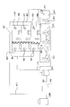
- FIG. 1 is a refrigerant circuit diagram illustrating an example of a refrigerant circuit configuration of a hot water supply and air conditioning composite apparatus 100 according to an embodiment of the present invention. Based on FIG. 1, the refrigerant circuit configuration and operation of the hot water supply air-conditioning composite apparatus 100 will be described.
- the hot water supply / air conditioning complex apparatus 100 is installed in, for example, a sports gym, a hotel, a welfare facility, and the like, and can simultaneously supply a cooling load, a heating load, and a hot water supply load by using a refrigeration cycle (heat pump cycle) that circulates refrigerant. is there.
- a refrigeration cycle heat pump cycle
- the hot water supply / air conditioning complex apparatus 100 includes at least an air conditioning refrigeration cycle 1, a hot water supply refrigeration cycle 2, and a hot water supply load 3.
- the refrigeration cycle 1 for air conditioning and the refrigeration cycle 2 for hot water supply are refrigerant-refrigerant heat exchangers 41, and the refrigeration cycle for hot water supply 2 and the hot water supply load 3 are heat medium-refrigerant heat exchangers 51. The heat exchange is performed without mixing.
- the air-conditioning refrigeration cycle 1 includes a heat source unit A, a plurality of indoor units B in charge of, for example, a cooling load or a heating load, and a hot water supply heat source circuit C serving as a heat source for the hot water supply refrigeration cycle 2.
- the indoor unit B and the hot water supply heat source circuit C are connected to the heat source unit A in parallel.
- the function of the indoor unit B and the hot water supply heat source circuit C is exhibited by switching and circulating the flow of the air conditioning refrigerant as the first refrigerant in the heat source unit A, the indoor unit B, and the hot water supply heat source circuit C. It is supposed to let you.
- the heat source unit A has a function of supplying hot or cold heat to the indoor unit B and the hot water supply heat source circuit C.
- an air-conditioning compressor 101 a four-way valve 102 which is a flow path switching means, a heat source machine side heat exchanger 103, and an accumulator 104 are mounted in series.
- the heat source unit A may be provided with a blower such as a fan for supplying air to the heat source unit side heat exchanger 103 in the vicinity of the heat source unit side heat exchanger 103.
- the air-conditioning compressor 101 sucks air-conditioning refrigerant and compresses the air-conditioning refrigerant to a high temperature and high pressure state.
- the four-way valve 102 switches the flow of the air conditioning refrigerant.
- the heat source apparatus side heat exchanger 103 functions as an evaporator or a radiator (condenser), performs heat exchange between air supplied from a blower (not shown) and the air conditioning refrigerant, and converts the air conditioning refrigerant into an evaporating gas. Or is condensed or liquefied.
- the accumulator 104 is disposed on the suction side of the air conditioning compressor 101, and stores excess air conditioning refrigerant.
- the accumulator 104 may be any container that can store excess air-conditioning refrigerant.
- the indoor unit B has a function of receiving heating or cooling supply from the heat source unit A and taking charge of heating load or cooling load.
- an air conditioning throttle means 117 and a use side heat exchanger 118 are mounted connected in series.
- the indoor unit B shows an example in which two air conditioning throttle means 117 and two use side heat exchangers 118 are mounted in parallel.
- the indoor unit B may be provided with a blower such as a fan for supplying air to the use side heat exchanger 118 in the vicinity of the use side heat exchanger 118.
- the air conditioning throttle means 117 has a function as a pressure reducing valve or an expansion valve, and expands the air conditioning refrigerant by reducing the pressure.
- the air-conditioning throttle means 117 may be constituted by a controllable opening degree, for example, a precise flow rate control means using an electronic expansion valve, an inexpensive refrigerant flow rate control means such as a capillary tube, or the like.
- the use-side heat exchanger 118 functions as a radiator (condenser) or an evaporator, performs heat exchange between air supplied from a blower (not shown) and the air conditioning refrigerant, and condenses or liquefies the air conditioning refrigerant. Evaporative gasification.
- the air conditioning throttle means 117 and the use side heat exchanger 118 are connected in series.
- the hot water supply heat source circuit C has a function of supplying the hot or cold heat from the heat source device A to the hot water supply refrigeration cycle 2 via the refrigerant-refrigerant heat exchanger 41.
- a hot water supply heat source throttle means 119 and a refrigerant-refrigerant heat exchanger 41 are connected in series. That is, the air-conditioning refrigeration cycle 1 and the hot water supply refrigeration cycle 2 are cascade-connected by the refrigerant-refrigerant heat exchanger 41.
- the hot water supply heat source throttling means 119 has a function as a pressure reducing valve or an expansion valve like the air conditioning throttling means 117, and decompresses and expands the air conditioning refrigerant.
- the hot water supply heat source throttling means 119 is preferably constituted by a controllable opening degree, such as a precise flow rate control means using an electronic expansion valve, an inexpensive refrigerant flow rate control means such as a capillary.
- the refrigerant-refrigerant heat exchanger 41 functions as a radiator (condenser) or an evaporator, and serves as a hot water supply refrigerant that is a second refrigerant that circulates in the hot water supply refrigeration cycle 2 and for air conditioning that circulates in the air conditioning refrigeration cycle 1. Heat exchange is performed with the refrigerant.
- the air-conditioning refrigeration cycle 1 includes the air-conditioning compressor 101, the four-way valve 102, the use-side heat exchanger 118, the air-conditioning throttle means 117, and the heat-source-unit-side heat exchanger 103, the air-conditioning compressor 101,
- the four-way valve 102, the refrigerant-refrigerant heat exchanger 41, the hot water supply heat source throttling means 119, and the heat source machine side heat exchanger 103 are connected in series, and the use side heat exchanger 118 and the refrigerant-refrigerant heat exchanger 41 are connected.
- the four-way valve 102 is connected to the use side heat exchanger 118 and the refrigerant-refrigerant heat exchanger 41 through a gas side connection pipe 106.
- the heat source machine side heat exchanger 103, the air conditioning throttle means 117 and the hot water supply heat source throttle means 119 are connected by a liquid side connection pipe 107.
- the air-conditioning compressor 101 is not particularly limited as long as it can compress the sucked refrigerant into a high pressure state.
- the air-conditioning compressor 101 can be configured using various types such as reciprocating, rotary, scroll, or screw.
- the air-conditioning compressor 101 may be configured as a type in which the rotational speed can be variably controlled by an inverter, or may be configured as a type in which the rotational speed is fixed.
- the type of refrigerant circulating in the air-conditioning refrigeration cycle 1 is not particularly limited.
- natural refrigerants such as carbon dioxide (CO 2 ), hydrocarbons, and helium, and alternatives that do not contain chlorine such as HFC410A, HFC407C, and HFC404A
- Either a refrigerant or a fluorocarbon refrigerant such as R22 or R134a used in existing products may be used.
- the operation of the air-conditioning refrigeration cycle 1 will be described.
- the operation in the case where the indoor unit B is in charge of the heating load and the hot water supply heat source circuit C is in charge of the hot water supply load will be described.
- the air-conditioning refrigerant heated to high temperature and high pressure by the air-conditioning compressor 101 is discharged from the air-conditioning compressor 101, led to the gas side connection pipe 106 via the four-way valve 102, and air-conditioning in a superheated gas state.
- the refrigerant flows into the indoor unit B and the hot water supply heat source circuit C as the refrigerant for use.
- the air-conditioning refrigerant that has flowed into the indoor unit B dissipates heat in the use-side heat exchanger 118 (that is, warms the room air), is depressurized by the air-conditioning throttle means 117, flows out of the indoor unit B, and joins.
- the air conditioning refrigerant that has flowed into the hot water supply heat source circuit C radiates heat in the refrigerant-refrigerant heat exchanger 41 (that is, heat is supplied to the hot water supply refrigeration cycle 2), and is depressurized by the hot water supply heat source throttle means 119.
- the refrigerant flows out of the heat source circuit C and merges with the air conditioning refrigerant that flows out of the indoor unit B.
- the combined air-conditioning refrigerant is guided to the heat source unit-side heat exchanger 103, and depending on the operating conditions, the remaining liquid refrigerant is evaporated, and returns to the air-conditioning compressor 101 via the four-way valve 102 and the accumulator 104.
- the hot water supply refrigeration cycle 2 includes a hot water supply compressor 21, a heat medium-refrigerant heat exchanger 51, a hot water supply throttle means 22, and a refrigerant-refrigerant heat exchanger 41. That is, the hot water supply refrigeration cycle 2 includes a hot water supply compressor 21, a heat medium-refrigerant heat exchanger 51, a hot water supply throttle means 22, and a refrigerant-refrigerant heat exchanger 41 connected in series by the refrigerant pipe 45. This is established by constituting a two refrigerant circuit and circulating a hot water supply refrigerant in the second refrigerant circuit.
- the hot water supply compressor 21 sucks in the hot water supply refrigerant and compresses the hot water supply refrigerant to a high temperature and high pressure state.
- the hot water supply compressor 21 may be configured as a type in which the rotation speed can be variably controlled by an inverter, or may be configured as a type in which the rotation speed is fixed.
- the hot water supply compressor 21 is not particularly limited as long as it can compress the sucked hot water supply refrigerant into a high pressure state.
- the hot water supply compressor 21 can be configured using various types such as reciprocating, rotary, scroll, or screw.
- the heat medium-refrigerant heat exchanger 51 exchanges heat between a heat medium (fluid such as water or antifreeze) that circulates in the hot water supply load 3 and a hot water refrigerant that circulates in the hot water refrigeration cycle 2. It is. That is, the hot water supply refrigeration cycle 2 and the hot water supply load 3 are cascade-connected via the heat medium-refrigerant heat exchanger 51.
- the hot water supply throttle means 22 has a function as a pressure reducing valve or an expansion valve, and expands the hot water supply refrigerant by reducing the pressure.
- the hot water supply throttling means 22 may be constituted by a controllable opening degree, such as a precise flow rate control means using an electronic expansion valve, an inexpensive refrigerant flow rate control means such as a capillary.
- the refrigerant-refrigerant heat exchanger 41 performs heat exchange between the hot water supply refrigerant circulating in the hot water supply refrigeration cycle 2 and the air conditioning refrigerant circulating in the air conditioning refrigeration cycle 1.
- the type of the hot water supply refrigerant circulating in the hot water supply refrigeration cycle 2 is not particularly limited.
- natural refrigerants such as carbon dioxide, hydrocarbons, and helium
- alternative refrigerants not containing chlorine such as HFC410A, HFC407C, and HFC404A
- any of CFC-based refrigerants such as R22 and R134a used in existing products may be used.
- the hot water supply refrigerant that has been heated to a high temperature and high pressure by the hot water supply compressor 21 is discharged from the hot water supply compressor 21 and flows into the heat medium-refrigerant heat exchanger 51.
- the water flowing through the hot water supply load 3 is heated by the heat supply of the hot water supply refrigerant radiating heat.
- the hot water supply refrigerant is expanded by the hot water supply throttling means 22 to a temperature equal to or lower than the outlet temperature of the refrigerant-refrigerant heat exchanger 41 in the hot water supply heat source circuit C of the air conditioning refrigeration cycle 1.
- the expanded hot water supply refrigerant receives and evaporates from the air conditioning refrigerant flowing through the hot water supply heat source circuit C constituting the air conditioning refrigeration cycle 1 in the refrigerant-refrigerant heat exchanger 41, and returns to the hot water supply compressor 21.
- the hot water supply load 3 includes a water circulation pump 31, a heat medium-refrigerant heat exchanger 51, and a hot water storage tank 32. That is, in the hot water supply load 3, the water circulation pump 31, the heat medium-refrigerant heat exchanger 51, and the hot water storage tank 32 are connected in series by the hot water storage water circulation pipe 203 to form a water circuit (heat medium circuit). This is achieved by circulating hot water supply water in this water circuit.
- the hot water circulation pipe 203 constituting the water circuit is constituted by a copper pipe, a stainless pipe, a steel pipe, a vinyl chloride pipe, or the like.
- the water circulation pump 31 sucks the water stored in the hot water storage tank 32, pressurizes the water, and circulates the inside of the hot water supply load 3.
- the water circulation pump 31 is of a type whose rotational speed is controlled by an inverter. Configure.
- the heat medium-refrigerant heat exchanger 51 is between the heat medium (fluid such as water or antifreeze) that circulates through the hot water supply load 3 and the hot water refrigerant that circulates through the hot water refrigeration cycle 2. Heat exchange is performed.
- the hot water storage tank 32 stores water heated by the heat medium-refrigerant heat exchanger 51.
- the relatively low temperature water stored in the hot water storage tank 32 is drawn from the bottom of the hot water storage tank 32 and pressurized by the water circulation pump 31.
- the water pressurized by the water circulation pump 31 flows into the heat medium-refrigerant heat exchanger 51, and receives heat from the hot water supply refrigerant circulating in the hot water supply refrigeration cycle 2 by the heat medium-refrigerant heat exchanger 51. . That is, the water flowing into the heat medium-refrigerant heat exchanger 51 is boiled by the hot water supply refrigerant circulating in the hot water supply refrigeration cycle 2, and the temperature rises. Then, the boiled water returns to the relatively hot upper portion of the hot water storage tank 32 and is stored in the hot water storage tank 32.
- the refrigerant-refrigerant heat exchanger 41, the hot water supply heat source throttle means 119, the heat medium-refrigerant heat exchanger 51, the hot water supply compressor 21, and the hot water supply throttle means 22 are referred to as a hot water heater.
- the hot water supply and air conditioning complex apparatus 100 includes a sensor for detecting the discharge pressure of the air conditioning refrigerant, a sensor for detecting the suction pressure of the air conditioning refrigerant, a sensor for detecting the discharge temperature of the air conditioning refrigerant, and air conditioning.
- a sensor for detecting the suction temperature of the refrigerant a sensor for detecting the temperature of the air-conditioning refrigerant flowing into and out of the heat source unit side heat exchanger 103, a sensor for detecting the outside air temperature taken into the heat source unit A, and the use side heat exchanger 118 A sensor for detecting the temperature of the air-conditioning refrigerant flowing in and out, a sensor for detecting the temperature of water stored in the hot water storage tank 32, and the like may be provided.
- control means that controls the operation of the hot water supply air-conditioning composite apparatus 100, and the drive frequency of the air-conditioning compressor 101 and the four-way valve It is used for control of switching of 102, driving frequency of the hot water supply compressor 21, driving of the water circulation pump 31, opening of each throttle means, and the like.
- the air conditioning refrigeration cycle 1 and the hot water supply refrigeration cycle 2 are independent refrigerant circuit configurations (the first refrigerant circuit constituting the air conditioning refrigeration cycle 1 and the hot water supply refrigeration cycle 2 constituting the first refrigerant circuit 1).
- the refrigerant circulating through each refrigerant circuit may be the same type or different types. That is, the refrigerant in each refrigerant circuit flows so as to exchange heat with each other in the refrigerant-refrigerant heat exchanger 41 and the heat medium-refrigerant heat exchanger 51 without being mixed.
- a refrigerant having a low critical temperature when used as the hot water supply refrigerant, it is assumed that the hot water supply refrigerant in the heat dissipation process in the heat medium-refrigerant heat exchanger 51 enters a supercritical state when hot water supply is performed. .
- the COP fluctuates greatly due to changes in the radiator pressure and the outlet temperature of the radiator, and more advanced control is required in order to obtain a high COP.
- a refrigerant having a low critical temperature has a high saturation pressure for the same temperature, and accordingly, it is necessary to increase the thickness of the piping and the compressor.
- the target temperature for hot water supply is often 62 ° C. or higher at a minimum. Is done.
- a refrigerant having a critical temperature of 62 ° C. or higher is adopted as the hot water supply refrigerant. This is because, if such a refrigerant is employed as the hot water supply refrigerant of the hot water supply refrigeration cycle 2, a high COP can be obtained more stably at a lower cost.
- coolant was stored by the liquid receiver (accumulator 104) in the refrigerating cycle 1 for an air conditioning was shown, it is not restricted to this, It is stored with the heat exchanger used as a heat radiator in a refrigerating cycle. In this case, the accumulator 104 may be removed.
- FIG. 1 the case where two or more indoor units B are connected is shown as an example, but the number of connected units is not particularly limited. For example, one or more indoor units B may be connected. . And the capacity
- the hot water supply load system is configured in a two-way cycle. Therefore, when hot water supply demand (for example, 80 ° C.) is provided, What is necessary is just to make the temperature of the radiator of the refrigeration cycle 2 high (for example, condensing temperature 85 ° C.), and when there is another heating load, without increasing the condensing temperature of the indoor unit B (for example 50 ° C.). It will save energy.
- the hot water supply air conditioning complex device 100 collects the heat that has been discharged into the atmosphere in the past. Since hot water is reused, the system COP is greatly improved and energy is saved.
- the load of the indoor unit B and the load of the hot water heater can be switched by a flow path switching device such as a flow path switching valve. If it does in this way, it will be possible to appropriately switch between the daytime air conditioning load in the indoor unit B and the nighttime cooling load in the water heater, or the daytime air conditioning load in the indoor unit B and the heating load in the water heater. Leveling can be realized, the extra equipment cost can be omitted, and the running cost can be reduced. In other words, by making it possible to switch between the air conditioning load and the hot water supply load, it is possible to effectively use nighttime power.
- FIG. 2 is a graph showing the relationship between the heat exchanger capacity of the heat source device side heat exchanger 103 and the heating operation capacity ratio / outdoor load. Based on FIG. 2, the heat-source-unit-side heat exchanger 103 that enables heating operation throughout the year will be described.
- the vertical axis represents the heat exchanger capacity (outdoor AK) of the heat source device side heat exchanger 103
- the horizontal axis represents the heating operation capacity ratio (indoor load + hot water supply load) / outdoor load.
- the hot water supply / air-conditioning composite apparatus 100 When using the hot water supply / air-conditioning composite apparatus 100 only for normal air conditioning applications, it is common to perform heating operation at an outdoor air wet bulb temperature of 15 ° C. or lower. On the other hand, when the hot water supply operation is performed using the hot water supply air-conditioning composite apparatus 100 under the condition where the outdoor wet bulb temperature exceeds 15 ° C. in summer or the like, it is necessary to perform the hot water supply operation regardless of the outdoor air temperature. Further, when a hot water supply / air-conditioning combined apparatus that can be switched between cooling operation and heating operation is used under conditions where the outdoor wet bulb temperature exceeds 15 ° C., such as in summer, the evaporation capability becomes excessive with respect to the condensation capability. Therefore, high pressure rise is likely to occur and high temperature hot water cannot be discharged.
- the hot water supply air-conditioning composite apparatus 100 when the outdoor wet bulb temperature rises to 32 ° C., the operating range of the air conditioning compressor 101 is reduced by reducing the heat exchanger capacity (outdoor AK) of the heat source apparatus side heat exchanger 103.
- the high pressure rise is suppressed while not deviating from the above.
- the capacity of the heat source unit side heat exchanger 103 is controlled during heating operation to load the heat source unit A, the plurality of indoor units B, and the hot water supply. It balances with the total load of the machine and makes it possible to supply a stable heat source even when the outside air temperature is high, such as in summer.
- the controller for driving the air-conditioning compressor 101 in the heat source device A needs to have a predetermined airflow or more in order to dissipate a predetermined amount of heat input to the air-conditioning compressor 101.
- the heat exchanger capacity (outdoor AK) of the heat source device A has a lower limit (minimum AK), and the heat exchanger capacity (outdoor AK) cannot be further reduced. From this minimum AK, operation is continued in a range where the heat exchanger capacity (outdoor AK) and the heating operation capacity ratio ((indoor load + hot water supply load) / outdoor load) of the heat source device side heat exchanger 103 are in an equilibrium state (solid line). With this solid line as a boundary, the high pressure rises in the upper left range, and the high pressure rises in the lower right range. In particular, when the outside air temperature is high, such as 32 ° C., the temperature becomes close to the minimum AK.
- the capacity control of the heat source device side heat exchanger 103 is performed by adjusting the amount of refrigerant flowing through the heat transfer tubes constituting the heat exchanger, or adjusting the amount of air supplied to the heat exchanger, for example. Just do it. Further, when only the water heater is in operation, the capacity of the heat source unit side heat exchanger 103 may be controlled so that the high pressure of the refrigerant discharged from the air conditioning compressor 101 falls within a predetermined range.
- the hot water supply air-conditioning combined apparatus 100 having the above configuration, when the capacity of the heat source unit side heat exchanger 103 is controlled, the air conditioning load and the hot water supply load are balanced, and the outside air temperature is high as in summer. However, stable heating operation can be realized.
- air conditioning load and hot water supply load air conditioning in studios and general offices is performed in the daytime, pool water is cooled in the summer, and heat is heated in the winter and air conditioning equipment and hot water supply in the winter. Since the devices are used in common, not only the initial cost is reduced, but also the power is leveled by the effective use of nighttime power, resulting in energy saving.
- the hot water supply and air-conditioning combined apparatus 100 not only a stable high-temperature hot water supply is possible even when the outside air temperature is high, but a special configuration for that purpose is unnecessary, and the cost can be reduced accordingly.
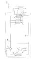
- FIG. 3 is a schematic diagram showing an installation example of the hot water supply air-conditioning composite apparatus 100. Based on FIG. 3, the operation method based on installation of the hot water supply air-conditioning composite apparatus 100 will be described in detail.
- the hot water supply and air-conditioning composite apparatus 100 is illustrated in an image of a state where it is installed in a building 500 such as a sports gym, hotel, or welfare facility.
- the building 500 includes a residential space 408 provided with a hot water supply room 406 and a commercial facility 410 provided with a cooking area 411.
- the hot water supply and air conditioning complex apparatus 100 is configured by connecting an outdoor unit 400, a hot water supply apparatus 401, and five indoor air conditioners 407 through refrigerant pipes 412 (corresponding to the gas side connection pipe 106 and the liquid side connection pipe 107). Yes.
- the outdoor unit 400 corresponds to the heat source unit A shown in FIG.
- the water heater 401 corresponds to the water heater shown in FIG.
- the indoor air conditioner 407 corresponds to the indoor unit B shown in FIG.
- a hot water storage tank 403 corresponding to the hot water storage tank 32 is connected via a hot water storage water circulation pipe 203.
- the hot water storage tank 403 is connected to the hot water supply hot water outlet 405 of the hot water supply use room 406 via the supply main pipe 415, and connected to the hot water supply hot water outlet 405 of the kitchen 411 via the supply pipe 414.
- a year-round operation method of the hot water supply / air conditioning composite apparatus 100 will be described.
- ⁇ Operation Method of Hot Water Supply Air Conditioning Combined Device 100 in Summer the outdoor unit 400 often performs a heating operation, and the indoor air conditioner 407 often performs a cooling operation.
- hot water is often used in the hot water supply room 406 installed in the living space 408 regardless of the time. That is, in the hot water supply use room 406, a person often uses hot water depending on purposes such as showering or bathing.
- the kitchen 411 is often used for hot water supply and cooling throughout the year.
- the outdoor temperature is usually high in summer. Therefore, in the hot water supply and air conditioning composite apparatus 100, the set temperature is set low, and the amount of hot water stored in the hot water storage tank 403 is increased. Further, in the hot water supply air-conditioning composite apparatus 100, the heat that has been discarded in the outdoor unit 400 as waste heat in the past is used in the hot water boiling operation by the hot water supply apparatus 401, thereby enabling an energy saving operation.
- the temperature range used for hot water supply may be low, the set temperature can be lowered, the time for operating the hot water supply device 401 is short, the operating time can be reduced as a system, and the energy is saved. Driving is possible.
- an energy saving operation in the system can be performed by performing a heating operation with the hot water supply device 401 and exhausting heat to the living space 408.
- the outdoor unit 400 often performs a cooling operation
- the indoor air conditioner 407 often performs a heating operation.
- hot water is often used in the hot water supply room 406 installed in the living space 408 regardless of the time.
- the supply pipe 414 and the supply main pipe 415 are required to perform a pipe freezing protection operation due to a decrease in the outside air temperature.
- the kitchen 411 is required for hot water supply and cooling.
- the freeze protection operation has been performed by winding an electric heater or the like around the water pipe.
- it is preferable to prevent the pipe from being frozen by supplying medium temperature water stored in the hot water storage tank 403 at night or when the outside air temperature is lowered.
- the capacity of the heat source unit side heat exchanger 103 is controlled during the heating operation to balance the load of the heat source unit A and the total load of the indoor unit B and the hot water supply unit. Therefore, even when the outside air temperature is high particularly in summer, stable hot high-temperature hot water can be obtained, and operation with optimum energy efficiency throughout the year can be realized.
- FIG. FIG. 4 is a refrigerant circuit diagram illustrating an example of a refrigerant circuit configuration of a hot water supply and air conditioning composite apparatus 100A according to Embodiment 2 of the present invention. Based on FIG. 4, hot water supply air-conditioning composite apparatus 100A will be described.
- this hot water supply / air conditioning complex apparatus 100A is installed in, for example, a sports gym, a hotel, a welfare facility, etc., similarly to the hot water supply / air conditioning complex apparatus 100 according to the first embodiment.
- the cooling load, the heating load, and the hot water supply load can be simultaneously supplied by using a refrigeration cycle (heat pump cycle) for circulating the refrigerant.
- a refrigeration cycle heat pump cycle
- the hot water supply air-conditioning composite apparatus 100A is not provided with the hot water supply refrigeration cycle 2. That is, the hot water supply / air conditioning complex apparatus 100A connects the air conditioning refrigeration cycle and the hot water supply load 3 via the heat medium-refrigerant heat exchanger 51. Needless to say, the hot water supply and air conditioning complex apparatus 100A may be installed in the mode shown in FIG. In addition, at least a part of the heat medium-refrigerant heat exchanger 51 is mounted on the water heater.
- the hot water supply / air conditioning complex apparatus 100A having the above-described configuration, as with the hot water supply / air conditioning complex apparatus 100 according to Embodiment 1, by controlling the capacity of the heat source unit side heat exchanger 103, the air conditioning load and the hot water supply load are controlled. Even when the outside air temperature is high, such as in summer, stable heating operation can be realized. In addition, by switching between air conditioning load and hot water supply load, air conditioning in studios and general offices is performed in the daytime, pool water is cooled in the summer, and heat is heated in the winter and air conditioning equipment and hot water supply in the winter. Since the devices are used in common, not only the initial cost is reduced, but also the power is leveled by the effective use of nighttime power, resulting in energy saving. In addition, according to the hot-water supply / air-conditioning combined apparatus 100A, not only stable high-temperature hot water supply is possible even when the outside air temperature is high, but a special configuration for that purpose is not required, and the cost can be reduced accordingly.
- the load of the indoor unit B and the load of the hot water heater can be switched. If it does in this way, it will be possible to appropriately switch between the daytime air conditioning load in the indoor unit B and the nighttime cooling load in the water heater, or the daytime air conditioning load in the indoor unit B and the heating load in the water heater. Leveling can be realized, the extra equipment cost can be omitted, and the running cost can be reduced. In other words, by making it possible to switch between the air conditioning load and the hot water supply load, it is possible to effectively use nighttime power.
- FIG. 5 is a refrigerant circuit diagram illustrating an example of a refrigerant circuit configuration of a hot water supply air-conditioning composite apparatus 100B according to Embodiment 3 of the present invention. Based on FIG. 5, the hot water supply air-conditioning composite apparatus 100B will be described.
- This hot water supply air-conditioning composite apparatus 100B is installed in, for example, a sports gym, a hotel, a welfare facility, etc., and uses a refrigeration cycle (heat pump cycle) that circulates refrigerant, as with hot water supply air conditioning composite apparatus 100 according to Embodiment 1.
- the cooling load, the heating load and the hot water supply load can be supplied simultaneously.
- the hot water supply air-conditioning composite apparatus 100B differs from the hot water supply air conditioning composite apparatus according to the first or second embodiment in that a bypass pipe 10 that bypasses the heat source unit side heat exchanger 103 is provided as shown in FIG. Yes.
- the bypass pipe 10 is provided so as to connect the entrance / exit side of the heat source apparatus side heat exchanger 103.
- the bypass pipe 10 is provided with a bypass valve 11 that opens and closes the bypass pipe 10. That is, by controlling the opening and closing of the bypass valve 11, a part of the refrigerant flowing into the heat source unit side heat exchanger 103 is caused to flow into the bypass pipe 10, and the capacity of the heat source unit side heat exchanger 103 is controlled. is there.
- the hot water supply / air conditioning composite apparatus 100B may be installed in the mode shown in FIG.
- the hot water supply / air conditioning composite apparatus 100B having the above-described configuration, as with the hot water supply / air conditioning composite apparatus 100 according to Embodiment 1, by controlling the capacity of the heat source unit side heat exchanger 103, the air conditioning load and the hot water supply load are controlled. Even when the outside air temperature is high, such as in summer, stable heating operation can be realized. In addition, by switching between air conditioning load and hot water supply load, air conditioning in studios and general offices is performed in the daytime, pool water is cooled in the summer, and heat is heated in the winter and air conditioning equipment and hot water supply in the winter. Since the devices are used in common, not only the initial cost is reduced, but also the power is leveled by the effective use of nighttime power, resulting in energy saving. In addition, according to the hot water supply and air-conditioning combined apparatus 100B, not only a stable high-temperature hot water supply is possible even when the outside air temperature is high, but a special configuration for that purpose is unnecessary, and the cost can be reduced accordingly.
- the load of the indoor unit B and the load of the hot water heater can be switched by a flow path switching device such as a flow path switching valve. If it does in this way, it will be possible to appropriately switch between the daytime air conditioning load in the indoor unit B and the nighttime cooling load in the water heater, or the daytime air conditioning load in the indoor unit B and the heating load in the water heater. Leveling can be realized, the extra equipment cost can be omitted, and the running cost can be reduced. In other words, by making it possible to switch between the air conditioning load and the hot water supply load, it is possible to effectively use nighttime power.
Landscapes
- Engineering & Computer Science (AREA)
- Mechanical Engineering (AREA)
- General Engineering & Computer Science (AREA)
- Physics & Mathematics (AREA)
- Thermal Sciences (AREA)
- Chemical & Material Sciences (AREA)
- Combustion & Propulsion (AREA)
- Life Sciences & Earth Sciences (AREA)
- Sustainable Development (AREA)
- Heat-Pump Type And Storage Water Heaters (AREA)
- Air Conditioning Control Device (AREA)
- Other Air-Conditioning Systems (AREA)
Abstract
Description
図1は、本発明の実施の形態に係る給湯空調複合装置100の冷媒回路構成の一例を示す冷媒回路図である。図1に基づいて、給湯空調複合装置100の冷媒回路構成及び動作について説明する。この給湯空調複合装置100は、たとえばスポーツジムやホテル、福祉施設等に設置され、冷媒を循環させる冷凍サイクル(ヒートポンプサイクル)を利用することで冷房負荷、暖房負荷及び給湯負荷を同時に供給できるものである。
空調用冷凍サイクル1は、熱源機Aと、たとえば冷房負荷もしくは暖房負荷を担当する複数の室内機Bと、給湯用冷凍サイクル2の熱源となる給湯熱源用回路Cと、によって構成されている。このうち、室内機B及び給湯熱源用回路Cは、熱源機Aに対して並列となるように接続されている。そして、熱源機Aと、室内機B及び給湯熱源用回路Cと、において第1冷媒である空調用冷媒の流れを切り換え循環させることで、室内機B及び給湯熱源用回路Cとしての機能を発揮させるようになっている。
熱源機Aは、室内機B及び給湯熱源用回路Cに温熱又は冷熱を供給する機能を有している。この熱源機Aには、空調用圧縮機101と、流路切替手段である四方弁102と、熱源機側熱交換器103と、アキュムレーター104とが直列に接続されて搭載されている。なお、熱源機Aには、熱源機側熱交換器103に空気を供給するためのファン等の送風機を熱源機側熱交換器103の近傍位置に設けるとよい。
室内機Bは、熱源機Aからの温熱又は冷熱の供給を受けて暖房負荷又は冷房負荷を担当する機能を有している。室内機Bには、空調用絞り手段117と、利用側熱交換器118とが、直列に接続されて搭載されている。なお、室内機Bには、2台の空調用絞り手段117と、2台の利用側熱交換器118とが、それぞれ並列に搭載されている場合を例に示している。また、室内機Bには、利用側熱交換器118に空気を供給するためのファン等の送風機を利用側熱交換器118の近傍に設けるとよい。
給湯熱源用回路Cは、熱源機Aからの温熱又は冷熱を冷媒-冷媒熱交換器41を介して給湯用冷凍サイクル2に供給する機能を有している。給湯熱源用回路Cには、給湯熱源用絞り手段119と、冷媒-冷媒熱交換器41とが、直列に接続されて構成されている。つまり、空調用冷凍サイクル1と給湯用冷凍サイクル2とは、冷媒-冷媒熱交換器41でカスケード接続されているのである。
ここでは、室内機Bが暖房負荷を担当し、給湯熱源用回路Cが給湯負荷を担当する場合における運転動作について説明する。
給湯用冷凍サイクル2は、給湯用圧縮機21と、熱媒体-冷媒熱交換器51と、給湯用絞り手段22と、冷媒-冷媒熱交換器41と、によって構成されている。つまり、給湯用冷凍サイクル2は、給湯用圧縮機21、熱媒体-冷媒熱交換器51、給湯用絞り手段22、及び、冷媒-冷媒熱交換器41が冷媒配管45で直列に接続されて第2冷媒回路を構成し、この第2冷媒回路に給湯用冷媒を循環させることで成立している。
まず、給湯用圧縮機21で高温・高圧にされた給湯用冷媒は、給湯用圧縮機21から吐出して、熱媒体-冷媒熱交換器51に流入する。この熱媒体-冷媒熱交換器51では、流入した給湯用冷媒が放熱することで給湯用負荷3を循環している水を加熱する。この給湯用冷媒は、給湯用絞り手段22で空調用冷凍サイクル1の給湯熱源用回路Cにおける冷媒-冷媒熱交換器41の出口温度以下まで膨張される。膨張された給湯用冷媒は、冷媒-冷媒熱交換器41で、空調用冷凍サイクル1を構成する給湯熱源用回路Cを流れる空調用冷媒から受熱して蒸発し、給湯用圧縮機21へ戻る。
給湯用負荷3は、水循環用ポンプ31と、熱媒体-冷媒熱交換器51と、貯湯タンク32と、によって構成されている。つまり、給湯用負荷3は、水循環用ポンプ31、熱媒体-冷媒熱交換器51、及び、貯湯タンク32が貯湯水循環用配管203で直列に接続されて水回路(熱媒体回路)を構成し、この水回路に給湯用水を循環させることで成立している。なお、水回路を構成する貯湯水循環用配管203は、銅管やステンレス管、鋼管、塩化ビニル系配管などによって構成されている。
まず、貯湯タンク32に蓄えられている比較的低温な水は、水循環用ポンプ31によって貯湯タンク32の底部から引き出されるとともに加圧される。水循環用ポンプ31で加圧された水は、熱媒体-冷媒熱交換器51に流入し、この熱媒体-冷媒熱交換器51で給湯用冷凍サイクル2を循環している給湯用冷媒から受熱する。すなわち、熱媒体-冷媒熱交換器51に流入した水は、給湯用冷凍サイクル2を循環している給湯用冷媒によって沸き上げられて、温度が上昇するのである。そして、沸き上げられた水は、貯湯タンク32の比較的高温な上部へ戻り、この貯湯タンク32に蓄えられることになる。
<夏期の場合における給湯空調複合装置100の運転方法>
この場合、室外機400は暖房運転、室内空調機407は冷房運転を行なっていることが多い。また、居住空間408に設置されている給湯用利用室406では、時間に関係なく、湯が利用されることが多い。つまり、給湯用利用室406では、人がシャワーや入浴といった用途によって湯を使用することが多い。さらに、調理場411では、年間を通して給湯用途及び冷房用途が使用されていることが多い。
この場合、室外機400は冷房運転、室内空調機407は暖房運転を行なっていることが多い。また、居住空間408に設置されている給湯用利用室406では、時間に関係なく、湯が利用されることが多い。さらに、夜間や早朝には、供給配管414、及び、供給主配管415は、外気温度の低下による配管凍結保護運転が要求される。また年間を通して、調理場411は給湯用途、冷房用途が必要となる。
図4は、本発明の実施の形態2に係る給湯空調複合装置100Aの冷媒回路構成の一例を示す冷媒回路図である。図4に基づいて、給湯空調複合装置100Aについて説明する。中温の給湯需要(たとえば45℃)を提供する場合に、この給湯空調複合装置100Aは、実施の形態1に係る給湯空調複合装置100と同様に、たとえばスポーツジムやホテル、福祉施設等に設置され、冷媒を循環させる冷凍サイクル(ヒートポンプサイクル)を利用することで冷房負荷、暖房負荷及び給湯負荷を同時に供給できるものである。
図5は、本発明の実施の形態3に係る給湯空調複合装置100Bの冷媒回路構成の一例を示す冷媒回路図である。図5に基づいて、給湯空調複合装置100Bについて説明する。この給湯空調複合装置100Bは、実施の形態1に係る給湯空調複合装置100と同様に、たとえばスポーツジムやホテル、福祉施設等に設置され、冷媒を循環させる冷凍サイクル(ヒートポンプサイクル)を利用することで冷房負荷、暖房負荷及び給湯負荷を同時に供給できるものである。
Claims (5)
- 第1冷媒を圧縮する空調用圧縮機及び熱源機側熱交換器が搭載された少なくとも1台の熱源機と、
前記熱源機に対して並列に接続され、前記第1冷媒が流れる利用側熱交換器が搭載された複数台の室内機と、
前記熱源機に対して並列に接続され、前記第1冷媒と前記第2冷媒とが流れる冷媒-冷媒熱交換器、熱媒体と前記第2冷媒が流れる熱媒体-冷媒熱交換器、及び、前記第2冷媒を圧縮する給湯用圧縮機が搭載された少なくとも1台の給湯機と、を備え、
暖房運転時において、
前記熱源機に搭載されている前記熱源機側熱交換機の容量を制御して、
前記熱源機の負荷と、前記室内機及び前記給湯機の合計負荷と、の均衡を図るようにしている
給湯空調複合装置。 - 第1冷媒を圧縮する空調用圧縮機及び熱源機側熱交換器が搭載された少なくとも1台の熱源機と、
前記熱源機に対して並列に接続され、前記第1冷媒が流れる利用側熱交換器が搭載された複数台の室内機と、
前記熱源機に対して並列に接続され、熱媒体と前記第1冷媒が流れる熱媒体-冷媒熱交換器が少なくとも搭載された少なくとも1台の給湯機と、を備え、
暖房運転時において、
前記熱源機に搭載されている前記熱源機側熱交換機の容量を制御して、
前記熱源機の負荷と、前記室内機及び前記給湯機の合計負荷と、の均衡を図るようにしている
給湯空調複合装置。 - 前記熱源機側熱交換器をバイパスするバイパス管と、
前記バイパス管に設置されたバイパス弁と、を設け、
前記バイパス弁を制御することで前記バイパス管に流入する前記第1冷媒の流量を調整することで前記熱源機に搭載されている前記熱源機側熱交換器の容量を制御する
請求項1又は2に記載の給湯空調複合装置。 - 前記室内機の負荷と前記給湯機の負荷とを切り替え可能に構成している
請求項1~3のいずれか一項に記載の給湯空調複合装置。 - 前記給湯機のみが運転している状態において、前記空調用圧縮機から吐出される前記第1冷媒の高圧圧力を所定範囲内とするようにして前記熱源機に搭載されている前記熱源機側熱交換器の容量を制御する
請求項1~4のいずれか一項に記載の給湯空調複合装置。
Priority Applications (5)
| Application Number | Priority Date | Filing Date | Title |
|---|---|---|---|
| US13/881,458 US9528713B2 (en) | 2010-12-22 | 2010-12-22 | Combined hot water supply and air-conditioning device |
| CN201080070358.1A CN103229006B (zh) | 2010-12-22 | 2010-12-22 | 供热水空调复合装置 |
| JP2012549480A JP5615381B2 (ja) | 2010-12-22 | 2010-12-22 | 給湯空調複合装置 |
| PCT/JP2010/007434 WO2012085970A1 (ja) | 2010-12-22 | 2010-12-22 | 給湯空調複合装置 |
| EP10861171.6A EP2657628B1 (en) | 2010-12-22 | 2010-12-22 | Hot-water-supplying, air-conditioning composite device |
Applications Claiming Priority (1)
| Application Number | Priority Date | Filing Date | Title |
|---|---|---|---|
| PCT/JP2010/007434 WO2012085970A1 (ja) | 2010-12-22 | 2010-12-22 | 給湯空調複合装置 |
Publications (1)
| Publication Number | Publication Date |
|---|---|
| WO2012085970A1 true WO2012085970A1 (ja) | 2012-06-28 |
Family
ID=46313276
Family Applications (1)
| Application Number | Title | Priority Date | Filing Date |
|---|---|---|---|
| PCT/JP2010/007434 Ceased WO2012085970A1 (ja) | 2010-12-22 | 2010-12-22 | 給湯空調複合装置 |
Country Status (5)
| Country | Link |
|---|---|
| US (1) | US9528713B2 (ja) |
| EP (1) | EP2657628B1 (ja) |
| JP (1) | JP5615381B2 (ja) |
| CN (1) | CN103229006B (ja) |
| WO (1) | WO2012085970A1 (ja) |
Cited By (2)
| Publication number | Priority date | Publication date | Assignee | Title |
|---|---|---|---|---|
| WO2018100729A1 (ja) * | 2016-12-02 | 2018-06-07 | 三菱電機株式会社 | 冷凍サイクル装置 |
| CN114719355A (zh) * | 2022-04-06 | 2022-07-08 | 中煤科工(天津)清洁能源研究院有限公司 | 温度调节系统及计算方法 |
Families Citing this family (23)
| Publication number | Priority date | Publication date | Assignee | Title |
|---|---|---|---|---|
| US9389000B2 (en) | 2013-03-13 | 2016-07-12 | Rheem Manufacturing Company | Apparatus and methods for pre-heating water with air conditioning unit or heat pump |
| US10551097B2 (en) * | 2014-11-12 | 2020-02-04 | Carrier Corporation | Refrigeration system |
| JP6289668B2 (ja) * | 2014-11-27 | 2018-03-07 | 三菱電機株式会社 | 空調給湯複合システム |
| US10443900B2 (en) * | 2015-01-09 | 2019-10-15 | Trane International Inc. | Heat pump |
| WO2017099814A1 (en) * | 2015-12-08 | 2017-06-15 | Trane International Inc. | Using heat recovered from heat source to obtain high temperature hot water |
| US10088208B2 (en) * | 2016-01-06 | 2018-10-02 | Johnson Controls Technology Company | Vapor compression system |
| EP3299732B1 (en) | 2016-09-23 | 2020-04-29 | Daikin Industries, Limited | System for air-conditioning and hot-water supply |
| WO2018138698A1 (en) * | 2017-01-29 | 2018-08-02 | Billybob Corporation | Heat transfer and hydronic systems |
| DE102017202524A1 (de) * | 2017-02-16 | 2018-08-16 | Robert Bosch Gmbh | System mit einer Klimatisierungseinrichtung und einer Brauchwassereinrichtung |
| CN108278792B (zh) * | 2018-03-21 | 2020-11-27 | 天津商业大学 | 可实现冬季复叠循环供暖的空气源热泵系统 |
| CN109579300A (zh) * | 2018-12-21 | 2019-04-05 | 广东志高暖通设备股份有限公司 | 一种具有多四通阀流路切换的热水多联系统及控制方法 |
| CN109579299A (zh) * | 2018-12-21 | 2019-04-05 | 广东志高暖通设备股份有限公司 | 一种热水多联系统及其控制方法 |
| CN109990462B (zh) * | 2018-12-26 | 2021-07-06 | 青岛经济技术开发区海尔热水器有限公司 | 一种余热回收的冷热风耦合热泵热水器系统 |
| CN111795480B (zh) | 2019-04-08 | 2023-08-22 | 开利公司 | 热循环系统和用于热循环系统的控制方法 |
| CN110145888A (zh) * | 2019-06-06 | 2019-08-20 | 西安航空学院 | 一种采用高温热泵的冷热联供控制系统 |
| JP7211512B2 (ja) * | 2019-07-04 | 2023-01-24 | 三菱電機株式会社 | 給湯システム |
| CN111156698B (zh) * | 2020-01-08 | 2021-07-27 | 北京建筑大学 | 一种储冷式即热热泵热水器 |
| US11739952B2 (en) | 2020-07-13 | 2023-08-29 | Rheem Manufacturing Company | Integrated space conditioning and water heating/cooling systems and methods thereto |
| US12449139B2 (en) | 2020-11-02 | 2025-10-21 | Rheem Manufacturing Company | Combined space and water heating systems |
| CN112524836B (zh) * | 2020-12-17 | 2022-07-08 | 广东积微科技有限公司 | 一种三管制多联机系统及其控制方法 |
| EP4374113A4 (en) * | 2021-07-23 | 2025-04-09 | Vaviri (Pty) Ltd | Dual function water heater and air-conditioning unit |
| CN117739549A (zh) * | 2022-09-14 | 2024-03-22 | 美的集团股份有限公司 | 一种热泵系统的控制方法、家用电器及存储介质 |
| FR3162265A1 (fr) * | 2024-05-15 | 2025-11-21 | Atlantic Industrie | Installation pour le chauffage et/ou le refroidissement d’une habitation, et pour la production d’eau chaude, notamment sanitaire |
Citations (6)
| Publication number | Priority date | Publication date | Assignee | Title |
|---|---|---|---|---|
| JPH02103352A (ja) * | 1988-10-12 | 1990-04-16 | Mitsubishi Electric Corp | 空気調和装置 |
| JPH04263758A (ja) | 1991-02-18 | 1992-09-18 | Kansai Electric Power Co Inc:The | ヒートポンプ式給湯装置 |
| JPH05149648A (ja) * | 1991-11-29 | 1993-06-15 | Mitsubishi Heavy Ind Ltd | 空気調和機 |
| JPH11270920A (ja) | 1998-03-20 | 1999-10-05 | Mitsubishi Electric Corp | 多機能ヒートポンプシステムおよびその運転制御方法 |
| JP2006283989A (ja) * | 2005-03-31 | 2006-10-19 | Sanyo Electric Co Ltd | 冷暖房システム |
| WO2009122476A1 (ja) * | 2008-03-31 | 2009-10-08 | 三菱電機株式会社 | 空調給湯複合システム |
Family Cites Families (67)
| Publication number | Priority date | Publication date | Assignee | Title |
|---|---|---|---|---|
| US2244551A (en) * | 1938-03-30 | 1941-06-03 | Honeywell Regulator Co | Air conditioning system |
| US2260477A (en) * | 1938-09-24 | 1941-10-28 | Honeywell Regulator Co | Air conditioning system |
| US3837174A (en) * | 1973-03-16 | 1974-09-24 | Sanyo Electric Co | Control device for an absorption system hot and cold water supply apparatus |
| US4196595A (en) * | 1976-01-29 | 1980-04-08 | Dunham-Bush, Inc. | Integrated thermal solar heat pump system |
| US4209996A (en) * | 1976-01-29 | 1980-07-01 | Dunham-Bush, Inc. | Reciprocating compressor refrigeration system using step expansion and auto staging |
| US4062489A (en) * | 1976-04-21 | 1977-12-13 | Henderson Roland A | Solar-geothermal heat system |
| US4326387A (en) * | 1978-04-03 | 1982-04-27 | Hussmann Refrigerator Co. | Fluidic time delay system |
| JPS55162561A (en) * | 1979-06-04 | 1980-12-17 | Yukio Kajino | Heat amplifying method and apparatus |
| US4253153A (en) * | 1979-06-28 | 1981-02-24 | United Technologies Corporation | Energy conservative control of terminal reheat heating, ventilating, and air conditioning (HVAC) systems |
| JPS588956A (ja) * | 1981-07-10 | 1983-01-19 | 株式会社システム・ホ−ムズ | ヒ−トポンプ式冷暖房装置 |
| US4644756A (en) * | 1983-12-21 | 1987-02-24 | Daikin Industries, Ltd. | Multi-room type air conditioner |
| US4787211A (en) * | 1984-07-30 | 1988-11-29 | Copeland Corporation | Refrigeration system |
| KR900000809B1 (ko) * | 1984-02-09 | 1990-02-17 | 미쓰비시전기 주식회사 | 냉난방 · 급탕용(給湯用) 히트펌프장치 |
| JPH0327249Y2 (ja) * | 1984-10-26 | 1991-06-12 | ||
| KR900001875B1 (ko) * | 1985-02-20 | 1990-03-26 | 미쓰비시전기주식회사 | 공기조화기 |
| KR910000677B1 (ko) * | 1985-07-15 | 1991-01-31 | 도오도오 기기 가부시기가이샤 | 가스 순간식 급탕기(給湯機) |
| US4697434A (en) * | 1985-10-17 | 1987-10-06 | Mitsubishi Denki Kabushiki Kaisha | Prime mover driven air-conditioning and hot-water supplying system |
| JPS62102046A (ja) * | 1985-10-28 | 1987-05-12 | Toshiba Corp | 空気調和機 |
| JPS63118546A (ja) * | 1986-11-05 | 1988-05-23 | Takenaka Komuten Co Ltd | ビル空調システム |
| US4727727A (en) * | 1987-02-20 | 1988-03-01 | Electric Power Research Institute, Inc. | Integrated heat pump system |
| GB2213248B (en) * | 1987-12-21 | 1991-11-27 | Sanyo Electric Co | Air-conditioning apparatus |
| JP3090672B2 (ja) * | 1989-12-08 | 2000-09-25 | 東芝キヤリア株式会社 | 暖房装置 |
| US5050394A (en) * | 1990-09-20 | 1991-09-24 | Electric Power Research Institute, Inc. | Controllable variable speed heat pump for combined water heating and space cooling |
| US5095715A (en) * | 1990-09-20 | 1992-03-17 | Electric Power Research Institute, Inc. | Electric power demand limit for variable speed heat pumps and integrated water heating heat pumps |
| US5095712A (en) * | 1991-05-03 | 1992-03-17 | Carrier Corporation | Economizer control with variable capacity |
| JPH07504966A (ja) * | 1991-10-30 | 1995-06-01 | レノックス インダストリーズ インコーポレイテッド | 家庭用熱水を生産するための補助ヒートポンプ装置 |
| US5351502A (en) * | 1991-10-30 | 1994-10-04 | Lennox Industries, Inc. | Combination ancillary heat pump for producing domestic hot h20 with multimodal dehumidification apparatus |
| JP3322684B2 (ja) * | 1992-03-16 | 2002-09-09 | 東芝キヤリア株式会社 | 空気調和機 |
| JP3230845B2 (ja) * | 1992-07-10 | 2001-11-19 | 東芝キヤリア株式会社 | マルチ式空気調和機 |
| JP3352469B2 (ja) * | 1992-07-14 | 2002-12-03 | 東芝キヤリア株式会社 | 空気調和装置 |
| JPH06201176A (ja) * | 1992-12-28 | 1994-07-19 | Toshiba Corp | 空気調和機 |
| US5313804A (en) * | 1993-04-23 | 1994-05-24 | Maritime Geothermal Ltd. | Direct expansion geothermal heat pump |
| US5417076A (en) * | 1993-11-16 | 1995-05-23 | Reefco Manufacturing Corporation | Cooling system automatically configurable to operate in cascade or single compressor mode |
| FR2716959B1 (fr) * | 1994-03-04 | 1996-05-15 | Thermique Generale Vinicole | Ensemble de distribution et/ou collection de froid et/ou de chaud. |
| JP3113793B2 (ja) * | 1995-05-02 | 2000-12-04 | 株式会社エヌ・ティ・ティ ファシリティーズ | 空気調和方式 |
| DE69632060T2 (de) * | 1995-10-24 | 2004-08-26 | Daikin Industries, Ltd. | Klimagerät |
| US5947373A (en) * | 1996-02-09 | 1999-09-07 | Sanyo Electric Co., Ltd. | Refrigerant circuit with fluid heated refrigerant |
| JP3729552B2 (ja) * | 1996-02-22 | 2005-12-21 | 東プレ株式会社 | 空気調和装置 |
| JP3737381B2 (ja) * | 2000-06-05 | 2006-01-18 | 株式会社デンソー | 給湯装置 |
| CN1173142C (zh) * | 2000-07-31 | 2004-10-27 | 矢崎总业株式会社 | 空调器 |
| JP4032634B2 (ja) * | 2000-11-13 | 2008-01-16 | ダイキン工業株式会社 | 空気調和装置 |
| US6711907B2 (en) * | 2001-02-28 | 2004-03-30 | Munters Corporation | Desiccant refrigerant dehumidifier systems |
| US6446448B1 (en) * | 2001-06-26 | 2002-09-10 | Chi-Yi Wang | Cooling tower for automatically adjusting flow rates of cooling water and cooling air with variations of a load |
| US6557361B1 (en) * | 2002-03-26 | 2003-05-06 | Praxair Technology Inc. | Method for operating a cascade refrigeration system |
| KR100473823B1 (ko) * | 2002-08-06 | 2005-03-08 | 삼성전자주식회사 | 냉수 및 온수 제조 장치를 구비한 공기 조화기 |
| KR20040050477A (ko) * | 2002-12-10 | 2004-06-16 | 엘지전자 주식회사 | 공기조화시스템 |
| JP3858015B2 (ja) * | 2003-09-30 | 2006-12-13 | 三洋電機株式会社 | 冷媒回路及びヒートポンプ給湯機 |
| ES2652023T3 (es) * | 2003-11-28 | 2018-01-31 | Mitsubishi Denki Kabushiki Kaisha | Congelador y acondicionador de aire |
| US7716943B2 (en) * | 2004-05-12 | 2010-05-18 | Electro Industries, Inc. | Heating/cooling system |
| JP4599910B2 (ja) * | 2004-07-01 | 2010-12-15 | ダイキン工業株式会社 | 給湯装置 |
| JP4649897B2 (ja) * | 2004-07-09 | 2011-03-16 | ダイキン工業株式会社 | 熱搬送システム |
| KR20060112844A (ko) * | 2005-04-28 | 2006-11-02 | 엘지전자 주식회사 | 열병합 발전 시스템 |
| JP3876911B2 (ja) * | 2005-06-29 | 2007-02-07 | ダイキン工業株式会社 | 給湯装置 |
| EP2003410A4 (en) * | 2006-03-23 | 2017-05-17 | Daikin Industries, Ltd. | Refrigeration system, and analyzer of refrigeration system |
| KR101270615B1 (ko) * | 2006-07-25 | 2013-06-07 | 엘지전자 주식회사 | 코제너레이션 및 그 제어 방법 |
| KR101270616B1 (ko) * | 2006-07-27 | 2013-06-07 | 엘지전자 주식회사 | 코제너레이션 |
| KR101294737B1 (ko) * | 2006-07-31 | 2013-08-08 | 엘지전자 주식회사 | 열병합 발전시스템 |
| JP5197576B2 (ja) * | 2007-03-27 | 2013-05-15 | 三菱電機株式会社 | ヒートポンプ装置 |
| JP5018496B2 (ja) * | 2008-01-16 | 2012-09-05 | ダイキン工業株式会社 | 冷凍装置 |
| JP4780479B2 (ja) * | 2008-02-13 | 2011-09-28 | 株式会社日立プラントテクノロジー | 電子機器の冷却システム |
| JP2009257655A (ja) * | 2008-03-04 | 2009-11-05 | Daikin Ind Ltd | 冷凍装置 |
| US8991202B2 (en) * | 2008-03-31 | 2015-03-31 | Mitsubishi Electric Corporation | Air-conditioning hot-water supply complex system |
| US20100031953A1 (en) * | 2008-08-07 | 2010-02-11 | Krassimire Mihaylov Penev | Hybrid Water Heating System |
| US8657207B2 (en) * | 2008-08-26 | 2014-02-25 | Lg Electronics Inc. | Hot water circulation system associated with heat pump and method for controlling the same |
| JP5495526B2 (ja) * | 2008-08-29 | 2014-05-21 | 三菱重工業株式会社 | 熱源システムおよびその制御方法 |
| JP2010196953A (ja) * | 2009-02-24 | 2010-09-09 | Daikin Ind Ltd | ヒートポンプシステム |
| JP2010196946A (ja) * | 2009-02-24 | 2010-09-09 | Daikin Ind Ltd | ヒートポンプシステム |
-
2010
- 2010-12-22 CN CN201080070358.1A patent/CN103229006B/zh not_active Expired - Fee Related
- 2010-12-22 JP JP2012549480A patent/JP5615381B2/ja not_active Expired - Fee Related
- 2010-12-22 WO PCT/JP2010/007434 patent/WO2012085970A1/ja not_active Ceased
- 2010-12-22 US US13/881,458 patent/US9528713B2/en not_active Expired - Fee Related
- 2010-12-22 EP EP10861171.6A patent/EP2657628B1/en active Active
Patent Citations (6)
| Publication number | Priority date | Publication date | Assignee | Title |
|---|---|---|---|---|
| JPH02103352A (ja) * | 1988-10-12 | 1990-04-16 | Mitsubishi Electric Corp | 空気調和装置 |
| JPH04263758A (ja) | 1991-02-18 | 1992-09-18 | Kansai Electric Power Co Inc:The | ヒートポンプ式給湯装置 |
| JPH05149648A (ja) * | 1991-11-29 | 1993-06-15 | Mitsubishi Heavy Ind Ltd | 空気調和機 |
| JPH11270920A (ja) | 1998-03-20 | 1999-10-05 | Mitsubishi Electric Corp | 多機能ヒートポンプシステムおよびその運転制御方法 |
| JP2006283989A (ja) * | 2005-03-31 | 2006-10-19 | Sanyo Electric Co Ltd | 冷暖房システム |
| WO2009122476A1 (ja) * | 2008-03-31 | 2009-10-08 | 三菱電機株式会社 | 空調給湯複合システム |
Non-Patent Citations (1)
| Title |
|---|
| See also references of EP2657628A4 |
Cited By (4)
| Publication number | Priority date | Publication date | Assignee | Title |
|---|---|---|---|---|
| WO2018100729A1 (ja) * | 2016-12-02 | 2018-06-07 | 三菱電機株式会社 | 冷凍サイクル装置 |
| JPWO2018100729A1 (ja) * | 2016-12-02 | 2019-06-27 | 三菱電機株式会社 | 冷凍サイクル装置 |
| CN114719355A (zh) * | 2022-04-06 | 2022-07-08 | 中煤科工(天津)清洁能源研究院有限公司 | 温度调节系统及计算方法 |
| CN114719355B (zh) * | 2022-04-06 | 2023-02-03 | 中煤科工(天津)清洁能源研究院有限公司 | 温度调节系统及计算方法 |
Also Published As
| Publication number | Publication date |
|---|---|
| US9528713B2 (en) | 2016-12-27 |
| EP2657628B1 (en) | 2023-07-05 |
| EP2657628A1 (en) | 2013-10-30 |
| CN103229006A (zh) | 2013-07-31 |
| EP2657628A4 (en) | 2014-07-02 |
| JPWO2012085970A1 (ja) | 2014-05-22 |
| CN103229006B (zh) | 2015-11-25 |
| JP5615381B2 (ja) | 2014-10-29 |
| US20130219945A1 (en) | 2013-08-29 |
Similar Documents
| Publication | Publication Date | Title |
|---|---|---|
| JP5615381B2 (ja) | 給湯空調複合装置 | |
| JP5518101B2 (ja) | 空調給湯複合システム | |
| JP5380226B2 (ja) | 空調給湯システム及びヒートポンプユニット | |
| JP5121922B2 (ja) | 空調給湯複合システム | |
| US9360226B2 (en) | Heat pump system | |
| KR101366986B1 (ko) | 히트 펌프 시스템 | |
| US9310106B2 (en) | Heat pump system | |
| JP5455521B2 (ja) | 空調給湯システム | |
| JP5373964B2 (ja) | 空調給湯システム | |
| JP5572711B2 (ja) | 空調給湯システム | |
| WO2009122476A1 (ja) | 空調給湯複合システム | |
| JP3702724B2 (ja) | ヒートポンプシステムおよびヒートポンプシステムの据付方法 | |
| CN102753916B (zh) | 空气调节热水供给系统 | |
| KR101454756B1 (ko) | 이원냉동사이클을 갖는 축열장치 및 그 운전방법 | |
| WO2014122922A1 (ja) | 暖房システム | |
| JP6528078B2 (ja) | 空気調和機 | |
| JPWO2014083652A1 (ja) | 空気調和装置 | |
| WO2014115496A1 (ja) | 暖房システム | |
| JP2004293889A (ja) | 氷蓄熱ユニット、氷蓄熱式空調装置及びその運転方法 | |
| KR20140112928A (ko) | 공기열 이원 사이클 히트펌프 냉난방 장치 | |
| JPH01196465A (ja) | 改良型の高効率な周囲援助型集中加熱冷却システムと加熱冷却方法 |
Legal Events
| Date | Code | Title | Description |
|---|---|---|---|
| 121 | Ep: the epo has been informed by wipo that ep was designated in this application |
Ref document number: 10861171 Country of ref document: EP Kind code of ref document: A1 |
|
| WWE | Wipo information: entry into national phase |
Ref document number: 13881458 Country of ref document: US |
|
| ENP | Entry into the national phase |
Ref document number: 2012549480 Country of ref document: JP Kind code of ref document: A |
|
| WWE | Wipo information: entry into national phase |
Ref document number: 2010861171 Country of ref document: EP |
|
| NENP | Non-entry into the national phase |
Ref country code: DE |