WO2012086051A1 - 非接触給電システム、車両、給電設備および非接触給電システムの制御方法 - Google Patents
非接触給電システム、車両、給電設備および非接触給電システムの制御方法 Download PDFInfo
- Publication number
- WO2012086051A1 WO2012086051A1 PCT/JP2010/073323 JP2010073323W WO2012086051A1 WO 2012086051 A1 WO2012086051 A1 WO 2012086051A1 JP 2010073323 W JP2010073323 W JP 2010073323W WO 2012086051 A1 WO2012086051 A1 WO 2012086051A1
- Authority
- WO
- WIPO (PCT)
- Prior art keywords
- power
- power supply
- impedance
- variable
- resonant coil
- Prior art date
- Legal status (The legal status is an assumption and is not a legal conclusion. Google has not performed a legal analysis and makes no representation as to the accuracy of the status listed.)
- Ceased
Links
Images


Classifications
-
- H—ELECTRICITY
- H04—ELECTRIC COMMUNICATION TECHNIQUE
- H04B—TRANSMISSION
- H04B5/00—Near-field transmission systems, e.g. inductive or capacitive transmission systems
- H04B5/70—Near-field transmission systems, e.g. inductive or capacitive transmission systems specially adapted for specific purposes
- H04B5/79—Near-field transmission systems, e.g. inductive or capacitive transmission systems specially adapted for specific purposes for data transfer in combination with power transfer
-
- B—PERFORMING OPERATIONS; TRANSPORTING
- B60—VEHICLES IN GENERAL
- B60L—PROPULSION OF ELECTRICALLY-PROPELLED VEHICLES; SUPPLYING ELECTRIC POWER FOR AUXILIARY EQUIPMENT OF ELECTRICALLY-PROPELLED VEHICLES; ELECTRODYNAMIC BRAKE SYSTEMS FOR VEHICLES IN GENERAL; MAGNETIC SUSPENSION OR LEVITATION FOR VEHICLES; MONITORING OPERATING VARIABLES OF ELECTRICALLY-PROPELLED VEHICLES; ELECTRIC SAFETY DEVICES FOR ELECTRICALLY-PROPELLED VEHICLES
- B60L50/00—Electric propulsion with power supplied within the vehicle
- B60L50/50—Electric propulsion with power supplied within the vehicle using propulsion power supplied by batteries or fuel cells
- B60L50/51—Electric propulsion with power supplied within the vehicle using propulsion power supplied by batteries or fuel cells characterised by AC-motors
-
- B—PERFORMING OPERATIONS; TRANSPORTING
- B60—VEHICLES IN GENERAL
- B60L—PROPULSION OF ELECTRICALLY-PROPELLED VEHICLES; SUPPLYING ELECTRIC POWER FOR AUXILIARY EQUIPMENT OF ELECTRICALLY-PROPELLED VEHICLES; ELECTRODYNAMIC BRAKE SYSTEMS FOR VEHICLES IN GENERAL; MAGNETIC SUSPENSION OR LEVITATION FOR VEHICLES; MONITORING OPERATING VARIABLES OF ELECTRICALLY-PROPELLED VEHICLES; ELECTRIC SAFETY DEVICES FOR ELECTRICALLY-PROPELLED VEHICLES
- B60L53/00—Methods of charging batteries, specially adapted for electric vehicles; Charging stations or on-board charging equipment therefor; Exchange of energy storage elements in electric vehicles
- B60L53/10—Methods of charging batteries, specially adapted for electric vehicles; Charging stations or on-board charging equipment therefor; Exchange of energy storage elements in electric vehicles characterised by the energy transfer between the charging station and the vehicle
- B60L53/12—Inductive energy transfer
- B60L53/126—Methods for pairing a vehicle and a charging station, e.g. establishing a one-to-one relation between a wireless power transmitter and a wireless power receiver
-
- B—PERFORMING OPERATIONS; TRANSPORTING
- B60—VEHICLES IN GENERAL
- B60L—PROPULSION OF ELECTRICALLY-PROPELLED VEHICLES; SUPPLYING ELECTRIC POWER FOR AUXILIARY EQUIPMENT OF ELECTRICALLY-PROPELLED VEHICLES; ELECTRODYNAMIC BRAKE SYSTEMS FOR VEHICLES IN GENERAL; MAGNETIC SUSPENSION OR LEVITATION FOR VEHICLES; MONITORING OPERATING VARIABLES OF ELECTRICALLY-PROPELLED VEHICLES; ELECTRIC SAFETY DEVICES FOR ELECTRICALLY-PROPELLED VEHICLES
- B60L53/00—Methods of charging batteries, specially adapted for electric vehicles; Charging stations or on-board charging equipment therefor; Exchange of energy storage elements in electric vehicles
- B60L53/30—Constructional details of charging stations
- B60L53/35—Means for automatic or assisted adjustment of the relative position of charging devices and vehicles
- B60L53/36—Means for automatic or assisted adjustment of the relative position of charging devices and vehicles by positioning the vehicle
-
- B—PERFORMING OPERATIONS; TRANSPORTING
- B60—VEHICLES IN GENERAL
- B60L—PROPULSION OF ELECTRICALLY-PROPELLED VEHICLES; SUPPLYING ELECTRIC POWER FOR AUXILIARY EQUIPMENT OF ELECTRICALLY-PROPELLED VEHICLES; ELECTRODYNAMIC BRAKE SYSTEMS FOR VEHICLES IN GENERAL; MAGNETIC SUSPENSION OR LEVITATION FOR VEHICLES; MONITORING OPERATING VARIABLES OF ELECTRICALLY-PROPELLED VEHICLES; ELECTRIC SAFETY DEVICES FOR ELECTRICALLY-PROPELLED VEHICLES
- B60L7/00—Electrodynamic brake systems for vehicles in general
- B60L7/10—Dynamic electric regenerative braking
- B60L7/14—Dynamic electric regenerative braking for vehicles propelled by AC motors
-
- H—ELECTRICITY
- H02—GENERATION; CONVERSION OR DISTRIBUTION OF ELECTRIC POWER
- H02J—ELECTRIC POWER NETWORKS; CIRCUIT ARRANGEMENTS OR SYSTEMS FOR SUPPLYING OR DISTRIBUTING ELECTRIC POWER; SYSTEMS FOR STORING ELECTRIC ENERGY
- H02J50/00—Circuit arrangements or systems for wireless supply or distribution of electric power
- H02J50/10—Circuit arrangements or systems for wireless supply or distribution of electric power using inductive coupling
- H02J50/12—Circuit arrangements or systems for wireless supply or distribution of electric power using inductive coupling of the resonant type
-
- H—ELECTRICITY
- H02—GENERATION; CONVERSION OR DISTRIBUTION OF ELECTRIC POWER
- H02J—ELECTRIC POWER NETWORKS; CIRCUIT ARRANGEMENTS OR SYSTEMS FOR SUPPLYING OR DISTRIBUTING ELECTRIC POWER; SYSTEMS FOR STORING ELECTRIC ENERGY
- H02J50/00—Circuit arrangements or systems for wireless supply or distribution of electric power
- H02J50/50—Circuit arrangements or systems for wireless supply or distribution of electric power using additional energy repeaters between transmitting devices and receiving devices
-
- H—ELECTRICITY
- H02—GENERATION; CONVERSION OR DISTRIBUTION OF ELECTRIC POWER
- H02J—ELECTRIC POWER NETWORKS; CIRCUIT ARRANGEMENTS OR SYSTEMS FOR SUPPLYING OR DISTRIBUTING ELECTRIC POWER; SYSTEMS FOR STORING ELECTRIC ENERGY
- H02J50/00—Circuit arrangements or systems for wireless supply or distribution of electric power
- H02J50/80—Circuit arrangements or systems for wireless supply or distribution of electric power involving the exchange of data, concerning supply or distribution of electric power, between transmitting devices and receiving devices
-
- H—ELECTRICITY
- H02—GENERATION; CONVERSION OR DISTRIBUTION OF ELECTRIC POWER
- H02J—ELECTRIC POWER NETWORKS; CIRCUIT ARRANGEMENTS OR SYSTEMS FOR SUPPLYING OR DISTRIBUTING ELECTRIC POWER; SYSTEMS FOR STORING ELECTRIC ENERGY
- H02J50/00—Circuit arrangements or systems for wireless supply or distribution of electric power
- H02J50/90—Circuit arrangements or systems for wireless supply or distribution of electric power involving detection or optimisation of position, e.g. alignment
-
- B—PERFORMING OPERATIONS; TRANSPORTING
- B60—VEHICLES IN GENERAL
- B60L—PROPULSION OF ELECTRICALLY-PROPELLED VEHICLES; SUPPLYING ELECTRIC POWER FOR AUXILIARY EQUIPMENT OF ELECTRICALLY-PROPELLED VEHICLES; ELECTRODYNAMIC BRAKE SYSTEMS FOR VEHICLES IN GENERAL; MAGNETIC SUSPENSION OR LEVITATION FOR VEHICLES; MONITORING OPERATING VARIABLES OF ELECTRICALLY-PROPELLED VEHICLES; ELECTRIC SAFETY DEVICES FOR ELECTRICALLY-PROPELLED VEHICLES
- B60L2210/00—Converter types
- B60L2210/10—DC to DC converters
-
- B—PERFORMING OPERATIONS; TRANSPORTING
- B60—VEHICLES IN GENERAL
- B60L—PROPULSION OF ELECTRICALLY-PROPELLED VEHICLES; SUPPLYING ELECTRIC POWER FOR AUXILIARY EQUIPMENT OF ELECTRICALLY-PROPELLED VEHICLES; ELECTRODYNAMIC BRAKE SYSTEMS FOR VEHICLES IN GENERAL; MAGNETIC SUSPENSION OR LEVITATION FOR VEHICLES; MONITORING OPERATING VARIABLES OF ELECTRICALLY-PROPELLED VEHICLES; ELECTRIC SAFETY DEVICES FOR ELECTRICALLY-PROPELLED VEHICLES
- B60L2210/00—Converter types
- B60L2210/30—AC to DC converters
-
- B—PERFORMING OPERATIONS; TRANSPORTING
- B60—VEHICLES IN GENERAL
- B60L—PROPULSION OF ELECTRICALLY-PROPELLED VEHICLES; SUPPLYING ELECTRIC POWER FOR AUXILIARY EQUIPMENT OF ELECTRICALLY-PROPELLED VEHICLES; ELECTRODYNAMIC BRAKE SYSTEMS FOR VEHICLES IN GENERAL; MAGNETIC SUSPENSION OR LEVITATION FOR VEHICLES; MONITORING OPERATING VARIABLES OF ELECTRICALLY-PROPELLED VEHICLES; ELECTRIC SAFETY DEVICES FOR ELECTRICALLY-PROPELLED VEHICLES
- B60L2210/00—Converter types
- B60L2210/40—DC to AC converters
-
- B—PERFORMING OPERATIONS; TRANSPORTING
- B60—VEHICLES IN GENERAL
- B60L—PROPULSION OF ELECTRICALLY-PROPELLED VEHICLES; SUPPLYING ELECTRIC POWER FOR AUXILIARY EQUIPMENT OF ELECTRICALLY-PROPELLED VEHICLES; ELECTRODYNAMIC BRAKE SYSTEMS FOR VEHICLES IN GENERAL; MAGNETIC SUSPENSION OR LEVITATION FOR VEHICLES; MONITORING OPERATING VARIABLES OF ELECTRICALLY-PROPELLED VEHICLES; ELECTRIC SAFETY DEVICES FOR ELECTRICALLY-PROPELLED VEHICLES
- B60L2260/00—Operating Modes
- B60L2260/40—Control modes
- B60L2260/44—Control modes by parameter estimation
-
- H—ELECTRICITY
- H02—GENERATION; CONVERSION OR DISTRIBUTION OF ELECTRIC POWER
- H02J—ELECTRIC POWER NETWORKS; CIRCUIT ARRANGEMENTS OR SYSTEMS FOR SUPPLYING OR DISTRIBUTING ELECTRIC POWER; SYSTEMS FOR STORING ELECTRIC ENERGY
- H02J7/00—Circuit arrangements for charging or discharging batteries or for supplying loads from batteries
- H02J7/90—Regulation of charging or discharging current or voltage
- H02J7/933—Regulation of charging or discharging current or voltage the cycle being controlled or terminated in response to electric parameters
-
- Y—GENERAL TAGGING OF NEW TECHNOLOGICAL DEVELOPMENTS; GENERAL TAGGING OF CROSS-SECTIONAL TECHNOLOGIES SPANNING OVER SEVERAL SECTIONS OF THE IPC; TECHNICAL SUBJECTS COVERED BY FORMER USPC CROSS-REFERENCE ART COLLECTIONS [XRACs] AND DIGESTS
- Y02—TECHNOLOGIES OR APPLICATIONS FOR MITIGATION OR ADAPTATION AGAINST CLIMATE CHANGE
- Y02T—CLIMATE CHANGE MITIGATION TECHNOLOGIES RELATED TO TRANSPORTATION
- Y02T10/00—Road transport of goods or passengers
- Y02T10/60—Other road transportation technologies with climate change mitigation effect
- Y02T10/70—Energy storage systems for electromobility, e.g. batteries
-
- Y—GENERAL TAGGING OF NEW TECHNOLOGICAL DEVELOPMENTS; GENERAL TAGGING OF CROSS-SECTIONAL TECHNOLOGIES SPANNING OVER SEVERAL SECTIONS OF THE IPC; TECHNICAL SUBJECTS COVERED BY FORMER USPC CROSS-REFERENCE ART COLLECTIONS [XRACs] AND DIGESTS
- Y02—TECHNOLOGIES OR APPLICATIONS FOR MITIGATION OR ADAPTATION AGAINST CLIMATE CHANGE
- Y02T—CLIMATE CHANGE MITIGATION TECHNOLOGIES RELATED TO TRANSPORTATION
- Y02T10/00—Road transport of goods or passengers
- Y02T10/60—Other road transportation technologies with climate change mitigation effect
- Y02T10/7072—Electromobility specific charging systems or methods for batteries, ultracapacitors, supercapacitors or double-layer capacitors
-
- Y—GENERAL TAGGING OF NEW TECHNOLOGICAL DEVELOPMENTS; GENERAL TAGGING OF CROSS-SECTIONAL TECHNOLOGIES SPANNING OVER SEVERAL SECTIONS OF THE IPC; TECHNICAL SUBJECTS COVERED BY FORMER USPC CROSS-REFERENCE ART COLLECTIONS [XRACs] AND DIGESTS
- Y02—TECHNOLOGIES OR APPLICATIONS FOR MITIGATION OR ADAPTATION AGAINST CLIMATE CHANGE
- Y02T—CLIMATE CHANGE MITIGATION TECHNOLOGIES RELATED TO TRANSPORTATION
- Y02T10/00—Road transport of goods or passengers
- Y02T10/60—Other road transportation technologies with climate change mitigation effect
- Y02T10/72—Electric energy management in electromobility
-
- Y—GENERAL TAGGING OF NEW TECHNOLOGICAL DEVELOPMENTS; GENERAL TAGGING OF CROSS-SECTIONAL TECHNOLOGIES SPANNING OVER SEVERAL SECTIONS OF THE IPC; TECHNICAL SUBJECTS COVERED BY FORMER USPC CROSS-REFERENCE ART COLLECTIONS [XRACs] AND DIGESTS
- Y02—TECHNOLOGIES OR APPLICATIONS FOR MITIGATION OR ADAPTATION AGAINST CLIMATE CHANGE
- Y02T—CLIMATE CHANGE MITIGATION TECHNOLOGIES RELATED TO TRANSPORTATION
- Y02T90/00—Enabling technologies or technologies with a potential or indirect contribution to GHG emissions mitigation
- Y02T90/10—Technologies relating to charging of electric vehicles
- Y02T90/12—Electric charging stations
-
- Y—GENERAL TAGGING OF NEW TECHNOLOGICAL DEVELOPMENTS; GENERAL TAGGING OF CROSS-SECTIONAL TECHNOLOGIES SPANNING OVER SEVERAL SECTIONS OF THE IPC; TECHNICAL SUBJECTS COVERED BY FORMER USPC CROSS-REFERENCE ART COLLECTIONS [XRACs] AND DIGESTS
- Y02—TECHNOLOGIES OR APPLICATIONS FOR MITIGATION OR ADAPTATION AGAINST CLIMATE CHANGE
- Y02T—CLIMATE CHANGE MITIGATION TECHNOLOGIES RELATED TO TRANSPORTATION
- Y02T90/00—Enabling technologies or technologies with a potential or indirect contribution to GHG emissions mitigation
- Y02T90/10—Technologies relating to charging of electric vehicles
- Y02T90/14—Plug-in electric vehicles
Definitions
- the present invention relates to a contactless power supply system, a vehicle, a power supply facility, and a control method for a contactless power supply system, and more particularly to contactless power supply that performs power supply in a contactless manner when a power transmission unit and a power reception unit resonate via an electromagnetic field. .
- Electric vehicles such as electric cars and hybrid cars are attracting a great deal of attention as environmentally friendly vehicles. These vehicles are equipped with an electric motor that generates driving force and a rechargeable power storage device that stores electric power supplied to the electric motor.
- the hybrid vehicle is a vehicle in which an internal combustion engine is further mounted as a power source together with an electric motor, a vehicle in which a fuel cell is further mounted together with a power storage device as a DC power source for driving the vehicle.
- hybrid vehicles as in the case of electric vehicles, vehicles that can charge an in-vehicle power storage device from a power source outside the vehicle are known.
- a so-called “plug-in hybrid vehicle” is known in which a power storage device can be charged from a general household power source by connecting a power outlet provided in a house and a charging port provided in a vehicle with a charging cable.
- a power transmission method wireless power transmission that does not use a power cord or a power transmission cable has recently attracted attention.
- this wireless power transmission technology three technologies known as power transmission using electromagnetic induction, power transmission using microwaves, and power transmission using a resonance method are known.
- the resonance method is a non-contact power transmission technique in which a pair of resonators (for example, a pair of coils) are resonated in an electromagnetic field (near field) and transmitted via the electromagnetic field, and a large power of several kW is relatively long. It is also possible to transmit power over a distance (for example, several meters).
- Patent Document 1 discloses a non-contact power transmission device that transmits power to a vehicle in a non-contact manner by a resonance method.
- This non-contact power transmission device includes an AC power source, a primary coil connected to the AC power source, a primary side resonance coil, a secondary side resonance coil, and a secondary coil to which a load (secondary battery) is connected.
- an impedance variable circuit provided between the AC power source and the primary coil.
- the primary coil, the primary side resonance coil, the secondary side resonance coil, the secondary coil, and the load constitute a resonance system. Then, the impedance of the impedance variable circuit is adjusted so that the input impedance of the resonance system at the resonance frequency matches the impedance on the AC power supply side from the primary coil.
- a non-contact power transmission device described in Japanese Patent Application Laid-Open No. 2010-141977 includes an AC power source, a primary coil connected to the AC power source, a primary side resonance coil, a secondary side resonance coil, And a secondary coil to which a load (secondary battery) is connected, and further includes an impedance variable circuit provided between the secondary coil and the load.
- the primary coil, the primary resonance coil, the secondary resonance coil, the secondary coil, the load, and the impedance variable circuit constitute a resonance system.
- the AC power supply outputs an AC voltage at a frequency equal to the resonance frequency of the resonance system. Then, the impedance of the impedance variable circuit is adjusted so as to suppress a change in the input impedance of the resonance system.
- the impedance variable circuit is provided only on either the primary side or the secondary side, the impedance adjustment range is limited. Therefore, it is conceivable to provide variable impedance circuits on both the primary side and the secondary side, but there is no specific description in the above publication regarding the method of adjusting the impedance in that case.
- an object of the present invention is to provide a method for adjusting impedance in a non-contact power feeding system including variable impedance circuits on both the primary side and the secondary side.
- the non-contact power feeding system includes a power feeding facility and a power receiving device that receives power from the power feeding facility in a contactless manner.
- the power supply facility includes a power supply device, a power transmission unit, a first impedance variable device, and a first control device.
- the power supply device generates power having a predetermined frequency.
- the power transmission unit receives power from the power supply device and resonates with the power reception device via an electromagnetic field to transmit power to the power reception device in a contactless manner.
- the first variable impedance device is provided between the power supply device and the power transmission unit.
- the first control device adjusts the first variable impedance device.
- the power receiving device includes a power receiving unit, a load, a second variable impedance device, and a second control device.
- the power reception unit receives power from the power transmission unit in a non-contact manner by resonating with the power transmission unit via an electromagnetic field.
- the load receives power received by the power receiving unit.
- the second variable impedance device is provided between the power receiving unit and the load.
- the second control device adjusts the second impedance variable device.
- the first control device adjusts the first impedance variable device prior to adjusting the second impedance variable device in the power receiving device.
- the second control device adjusts the second variable impedance device after adjusting the first variable impedance device by the first control device.
- the power supply facility further includes a first communication device.
- the power receiving device further includes a second communication device capable of communicating with the first communication device.
- the second communication device transmits information on the power receiving device side to the power supply facility.
- the first control device adjusts the first impedance variable device using information on the power receiving device side received by the first communication device.
- the first communication device transmits information on the power feeding facility side to the power receiving device.
- the second control device adjusts the second impedance variable device using information on the power supply facility side received by the second communication device.
- the first control device adjusts the first impedance variable device based on the positional deviation amount of the power receiving unit with respect to the power transmitting unit, which is estimated based on the information on the power receiving device side.
- the first communication device transmits the estimated positional deviation amount to the power receiving device.
- the second control device adjusts the second impedance variable device based on the positional deviation amount received by the second communication device.
- the power receiving device further includes a resistance element and a switching device.
- the resistance element is electrically connected between the power line pair between the power receiving unit and the second impedance variable device when adjusting the first and second impedance variable devices.
- the switching device electrically connects the resistance element between the power line pair and electrically disconnects the second impedance variable device from the power receiving unit when adjusting the first and second impedance variable devices.
- the power receiving device further includes a rectifier, a resistance element, and a switching device.
- the rectifier is provided between the second variable impedance device and the load, and rectifies the power received by the power receiving unit.
- the resistance element is electrically connected between the power line pair between the rectifier and the load when adjusting the first and second impedance variable devices.
- the switching device electrically connects the resistance element between the power line pair and electrically disconnects the load from the rectifier when adjusting the first and second impedance variable devices.
- the power transmission unit includes a primary self-resonant coil.
- the power receiving unit includes a secondary self-resonant coil.
- the primary self-resonant coil receives electric power from the power supply device and generates an electromagnetic field.
- the secondary self-resonant coil receives power from the primary self-resonant coil by resonating with the primary self-resonant coil via the electromagnetic field.
- the power transmission unit includes a primary coil and a primary self-resonant coil.
- the power receiving unit includes a secondary self-resonant coil and a secondary coil.
- the primary coil receives power from the power supply device.
- the primary self-resonant coil is fed by electromagnetic induction from the primary coil and generates an electromagnetic field.
- the power receiving unit includes a secondary self-resonant coil and a secondary coil.
- the secondary self-resonant coil receives power from the primary self-resonant coil by resonating with the primary self-resonant coil via the electromagnetic field.
- the secondary coil extracts and outputs the electric power received by the secondary self-resonant coil by electromagnetic induction.
- the power receiving device is mounted on a vehicle.
- the vehicle is a vehicle that can receive power from the power supply facility in a contactless manner.
- the power supply facility includes a first impedance variable device.
- the first variable impedance device is provided between the power supply device and the power transmission unit.
- the vehicle includes a power receiving unit, a load, a second variable impedance device, and a control device.
- the power reception unit receives power from the power transmission unit in a non-contact manner by resonating with the power transmission unit via an electromagnetic field.
- the load receives power received by the power receiving unit.
- the second variable impedance device is provided between the power receiving unit and the load.
- the control device adjusts the second variable impedance device.
- the control device adjusts the second variable impedance device after adjusting the first variable impedance device in the power supply facility.
- the vehicle further includes a communication device capable of communicating with the power supply facility.
- the control device adjusts the second variable impedance device using information on the power supply facility side received by the communication device.
- control device adjusts the second impedance variable device based on a positional deviation amount of the power receiving unit with respect to the power transmitting unit.
- the vehicle further includes a resistance element and a switching device.
- the resistance element is electrically connected between the power line pair between the power receiving unit and the second impedance variable device when adjusting the first and second impedance variable devices.
- the switching device electrically connects the resistance element between the power line pair and electrically disconnects the second impedance variable device from the power receiving unit when adjusting the first and second impedance variable devices.
- the vehicle further includes a rectifier, a resistance element, and a switching device.
- the rectifier is provided between the second variable impedance device and the load, and rectifies the power received by the power receiving unit.
- the resistance element is electrically connected between the power line pair between the rectifier and the load when adjusting the first and second impedance variable devices.
- the switching device electrically connects the resistance element between the power line pair and electrically disconnects the load from the rectifier when adjusting the first and second impedance variable devices.
- the power transmission unit includes a primary self-resonant coil.
- the power receiving unit includes a secondary self-resonant coil.
- the primary self-resonant coil receives electric power from the power supply device and generates an electromagnetic field.
- the secondary self-resonant coil receives power from the primary self-resonant coil by resonating with the primary self-resonant coil via the electromagnetic field.
- the power transmission unit includes a primary coil and a primary self-resonant coil.
- the power receiving unit includes a secondary self-resonant coil and a secondary coil.
- the primary coil receives power from the power supply device.
- the primary self-resonant coil is fed by electromagnetic induction from the primary coil and generates an electromagnetic field.
- the secondary self-resonant coil receives power from the primary self-resonant coil by resonating with the primary self-resonant coil via the electromagnetic field.
- the secondary coil extracts and outputs the electric power received by the secondary self-resonant coil by electromagnetic induction.
- the power supply facility is a power supply facility that can transmit power to the power receiving device in a contactless manner.
- the power receiving device includes a first impedance variable device.
- the first variable impedance device is provided between the power receiving unit and a load that receives the power received by the power receiving unit.
- the power supply facility includes a power supply device, a power transmission unit, a second variable impedance device, and a control device.
- the power supply device generates power having a predetermined frequency.
- the power transmission unit receives power from the power supply device and resonates with the power reception device via an electromagnetic field to transmit power to the power reception device in a contactless manner.
- the second variable impedance device is provided between the power supply device and the power transmission unit.
- the control device adjusts the second variable impedance device. Then, the control device adjusts the second variable impedance device prior to adjusting the first variable impedance device in the power receiving device.
- the power supply facility further includes a communication device capable of communicating with the power receiving device.
- the control device adjusts the second variable impedance device using information on the power receiving device side received by the communication device.
- control device adjusts the second variable impedance device based on a positional deviation amount of the power receiving unit with respect to the power transmitting unit, which is estimated based on information on the power receiving device side.
- the power transmission unit includes a primary self-resonant coil.
- the power receiving unit includes a secondary self-resonant coil.
- the primary self-resonant coil receives electric power from the power supply device and generates an electromagnetic field.
- the secondary self-resonant coil receives power from the primary self-resonant coil by resonating with the primary self-resonant coil via the electromagnetic field.
- the power transmission unit includes a primary coil and a primary self-resonant coil.
- the power receiving unit includes a secondary self-resonant coil and a secondary coil.
- the primary coil receives power from the power supply device.
- the primary self-resonant coil is fed by electromagnetic induction from the primary coil and generates an electromagnetic field.
- the secondary self-resonant coil receives power from the primary self-resonant coil by resonating with the primary self-resonant coil via the electromagnetic field.
- the secondary coil extracts and outputs the electric power received by the secondary self-resonant coil by electromagnetic induction.
- the control method is a control method for a non-contact power feeding system that feeds power from a power feeding facility to a power receiving device in a non-contact manner.
- the power supply facility includes a power supply device, a power transmission unit, and a first variable impedance device.
- the power supply device generates power having a predetermined frequency.
- the power transmission unit receives power from the power supply device and resonates with the power reception device via an electromagnetic field to transmit power to the power reception device in a contactless manner.
- the first variable impedance device is provided between the power supply device and the power transmission unit.
- the power receiving device includes a power receiving unit, a load, and a second impedance variable device.
- the power reception unit receives power from the power transmission unit in a non-contact manner by resonating with the power transmission unit via an electromagnetic field.
- the load receives power received by the power receiving unit.
- the second variable impedance device is provided between the power receiving unit and the load.
- the control method includes adjusting the first impedance variable device prior to adjusting the second impedance variable device, adjusting the second impedance variable device after adjusting the first impedance variable device, and including.
- the power supply facility and the power receiving device include first and second impedance variable devices, respectively.
- the impedance adjustment range is wider than when the impedance variable device is provided only in one of the power supply facility and the power receiving device.
- the first impedance variable device Prior to the adjustment of the second impedance variable device in the power receiving device, the first impedance variable device is adjusted in the power supply facility, and after the adjustment of the first impedance variable device by the first control device, the second impedance is adjusted. The variable device is adjusted. Thereby, reflected power is suppressed in the power supply equipment.
- the power transmission efficiency can be improved by expanding the adjustment range of the impedance, and damage to the power supply device can be prevented by suppressing the reflected power in the power supply facility.
- Embodiment 1 is an overall configuration diagram of a non-contact power feeding system according to Embodiment 1 of the present invention. It is the circuit diagram which showed an example of the circuit structure of an impedance matching device. It is a figure for demonstrating the principle of the power transmission by the resonance method. It is a functional block diagram of ECU of electric power feeding equipment. It is the figure which showed the relationship between a received voltage and reflected electric power, and positional offset amount. It is the figure which showed an example about the relationship between the amount of position shifts, and the adjustment value of the impedance matching device in electric power feeding equipment. It is a functional block diagram of ECU of a vehicle. It is a figure for demonstrating an example of the estimation method of the positional offset amount by the positional offset amount estimation part shown in FIG.
- FIG. 6 is a functional block diagram of an ECU of a vehicle in a second embodiment. 10 is a flowchart for explaining a processing flow of the non-contact power feeding system in the second embodiment.
- FIG. 6 is an overall configuration diagram of a contactless power feeding system according to a third embodiment.
- FIG. 1 is an overall configuration diagram of a non-contact power feeding system according to Embodiment 1 of the present invention.
- the non-contact power feeding system includes a power feeding facility 100 and a vehicle 200.
- the power supply facility 100 includes a power supply device 110, a power sensor 115, an impedance matching device 120, a primary coil 130, a primary self-resonant coil 140, a capacitor 150, and an electronic control unit (hereinafter referred to as “ECU”) 160. And a communication device 170.
- ECU electronice control unit
- the power supply device 110 generates power having a predetermined frequency.
- the power supply device 110 receives power from a system power supply (not shown) and generates power having a predetermined frequency of 1 MHz to several tens of MHz.
- Power supply device 110 controls generation and stop of power and output power in accordance with a command received from ECU 160.
- the power sensor 115 detects traveling wave power and reflected power in the power supply device 110 and outputs each detected value to the ECU 160.
- the traveling wave power is power output from the power supply device 110.
- the reflected power is power that is returned from the power supply device 110 to the power supply device 110 after being reflected from the power supply device 110.
- various known sensors capable of detecting traveling wave power and reflected power in the power supply device can be used.
- the impedance matching unit 120 is provided between the power supply device 110 and the primary coil 130, and is configured to be able to change the internal impedance. Impedance matching unit 120 changes the impedance according to a command received from ECU 160, thereby changing primary coil 130, primary self-resonant coil 140 and capacitor 150, and secondary self-resonant coil 210, capacitor 220 and secondary coil 230 (of vehicle 200). The input impedance of the resonance system including that described later is matched with the output impedance of the power supply device 110.
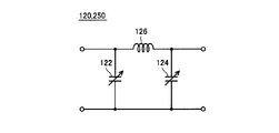
- FIG. 2 is a circuit diagram showing an example of the circuit configuration of the impedance matching unit 120.
- impedance matching unit 120 includes variable capacitors 122 and 124 and a coil 126.
- Variable capacitor 122 is connected in parallel to power supply device 110 (FIG. 1).
- Variable capacitor 124 is connected in parallel to primary coil 130 (FIG. 1).
- Coil 126 is connected between connection nodes of variable capacitors 122 and 124 in one of a pair of power lines arranged between power supply device 110 and primary coil 130.
- impedance matching unit 120 the impedance is changed by changing the capacity of at least one of the variable capacitors 122 and 124 in accordance with a command received from the ECU 160 (FIG. 1). Thereby, impedance matching unit 120 matches the input impedance of the resonance system with the output impedance of power supply device 110 in accordance with a command received from ECU 160.
- the coil 126 may be a variable coil, and the impedance may be changed by changing the inductance of the variable coil.
- primary coil 130 is disposed substantially coaxially with primary self-resonant coil 140 at a predetermined interval from primary self-resonant coil 140.
- Primary coil 130 is magnetically coupled to primary self-resonant coil 140 by electromagnetic induction, and supplies high-frequency power supplied from power supply device 110 to primary self-resonant coil 140 by electromagnetic induction.
- the primary self-resonant coil 140 receives electric power from the primary coil 130 by electromagnetic induction, and transmits power to the secondary self-resonant coil 210 by resonating with a secondary self-resonant coil 210 (described later) mounted on the vehicle 200 via an electromagnetic field. To do.
- the primary self-resonant coil 140 is provided with a capacitor 150. Capacitor 150 is connected between both ends of primary self-resonant coil 140, for example. Then, the coil diameter and the number of turns of primary self-resonant coil 140 and the capacitance of capacitor 150 are appropriately designed so that the Q value (for example, Q> 100), the degree of coupling ⁇ , and the like are increased.
- the primary coil 130 is provided to facilitate power supply from the power supply device 110 to the primary self-resonant coil 140, and the power supply device 110 is directly connected to the primary self-resonant coil 140 without providing the primary coil 130. May be. Further, the stray capacitance of the primary self-resonant coil 140 may be used so that the capacitor 150 is not provided.
- ECU 160 receives detection values of reflected power and traveling wave power from power sensor 115 when power is supplied from power supply facility 100 to vehicle 200, and receives a power reception status on vehicle 200 side received by communication device 170.
- the power reception status of the vehicle 200 includes information such as a received voltage, a received current, and a received power in the vehicle 200.
- ECU 160 executes a predetermined process by a software process by executing a program stored in advance by a CPU (Central Processing Unit) and / or a hardware process by a dedicated electronic circuit.
- CPU Central Processing Unit
- ECU 160 controls the operation of power supply device 110.
- ECU 160 adjusts the impedance of impedance matching unit 120 prior to charging power storage device 280 (described later) of vehicle 200 by power supply facility 100.
- the ECU 160 subsequently transmits a command for instructing the start of adjustment of the impedance matching unit 250 (described later) to the vehicle 200 on the vehicle 200 side.
- ECU 160 also transmits information necessary for adjustment of impedance matching unit 250 of vehicle 200 such as an adjustment value of impedance matching unit 120 and a detection value of reflected power to vehicle 200 by communication device 170.
- ECU 160 estimates the amount of misalignment of secondary self-resonant coil 210 with respect to primary self-resonant coil 140 (hereinafter simply referred to as “the amount of misalignment”), and based on the estimated amount of misalignment, impedance is determined. The impedance of the matching unit 120 is adjusted. Regarding the estimation method of the positional deviation amount, ECU 160 estimates the positional deviation amount based on the power reception status of vehicle 200 and the reflected power to power supply device 110.
- the primary self-resonant coil 140 and the secondary self-resonant coil 210 are arranged so that their central axes are parallel to each other, and the offset amount of the central axis of the secondary self-resonant coil 210 with respect to the central axis of the primary self-resonant coil 140 Is referred to as a “positional deviation amount”.
- the communication device 170 is a communication interface for communicating with the vehicle 200.
- Information on the power supply equipment 100 side such as the adjustment value of the matching unit 120 and reflected power, a command instructing the start of full-scale power supply for charging the power storage device 280, and the like are transmitted to the vehicle 200.
- the communication device 170 receives from the vehicle 200 a power reception status on the vehicle 200 side, a charging state of the power storage device 280 (hereinafter also referred to as “SOC (State Of Charge)”), a signal indicating completion of adjustment on the vehicle 200 side, and the like. To do.
- SOC State Of Charge
- vehicle 200 includes secondary self-resonant coil 210, capacitor 220, secondary coil 230, switching device 240, impedance matching device 250, rectifier 260, charger 270, power storage device 280, power Output device 285.
- Vehicle 200 further includes an ECU 290, a communication device 300, a voltage sensor 310, and a current sensor 312.
- the secondary self-resonant coil 210 receives power from the primary self-resonant coil 140 by resonating with the primary self-resonant coil 140 of the power supply facility 100 via an electromagnetic field.
- the secondary self-resonant coil 210 is provided with a capacitor 220.
- Capacitor 220 is connected between both ends of secondary self-resonant coil 210, for example. Then, the coil diameter and the number of turns of secondary self-resonant coil 210 and the capacitance of capacitor 220 are appropriately designed so that the Q value (for example, Q> 100), the degree of coupling ⁇ , and the like are increased.
- the secondary coil 230 is disposed substantially coaxially with the secondary self-resonant coil 210 at a predetermined interval from the secondary self-resonant coil 210.
- the secondary coil 230 can be magnetically coupled to the secondary self-resonant coil 210 by electromagnetic induction, takes out the electric power received by the secondary self-resonant coil 210 by electromagnetic induction, and outputs it to the switching device 240.
- the secondary coil 230 is provided for facilitating extraction of electric power from the secondary self-resonant coil 210, and the switching device 240 is connected to the secondary self-resonant coil 210 without providing the secondary coil 230. You may connect directly. Further, the configuration may be such that the capacitor 220 is not provided by using the stray capacitance of the secondary self-resonant coil 210.
- the switching device 240 is provided between the secondary coil 230 and the impedance matching device 250.
- Switching device 240 includes relays 242 and 244 and a resistance element 246.
- the relay 242 is provided on the power line between the secondary coil 230 and the impedance matching device 250.
- Relay 244 and resistance element 246 are connected in series between the power line pair between secondary coil 230 and impedance matching device 250 on the side of secondary coil 230 relative to relay 242.
- the relays 242 and 244 are turned on and off, respectively.
- the impedance matching device 120 is adjusted in the power supply facility 100
- the relays 242 and 244 are turned off and on, respectively.
- the load of vehicle 200 whose impedance varies with the SOC of power storage device 280 is disconnected from the resonance system, and impedance adjustment can be performed stably in power supply facility 100.
- the relays 242 and 244 are turned on and off, respectively.
- the impedance matching unit 250 is electrically connected to the resonance system.
- the impedance matching unit 250 is provided between the switching device 240 and the rectifier 260 and is configured to be able to change the internal impedance. Impedance matching device 250 matches the input impedance of the resonance system with the output impedance of power supply device 110 by changing the impedance according to a command received from ECU 290.
- the configuration of the impedance matching unit 250 is also the same as that of the impedance matching unit 120 of the power supply facility 100 shown in FIG.
- the rectifier 260 rectifies the electric power (alternating current) output from the secondary coil 230.
- Charger 270 converts the DC power output from rectifier 260 into a charging voltage for power storage device 280 and outputs the voltage to power storage device 280.
- Power storage device 280 is a rechargeable DC power source, and is composed of, for example, a secondary battery such as lithium ion or nickel metal hydride.
- Power storage device 280 stores power received from charger 270 and also stores regenerative power generated by power output device 285. Then, power storage device 280 supplies the stored power to power output device 285. Note that a large-capacity capacitor can also be used as the power storage device 280.
- the power output device 285 generates the driving force for driving the vehicle 200 using the electric power stored in the power storage device 280.
- power output device 285 includes, for example, an inverter that receives electric power from power storage device 280, a motor driven by the inverter, a drive wheel driven by the motor, and the like.
- Power output device 285 may include a generator for charging power storage device 280 and an engine capable of driving the generator.
- the voltage sensor 310 detects the voltage V output from the secondary coil 230 and outputs the detected value to the ECU 290.
- Current sensor 312 detects current I output from secondary coil 230 and outputs the detected value to ECU 290.
- ECU 290 receives detected values of voltage V and current I from voltage sensor 310 and current sensor 312, respectively.
- ECU 290 receives various commands and information transmitted from power supply facility 100 from communication device 300.
- ECU 290 executes a predetermined process by a software process by executing a program stored in advance by a CPU (Central Processing Unit) and / or a hardware process by a dedicated electronic circuit.
- CPU Central Processing Unit
- ECU 290 adjusts the impedance of impedance matching device 250 in accordance with an adjustment start command received from power supply facility 100. Then, when the adjustment of impedance matching device 250 is completed, ECU 290 charges power storage device 280 by controlling charger 270. The processing executed by ECU 290 will be described in detail later.
- the communication device 300 is a communication interface for communicating with the power supply facility 100.
- the primary self-resonant coil 140 and the secondary self-resonant coil 210 resonate via an electromagnetic field, so that power is supplied from the power supply facility 100 to the vehicle 200.
- An impedance matching device for matching the input impedance of the resonance system with the output impedance of the power supply apparatus 110 is provided in both the power supply facility 100 and the vehicle 200.
- the impedance of the impedance matching unit 120 is adjusted in the power supply facility 100 prior to the adjustment in the vehicle 200.
- a command instructing the start of the adjustment of the impedance matching unit 250 of the vehicle 200 is transmitted from the power supply facility 100 to the vehicle 200, and the impedance of the impedance matching unit 250 is adjusted in the vehicle 200. . That is, in this non-contact power feeding system, first, the impedance matching unit 120 is adjusted in the power feeding facility 100, and then the impedance matching unit 250 is adjusted in the vehicle 200.
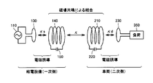
- FIG. 3 is a diagram for explaining the principle of power transmission by the resonance method.
- this resonance method in the same way as two tuning forks resonate, two LC resonance coils having the same natural frequency resonate in an electromagnetic field (near field), and thereby, from one coil. Electric power is transmitted to the other coil via an electromagnetic field.
- the primary coil 130 is connected to the power supply device 110, and high frequency power of 1 M to several tens MHz is supplied to the primary self-resonant coil 140 that is magnetically coupled to the primary coil 130 by electromagnetic induction.
- Primary self-resonant coil 140 forms an LC resonator with capacitor 150 and resonates with secondary self-resonant coil 210 having the same resonance frequency as primary self-resonant coil 140 via an electromagnetic field (near field). Then, energy (electric power) moves from the primary self-resonant coil 140 to the secondary self-resonant coil 210 via the electromagnetic field.
- the energy (power) transferred to the secondary self-resonant coil 210 is taken out by the secondary coil 230 that is magnetically coupled to the secondary self-resonant coil 210 by electromagnetic induction, and is supplied to the load 350 after the rectifier 260 (FIG. 1). Supplied.
- power transmission by the resonance method is realized when the Q value indicating the resonance intensity between the primary self-resonant coil 140 and the secondary self-resonant coil 210 is greater than 100, for example.
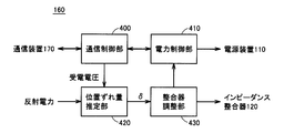
- FIG. 4 is a functional block diagram of the ECU 160 of the power supply facility 100.
- ECU 160 includes a communication control unit 400, a power control unit 410, a positional deviation amount estimation unit 420, and a matching unit adjustment unit 430.
- the communication control unit 400 controls communication with the vehicle 200 by the communication device 170 (FIG. 1). Specifically, communication control unit 400 transmits an adjustment processing start command to vehicle 200 prior to charging power storage device 280 of vehicle 200 by power supply facility 100. When the adjustment of the impedance matching unit 120 by the matching unit adjustment unit 430 is completed, the communication control unit 400 instructs the start of adjustment of the vehicle 200 and information on the power supply equipment 100 side necessary for the adjustment (impedance matching unit). 120 adjustment values, reflected power detection values, etc.) are transmitted to the vehicle 200. Furthermore, the communication control unit 400 receives the power reception status on the vehicle 200 side from the vehicle 200.
- the power control unit 410 controls the power supplied to the vehicle 200 by controlling the power supply device 110.
- power control unit 410 controls power supply device 110 to output smaller power (adjustment power) than during full-scale power supply for charging power storage device 280.
- the positional deviation amount estimation unit 420 receives the secondary self-resonant coil 140 from the self-resonant coil 140 based on the received voltage included in the power receiving status of the vehicle 200 received from the vehicle 200 and the reflected power detected by the power sensor 115 (FIG. 1). The positional deviation amount ⁇ of the resonance coil 210 is estimated.
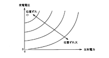
- FIG. 5 is a diagram showing the relationship between the received voltage and the reflected power and the positional deviation amount ⁇ .
- positional deviation amount ⁇ when positional deviation amount ⁇ is small, the received voltage in vehicle 200 is high, and the reflected power in power supply facility 100 is small.
- positional deviation amount ⁇ when the positional deviation amount ⁇ is large, the received voltage is low and the reflected power is large.
- a map or the like is created by previously obtaining the relationship between the received voltage and reflected power and the amount of positional deviation, and the map or the like is used to detect the power transmission from the power supply facility 100 to the vehicle 200.
- a positional deviation amount ⁇ is estimated based on the received voltage and the reflected power.
- the received power can be used instead of the received voltage. That is, when the positional deviation amount ⁇ is small, the received power in the vehicle 200 is large and the reflected power in the power supply facility 100 is small. On the other hand, when the positional deviation amount ⁇ is large, the received power is small and the reflected power is large. Therefore, a map or the like is created by previously obtaining the relationship between the received power and reflected power and the amount of positional deviation, and the received power detected when power is transmitted from the power supply facility 100 to the vehicle 200 using the map or the like. The positional deviation amount ⁇ may be estimated based on the reflected power.
- matching unit adjustment section 430 matches the input impedance of the resonance system and the output impedance of power supply apparatus 110 based on position shift amount ⁇ estimated by position shift amount estimation section 420.
- the impedance of the impedance matching unit 120 is adjusted.
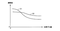
- FIG. 6 is a diagram showing an example of the relationship between the positional deviation amount ⁇ and the adjustment value of the impedance matching unit 120.
- C1 and C2 indicate adjustment values of variable capacitors 122 and 124 (FIG. 2), respectively.
- the adjustment values C1 and C2 change depending on the positional deviation amount ⁇ . Accordingly, the relationship between the positional deviation amount ⁇ and the adjustment values C1 and C2 is obtained in advance and a map or the like is created. Based on the positional deviation amount ⁇ estimated based on the received voltage and the reflected power using the map or the like. Thus, adjustment values C1 and C2 are determined.
- a command for instructing start of adjustment on vehicle 200 side is transmitted to vehicle 200 by communication control unit 400.
- power control unit 410 controls power supply device 110 to perform full-scale power supply for charging power storage device 280 of vehicle 200.
- FIG. 7 is a functional block diagram of ECU 290 of vehicle 200.
- ECU 290 includes a communication control unit 500, an adjustment control unit 510, a positional deviation amount estimation unit 520, and a matching unit adjustment unit 530.
- the communication control unit 500 controls communication with the power supply facility 100 by the communication device 300 (FIG. 1). Specifically, the communication control unit 500 transmits the power reception status from the power supply facility 100 to the power supply facility 100.
- the communication control unit 500 also includes an adjustment processing start command, a command for instructing the vehicle 200 to start adjustment, information on the power supply equipment 100 side necessary for the adjustment (adjustment value of the impedance matching unit 120 and detection value of reflected power). ) And the like are received from the power supply facility 100.
- the adjustment control unit 510 turns off and on the relays 242 and 244 (FIG. 1) of the switching device 240 when an adjustment processing start command is received. That is, adjustment control unit 510 disconnects the load (power storage device 280) of vehicle 200 from the resonance system and electrically connects resistance element 246 in response to the adjustment processing start command. In addition, when receiving an instruction to start adjustment of vehicle 200, adjustment control unit 510 turns on and off relays 242 and 244 of switching device 240, respectively.
- misregistration amount estimation unit 520 Based on the received voltage detected by voltage sensor 310 (FIG. 1), the detected value of reflected power received from vehicle 200, and the adjustment value of impedance matching unit 120, misregistration amount estimation unit 520 applies to primary self-resonant coil 140. The positional deviation amount ⁇ of the secondary self-resonant coil 210 is estimated.
- FIG. 8 is a diagram for explaining an example of a method of estimating the positional deviation amount ⁇ by the positional deviation amount estimation unit 520 shown in FIG.
- misregistration amount estimation section 520 estimates misregistration amount ⁇ using the relationship shown in FIG. That is, in FIG. 8, the vertical axis represents the received voltage, and the horizontal axis represents the reflected power.
- the positional deviation amount ⁇ is small, the received voltage in the vehicle 200 is high, and the reflected power in the power supply facility 100 is small.
- the positional deviation amount ⁇ is large, the received voltage is low and the reflected power is large.
- matching unit adjustment unit 530 matches the input impedance of the resonance system and the output impedance of power supply device 110 based on positional shift amount ⁇ estimated by positional shift amount estimation unit 520.
- the impedance of the impedance matching device 250 is adjusted.
- FIG. 9 is a diagram showing an example of the relationship between the positional deviation amount ⁇ and the adjustment value of the impedance matching unit 250.
- C3 and C4 indicate adjustment values of variable capacitors 122 and 124 (FIG. 2) of impedance matching unit 250, respectively.
- the adjustment values C3 and C4 change depending on the positional deviation amount ⁇ .
- the relationship between the positional deviation amount ⁇ and the adjustment values C3 and C4 is obtained in advance and a map or the like is created.
- adjustment values C3 and C4 are determined.
- FIG. 10 is a flowchart for explaining the process flow of the wireless power supply system.
- the ECU 160 of the power supply facility 100 transmits an adjustment processing start command to the vehicle 200 (step S10).
- ECU 160 receives a signal indicating completion of connection of resistance element 246 in vehicle 200 in response to the adjustment processing start command from vehicle 200 (YES in step S20)
- ECU 160 controls power supply device 110 to output adjustment power.
- this adjustment power is a predetermined power smaller than that at the time of full-scale power supply for charging power storage device 280.
- ECU 160 receives the power reception status (power reception voltage, power reception current, power reception, etc.) of vehicle 200 from vehicle 200 (step S40). Further, ECU 160 receives the reflected power to power supply device 110 detected by power sensor 115 from power sensor 115 (step S50).
- ECU 160 receives the received power reception voltage using a positional deviation amount estimation map (FIG. 5) prepared in advance showing the relationship between the received voltage of vehicle 200 and the reflected power at power supply facility 100 and the positional deviation amount. Based on the detected values of the detected reflected power, the positional deviation amount ⁇ is estimated (step S60). Further, ECU 160 uses a matching unit adjustment map (FIG. 6) prepared in advance showing the relationship between the amount of displacement of secondary self-resonant coil 210 relative to primary self-resonant coil 140 and the adjustment value of impedance matching unit 120. The impedance matching unit 120 is adjusted based on the positional deviation amount ⁇ estimated in step S60 (step S70).
- a positional deviation amount estimation map (FIG. 5) prepared in advance showing the relationship between the received voltage of vehicle 200 and the reflected power at power supply facility 100 and the positional deviation amount.
- the positional deviation amount ⁇ is estimated (step S60).
- ECU 160 uses a matching unit adjustment map (FIG. 6) prepared in advance
- the ECU 160 transmits an adjustment command for instructing the adjustment of the impedance matching unit 250 in the vehicle 200 to the vehicle 200 (step S80). Further, ECU 160 transmits information on the power feeding equipment 100 side (detected value of reflected power, impedance adjustment value, etc.) to vehicle 200 (step S90).
- ECU 160 determines whether or not adjustment of impedance matching device 250 has been completed in vehicle 200 (step S100). If it is determined that the adjustment on the vehicle 200 side is completed (YES in step S100), ECU 160 determines whether the reflected power and the received power of vehicle 200 are within a predetermined range (step S110). This determination process is for determining whether the magnitudes of the reflected power and the received power are appropriate for the power (traveling wave power) output from the power supply apparatus 110.
- ECU 160 controls power supply device 110 to output the charging power for charging power storage device 280 (Step S120).
- ECU 160 stops power supply device 110 and stops charging power storage device 280 by power supply facility 100. (Step S130).
- ECU 290 of vehicle 200 receives the adjustment processing start command from power supply facility 100 (YES in step S210), it turns off and on relays 242, 244 of switching device 240, respectively. Thereby, the resistance element 246 is electrically connected, and the ECU 290 transmits a connection completion signal to the power supply facility 100 (step S220).
- the ECU 290 transmits the power reception status of the vehicle 200 including the power reception voltage detected by the voltage sensor 310 to the power supply facility 100 (step S230). ).
- ECU 290 when ECU 290 receives an adjustment command for instructing adjustment of impedance matching unit 250 from power supply equipment 100 (YES in step S240), it turns on and off relays 242, 244, respectively. Thereby, the impedance matching device 250 is electrically connected, and the resistance element 246 is disconnected (step S250). Further, the ECU 290 receives information on the power supply facility 100 side (such as a reflected power detection value and an impedance adjustment value) from the power supply facility 100 (step S260).
- information on the power supply facility 100 side such as a reflected power detection value and an impedance adjustment value
- ECU 290 uses the positional deviation amount estimation map prepared in advance (FIG. 8), based on the received adjustment value of impedance matching unit 120, the detected value of reflected power, and the detected received voltage. ⁇ is estimated (step S270). As described above, the positional deviation amount estimation map is prepared in advance for each adjustment value of the impedance matching unit 120 of the power supply facility 100.
- the ECU 290 adjusts the impedance matching unit 250 based on the positional deviation amount ⁇ estimated in step S270 using a matching unit adjustment map (FIG. 9) prepared in advance (step S280).
- ECU 290 transmits an adjustment completion signal to vehicle 200 (step S290).
- power supply facility 100 and vehicle 200 include impedance matching units 120 and 250, respectively.
- the impedance adjustment range is wider than when the impedance matching device is provided only in one of the power supply facility 100 and the vehicle 200.
- the impedance matching unit 120 Prior to the adjustment of the impedance matching unit 250 in the vehicle 200, the impedance matching unit 120 is adjusted in the power supply facility 100, and after the adjustment of the impedance matching unit 120, the impedance matching unit 250 is adjusted in the vehicle 200. Thereby, the reflected power is suppressed in the power supply facility 100. Therefore, according to the first embodiment, the power transmission efficiency can be improved by expanding the adjustment range of the impedance, and the power supply apparatus 110 can be prevented from being damaged by suppressing the reflected power in the power supply facility 100. .
- the adjustment of the impedance matching unit 120 of the power supply facility 100 is performed by the ECU 160 of the power supply facility 100, and the vehicle 200
- the adjustment of the impedance matching unit 250 is performed by the ECU 290 of the vehicle 200. Therefore, according to this Embodiment 1, the responsiveness of impedance adjustment is high, and adjustment can be implemented in a short time.
- the displacement amount ⁇ is estimated based on the received voltage and the reflected power using the map in the vehicle 200 as well.
- the displacement amount ⁇ estimated by the ECU 160 of the power supply facility 100 is calculated using the map. It may be transmitted to 200 and used in the vehicle 200.
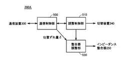
- FIG. 11 is a functional block diagram of the ECU of the vehicle 200 in the second embodiment.
- ECU 290A does not include a positional deviation amount estimation unit 520 in the configuration of ECU 290 in the first embodiment shown in FIG. That is, the matching unit adjustment unit 530 receives the positional deviation amount ⁇ estimated from the power supply facility 100 received from the power supply facility 100 from the communication control unit 500.
- Matching device adjustment section 530 adjusts the impedance of impedance matching device 250 so that the input impedance of the resonance system matches the output impedance of power supply device 110 based on the received positional deviation amount ⁇ .
- ECU 290A The other functions of ECU 290A are the same as those of ECU 290 in the first embodiment shown in FIG.
- FIG. 12 is a flowchart for explaining the processing flow of the non-contact power feeding system according to the second embodiment. Referring to FIG. 12, this flowchart includes step S95 in place of step S90 and includes step S265 in place of steps S260 and S270 in the flowchart shown in FIG.
- ECU 160 of power supply facility 100 further determines the amount of positional deviation ⁇ estimated in step S60 as the vehicle. 200 (step S95).
- step S250 when impedance matching unit 250 is electrically connected and resistance element 246 is disconnected, ECU 290 of vehicle 200 receives displacement ⁇ transmitted from power supply facility 100 (step S265). ). Then, ECU 290 advances the process to step S280, and adjusts impedance matching unit 250 based on positional deviation amount ⁇ received from power supply facility 100.
- the positional deviation amount ⁇ is estimated in the power feeding facility 100 and the estimated value is transmitted to the vehicle 200.
- the positional deviation amount ⁇ is estimated in the vehicle 200, and the estimated value is used as the power feeding facility.
- 100 may be used to adjust the impedance matching unit 120 of the power supply facility 100.
- the estimation calculation of the positional deviation amount ⁇ can be omitted in either the power supply facility 100 or the vehicle 200, so that the adjustment processing time can be shortened.
- the switching device 240 including the adjusting resistance element 246 is provided between the secondary coil 230 and the impedance matching device 250.
- the rectifier 260 and the charger A switching device 240 may be provided between the H.270 and the H.270.
- FIG. 13 is an overall configuration diagram of the non-contact power feeding system according to the third embodiment.
- this non-contact power feeding system includes a vehicle 200 ⁇ / b> A instead of vehicle 200 in the configuration of the non-contact power feeding system in the first embodiment shown in FIG. 1.
- the switching device 240 is provided between the rectifier 260 and the charger 270.
- the impedance matching unit 120 is adjusted first in the power supply equipment 100, and after the impedance matching unit 120 is adjusted, the impedance matching unit 250 is adjusted in the vehicle 200.
- the resistance element 246 is electrically connected by the switching device 240 even when the impedance matching unit 250 of the vehicle 200 is adjusted. When the adjustment of the impedance matching device 250 is completed, the resistance element 246 is disconnected and the charger 270 is electrically connected.
- vehicle 200A is the same as that of vehicle 200 of the first embodiment shown in FIG.
- the above-described configuration can also be applied to the second embodiment.
- power is transmitted by resonating the primary self-resonant coil 140 of the power supply facility 100 and the secondary self-resonant coil 210 of the vehicle 200, but power is transmitted by a pair of high dielectric disks.
- a unit and a power receiving unit may be configured.
- the high dielectric disk is made of a high dielectric constant material, and for example, TiO 2 , BaTi 4 O 9 , LiTaO 3 or the like is used.
- the primary coil 130, the primary self-resonant coil 140, and the capacitor 150 form one example of the “power transmission unit” in the present invention.
- secondary self-resonant coil 210, capacitor 220, and secondary coil 230 form one embodiment of the “power receiving unit” in the present invention.
- power storage device 280 corresponds to an example of “load” in the present invention.
- 100 power supply equipment 110 power supply device, 115 power sensor, 120, 250 impedance matcher, 122, 124 variable capacitor, 126 coil, 130 primary coil, 140 primary self-resonant coil, 150, 220 capacitor, 160, 290, 290A ECU, 170, 300 communication device, 200, 200A vehicle, 230 secondary coil, 240 switching device, 242, 244 relay, 246 resistance element, 260 rectifier, 270 charger, 280 power storage device, 285 power output device, 310 voltage sensor, 312 Current sensor, 350 load, 400, 500 communication control unit, 410 power control unit, 420, 520 misregistration amount estimation unit, 430, 530 matching unit control unit, 510 adjustment control unit.
Landscapes
- Engineering & Computer Science (AREA)
- Power Engineering (AREA)
- Computer Networks & Wireless Communication (AREA)
- Transportation (AREA)
- Mechanical Engineering (AREA)
- Life Sciences & Earth Sciences (AREA)
- Sustainable Development (AREA)
- Sustainable Energy (AREA)
- Signal Processing (AREA)
- Electric Propulsion And Braking For Vehicles (AREA)
- Charge And Discharge Circuits For Batteries Or The Like (AREA)
Abstract
Description
また、この発明によれば、車両は、給電設備から非接触で受電可能な車両である。給電設備は、第1のインピーダンス可変装置を含む。第1のインピーダンス可変装置は、電源装置と送電ユニットとの間に設けられる。車両は、受電ユニットと、負荷と、第2のインピーダンス可変装置と、制御装置とを備える。受電ユニットは、送電ユニットと電磁場を介して共鳴することにより送電ユニットから非接触で受電する。負荷は、受電ユニットにより受電された電力を受ける。第2のインピーダンス可変装置は、受電ユニットと負荷との間に設けられる。制御装置は、第2のインピーダンス可変装置を調整する。そして、制御装置は、給電設備において第1のインピーダンス可変装置の調整後、第2のインピーダンス可変装置を調整する。
図1は、この発明の実施の形態1による非接触給電システムの全体構成図である。図1を参照して、この非接触給電システムは、給電設備100と、車両200とを備える。
上記の実施の形態1では、車両200においても、マップを用いて、受電電圧および反射電力に基づいて位置ずれ量δを推定したが、給電設備100のECU160によって推定された位置ずれ量δを車両200へ送信して車両200で用いるようにしてもよい。
上記の実施の形態1,2では、車両200において、調整用の抵抗素子246を含む切替装置240は、二次コイル230とインピーダンス整合器250との間に設けられたが、整流器260と充電器270との間に切替装置240を設けてもよい。
Claims (21)
- 給電設備(100)と、
前記給電設備から非接触で受電する受電装置(200)とを備え、
前記給電設備は、
所定の周波数を有する電力を発生する電源装置(110)と、
前記電源装置から電力を受け、前記受電装置と電磁場を介して共鳴することにより前記受電装置へ非接触で送電するための送電ユニット(130,140,150)と、
前記電源装置と前記送電ユニットとの間に設けられる第1のインピーダンス可変装置(120)と、
前記第1のインピーダンス可変装置を調整する第1の制御装置(160)とを含み、
前記受電装置は、
前記送電ユニットと前記電磁場を介して共鳴することにより前記送電ユニットから非接触で受電するための受電ユニット(210,220,230)と、
前記受電ユニットにより受電された電力を受ける負荷(280)と、
前記受電ユニットと前記負荷との間に設けられる第2のインピーダンス可変装置(250)と、
前記第2のインピーダンス可変装置を調整する第2の制御装置(290)とを含み、
前記第1の制御装置は、前記受電装置における前記第2のインピーダンス可変装置の調整に先立って前記第1のインピーダンス可変装置を調整し、
前記第2の制御装置は、前記第1の制御装置による前記第1のインピーダンス可変装置の調整後、前記第2のインピーダンス可変装置を調整する、非接触給電システム。 - 前記給電設備は、第1の通信装置(170)をさらに含み、
前記受電装置は、前記第1の通信装置と通信可能な第2の通信装置(300)をさらに含み、
前記第2の通信装置は、前記受電装置側の情報を前記給電設備へ送信し、
前記第1の制御装置は、前記第1の通信装置によって受信される前記受電装置側の情報を利用して前記第1のインピーダンス可変装置を調整し、
前記第1の通信装置は、前記給電設備側の情報を前記受電装置へ送信し、
前記第2の制御装置は、前記第2の通信装置によって受信される前記給電設備側の情報を利用して前記第2のインピーダンス可変装置を調整する、請求項1に記載の非接触給電システム。 - 前記第1の制御装置は、前記受電装置側の情報に基づき推定される、前記送電ユニットに対する前記受電ユニットの位置ずれ量に基づいて前記第1のインピーダンス可変装置を調整し、
前記第1の通信装置は、前記推定された位置ずれ量を前記受電装置へ送信し、
前記第2の制御装置は、前記第2の通信装置によって受信される前記位置ずれ量に基づいて前記第2のインピーダンス可変装置を調整する、請求項2に記載の非接触給電システム。 - 前記受電装置は、
前記第1および第2のインピーダンス可変装置の調整時に前記受電ユニットと前記第2のインピーダンス可変装置との間の電力線対間に電気的に接続される抵抗素子(246)と、
前記第1および第2のインピーダンス可変装置の調整時に、前記電力線対間に前記抵抗素子を電気的に接続し、かつ、前記第2のインピーダンス可変装置を前記受電ユニットから電気的に切離すための切替装置(242,244)とをさらに含む、請求項1から請求項3のいずれか1項に記載の非接触給電システム。 - 前記受電装置は、
前記第2のインピーダンス可変装置と前記負荷との間に設けられ、前記受電ユニットにより受電された電力を整流する整流器(260)と、
前記第1および第2のインピーダンス可変装置の調整時に前記整流器と前記負荷との間の電力線対間に電気的に接続される抵抗素子(246)と、
前記第1および第2のインピーダンス可変装置の調整時に、前記電力線対間に前記抵抗素子を電気的に接続し、かつ、前記整流器から前記負荷を電気的に切離すための切替装置(242,244)とをさらに含む、請求項1から請求項3のいずれか1項に記載の非接触給電システム。 - 前記送電ユニットは、前記電源装置から電力を受けて前記電磁場を発生する一次自己共振コイル(140)を含み、
前記受電ユニットは、前記電磁場を介して前記一次自己共振コイルと共鳴することにより前記一次自己共振コイルから受電する二次自己共振コイル(210)を含む、請求項1から請求項3のいずれか1項に記載の非接触給電システム。 - 前記送電ユニットは、
前記電源装置から電力を受ける一次コイル(130)と、
前記一次コイルから電磁誘導により給電され、前記電磁場を発生する一次自己共振コイル(140)とを含み、
前記受電ユニットは、
前記電磁場を介して前記一次自己共振コイルと共鳴することにより前記一次自己共振コイルから受電する二次自己共振コイル(210)と、
前記二次自己共振コイルによって受電された電力を電磁誘導により取出して出力する二次コイル(230)とを含む、請求項1から請求項3のいずれか1項に記載の非接触給電システム。 - 前記受電装置は、車両に搭載される、請求項1から請求項3のいずれか1項に記載の非接触給電システム。
- 給電設備(100)から非接触で受電可能な車両であって、前記給電設備は、電源装置(110)と送電ユニット(130,140,150)との間に設けられる第1のインピーダンス可変装置(120)を含み、
前記送電ユニットと電磁場を介して共鳴することにより前記送電ユニットから非接触で受電するための受電ユニット(210,220,230)と、
前記受電ユニットにより受電された電力を受ける負荷(280)と、
前記受電ユニットと前記負荷との間に設けられる第2のインピーダンス可変装置(250)と、
前記第2のインピーダンス可変装置を調整する制御装置(290)とを備え、
前記制御装置は、前記給電設備において前記第1のインピーダンス可変装置の調整後、前記第2のインピーダンス可変装置を調整する、車両。 - 前記給電設備と通信可能な通信装置(300)をさらに備え、
前記制御装置は、前記通信装置によって受信される前記給電設備側の情報を利用して前記第2のインピーダンス可変装置を調整する、請求項9に記載の車両。 - 前記制御装置は、前記送電ユニットに対する前記受電ユニットの位置ずれ量に基づいて前記第2のインピーダンス可変装置を調整する、請求項10に記載の車両。
- 前記第1および第2のインピーダンス可変装置の調整時に前記受電ユニットと前記第2のインピーダンス可変装置との間の電力線対間に電気的に接続される抵抗素子(246)と、
前記第1および第2のインピーダンス可変装置の調整時に、前記電力線対間に前記抵抗素子を電気的に接続し、かつ、前記第2のインピーダンス可変装置を前記受電ユニットから電気的に切離すための切替装置(242,244)とをさらに備える、請求項9から請求項11のいずれか1項に記載の車両。 - 前記第2のインピーダンス可変装置と前記負荷との間に設けられ、前記受電ユニットにより受電された電力を整流する整流器(260)と、
前記第1および第2のインピーダンス可変装置の調整時に前記整流器と前記負荷との間の電力線対間に電気的に接続される抵抗素子(246)と、
前記第1および第2のインピーダンス可変装置の調整時に、前記電力線対間に前記抵抗素子を電気的に接続し、かつ、前記整流器から前記負荷を電気的に切離すための切替装置(242,244)とをさらに備える、請求項9から請求項11のいずれか1項に記載の車両。 - 前記送電ユニットは、前記電源装置から電力を受けて前記電磁場を発生する一次自己共振コイル(140)を含み、
前記受電ユニットは、前記電磁場を介して前記一次自己共振コイルと共鳴することにより前記一次自己共振コイルから受電する二次自己共振コイル(210)を含む、請求項9から請求項11のいずれか1項に記載の車両。 - 前記送電ユニットは、
前記電源装置から電力を受ける一次コイル(130)と、
前記一次コイルから電磁誘導により給電され、前記電磁場を発生する一次自己共振コイル(140)とを含み、
前記受電ユニットは、
前記電磁場を介して前記一次自己共振コイルと共鳴することにより前記一次自己共振コイルから受電する二次自己共振コイル(210)と、
前記二次自己共振コイルによって受電された電力を電磁誘導により取出して出力する二次コイル(230)とを含む、請求項9から請求項11のいずれか1項に記載の車両。 - 受電装置(200)へ非接触で送電可能な給電設備であって、前記受電装置は、受電ユニット(210,220,230)と前記受電ユニットにより受電された電力を受ける負荷(280)との間に設けられる第1のインピーダンス可変装置(250)を含み、
所定の周波数を有する電力を発生する電源装置(110)と、
前記電源装置から電力を受け、前記受電装置と電磁場を介して共鳴することにより前記受電装置へ非接触で送電するための送電ユニット(130,140,150)と、
前記電源装置と前記送電ユニットとの間に設けられる第2のインピーダンス可変装置(120)と、
前記第2のインピーダンス可変装置を調整する制御装置(160)とを備え、
前記制御装置は、前記受電装置における前記第1のインピーダンス可変装置の調整に先立って前記第2のインピーダンス可変装置を調整する、給電設備。 - 前記受電装置と通信可能な通信装置(170)をさらに備え、
前記制御装置は、前記通信装置によって受信される前記受電装置側の情報を利用して前記第2のインピーダンス可変装置を調整する、請求項16に記載の給電設備。 - 前記制御装置は、前記受電装置側の情報に基づき推定される、前記送電ユニットに対する前記受電ユニットの位置ずれ量に基づいて前記第2のインピーダンス可変装置を調整する、請求項17に記載の給電設備。
- 前記送電ユニットは、前記電源装置から電力を受けて前記電磁場を発生する一次自己共振コイル(140)を含み、
前記受電ユニットは、前記電磁場を介して前記一次自己共振コイルと共鳴することにより前記一次自己共振コイルから受電する二次自己共振コイル(210)を含む、請求項16から請求項18のいずれか1項に記載の給電設備。 - 前記送電ユニットは、
前記電源装置から電力を受ける一次コイル(130)と、
前記一次コイルから電磁誘導により給電され、前記電磁場を発生する一次自己共振コイル(140)とを含み、
前記受電ユニットは、
前記電磁場を介して前記一次自己共振コイルと共鳴することにより前記一次自己共振コイルから受電する二次自己共振コイル(210)と、
前記二次自己共振コイルによって受電された電力を電磁誘導により取出して出力する二次コイル(230)とを含む、請求項16から請求項18のいずれか1項に記載の給電設備。 - 給電設備(100)から受電装置(200)へ非接触で給電する非接触給電システムの制御方法であって、
前記給電設備は、
所定の周波数を有する電力を発生する電源装置(110)と、
前記電源装置から電力を受け、前記受電装置と電磁場を介して共鳴することにより前記受電装置へ非接触で送電するための送電ユニット(130,140,150)と、
前記電源装置と前記送電ユニットとの間に設けられる第1のインピーダンス可変装置(120)とを備え、
前記受電装置は、
前記送電ユニットと前記電磁場を介して共鳴することにより前記送電ユニットから非接触で受電するための受電ユニット(210,220,230)と、
前記受電ユニットにより受電された電力を受ける負荷(280)と、
前記受電ユニットと前記負荷との間に設けられる第2のインピーダンス可変装置(250)とを備え、
前記制御方法は、
前記第2のインピーダンス可変装置の調整に先立って前記第1のインピーダンス可変装置を調整するステップと、
前記第1のインピーダンス可変装置の調整後、前記第2のインピーダンス可変装置を調整するステップとを含む、非接触給電システムの制御方法。
Priority Applications (5)
| Application Number | Priority Date | Filing Date | Title |
|---|---|---|---|
| JP2012549543A JP5648694B2 (ja) | 2010-12-24 | 2010-12-24 | 非接触給電システム及び給電設備 |
| PCT/JP2010/073323 WO2012086051A1 (ja) | 2010-12-24 | 2010-12-24 | 非接触給電システム、車両、給電設備および非接触給電システムの制御方法 |
| EP10861029.6A EP2658084B1 (en) | 2010-12-24 | 2010-12-24 | Contactless power supply system and contactless power supply system control method |
| US13/992,093 US9634733B2 (en) | 2010-12-24 | 2010-12-24 | Contactless power feeding system, vehicle, power feeding facility and method of controlling contactless power feeding system |
| CN201080070928.7A CN103270669B (zh) | 2010-12-24 | 2010-12-24 | 非接触供电系统、车辆、供电设备及非接触供电系统的控制方法 |
Applications Claiming Priority (1)
| Application Number | Priority Date | Filing Date | Title |
|---|---|---|---|
| PCT/JP2010/073323 WO2012086051A1 (ja) | 2010-12-24 | 2010-12-24 | 非接触給電システム、車両、給電設備および非接触給電システムの制御方法 |
Publications (1)
| Publication Number | Publication Date |
|---|---|
| WO2012086051A1 true WO2012086051A1 (ja) | 2012-06-28 |
Family
ID=46313352
Family Applications (1)
| Application Number | Title | Priority Date | Filing Date |
|---|---|---|---|
| PCT/JP2010/073323 Ceased WO2012086051A1 (ja) | 2010-12-24 | 2010-12-24 | 非接触給電システム、車両、給電設備および非接触給電システムの制御方法 |
Country Status (5)
| Country | Link |
|---|---|
| US (1) | US9634733B2 (ja) |
| EP (1) | EP2658084B1 (ja) |
| JP (1) | JP5648694B2 (ja) |
| CN (1) | CN103270669B (ja) |
| WO (1) | WO2012086051A1 (ja) |
Cited By (9)
| Publication number | Priority date | Publication date | Assignee | Title |
|---|---|---|---|---|
| JP2012195993A (ja) * | 2011-03-15 | 2012-10-11 | Nagano Japan Radio Co | 受電装置および非接触型電力伝送装置 |
| WO2014007352A1 (ja) * | 2012-07-05 | 2014-01-09 | 株式会社 豊田自動織機 | 送電機器及び非接触電力伝送装置 |
| JP2014075883A (ja) * | 2012-10-03 | 2014-04-24 | Toyota Industries Corp | 受電機器、及び非接触電力伝送装置 |
| JP2014103751A (ja) * | 2012-11-19 | 2014-06-05 | Toshiba Corp | 無線電力伝送制御装置、送電装置、受電装置および無線電力伝送システム |
| JP2014529886A (ja) * | 2011-08-16 | 2014-11-13 | コメート グループ ゲーエムベーハー | 工作機械用回転伝送器 |
| CN105122589A (zh) * | 2013-04-23 | 2015-12-02 | 松下知识产权经营株式会社 | 无线电力输送装置 |
| JP2016067150A (ja) * | 2014-09-25 | 2016-04-28 | トヨタ自動車株式会社 | 受電装置 |
| EP2905873A4 (en) * | 2012-10-03 | 2016-08-10 | Toyota Jidoshokki Kk | ENERGY RECEIVING DEVICE, ENERGY TRANSMISSION DEVICE AND CONTACTLESS ENERGY TRANSMISSION DEVICE |
| US10277082B2 (en) | 2014-05-30 | 2019-04-30 | Ihi Corporation | Power-transmitting device and wireless power-supplying system |
Families Citing this family (18)
| Publication number | Priority date | Publication date | Assignee | Title |
|---|---|---|---|---|
| US8841881B2 (en) | 2010-06-02 | 2014-09-23 | Bryan Marc Failing | Energy transfer with vehicles |
| JP5338862B2 (ja) * | 2011-06-29 | 2013-11-13 | 株式会社ダイフク | 無接触給電設備 |
| US9893566B2 (en) * | 2011-06-30 | 2018-02-13 | Yazaki Corporation | Power supply system |
| DE102012214201A1 (de) * | 2012-08-09 | 2014-05-22 | Bayerische Motoren Werke Aktiengesellschaft | Positionierung mit funkbasiertem Schließsystem |
| JP5643270B2 (ja) * | 2012-09-13 | 2014-12-17 | トヨタ自動車株式会社 | 車両および非接触給電システム |
| WO2014041655A1 (ja) | 2012-09-13 | 2014-03-20 | トヨタ自動車株式会社 | 非接触給電システム、ならびにそれに用いられる送電装置および車両 |
| KR20160077196A (ko) * | 2013-10-31 | 2016-07-01 | 미쓰비시 덴끼 엔지니어링 가부시키가이샤 | 공진형 고주파 전원 장치 |
| JPWO2015063920A1 (ja) * | 2013-10-31 | 2017-03-09 | 三菱電機エンジニアリング株式会社 | 共振型高周波電源装置 |
| JP6217388B2 (ja) * | 2013-12-27 | 2017-10-25 | トヨタ自動車株式会社 | 受電装置およびそれを備える車両 |
| KR101943082B1 (ko) * | 2014-01-23 | 2019-04-18 | 한국전자통신연구원 | 무선 전력 송신 장치, 무선 전력 수신 장치, 및 무선 전력 전송 시스템 |
| CN106165244A (zh) | 2014-05-30 | 2016-11-23 | 株式会社Ihi | 非接触供电系统、受电装置及送电装置 |
| US9711972B2 (en) | 2015-03-27 | 2017-07-18 | Qualcomm Incorporated | Auxiliary receiver coil to adjust receiver voltage and reactance |
| US9647589B2 (en) * | 2015-06-22 | 2017-05-09 | Infineon Technologies Ag | Alternator with current measurement |
| US10873219B2 (en) * | 2016-09-30 | 2020-12-22 | Fuji Corporation | Contactless power supply device |
| DE102017202025A1 (de) * | 2017-02-09 | 2018-08-09 | Bayerische Motoren Werke Aktiengesellschaft | Verfahren zur Überprüfung einer Primär- oder Sekundäreinheit eines induktiven Ladesystems |
| CN107592138A (zh) * | 2017-09-26 | 2018-01-16 | 江苏和升智能科技有限公司 | 一种电力线自适应阻抗匹配方法 |
| CN120663764A (zh) * | 2018-06-29 | 2025-09-19 | 布鲁萨电子公司 | 初级回路装置、次级回路装置和用于感应式充电的系统 |
| JP7447457B2 (ja) * | 2019-12-12 | 2024-03-12 | 株式会社デンソー | 非接触給電システム |
Citations (7)
| Publication number | Priority date | Publication date | Assignee | Title |
|---|---|---|---|---|
| WO2010055381A1 (en) * | 2008-11-14 | 2010-05-20 | Toyota Jidosha Kabushiki Kaisha | Contactless power supply system and conrol method thereof |
| WO2010067763A1 (ja) * | 2008-12-09 | 2010-06-17 | 株式会社 豊田自動織機 | 非接触電力伝送装置及び非接触電力伝送装置における電力伝送方法 |
| JP2010141976A (ja) | 2008-12-09 | 2010-06-24 | Toyota Industries Corp | 非接触電力伝送装置 |
| JP2010141977A (ja) | 2008-12-09 | 2010-06-24 | Toyota Industries Corp | 非接触電力伝送装置における電力伝送方法及び非接触電力伝送装置 |
| US20100259109A1 (en) * | 2009-04-14 | 2010-10-14 | Sony Corporation | Power transmission device, power transmission method, power reception device, power reception method, and power transmission system |
| JP2010252497A (ja) * | 2009-04-14 | 2010-11-04 | Fujitsu Ten Ltd | 無線電力伝送装置および無線電力伝送方法 |
| EP2290782A2 (en) * | 2009-08-26 | 2011-03-02 | Sony Corporation | Non-contact electric power feeding apparatus, non-contact electric power receiving apparatus, non-contact electric power feeding method, non-contact electric power receiving method and non-contact electric power feeding system |
Family Cites Families (16)
| Publication number | Priority date | Publication date | Assignee | Title |
|---|---|---|---|---|
| SG54559A1 (en) * | 1996-09-13 | 1998-11-16 | Hitachi Ltd | Power transmission system ic card and information communication system using ic card |
| CN102983639B (zh) | 2005-07-12 | 2016-01-27 | 麻省理工学院 | 无线非辐射能量传递 |
| US7825543B2 (en) | 2005-07-12 | 2010-11-02 | Massachusetts Institute Of Technology | Wireless energy transfer |
| EP2130287A1 (en) | 2007-03-27 | 2009-12-09 | Massachusetts Institute of Technology | Wireless energy transfer |
| US9601261B2 (en) * | 2008-09-27 | 2017-03-21 | Witricity Corporation | Wireless energy transfer using repeater resonators |
| JP5375032B2 (ja) * | 2008-11-04 | 2013-12-25 | 株式会社豊田自動織機 | 非接触電力伝送装置及び非接触電力伝送装置の設計方法 |
| JP2010183814A (ja) * | 2009-02-09 | 2010-08-19 | Toyota Industries Corp | 非接触電力伝送装置 |
| JP4865001B2 (ja) | 2009-04-13 | 2012-02-01 | 株式会社日本自動車部品総合研究所 | 非接触給電設備、非接触受電装置および非接触給電システム |
| JP5120326B2 (ja) | 2009-04-17 | 2013-01-16 | 富士通モバイルコミュニケーションズ株式会社 | 携帯端末 |
| JP5362437B2 (ja) * | 2009-05-12 | 2013-12-11 | 長野日本無線株式会社 | 電力伝送システム |
| US8853995B2 (en) * | 2009-06-12 | 2014-10-07 | Qualcomm Incorporated | Devices for conveying wireless power and methods of operation thereof |
| JP2011142559A (ja) * | 2010-01-08 | 2011-07-21 | Sony Corp | 給電装置、受電装置、およびワイヤレス給電システム |
| EP2571140B1 (en) | 2010-05-14 | 2018-04-25 | Kabushiki Kaisha Toyota Jidoshokki | Resonance-type non-contact power supply system, and adjustment method for matching unit during charging of resonance-type non-contact power supply system |
| JP5458187B2 (ja) * | 2010-07-29 | 2014-04-02 | 株式会社豊田自動織機 | 共鳴型非接触給電システム |
| CN103068618B (zh) * | 2010-07-29 | 2015-06-17 | 株式会社丰田自动织机 | 谐振型非接触电力供应系统 |
| CN102640395B (zh) | 2010-12-01 | 2015-05-06 | 丰田自动车株式会社 | 非接触供电设备、车辆以及非接触供电系统的控制方法 |
-
2010
- 2010-12-24 JP JP2012549543A patent/JP5648694B2/ja active Active
- 2010-12-24 CN CN201080070928.7A patent/CN103270669B/zh not_active Expired - Fee Related
- 2010-12-24 US US13/992,093 patent/US9634733B2/en active Active
- 2010-12-24 EP EP10861029.6A patent/EP2658084B1/en not_active Not-in-force
- 2010-12-24 WO PCT/JP2010/073323 patent/WO2012086051A1/ja not_active Ceased
Patent Citations (8)
| Publication number | Priority date | Publication date | Assignee | Title |
|---|---|---|---|---|
| WO2010055381A1 (en) * | 2008-11-14 | 2010-05-20 | Toyota Jidosha Kabushiki Kaisha | Contactless power supply system and conrol method thereof |
| JP2010119246A (ja) | 2008-11-14 | 2010-05-27 | Toyota Motor Corp | 給電システム |
| WO2010067763A1 (ja) * | 2008-12-09 | 2010-06-17 | 株式会社 豊田自動織機 | 非接触電力伝送装置及び非接触電力伝送装置における電力伝送方法 |
| JP2010141976A (ja) | 2008-12-09 | 2010-06-24 | Toyota Industries Corp | 非接触電力伝送装置 |
| JP2010141977A (ja) | 2008-12-09 | 2010-06-24 | Toyota Industries Corp | 非接触電力伝送装置における電力伝送方法及び非接触電力伝送装置 |
| US20100259109A1 (en) * | 2009-04-14 | 2010-10-14 | Sony Corporation | Power transmission device, power transmission method, power reception device, power reception method, and power transmission system |
| JP2010252497A (ja) * | 2009-04-14 | 2010-11-04 | Fujitsu Ten Ltd | 無線電力伝送装置および無線電力伝送方法 |
| EP2290782A2 (en) * | 2009-08-26 | 2011-03-02 | Sony Corporation | Non-contact electric power feeding apparatus, non-contact electric power receiving apparatus, non-contact electric power feeding method, non-contact electric power receiving method and non-contact electric power feeding system |
Non-Patent Citations (1)
| Title |
|---|
| See also references of EP2658084A4 |
Cited By (12)
| Publication number | Priority date | Publication date | Assignee | Title |
|---|---|---|---|---|
| JP2012195993A (ja) * | 2011-03-15 | 2012-10-11 | Nagano Japan Radio Co | 受電装置および非接触型電力伝送装置 |
| JP2014529886A (ja) * | 2011-08-16 | 2014-11-13 | コメート グループ ゲーエムベーハー | 工作機械用回転伝送器 |
| WO2014007352A1 (ja) * | 2012-07-05 | 2014-01-09 | 株式会社 豊田自動織機 | 送電機器及び非接触電力伝送装置 |
| JP2014075883A (ja) * | 2012-10-03 | 2014-04-24 | Toyota Industries Corp | 受電機器、及び非接触電力伝送装置 |
| EP2905873A4 (en) * | 2012-10-03 | 2016-08-10 | Toyota Jidoshokki Kk | ENERGY RECEIVING DEVICE, ENERGY TRANSMISSION DEVICE AND CONTACTLESS ENERGY TRANSMISSION DEVICE |
| JP2014103751A (ja) * | 2012-11-19 | 2014-06-05 | Toshiba Corp | 無線電力伝送制御装置、送電装置、受電装置および無線電力伝送システム |
| CN105122589A (zh) * | 2013-04-23 | 2015-12-02 | 松下知识产权经营株式会社 | 无线电力输送装置 |
| US20160079951A1 (en) * | 2013-04-23 | 2016-03-17 | Panasonic Intellectual Property Management Co., Ltd. | Wireless power transmitter apparatus having power transmitter apparatus and power reception apparatus supplied with electric power energy via space |
| JPWO2014174783A1 (ja) * | 2013-04-23 | 2017-02-23 | パナソニックIpマネジメント株式会社 | 無線電力伝送装置 |
| US10020794B2 (en) | 2013-04-23 | 2018-07-10 | Panasonic Intellectual Property Management Co., Ltd. | Wireless power transmitter apparatus having power transmitter apparatus and power reception apparatus supplied with electric power energy via space |
| US10277082B2 (en) | 2014-05-30 | 2019-04-30 | Ihi Corporation | Power-transmitting device and wireless power-supplying system |
| JP2016067150A (ja) * | 2014-09-25 | 2016-04-28 | トヨタ自動車株式会社 | 受電装置 |
Also Published As
| Publication number | Publication date |
|---|---|
| EP2658084A4 (en) | 2016-06-15 |
| EP2658084B1 (en) | 2017-10-18 |
| JP5648694B2 (ja) | 2015-01-07 |
| EP2658084A1 (en) | 2013-10-30 |
| JPWO2012086051A1 (ja) | 2014-05-22 |
| CN103270669B (zh) | 2016-03-09 |
| US20130257370A1 (en) | 2013-10-03 |
| US9634733B2 (en) | 2017-04-25 |
| CN103270669A (zh) | 2013-08-28 |
Similar Documents
| Publication | Publication Date | Title |
|---|---|---|
| JP5648694B2 (ja) | 非接触給電システム及び給電設備 | |
| JP5083480B2 (ja) | 非接触給電設備、車両および非接触給電システムの制御方法 | |
| JP5594375B2 (ja) | 非接触受電装置およびそれを搭載した車両、非接触給電設備、非接触受電装置の制御方法、ならびに非接触給電設備の制御方法 | |
| JP5211088B2 (ja) | 給電装置および車両給電システム | |
| JP5126324B2 (ja) | 給電装置、および給電システムの制御方法 | |
| CN102714429B (zh) | 非接触受电装置、非接触输电装置、非接触供电系统以及车辆 | |
| JP5703988B2 (ja) | 受電装置、送電装置、車両、および非接触給電システム | |
| KR101634889B1 (ko) | 차량용 수전 장치 및 그것을 구비하는 차량, 급전 설비 및 전력 전송 시스템 | |
| US20140125144A1 (en) | Power transmitting device, power receiving device, vehicle, and contactless power supply system and control method for contactless power supply system | |
| US20140103711A1 (en) | Contactless power receiving device, vehicle equipped with the same, contactless power transmitting device, and contactless power transfer system | |
| JP5678852B2 (ja) | 送電装置、電力伝送システム、および電力伝送システムの制御方法 | |
| JP2011167036A (ja) | 車両用給電装置および受電装置 |
Legal Events
| Date | Code | Title | Description |
|---|---|---|---|
| WWE | Wipo information: entry into national phase |
Ref document number: 201080070928.7 Country of ref document: CN |
|
| 121 | Ep: the epo has been informed by wipo that ep was designated in this application |
Ref document number: 10861029 Country of ref document: EP Kind code of ref document: A1 |
|
| ENP | Entry into the national phase |
Ref document number: 2012549543 Country of ref document: JP Kind code of ref document: A |
|
| WWE | Wipo information: entry into national phase |
Ref document number: 13992093 Country of ref document: US |
|
| NENP | Non-entry into the national phase |
Ref country code: DE |
|
| REEP | Request for entry into the european phase |
Ref document number: 2010861029 Country of ref document: EP |
|
| WWE | Wipo information: entry into national phase |
Ref document number: 2010861029 Country of ref document: EP |