WO2012086115A1 - 防水構造及びその形成方法 - Google Patents
防水構造及びその形成方法 Download PDFInfo
- Publication number
- WO2012086115A1 WO2012086115A1 PCT/JP2011/006156 JP2011006156W WO2012086115A1 WO 2012086115 A1 WO2012086115 A1 WO 2012086115A1 JP 2011006156 W JP2011006156 W JP 2011006156W WO 2012086115 A1 WO2012086115 A1 WO 2012086115A1
- Authority
- WO
- WIPO (PCT)
- Prior art keywords
- housing
- packing
- groove
- bending
- waterproof structure
- Prior art date
- Legal status (The legal status is an assumption and is not a legal conclusion. Google has not performed a legal analysis and makes no representation as to the accuracy of the status listed.)
- Ceased
Links
Images


Classifications
-
- B—PERFORMING OPERATIONS; TRANSPORTING
- B65—CONVEYING; PACKING; STORING; HANDLING THIN OR FILAMENTARY MATERIAL
- B65D—CONTAINERS FOR STORAGE OR TRANSPORT OF ARTICLES OR MATERIALS, e.g. BAGS, BARRELS, BOTTLES, BOXES, CANS, CARTONS, CRATES, DRUMS, JARS, TANKS, HOPPERS, FORWARDING CONTAINERS; ACCESSORIES, CLOSURES, OR FITTINGS THEREFOR; PACKAGING ELEMENTS; PACKAGES
- B65D43/00—Lids or covers for rigid or semi-rigid containers
- B65D43/02—Removable lids or covers
-
- F—MECHANICAL ENGINEERING; LIGHTING; HEATING; WEAPONS; BLASTING
- F16—ENGINEERING ELEMENTS AND UNITS; GENERAL MEASURES FOR PRODUCING AND MAINTAINING EFFECTIVE FUNCTIONING OF MACHINES OR INSTALLATIONS; THERMAL INSULATION IN GENERAL
- F16J—PISTONS; CYLINDERS; SEALINGS
- F16J15/00—Sealings
- F16J15/02—Sealings between relatively-stationary surfaces
- F16J15/021—Sealings between relatively-stationary surfaces with elastic packing
- F16J15/022—Sealings between relatively-stationary surfaces with elastic packing characterised by structure or material
- F16J15/024—Sealings between relatively-stationary surfaces with elastic packing characterised by structure or material the packing being locally weakened in order to increase elasticity
-
- F—MECHANICAL ENGINEERING; LIGHTING; HEATING; WEAPONS; BLASTING
- F16—ENGINEERING ELEMENTS AND UNITS; GENERAL MEASURES FOR PRODUCING AND MAINTAINING EFFECTIVE FUNCTIONING OF MACHINES OR INSTALLATIONS; THERMAL INSULATION IN GENERAL
- F16J—PISTONS; CYLINDERS; SEALINGS
- F16J15/00—Sealings
- F16J15/02—Sealings between relatively-stationary surfaces
- F16J15/06—Sealings between relatively-stationary surfaces with solid packing compressed between sealing surfaces
- F16J15/062—Sealings between relatively-stationary surfaces with solid packing compressed between sealing surfaces characterised by the geometry of the seat
Definitions
- the present invention relates to a waterproof structure and a method of forming the same, and more particularly to a waterproof structure used to form a sealed space between a first case and a second case and a method of forming the same.
- the packing 3 is pushed in by the protruding portion 21 formed in the second housing 2.
- casing 2 is shown. Therefore, the broken line in FIG. 11 is an imaginary line of the protrusion 21.
- the second housing 2 may be lifted. Therefore, by forming the projecting portion 31 in the packing 3, as shown in FIG. 12, even if the packing 3 is pushed in by the projecting portion 21 of the second housing 2, the projecting portion 31 portion is deformed to be large. It is devised so that a reaction force does not appear.
- the packing 3 exerts a large reaction force. Therefore, as shown in FIGS. 11 and 12, for example, the claw portion 12 is formed in the first housing 1. Further, the claw portion 25 is formed on the second housing 2. Then, by engaging the claws 12 of the first housing 1 with the claws 25 of the second housing 2, the second housing 2 is prevented from rising against the reaction force. In such a configuration, the claws are formed mutually, which leads to an increase in the size of the housing.
- Patent Document 1 uses a gasket having a protrusion whose cross-sectional shape is provided at the upper and lower ends in the same direction, and a central protrusion which is provided substantially at the center portion in the same direction as the protrusion.
- a technique for forming a sealed space by the first housing and the second housing is disclosed.
- Patent Document 2 a technology of forming a sealed space between a first housing and a second housing by using a gasket provided with a lip extending obliquely upward from a main part having a substantially elliptical cross section. Is disclosed.
- Patent Documents 1 and 2 can not easily determine the position of the gasket disposed in the groove portion of the first casing when the gasket is pushed by the second casing. Therefore, pushing the second housing may cause the protrusion and the lip to bend in an unintended direction.
- An object of the present invention is to provide a waterproof structure and a method for forming the same that solve the problems described above.
- a sealed space is formed by a first case in which a groove is formed, a packing disposed in the groove, and the packing, and a sealed space is formed by the first case.
- a second housing, the packing has a bent portion, and the tip of the bent portion and the bottom surface of the groove of the first housing in a state where the packing is not pressed by the second housing.
- the contact point is disposed on the bending direction side of the bending portion from a straight line that passes through the bending point of the bending portion and is substantially orthogonal to the contact surface with the packing in the second housing, and the groove portion It has a guide part which guides the tip of the part to the predetermined position of the groove bottom of the first case.
- a packing is disposed in a groove formed in a first housing, and a tip end of a bent portion of the packing is the guiding portion of the first housing.
- the contact point between the tip of the bent portion of the packing and the bottom surface of the groove of the first case is guided to a predetermined position of the groove bottom of the first housing, passing through the bend of the bent
- the second case is disposed on the bending direction side of the bent portion from a straight line substantially orthogonal to the contact surface with the packing in the second case, and the second case pushes in the packing and seals with the first case Form a space.
- the waterproof structure which can perform positioning of packing easily, and its formation method can be provided.
- FIG. 2 is a structural view schematically showing a general waterproof structure. It is sectional drawing which shows the state before pushing in packing with a 2nd housing
- Embodiment 1 A waterproof structure of Embodiment 1 and a method of forming the same will be described.
- the waterproof structure of the present embodiment and the method for forming the same can be suitably used for the waterproof structure of electronic devices such as mobile phones, smart phones, PDAs (Personal Digital Assistants), and tablet PCs (Personal Computers).
- the waterproof structure is provided with the same components as a general waterproof structure. That is, as shown in FIG. 1, the waterproof structure includes the first housing 1, the second housing 2, and the packing 3.
- the first housing 1 has an opening on the upper surface (but may be the lower surface).
- the first housing 1 has, for example, a space 13 in which an electronic substrate for realizing the function of the electronic device, a display device, and the like can be mounted.
- the rising portion 14 is formed to surround the space 13.
- the upper surface 15 of the rising portion 14 is formed in a plane, as shown in FIG.
- the rising portion 14 has a width dimension sufficient to form a groove 11 for fitting the packing 3 therein.
- the groove portion 11 is formed in the rising portion 14.
- the groove portion 11 is formed in an annular shape in plan view so as to surround the outer edge of the first housing 1. The specific shape of the groove 11 will be described later.
- Bolt holes 5 are formed at four corners of the first housing 1 outside the rising portion 14.
- the second housing 2 is a lid member that covers the opening of the first housing 1 to form a sealed space with the first housing 1.
- an area 22 that contacts at least the upper surface 15 of the rising portion 14 of the first housing 1. Is formed in a plane. Therefore, as shown in FIG. 3, when the first housing 1 is covered by the second housing 2, the area of the top surface 15 of the rising portion 14 of the first housing 1 and the area of the second housing 2 22 makes surface contact.
- the second housing 2 is formed in a planar shape substantially equal to that of the first housing 1. As shown in FIG. 2, in the second housing 2, a protrusion 21 for pushing the packing 3 is formed at a position corresponding to the groove 11 of the first housing 1. The projecting portion 21 is also formed in an annular shape when viewed from a plane. The lower surface 23 of the protrusion 21 forms a substantially parallel surface with the region 22.
- the width dimension of the protrusion 21 is set so that the protrusion 21 can be inserted into the groove 11 of the first housing 1.
- the height of the projecting portion 21 will be described in detail later, but from the state of FIG. 2 to the state of FIG. 3, the bent portion 32 of the packing 3 is bent in the bending direction of the bent portion 32 (arrow Q direction It is set so that it can be bent to the outer side of the body 1)).
- the packing 3 is disposed in the groove 11 of the first housing 1 as shown in FIGS. 1 and 2 and the like. That is, the packing 3 is annularly formed following the shape of the groove portion 11 of the first housing 1.
- the packing 3 is, for example, a resin molded product having elasticity, such as rubber.
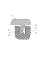
- the packing 3 includes a bent portion 32 and a base 33 as shown in FIG.
- the base 33 is formed in a substantially rectangular shape in cross section.
- the bent portion 32 protrudes from the lower end of the base portion 33.
- the bending portion 32 protrudes at a predetermined angle from an inward corner of the first housing 1 at the lower end of the base 33.
- the thickness of the connecting portion with the base portion 33 is set so that the bending portion 32 rotates in the bending direction when the bending portion 32 is pressed by the projecting portion 21 of the second housing 2 from above. It extends obliquely downward at its thickness. That is, the bending portion 32 protrudes in a tongue shape from the lower end of the base portion 33.
- the tip of the bent portion 32 is rounded so as to be able to slide well on the guide portion 16 and the bottom surface 18 of the groove portion 11 as described later.
- the notch part 34 is formed in the lower end of the base 33 so that the bending of the bending part 32 may not be inhibited.
- such a packing 3 is disposed in the groove 11, and the packing 3 is not yet pushed in by the projecting portion 21 of the second housing 2.
- the contact point P between the tip of the bending portion 32 and the bottom surface 18 of the groove 11 in the first housing 1 passes through the bending point (bottom of the necked portion) O of the bending portion 32 and protrudes in the second housing 2 It is disposed on a straight line N substantially orthogonal to the lower surface 23 of the portion 21 or on the bending direction side of the bent portion 32 from the straight line N.
- the groove portion 11 is formed in a substantially rectangular shape in cross section as shown in FIG.
- the width dimension of the groove part 11 is set so that the bending part 32 of the packing 3 can be favorably rotated in the bending direction, as shown in FIG.
- the depth of the groove portion 11 is such that when the packing 3 disposed in the groove portion 11 is pushed in by the protruding portion 21 of the second housing 2, the base portion 33 does not substantially compress, and the bent portion 32 It is set to rotate in the bending direction and to absorb the amount of depression of the protrusion 21.
- the bottom of the groove 11 has a guiding portion 16 for guiding the tip of the bent portion 32 of the packing 3 to a predetermined position.
- the guiding portion 16 is an inclined surface which is downwardly inclined continuously from the surface 17 on the inner side of the groove portion 11 to the bottom surface 18.
- the crossing portion C between the guiding portion 16 and the bottom surface 18 is the groove portion 11 with the packing 3 directed to the outside of the first housing 1 with the bending direction of the bending portion 32 in the packing 3 directed to the outside.
- the surface of the base 33 of the packing 3 is disposed inside, and the surface on the opposite side of the bending direction 32 of the bent portion 32 (in the present embodiment, the surface on the inner side of the first case 1 in the base 33) 35
- the tip of the bent portion 32 of the packing 3 is set at a position where it contacts the bottom surface 18 of the groove 11.
- the crossing portion C may be shifted to the outer side or the inner side of the first housing 1, as long as the bent portion 32 of the packing 3 can be guided in the original bending direction.
- the inclination angle of the guide portion 16 is set so that when the packing 3 is disposed in the groove portion 11, the tip end of the bent portion 32 of the packing 3 can be slipped and guided.
- the waterproof structure is realized as follows by using the first case 1, the second case 2, and the packing 3 of such a configuration.
- the packing 3 is disposed in the groove 11 of the first housing 1 in a state where the bending direction of the bending portion 32 in the packing 3 is directed to the outside of the first housing 1.
- the tip of the bent portion 32 of the packing 3 slides on the guiding portion 16 and is guided to the intersection C.
- the surface 35 of the base 33 of the packing 3 opposite to the bending direction of the bending portion 32 is in contact with the surface 17 of the groove portion 11 on the inner side of the first housing 1. That is, the packing 3 is positioned in a state where it is wound around the inward surface 17 of the first housing 1 in the groove 11.
- the packing 3 in this state is pushed in by the protruding portion 21 of the second housing 2, but in the state immediately before being pushed in, the intersection C where the tip of the bending portion 32 is disposed is the bending of the bending portion 32. It is disposed on a straight line N which passes through the point O and is substantially orthogonal to the lower surface 23 of the protrusion 21 of the second housing 2 or on the bending direction side of the bent portion 32 from the straight line N.
- the projecting portion 21 of the second housing 2 is disposed above the packing 3. Then, the packing 3 is pushed in by the protruding portion 21 of the second housing 2. Then, the packing 3 is in a state shown in FIG. 3 as the bent portion 32 is rotated in the bending direction without the base portion 33 being almost compressed. At this time, the contact point P between the tip of the bent portion 32 of the packing 3 and the bottom surface 18 of the groove 11 moves to the outer side of the first housing 1 and the surface of the bent portion 32 opposite to the bending direction (In the present embodiment, the inward surface of the first case 1 in the bending portion 32) contacts the guiding portion 16. Therefore, the packing 3 can be stabilized in the groove portion 11. Moreover, since the contact area between the packing 3 and the groove portion 11 can be gained, the waterproof performance can be improved. Finally, when the first housing 1 and the second housing 2 are joined by the bolt 4, a waterproof structure can be realized.
- Such a waterproof structure can guide the tip of the bent portion 32 in the packing 3 to a predetermined position (intersection C) on the bottom surface 18 of the groove portion 11 by the guiding portion 16. Therefore, the packing 3 can be easily positioned in the groove portion 11. Therefore, when the packing 3 is pushed in by the projecting portion 21 of the second housing 2, the bent portion 32 of the packing 3 does not rotate in an unintended direction. Therefore, damage to the packing 3 can be prevented, and the productivity of the electronic device excellent in waterproof performance can be improved.
- the packing 3 since the pushing amount of the protrusion part 21 of the 2nd housing
- the bending direction of the bending portion 32 is directed to the outside of the first housing 1. That is, the bending portion 32 does not easily rotate inward of the first housing 1. Therefore, even if water intrudes into the groove portion 11 from the outside of the first housing 1, the bent portion 32 plays a role of a valve and can prevent water infiltration.
- the bending direction of the bending portion 32 is directed to the outer side of the first housing 1, but the same can be applied substantially to the inward direction.
- the packing 3 is disposed in the groove 11 of the first housing 1 with the bending direction of the bending portion 32 of the packing 3 directed to the inward side of the first housing 1.
- the leading portion 16 of the groove 11 in the first housing 1 is such that the tip of the bent portion 32 in the packing 3 is the groove 11. It is formed to be disposed at a predetermined position on the bottom of the
- the guiding portion 16 is an inclined surface which is downwardly inclined continuously from the surface 19 on the outer side of the first housing 1 in the groove portion 11 to the bottom surface 18.
- the crossing portion C between the guiding portion 16 and the bottom surface 18 places the packing 3 in the groove portion 11 with the bent portion 32 of the packing 3 facing inward of the first housing 1.
- the tip of the bent portion 32 of the packing 3 is set at a position where it contacts the bottom surface 18 of the groove portion 11 when contacting the inward surface 17 of the groove 1.
- the crossing portion C may be shifted to the outer side or the inner side of the first housing 1, as long as the bent portion 32 of the packing 3 can be guided in the original bending direction. .
- the packing 3 when the packing 3 is disposed in the groove 11 of the first housing 1, the leading end of the bent portion 32 in the packing 3 is brought to a predetermined position (intersection C) in the bottom 18 of the groove 11 by the guiding portion 16. It can be induced. Then, as in the first embodiment, when the packing 3 is pushed in by the protruding portion 21 of the second housing 2, the packing 3 is such that the bent portion 32 is bent in the bending direction (arrow R direction ), And the state shown in FIG. 5 is obtained. At this time, the contact point P between the tip of the bent portion 32 of the packing 3 and the bottom surface 18 of the groove 11 moves to the inward side of the first housing 1 and the surface of the bent portion 32 opposite to the bending direction.
- the surface on the outer side of the first case 1 in the bending portion 32 contacts the guiding portion 16. Further, a surface (a surface on the outer side of the first casing 1 in the base 33 in the present embodiment) 35 of the base 33 of the packing 3 opposite to the bending direction of the bending portion 32 is a first in the groove 11. Contact the outer surface 19 of the housing 1.
- the bent portion 32 of the packing 3 when the bent portion 32 of the packing 3 is disposed toward the inward side of the first housing 1, the bent portion 32 easily rotates toward the inward side of the first housing 1. Therefore, if water intrudes into the groove 11 from the outside of the first housing 1, the bent portion 32 is pushed by the water and rotates in the bending direction, so that the water in the first housing 1 Results in allowing the infiltration of Therefore, it is preferable that the vicinity of the bending point O of the bending portion 32 be reinforced by the cladding 6 or the like. This can prevent the entry of water into the interior of the first housing 1.
- Embodiment 3 Although the tip of the bent portion 32 in the packing 3 of the first and second embodiments is rounded, it may be formed at an acute angle as shown in FIG. Thereby, the contact area of the tip of the bending portion 32 and the guiding portion 16 and the bottom surface 18 of the groove 11 can be reduced, and the friction when the tip of the bending portion 32 slides can be reduced.
- the protruding portion 21 of the second housing 2 is configured to push in the packing 3, but the protruding portion 21 is omitted and the packing 3 is removed by the lower surface 24 of the second housing 2. You may push it in.
- the height of the packing 3 is set higher than the height of the groove portion 11.
- the bending portion 32 rotates in the bending direction without the base 33 being almost compressed, and the packing It is set to absorb the amount of protrusion from the groove portion 11 of three.
- the height of the groove portion 11 can be lowered, so that the thickness of the waterproof structure and hence the thickness of the electronic device can be reduced.
- the present invention is not limited to the above embodiment, and can be appropriately modified without departing from the scope of the present invention.
- the tip of the bent portion 32 in order to reduce the sliding resistance of the tip of the bent portion 32 in the packing 3, the tip of the bent portion 32 has a rounded shape or an acute angle.
- the surface near the tip of the bent portion 32 may be subjected to emboss processing. Irregularities are formed in the vicinity of the tip of the bent portion 32 by emboss processing, and the friction between the groove portion 11 and the guide portion 16 and the bottom surface 18 can be reduced.
- a lubricant such as oil may be applied to the vicinity of the tip of the bent portion 32 and to the guide portion 16 and the bottom surface 18 of the groove portion 11.
- the vicinity of the tip of the bent portion 32 may be made of a material containing a lubricant.
- the packing 3 of the first embodiment is disposed upside down. That is, as shown in FIG. 8, the bent portion 32 of the packing 3 is obliquely upward in the state where it is not pushed in by the second housing 2, and the outward side of the first housing 1 (however, , May be the inner side)).
- the packing 3 is pushed by the lower surface 24 of the second housing 2 as in the fourth embodiment, as shown in FIG. Therefore, the height of the packing 3 is set to be higher than the height of the groove portion 110 of the first housing 1.
- the packing 3 may be pushed in by the projecting portion 21 of the second housing 2.
- the groove portion 110 of the first housing 1 includes a restraint portion 111 and a relief portion 112.
- the base 33 of the packing 3 is fitted into the restraint portion 111.
- the width dimension and the height of the restraint portion 111 are set so that the base portion 33 can be well restrained. Thereby, the packing 3 can be positioned only by fitting the packing 3 into the restraint portion 111 of the groove portion 110.
- the relief portion 112 is formed so that the bent portion 32 does not interfere with the groove portion 110 when the bent portion 32 of the packing 3 is rotated in the bending direction.
- the relief portion 112 in the present embodiment is obliquely upward from the outer surface 113 of the first case 1 in the restraint portion 111 and is the outer side of the first case 1. It is formed towards.
- the shape of the relief portion 112 is not particularly limited, and it may be formed so as not to interfere with the groove portion 11 when the bend portion 32 is rotated in the bending direction.
- the packing The base 33 of 3 is fitted. Then, when the second housing 2 is arranged to cover the opening of the first housing 1 from above, the bent portion 32 of the packing 3 is the lower surface 24 of the second housing 2 as shown in FIG. And is rotated in the direction of the arrow S, and the vicinity of the tip of the bent portion 32 escapes to the relief portion 112 of the groove portion 110. At this time, unlike the packing 3 of the first to fourth embodiments, the base 33 does not move in the vertical direction, so the deterioration of the packing 3 can be reduced.
- the width dimension of the restraint portion 111 of the groove portion 110 may be substantially equal to the width dimension of the base portion 33 of the packing 3, the width dimension of the groove portion 110 can be smaller than that of the groove portion 11 of the first to fourth embodiments. There is sex.
- the bent portion 32 of the packing 3 contacts the lower surface 24 of the second housing 2 and the base 33 of the packing 3 restrains the groove 110 As it is firmly fitted into the portion 111, the infiltration of water from the outside of the first housing 1 can be prevented.
- the claw portion 38 is laterally protruded from the base portion 33 of the packing 3 and the claw portion 38 is hooked on the hooking piece 120 formed on the first housing 1 to fix the packing 3
- the configuration may be Thus, a part of the rising portion 14 on the inner side of the first housing 1 can be omitted.
- the present invention can be suitably used, for example, for a waterproof structure of an electronic device such as a mobile phone, a smart phone, a PDA (Personal Digital Assistants), a tablet PC (Personal Computer) and the like.
- an electronic device such as a mobile phone, a smart phone, a PDA (Personal Digital Assistants), a tablet PC (Personal Computer) and the like.
Landscapes
- Engineering & Computer Science (AREA)
- General Engineering & Computer Science (AREA)
- Mechanical Engineering (AREA)
- Physics & Mathematics (AREA)
- Geometry (AREA)
- Casings For Electric Apparatus (AREA)
- Telephone Set Structure (AREA)
- Gasket Seals (AREA)
Abstract
パッキンの位置決めを容易に行うことができる防水構造を提供する。本発明の一形態に係る防水構造は、溝部(11)が形成される第1の筐体(1)と、溝部(11)に配置されるパッキン(3)と、パッキン(3)を押し込み、第1の筐体(1)とで密閉空間を形成する第2の筐体(2)と、を備え、パッキン(3)は、屈曲部(32)を有し、第2の筐体(2)で押し込まれていない状態で、屈曲部(32)の先端と第1の筐体(1)の溝部底面(18)との接触点(P)が、屈曲部(32)の屈曲点(O)を通り第2の筐体(2)におけるパッキン(3)との接触面と略直交する直線(N)より、屈曲部(32)の屈曲方向側に配置され、溝部(11)は、屈曲部(32)の先端を第1の筐体(1)の溝部底面(18)の所定の位置に誘導する誘導部(16)を有する。
Description
本発明は、防水構造及びその形成方法に関し、特に第1の筐体と第2の筐体とで密閉空間を形成するために用いられる防水構造及びその形成方法に関する。
第1の筐体と第2の筐体とで密閉空間を形成する場合、図1に示すように、第1の筐体1と第2の筐体2との間にパッキン3を配置することが一般的である。つまり、第1の筐体1に形成された溝部11内にパッキン3が配置される。そして、当該パッキン3を介して第1の筐体1と第2の筐体2とがボルト4で接合される。
このような場合、図11に示すように、パッキン3は第2の筐体2に形成された突出部21で押し込まれる。なお、図11では、第2の筐体2の突出部21で押し込まれていない状態でのパッキン3を示している。そのため、図11の破線は突出部21の仮想線である。
上述のように、パッキン3が圧縮された際に、パッキン3が大きな反力を発現すると、第2の筐体2が浮き上がる可能性がある。そのため、パッキン3に突出部31を形成することで、図12に示すように、パッキン3が第2の筐体2の突出部21で押し込まれても、当該突出部31部分が変形して大きな反力が発現しないように工夫している。
しかし、パッキン3に突出部31を形成しても、パッキン3は大きな反力を発現する。そのため、図11及び図12に示すように、例えば第1の筐体1に爪部12を形成している。また、第2の筐体2に爪部25を形成している。そして、第1の筐体1の爪部12と第2の筐体2の爪部25とを噛み合わせることで、当該反力に対抗して第2の筐体2の浮き上がりを防いでいる。このような構成では、相互に爪部を形成するため、筐体の大型化を招く。
ところで、特許文献1には、断面形状が上下両端に同一方向に設けられた突出部と、略中央部に当該突出部と同一方向に向けて設けられた中央突出部とを備えるガスケットを用いて、第1の筐体と第2の筐体とで密閉空間を形成する技術が開示されている。
また、特許文献2には、断面形状が略楕円形状の本体部から斜め上方に延びるリップ部を備えるガスケットを用いて、第1の筐体と第2の筐体とで密閉空間を形成する技術が開示されている。
また、特許文献2には、断面形状が略楕円形状の本体部から斜め上方に延びるリップ部を備えるガスケットを用いて、第1の筐体と第2の筐体とで密閉空間を形成する技術が開示されている。
特許文献1及び2の技術は、第1の筐体の溝部に配置されたガスケットを第2の筐体で押し込む際の、当該ガスケットの位置を容易に定めることができない。そのため、第2の筐体の押し込みによって、突出部やリップ部が意図しない方向に曲がる可能性がある。
本発明の目的は、上述した課題を解決する防水構造及びその形成方法を提供することにある。
本発明の一形態に係る防水構造は、溝部が形成される第1の筐体と、前記溝部に配置されるパッキンと、前記パッキンを押し込み、前記第1の筐体とで密閉空間を形成する第2の筐体と、を備え、前記パッキンは、屈曲部を有し、前記第2の筐体で押し込まれていない状態で、前記屈曲部の先端と前記第1の筐体の溝部底面との接触点が、前記屈曲部の屈曲点を通り前記第2の筐体における前記パッキンとの接触面と略直交する直線より、前記屈曲部の屈曲方向側に配置され、前記溝部は、前記屈曲部の先端を前記第1の筐体の溝部底面の所定の位置に誘導する誘導部を有する。
本発明の一形態に係る防水構造の形成方法は、第1の筐体に形成された溝部にパッキンを配置し、前記パッキンの屈曲部の先端を、前記第1の筐体の誘導部によって当該第1の筐体の溝部底面の所定の位置に誘導して、前記パッキンの屈曲部の先端と前記第1の筐体の溝部底面との接触点を、前記屈曲部の屈曲点を通り前記第2の筐体における前記パッキンとの接触面と略直交する直線より、前記屈曲部の屈曲方向側に配置し、前記第2の筐体で前記パッキンを押し込み、前記第1の筐体とで密閉空間を形成する。
本発明によれば、パッキンの位置決めを容易に行うことができる防水構造及びその形成方法を提供することができる。
本発明の実施の形態に係る防水構造及びその形成方法について説明する。但し、本発明が以下の実施の形態に限定される訳ではない。また、説明を明確にするため、以下の記載及び図面は、適宜、簡略化されている。また、以下の説明の上下方向は、図面に基づいており、使用形態によって変化する。
<実施の形態1>
実施の形態1の防水構造及びその形成方法を説明する。本実施の形態の防水構造及びその形成方法は、例えば携帯電話、スマートフォン、PDA(Personal Digital Assistants)、タブレットPC(Personal Computer)等の電子機器の防水構造に好適に用いることができる。
実施の形態1の防水構造及びその形成方法を説明する。本実施の形態の防水構造及びその形成方法は、例えば携帯電話、スマートフォン、PDA(Personal Digital Assistants)、タブレットPC(Personal Computer)等の電子機器の防水構造に好適に用いることができる。
この防水構造は、一般的な防水構造と同様の構成要素を備えている。つまり、防水構造は、図1に示すように、第1の筐体1、第2の筐体2、パッキン3を備えている。
第1の筐体1は、上面(但し、下面でも良い。)に開口部分を有する。第1の筐体1は、例えば内部に電子機器の機能を実現する電子基板や表示装置等を搭載可能な空間13を有する。この空間13を取り囲むように、立ち上がり部14が形成されている。
第1の筐体1は、上面(但し、下面でも良い。)に開口部分を有する。第1の筐体1は、例えば内部に電子機器の機能を実現する電子基板や表示装置等を搭載可能な空間13を有する。この空間13を取り囲むように、立ち上がり部14が形成されている。
立ち上がり部14の上面15は、図2に示すように、平面に形成されている。立ち上がり部14は、パッキン3を嵌め込むための溝部11を形成するのに十分な幅寸法を有する。溝部11は、立ち上がり部14に形成されている。溝部11は、第1の筐体1の外縁を囲むように、平面から見て環状に形成されている。なお、溝部11の具体的な形状については、後述する。立ち上がり部14の外方における第1の筐体1の四隅部分には、ボルト孔5が形成されている。
第2の筐体2は、第1の筐体1とで密閉空間を形成するために、第1の筐体1の開口部分を覆う蓋部材である。第2の筐体2は、図2に示すように、第1の筐体1を覆うように配置された際に、少なくとも第1の筐体1の立ち上がり部14の上面15と接触する領域22が、平面に形成されている。そのため、図3に示すように、第2の筐体2で第1の筐体1を覆った際に、第1の筐体1の立ち上がり部14の上面15と第2の筐体2の領域22とは、面接触する。
第2の筐体2は、第1の筐体1と略等しい平面形状に形成されている。第2の筐体2は、図2に示すように、第1の筐体1の溝部11と対応する位置に、パッキン3を押し込む突出部21が形成されている。突出部21も、平面から見て環状に形成されている。そして、突出部21の下面23は、領域22と略平行面を形成する。
突出部21の幅寸法は、突出部21を第1の筐体1の溝部11内に挿入することができるように、設定されている。また、突出部21の高さは、詳細は後述するが、図2の状態から図3の状態に、パッキン3の屈曲部32を当該屈曲部32の屈曲方向(矢印Q方向(第1の筐体1の外方側))に屈曲させることができるように、設定されている。
パッキン3は、図1及び図2等に示すように、第1の筐体1の溝部11内に配置される。つまり、パッキン3は、第1の筐体1の溝部11の形状に倣って、環状に形成されている。パッキン3は、例えばゴム等の弾性を有する樹脂成形品である。パッキン3は、図2に示すように、屈曲部32、基部33を備えている。
基部33は、断面視が略矩形状に形成されている。基部33の下端から屈曲部32が突出している。詳細には、屈曲部32は、基部33の下端における第1の筐体1の内方側の角部から所定の角度で突出する。屈曲部32は、上方から第2の筐体2の突出部21で押し込まれた際に、当該屈曲部32が屈曲方向に回転するように、基部33との連結部分の厚さが設定されており、その厚さで斜め下方に向かって延在する。つまり、屈曲部32は、基部33の下端から舌状に突出している。
屈曲部32の先端部は、後述するように溝部11の誘導部16及び底面18上を良好に摺動することができるように、丸みを帯びた形状とされている。なお、基部33の下端には、屈曲部32の屈曲を阻害しないように、切り欠き部34が形成されている。
このようなパッキン3は、図2に示すように、パッキン3が溝部11内に配置され、且つパッキン3が第2の筐体2の突出部21で未だに押し込まれていない状態で、パッキン3における屈曲部32の先端と第1の筐体1における溝部11の底面18との接触点Pは、屈曲部32の屈曲点(くびれている部分の底部)Oを通り第2の筐体2における突出部21の下面23と略直交する直線N上、又は当該直線Nより屈曲部32の屈曲方向側に配置される。
ここで、第1の筐体1の溝部11の形状を説明する。溝部11は、図2に示すように、断面視が略矩形状に形成されている。溝部11の幅寸法は、図3に示すように、パッキン3の屈曲部32が良好に屈曲方向に回転することができるように、設定されている。また、溝部11の深さは、当該溝部11内に配置されたパッキン3が第2の筐体2の突出部21で押し込まれた際に、基部33が略圧縮せずに、屈曲部32が屈曲方向に回転して、当該突出部21の押し込み量を吸収するように、設定されている。この溝部11の底部は、パッキン3における屈曲部32の先端を所定の位置に誘導する誘導部16を有する。
誘導部16は、溝部11における内方側の面17から底面18まで連続して下方に向かって傾斜する傾斜面である。誘導部16と底面18との交差部Cは、図2に示すように、パッキン3における屈曲部32の屈曲方向を第1の筐体1の外方に向けた状態で当該パッキン3を溝部11内に配置し、パッキン3の基部33における屈曲部32の屈曲方向と逆側の面(本実施の形態では、基部33における第1の筐体1の内方側の面)35を溝部11の内方側の面17に接触させた際に、パッキン3における屈曲部32の先端が溝部11の底面18に接触する位置に設定される。但し、交差部Cは、第1の筐体1の外方側又は内方側にずれていても良く、要するにパッキン3における屈曲部32が本来の屈曲方向に向かうように誘導することができれば良い。誘導部16の傾斜角度は、パッキン3を溝部11内に配置した際に、パッキン3における屈曲部32の先端を滑らせて誘導することができるように、設定されている。
このような構成の第1の筐体1、第2の筐体2、パッキン3を用いて、以下のように防水構造を実現する。
図2に示すように、パッキン3における屈曲部32の屈曲方向を第1の筐体1の外方に向けた状態で、パッキン3を第1の筐体1の溝部11内に配置する。このとき、パッキン3の屈曲部32の先端は誘導部16上を摺動して、交差部Cに誘導される。また、パッキン3の基部33における屈曲部32の屈曲方向と逆側の面35が溝部11における第1の筐体1の内方側の面17に接触した状態となる。つまり、パッキン3が溝部11における第1の筐体1の内方側の面17に凭れた状態で位置決めされる。
図2に示すように、パッキン3における屈曲部32の屈曲方向を第1の筐体1の外方に向けた状態で、パッキン3を第1の筐体1の溝部11内に配置する。このとき、パッキン3の屈曲部32の先端は誘導部16上を摺動して、交差部Cに誘導される。また、パッキン3の基部33における屈曲部32の屈曲方向と逆側の面35が溝部11における第1の筐体1の内方側の面17に接触した状態となる。つまり、パッキン3が溝部11における第1の筐体1の内方側の面17に凭れた状態で位置決めされる。
この状態のパッキン3を第2の筐体2の突出部21で押し込むことになるが、押し込まれる直前の状態で、屈曲部32の先端が配置されている交差点Cは、当該屈曲部32の屈曲点Oを通り第2の筐体2における突出部21の下面23と略直交する直線N上、又は当該直線Nより屈曲部32の屈曲方向側に配置される。
パッキン3の上方に第2の筐体2の突出部21を配置する。そして、第2の筐体2の突出部21でパッキン3を押し込む。すると、パッキン3は、基部33が殆ど圧縮されずに、屈曲部32が屈曲方向に回転して、図3に示す状態になる。このとき、パッキン3における屈曲部32の先端と溝部11の底面18との接触点Pは、第1の筐体1の外方側に移動すると共に、屈曲部32における屈曲方向と逆側の面(本実施の形態では、屈曲部32における第1の筐体1の内方側の面)36が誘導部16に接触する。そのため、パッキン3を溝部11内で安定させることができる。しかも、パッキン3と溝部11との接触面積を稼ぐことができるので、防水性能を向上させることができる。
最後に、第1の筐体1と第2の筐体2とをボルト4で接合すると、防水構造を実現することができる。
最後に、第1の筐体1と第2の筐体2とをボルト4で接合すると、防水構造を実現することができる。
このような防水構造は、パッキン3における屈曲部32の先端を、誘導部16によって溝部11の底面18における所定の位置(交差点C)に誘導することができる。そのため、溝部11内でのパッキン3の位置決めを容易に行うことができる。したがって、パッキン3を第2の筐体2の突出部21で押し込んだ際に、パッキン3の屈曲部32が意図しない方向に回転することがない。よって、パッキン3の損傷を防ぐことができ、防水性能に優れた電子機器の生産性を向上させることができる。
しかも、パッキン3の屈曲部32が回転することで、第2の筐体2の突出部21の押し込み量を吸収するので、パッキン3は殆ど反力を発現しない。そのため、第1の筐体1及び第2の筐体2は、パッキン3の反力に対抗する必要が殆ど無いので、第1の筐体1及び第2の筐体2を小型化、簡素化することができる。
ちなみに、本実施の形態のパッキン3は、屈曲部32の屈曲方向を第1の筐体1の外方に向けている。つまり、屈曲部32は、第1の筐体1の内方に向かって回転し難い。そのため、万一に、第1の筐体1の外部から溝部11内に水が浸入しても、屈曲部32が弁の役割を果たして、水の浸入を防ぐことができる。
<実施の形態2>
実施の形態1のパッキン3は、屈曲部32の屈曲方向を第1の筐体1の外方に向けたが、内方に向けても略同様に実施することができる。
実施の形態1のパッキン3は、屈曲部32の屈曲方向を第1の筐体1の外方に向けたが、内方に向けても略同様に実施することができる。
つまり、図4に示すように、パッキン3における屈曲部32の屈曲方向を第1の筐体1の内方側に向けた状態で、パッキン3を第1の筐体1の溝部11内に配置する。このときも、第1の筐体1における溝部11の誘導部16は、パッキン3を第1の筐体1の溝部11内に配置した際に、パッキン3における屈曲部32の先端が当該溝部11の底面における所定の位置に配置されるように形成される。
詳細には、誘導部16は、溝部11における第1の筐体1の外方側の面19から底面18まで連続して下方に向かって傾斜する傾斜面である。誘導部16と底面18との交差部Cは、図4に示すように、パッキン3の屈曲部32を第1の筐体1の内方に向けた状態で当該パッキン3を溝部11内に配置し、パッキン3の基部33における屈曲部32の屈曲方向側の面(本実施の形態では、基部33における第1の筐体1の内方側の面)37を溝部11における第1の筐体1の内方側の面17に接触させた際に、パッキン3における屈曲部32の先端が溝部11の底面18に接触する位置に設定される。但し、交差部Cは、第1の筐体1の外方側又は内方側にずれていても良く、要するにパッキン3における屈曲部32が本来の屈曲方向に向かうように誘導することができれば良い。
これにより、パッキン3を第1の筐体1の溝部11内に配置した際に、パッキン3における屈曲部32の先端を、誘導部16によって溝部11の底面18における所定の位置(交差点C)に誘導することができる。そして、実施の形態1と同様に、パッキン3を第2の筐体2の突出部21で押し込むと、パッキン3は、基部33が殆ど圧縮されずに、屈曲部32が屈曲方向(矢印R方向)に回転して、図5に示す状態になる。このとき、パッキン3における屈曲部32の先端と溝部11の底面18との接触点Pは、第1の筐体1の内方側に移動すると共に、屈曲部32における屈曲方向と逆側の面(本実施の形態では、屈曲部32における第1の筐体1の外方側の面)36が誘導部16に接触する。また、パッキン3の基部33における屈曲部32の屈曲方向と逆側の面(本実施の形態では、基部33における第1の筐体1の外方側の面)35が溝部11における第1の筐体1の外方側の面19に接触する。
ちなみに、パッキン3の屈曲部32を第1の筐体1の内方側に向けて配置した場合、屈曲部32は第1の筐体1の内方側に向かって回転し易い。そのため、万一に、第1の筐体1の外部から溝部11内に水が浸入すると、屈曲部32が水に押されて屈曲方向に回転して、第1の筐体1の内部に水の浸入を許す結果となる。そのため、屈曲部32の屈曲点O近傍を肉盛り6等によって補強していることが好ましい。これにより、第1の筐体1の内部への水の浸入を防ぐことができる。
<実施の形態3>
実施の形態1及び2のパッキン3における屈曲部32の先端は、丸みをおびた形状とされているが、図6に示すように、鋭角に形成されていても良い。これにより、屈曲部32の先端と溝部11の誘導部16及び底面18との接触面積を低減することができ、屈曲部32の先端が摺動する際の摩擦を低減することができる。
実施の形態1及び2のパッキン3における屈曲部32の先端は、丸みをおびた形状とされているが、図6に示すように、鋭角に形成されていても良い。これにより、屈曲部32の先端と溝部11の誘導部16及び底面18との接触面積を低減することができ、屈曲部32の先端が摺動する際の摩擦を低減することができる。
<実施の形態4>
実施の形態1乃至3では、第2の筐体2の突出部21がパッキン3を押し込む構成とされているが、突出部21を省略して第2の筐体2の下面24でパッキン3を押し込んでも良い。このとき、パッキン3の高さは、溝部11の高さより高く設定される。そして、パッキン3は、第2の筐体2の下面24で押し込まれた際に、図7に示すように、基部33が殆ど圧縮することなく、屈曲部32が屈曲方向に回転して、パッキン3の溝部11からの突出量を吸収するように、設定される。
このような構成により、溝部11の高さを低くすることができるので、防水構造の厚さ、ひいては電子機器の厚さを薄くすることができる。
実施の形態1乃至3では、第2の筐体2の突出部21がパッキン3を押し込む構成とされているが、突出部21を省略して第2の筐体2の下面24でパッキン3を押し込んでも良い。このとき、パッキン3の高さは、溝部11の高さより高く設定される。そして、パッキン3は、第2の筐体2の下面24で押し込まれた際に、図7に示すように、基部33が殆ど圧縮することなく、屈曲部32が屈曲方向に回転して、パッキン3の溝部11からの突出量を吸収するように、設定される。
このような構成により、溝部11の高さを低くすることができるので、防水構造の厚さ、ひいては電子機器の厚さを薄くすることができる。
本発明は上記実施の形態に限られたものではなく、趣旨を逸脱しない範囲で適宜変更することが可能である。
上記実施の形態では、パッキン3における屈曲部32の先端の摺動抵抗を低減するために、当該屈曲部32の先端を、丸みをおびた形状としたり、鋭角に形成したりしたが、この限りでない。つまり、屈曲部32の先端近傍にシボ処理を施しても良い。シボ処理によって屈曲部32の先端近傍に凹凸が形成され、溝部11の誘導部16及び底面18との摩擦を低減することができる。
また、屈曲部32の先端近傍や溝部11の誘導部16及び底面18に油等の潤滑剤を塗布しても良い。さらに屈曲部32の先端近傍を潤滑剤が含有された材質で構成しても良い。
上記実施の形態では、パッキン3における屈曲部32の先端の摺動抵抗を低減するために、当該屈曲部32の先端を、丸みをおびた形状としたり、鋭角に形成したりしたが、この限りでない。つまり、屈曲部32の先端近傍にシボ処理を施しても良い。シボ処理によって屈曲部32の先端近傍に凹凸が形成され、溝部11の誘導部16及び底面18との摩擦を低減することができる。
また、屈曲部32の先端近傍や溝部11の誘導部16及び底面18に油等の潤滑剤を塗布しても良い。さらに屈曲部32の先端近傍を潤滑剤が含有された材質で構成しても良い。
ちなみに、上述のパッキン3を用いて、以下に示す形態で防水構造を実現することも可能である。
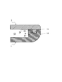
図8及び図9に示す防水構造は、実施の形態1のパッキン3を上下逆に配置している。つまり、パッキン3の屈曲部32は、図8に示すように、第2の筐体2で押し込まれていない状態で、斜め上方であって、且つ第1の筐体1の外方側(但し、内方側でも良い。)に向かって配置されている。このパッキン3は、図9に示すように、実施の形態4と同様に第2の筐体2の下面24で押し込まれる。そのため、パッキン3の高さは、第1の筐体1の溝部110の高さより高く設定されている。但し、実施の形態1及び2のパッキン3のように、パッキン3を第2の筐体2の突出部21で押し込んでも良い。
図8及び図9に示す防水構造は、実施の形態1のパッキン3を上下逆に配置している。つまり、パッキン3の屈曲部32は、図8に示すように、第2の筐体2で押し込まれていない状態で、斜め上方であって、且つ第1の筐体1の外方側(但し、内方側でも良い。)に向かって配置されている。このパッキン3は、図9に示すように、実施の形態4と同様に第2の筐体2の下面24で押し込まれる。そのため、パッキン3の高さは、第1の筐体1の溝部110の高さより高く設定されている。但し、実施の形態1及び2のパッキン3のように、パッキン3を第2の筐体2の突出部21で押し込んでも良い。
第1の筐体1の溝部110は、拘束部111、逃げ部112を備えている。拘束部111には、パッキン3の基部33が嵌め込まれる。拘束部111の幅寸法及び高さは、基部33を良好に拘束することができるように、設定されている。これにより、パッキン3を溝部110の拘束部111に嵌め込むだけで、パッキン3を位置決めすることができる。
逃げ部112は、パッキン3の屈曲部32が屈曲方向に回転した際に当該屈曲部32が溝部110に干渉しないように、形成されている。本実施の形態の逃げ部112は、拘束部111における第1の筐体1の外方側の面113から連続するように、斜め上方であって、且つ第1の筐体1の外方側に向かって形成されている。但し、逃げ部112の形状は、特に限定されず、要するに屈曲部32が屈曲方向に回転した際に当該屈曲部32が溝部11に干渉しないように形成されていれば良い。
このような第1の筐体1における溝部110の拘束部111に、パッキン3の屈曲部32を斜め上方であって、且つ第1の筐体1の外方側に向けた状態で、当該パッキン3の基部33を嵌め込む。そして、上方から第1の筐体1の開口部分を覆うように第2の筐体2を配置すると、図9に示すように、パッキン3の屈曲部32が第2の筐体2の下面24に押し込まれて矢印S方向に回転し、当該屈曲部32の先端近傍が溝部110の逃げ部112に逃げる。このとき、実施の形態1乃至4のパッキン3と異なり、基部33が上下方向に移動しないので、パッキン3の劣化を低減することができる。しかも、溝部110の拘束部111の幅寸法は、パッキン3の基部33と略等しい幅寸法で良いので、実施の形態1乃至4の溝部11よりも溝部110の幅寸法を小さくすることができる可能性がある。
このようにパッキン3を上下逆に用いても、図9に示すようにパッキン3の屈曲部32が第2の筐体2の下面24に接触し、しかもパッキン3の基部33が溝部110の拘束部111にしっかりと嵌め込まれるので、第1の筐体1の外方からの水の浸入を防止することができる。
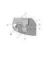
ちなみに、図10に示すように、パッキン3の基部33から爪部38を側方に突出させ、当該爪部38を第1の筐体1に形成した引っ掛け片120に引っ掛けて、パッキン3を固定する構成でも良い。これにより、立ち上がり部14における第1の筐体1の内方側の一部分を省略することができる。
この出願は、2010年12月21日に出願された日本出願特願2010-284625を基礎とする優先権を主張し、その開示の全てをここに取り込む。
本発明は、例えば携帯電話、スマートフォン、PDA(Personal Digital Assistants)、タブレットPC(Personal Computer)等の電子機器の防水構造に好適に用いることができる。
1 第1の筐体
2 第2の筐体
3 パッキン
4 ボルト
5 ボルト孔
6 肉盛り
11 溝部
12 第1の筐体の爪部
13 空間
14 立ち上がり部
15 立ち上がり部の上面
16 誘導部
17 溝部の内方側の面
18 溝部の底面
19 溝部の外方側の面
21 突出部
22 第2の筐体における第1の筐体の立ち上がり部と接触する領域
23 突出部の下面
24 第2の筐体の下面
25 第2の筐体の爪部
31 パッキンの突出部
32 パッキンの屈曲部
33 パッキンの基部
34 基部の切り欠き部
35 基部における屈曲部の屈曲方向と逆側の面
36 屈曲部における屈曲方向と逆側の面
37 基部における屈曲部の屈曲方向側の面
38 パッキンの爪部
110 溝部
111 拘束部
112 逃げ部
113 拘束部における第1の筐体に外方側の面
120 引っ掛け片
Claims (10)
- 溝部が形成される第1の筐体と、
前記溝部に配置されるパッキンと、
前記パッキンを押し込み、前記第1の筐体とで密閉空間を形成する第2の筐体と、を備え、
前記パッキンは、屈曲部を有し、前記第2の筐体で押し込まれていない状態で、前記屈曲部の先端と前記第1の筐体の溝部底面との接触点が、前記屈曲部の屈曲点を通り前記第2の筐体における前記パッキンとの接触面と略直交する直線より、前記屈曲部の屈曲方向側に配置され、
前記溝部は、前記屈曲部の先端を前記第1の筐体の溝部底面の所定の位置に誘導する誘導部を有する防水構造。 - 前記誘導部は傾斜面であって、前記パッキンが前記第2の筐体に押し込まれている状態で、前記屈曲部における屈曲方向と逆側の面が接触する請求項1に記載の防水構造。
- 前記屈曲部の屈曲方向は、前記第1の筐体の外方に向かっている請求項1又は2に記載の防水構造。
- 前記屈曲部の屈曲方向は、前記第1の筐体の内方に向かっている請求項1又は2に記載の防水構造。
- 前記屈曲部の屈曲点近傍は、補強されている請求項4に記載の防水構造。
- 前記屈曲部の先端は、鋭角に形成されている請求項1乃至5のいずれか1項に記載の防水構造。
- 前記屈曲部の先端近傍は、シボ処理されている請求項1乃至6のいずれか1項に記載の防水構造。
- 前記屈曲部の先端近傍には、潤滑剤が塗布されている請求項1乃至7のいずれか1項に記載の防水構造。
- 前記溝部の底面には、潤滑剤が塗布されている請求項1乃至8のいずれか1項に記載の防水構造。
- 第1の筐体に形成された溝部にパッキンを配置し、
前記パッキンの屈曲部の先端を、前記第1の筐体の誘導部によって当該第1の筐体の溝部底面の所定の位置に誘導して、前記パッキンの屈曲部の先端と前記第1の筐体の溝部底面との接触点を、前記屈曲部の屈曲点を通り前記第2の筐体における前記パッキンとの接触面と略直交する直線より、前記屈曲部の屈曲方向側に配置し、
前記第2の筐体で前記パッキンを押し込み、前記第1の筐体とで密閉空間を形成する防水構造の形成方法。
Priority Applications (4)
| Application Number | Priority Date | Filing Date | Title |
|---|---|---|---|
| EP11850051.1A EP2657579A4 (en) | 2010-12-21 | 2011-11-02 | WATERTIGHT STRUCTURE AND METHOD OF FORMING SAME |
| CN201180061467.1A CN103370563B (zh) | 2010-12-21 | 2011-11-02 | 防水结构、形成该防水结构的方法以及端子 |
| JP2012549603A JP5888241B2 (ja) | 2010-12-21 | 2011-11-02 | 防水構造及びその形成方法、端末 |
| US13/992,430 US9248944B2 (en) | 2010-12-21 | 2011-11-02 | Waterproof structure, method of forming the same, and terminal |
Applications Claiming Priority (2)
| Application Number | Priority Date | Filing Date | Title |
|---|---|---|---|
| JP2010284625 | 2010-12-21 | ||
| JP2010-284625 | 2010-12-21 |
Publications (1)
| Publication Number | Publication Date |
|---|---|
| WO2012086115A1 true WO2012086115A1 (ja) | 2012-06-28 |
Family
ID=46313410
Family Applications (1)
| Application Number | Title | Priority Date | Filing Date |
|---|---|---|---|
| PCT/JP2011/006156 Ceased WO2012086115A1 (ja) | 2010-12-21 | 2011-11-02 | 防水構造及びその形成方法 |
Country Status (5)
| Country | Link |
|---|---|
| US (1) | US9248944B2 (ja) |
| EP (1) | EP2657579A4 (ja) |
| JP (1) | JP5888241B2 (ja) |
| CN (1) | CN103370563B (ja) |
| WO (1) | WO2012086115A1 (ja) |
Cited By (5)
| Publication number | Priority date | Publication date | Assignee | Title |
|---|---|---|---|---|
| JP2014173370A (ja) * | 2013-03-12 | 2014-09-22 | Daido Signal Co Ltd | 屋外機器の防水構造 |
| WO2014128137A3 (en) * | 2013-02-19 | 2014-12-31 | Tyco Electronics Raychem Bvba | Sealing interface for a telecommunications enclosure |
| CN104570675A (zh) * | 2013-10-22 | 2015-04-29 | 富士施乐株式会社 | 密封部件、收容部件及图像形成装置 |
| CN108234702A (zh) * | 2018-01-18 | 2018-06-29 | 广东欧珀移动通信有限公司 | 显示屏组件及电子设备 |
| JP2020104179A (ja) * | 2018-12-26 | 2020-07-09 | ファナック株式会社 | ロボットのシール構造およびロボット |
Families Citing this family (20)
| Publication number | Priority date | Publication date | Assignee | Title |
|---|---|---|---|---|
| CN105579750B (zh) * | 2013-09-27 | 2018-12-25 | 大陆汽车系统公司 | 用于装置的密封结构及防流体进入的方法 |
| CN103879646B (zh) * | 2014-04-18 | 2016-01-20 | 江苏固得塑胶有限公司 | 一种塑料桶 |
| CN104019235A (zh) * | 2014-05-21 | 2014-09-03 | 北京特泽热力工程设计有限责任公司 | 楔形硫化硅橡胶胶圈 |
| TWI516184B (zh) * | 2014-08-25 | 2016-01-01 | 緯創資通股份有限公司 | 保護結構及其電子裝置 |
| KR20160046612A (ko) * | 2014-10-21 | 2016-04-29 | 삼성전자주식회사 | 내부에 전기 부품을 수납하는 케이스 및 이를 채용한 전자 기기 |
| EP3032929B1 (en) * | 2014-12-10 | 2018-08-22 | Continental Automotive GmbH | Housing for electronic control unit |
| KR102506256B1 (ko) | 2015-08-31 | 2023-03-07 | 삼성전자 주식회사 | 방수구조를 가지는 전자 장치 |
| US10132410B2 (en) * | 2016-03-22 | 2018-11-20 | Tower Mfg Corp | Sealing assembly for mating an electrical device enclosure |
| US9844157B1 (en) * | 2016-06-14 | 2017-12-12 | Apple Inc. | Gasket for an electronic device |
| DE102016215154B4 (de) * | 2016-08-15 | 2025-02-20 | Festo Se & Co. Kg | Abdichtungssystem |
| CN107889406A (zh) * | 2016-09-30 | 2018-04-06 | 光宝电子(广州)有限公司 | 壳体及其胶条结构与阻水边框 |
| US10634252B2 (en) * | 2017-03-15 | 2020-04-28 | Tower Manufacturing Company | Dual gasket retainers for mating electrical device enclosures |
| US10539236B2 (en) * | 2017-03-15 | 2020-01-21 | Tower Manufacturing Corporation | Gasket retainer for mating an electrical device enclosure |
| CN108882581B (zh) * | 2018-07-03 | 2020-10-13 | 芜湖威灵数码科技有限公司 | 一种用于大型仪器仪表的防水装置 |
| CN111075926B (zh) * | 2018-10-19 | 2021-11-12 | 中兴通讯股份有限公司 | 密封件、电子产品以及电子产品的密封方法 |
| EP4032158A4 (en) * | 2019-09-20 | 2023-10-11 | CommScope Technologies LLC | TELECOMMUNICATIONS HOUSING WITH CONTAINER STRUCTURES FOR O-RINGS |
| DE112020005443B4 (de) * | 2020-01-08 | 2024-04-11 | Mitsubishi Electric Corporation | Industriegerät |
| JP7616385B2 (ja) * | 2022-02-28 | 2025-01-17 | 株式会社パトライト | 電子機器、及びガスケット |
| KR102907503B1 (ko) * | 2023-01-03 | 2026-01-02 | 엘지전자 주식회사 | 세탁물 처리기기 |
| TWI870796B (zh) * | 2023-03-10 | 2025-01-21 | 英業達股份有限公司 | 密封防水結構 |
Citations (6)
| Publication number | Priority date | Publication date | Assignee | Title |
|---|---|---|---|---|
| JPH10154750A (ja) | 1997-10-24 | 1998-06-09 | Komatsu Electron Metals Co Ltd | 半導体ウェーハ包装容器用ガスケット |
| JP2005127437A (ja) * | 2003-10-24 | 2005-05-19 | Miraial Kk | シール部材 |
| JP2006220229A (ja) | 2005-02-10 | 2006-08-24 | Nippon Valqua Ind Ltd | あり溝用シール材 |
| JP2008248899A (ja) * | 2007-03-29 | 2008-10-16 | Nhk Spring Co Ltd | シール部位のシール構造 |
| JP2008249139A (ja) * | 2007-03-02 | 2008-10-16 | Nok Corp | 電子機器の防水構造 |
| JP2010284625A (ja) | 2009-06-15 | 2010-12-24 | Mitsubishi Electric Corp | 静電霧化装置及び空気調和機 |
Family Cites Families (16)
| Publication number | Priority date | Publication date | Assignee | Title |
|---|---|---|---|---|
| DE821746C (de) * | 1950-05-06 | 1951-11-19 | Berkefeld Filter Ges | Dichtung fuer Behaelter u. dgl. |
| US2910209A (en) * | 1953-08-18 | 1959-10-27 | Walter K Nelson | Sealer strips |
| US3106406A (en) * | 1960-06-29 | 1963-10-08 | Illinois Milling Inc | Oil seal |
| US4156532A (en) * | 1975-12-28 | 1979-05-29 | Toyota Jidosha Kogyo Kabushiki Kaisha | Sealing device for an automobile disk brake |
| US4298204A (en) * | 1980-01-21 | 1981-11-03 | Black & Decker Inc. | Seal |
| US5160474A (en) | 1990-12-21 | 1992-11-03 | Cadillac Rubber & Plastics, Inc. | Overmolded gasket, heat exchanger tank incorporating the same and method for making the same |
| DE10017221A1 (de) * | 2000-04-06 | 2001-10-11 | Ralph Peter Hegler | Dichtungs-Ring für Verbindung zwischen Spitzende eines Wellrohres und Rohr-Muffe mit glatter Innenwand |
| JP2004286987A (ja) * | 2003-03-20 | 2004-10-14 | Olympus Corp | 防水構造 |
| US7793944B2 (en) * | 2004-12-28 | 2010-09-14 | Nok Corporation | Sealing device |
| JP2007321922A (ja) | 2006-06-02 | 2007-12-13 | Nok Corp | シールリング |
| GB2446598B (en) | 2007-01-18 | 2009-04-29 | Motorola Inc | Device, housing element and sealing element therefor |
| JP5151241B2 (ja) * | 2007-05-10 | 2013-02-27 | Nok株式会社 | 密封構造 |
| JP5081004B2 (ja) | 2008-01-30 | 2012-11-21 | 日本メクトロン株式会社 | ガスケット |
| US20100117309A1 (en) * | 2008-11-13 | 2010-05-13 | Applied Materials, Inc. | Sealing apparatus for a process chamber |
| JP2010124072A (ja) * | 2008-11-17 | 2010-06-03 | Nec Corp | 筐体の防水機構、筐体組立方法および携帯端末装置 |
| JP5262798B2 (ja) * | 2009-02-16 | 2013-08-14 | 富士通株式会社 | ケースの防水構造およびこれを備えた電子機器 |
-
2011
- 2011-11-02 US US13/992,430 patent/US9248944B2/en not_active Expired - Fee Related
- 2011-11-02 CN CN201180061467.1A patent/CN103370563B/zh not_active Expired - Fee Related
- 2011-11-02 WO PCT/JP2011/006156 patent/WO2012086115A1/ja not_active Ceased
- 2011-11-02 EP EP11850051.1A patent/EP2657579A4/en not_active Withdrawn
- 2011-11-02 JP JP2012549603A patent/JP5888241B2/ja not_active Expired - Fee Related
Patent Citations (6)
| Publication number | Priority date | Publication date | Assignee | Title |
|---|---|---|---|---|
| JPH10154750A (ja) | 1997-10-24 | 1998-06-09 | Komatsu Electron Metals Co Ltd | 半導体ウェーハ包装容器用ガスケット |
| JP2005127437A (ja) * | 2003-10-24 | 2005-05-19 | Miraial Kk | シール部材 |
| JP2006220229A (ja) | 2005-02-10 | 2006-08-24 | Nippon Valqua Ind Ltd | あり溝用シール材 |
| JP2008249139A (ja) * | 2007-03-02 | 2008-10-16 | Nok Corp | 電子機器の防水構造 |
| JP2008248899A (ja) * | 2007-03-29 | 2008-10-16 | Nhk Spring Co Ltd | シール部位のシール構造 |
| JP2010284625A (ja) | 2009-06-15 | 2010-12-24 | Mitsubishi Electric Corp | 静電霧化装置及び空気調和機 |
Non-Patent Citations (1)
| Title |
|---|
| See also references of EP2657579A4 |
Cited By (16)
| Publication number | Priority date | Publication date | Assignee | Title |
|---|---|---|---|---|
| US10326233B2 (en) | 2013-02-19 | 2019-06-18 | CommScope Connectivity Belgium BVBA | Sealing interface for a telecommunications enclosure |
| EP3696920A1 (en) * | 2013-02-19 | 2020-08-19 | CommScope Connectivity Belgium BVBA | Enclosure for sealing |
| US10886659B2 (en) | 2013-02-19 | 2021-01-05 | CommScope Connectivity Belgium BVBA | Sealing interface for a telecommunications enclosure |
| CN105009375A (zh) * | 2013-02-19 | 2015-10-28 | 泰科电子瑞侃有限公司 | 用于电信封装装置的密封接口 |
| KR20150128727A (ko) * | 2013-02-19 | 2015-11-18 | 타이코 일렉트로닉스 레이켐 비브이비에이 | 텔레커뮤니케이션 인클로져용 시일링 인터페이스 |
| US9423029B2 (en) | 2013-02-19 | 2016-08-23 | CommScope Connectivity Belgium BVBA | Sealing interface for a telecommunications enclosure |
| WO2014128137A3 (en) * | 2013-02-19 | 2014-12-31 | Tyco Electronics Raychem Bvba | Sealing interface for a telecommunications enclosure |
| US9837754B2 (en) | 2013-02-19 | 2017-12-05 | CommScope Connectivity Belgium BVBA | Sealing interface for a telecommunications enclosure |
| KR102165625B1 (ko) * | 2013-02-19 | 2020-10-15 | 타이코 일렉트로닉스 레이켐 비브이비에이 | 텔레커뮤니케이션 인클로져용 시일링 인터페이스 |
| JP2014173370A (ja) * | 2013-03-12 | 2014-09-22 | Daido Signal Co Ltd | 屋外機器の防水構造 |
| CN104570675B (zh) * | 2013-10-22 | 2020-03-06 | 富士施乐株式会社 | 密封部件、收容部件及图像形成装置 |
| CN104570675A (zh) * | 2013-10-22 | 2015-04-29 | 富士施乐株式会社 | 密封部件、收容部件及图像形成装置 |
| CN108234702A (zh) * | 2018-01-18 | 2018-06-29 | 广东欧珀移动通信有限公司 | 显示屏组件及电子设备 |
| JP2020104179A (ja) * | 2018-12-26 | 2020-07-09 | ファナック株式会社 | ロボットのシール構造およびロボット |
| US11161237B2 (en) | 2018-12-26 | 2021-11-02 | Fanuc Corporation | Robot sealing structure and robot |
| JP7000304B2 (ja) | 2018-12-26 | 2022-01-19 | ファナック株式会社 | ロボットのシール構造およびロボット |
Also Published As
| Publication number | Publication date |
|---|---|
| CN103370563B (zh) | 2015-08-19 |
| CN103370563A (zh) | 2013-10-23 |
| JP5888241B2 (ja) | 2016-03-16 |
| EP2657579A4 (en) | 2016-11-16 |
| EP2657579A1 (en) | 2013-10-30 |
| JPWO2012086115A1 (ja) | 2014-05-22 |
| US20130264225A1 (en) | 2013-10-10 |
| US9248944B2 (en) | 2016-02-02 |
Similar Documents
| Publication | Publication Date | Title |
|---|---|---|
| WO2012086115A1 (ja) | 防水構造及びその形成方法 | |
| US8032194B2 (en) | Housing of portable electronic devices | |
| US8547704B2 (en) | Button structure and electronic device using the same | |
| US9062818B2 (en) | Clamping apparatus | |
| US20130319836A1 (en) | Housing assembly having a push button | |
| JP5293778B2 (ja) | 電子機器における電池装着部の防水構造 | |
| KR101357189B1 (ko) | 소형 전자기기용 방수 개스킷 | |
| KR101556936B1 (ko) | 표면 실장형 접속단자 | |
| JP2013207114A (ja) | 筐体 | |
| CN106163196B (zh) | 用于电子装置的防水结构 | |
| JP2013150355A (ja) | 携帯電子機器 | |
| JP5652885B2 (ja) | 携帯機 | |
| JP2013247655A (ja) | 電子機器 | |
| JP5983301B2 (ja) | 電子機器 | |
| US20100269308A1 (en) | Elastic structure and shell assembly using the same | |
| JP6340901B2 (ja) | 携帯電子機器および指紋センサユニット | |
| JP2011259279A (ja) | 携帯用電子機器 | |
| JP2013175974A (ja) | 携帯端末装置 | |
| JP5398005B2 (ja) | 電子部品収納装置、及び電子機器 | |
| KR20140013187A (ko) | 개스킷 | |
| JP2014165132A (ja) | 防水キー構造、情報機器 | |
| KR20140012402A (ko) | 개스킷 | |
| JP4418378B2 (ja) | ポインティング装置 | |
| KR20140013188A (ko) | 개스킷 | |
| KR101268985B1 (ko) | 배터리 장착 구조 |
Legal Events
| Date | Code | Title | Description |
|---|---|---|---|
| 121 | Ep: the epo has been informed by wipo that ep was designated in this application |
Ref document number: 11850051 Country of ref document: EP Kind code of ref document: A1 |
|
| ENP | Entry into the national phase |
Ref document number: 2012549603 Country of ref document: JP Kind code of ref document: A |
|
| WWE | Wipo information: entry into national phase |
Ref document number: 13992430 Country of ref document: US |
|
| NENP | Non-entry into the national phase |
Ref country code: DE |