WO2012086652A1 - 2ピースクリップ - Google Patents
2ピースクリップ Download PDFInfo
- Publication number
- WO2012086652A1 WO2012086652A1 PCT/JP2011/079549 JP2011079549W WO2012086652A1 WO 2012086652 A1 WO2012086652 A1 WO 2012086652A1 JP 2011079549 W JP2011079549 W JP 2011079549W WO 2012086652 A1 WO2012086652 A1 WO 2012086652A1
- Authority
- WO
- WIPO (PCT)
- Prior art keywords
- pin
- grommet
- head
- wall surface
- tip
- Prior art date
- Legal status (The legal status is an assumption and is not a legal conclusion. Google has not performed a legal analysis and makes no representation as to the accuracy of the status listed.)
- Ceased
Links
Images


Classifications
-
- F—MECHANICAL ENGINEERING; LIGHTING; HEATING; WEAPONS; BLASTING
- F16—ENGINEERING ELEMENTS AND UNITS; GENERAL MEASURES FOR PRODUCING AND MAINTAINING EFFECTIVE FUNCTIONING OF MACHINES OR INSTALLATIONS; THERMAL INSULATION IN GENERAL
- F16B—DEVICES FOR FASTENING OR SECURING CONSTRUCTIONAL ELEMENTS OR MACHINE PARTS TOGETHER, e.g. NAILS, BOLTS, CIRCLIPS, CLAMPS, CLIPS OR WEDGES; JOINTS OR JOINTING
- F16B19/00—Bolts without screw-thread; Pins, including deformable elements; Rivets
- F16B19/04—Rivets; Spigots or the like fastened by riveting
- F16B19/08—Hollow rivets; Multi-part rivets
- F16B19/10—Hollow rivets; Multi-part rivets fastened by expanding mechanically
- F16B19/1027—Multi-part rivets
- F16B19/1036—Blind rivets
- F16B19/1081—Blind rivets fastened by a drive-pin
-
- F—MECHANICAL ENGINEERING; LIGHTING; HEATING; WEAPONS; BLASTING
- F16—ENGINEERING ELEMENTS AND UNITS; GENERAL MEASURES FOR PRODUCING AND MAINTAINING EFFECTIVE FUNCTIONING OF MACHINES OR INSTALLATIONS; THERMAL INSULATION IN GENERAL
- F16B—DEVICES FOR FASTENING OR SECURING CONSTRUCTIONAL ELEMENTS OR MACHINE PARTS TOGETHER, e.g. NAILS, BOLTS, CIRCLIPS, CLAMPS, CLIPS OR WEDGES; JOINTS OR JOINTING
- F16B5/00—Joining sheets or plates, e.g. panels, to one another or to strips or bars parallel to them
- F16B5/06—Joining sheets or plates, e.g. panels, to one another or to strips or bars parallel to them by means of clamps or clips
- F16B5/0607—Joining sheets or plates, e.g. panels, to one another or to strips or bars parallel to them by means of clamps or clips joining sheets or plates to each other
- F16B5/0621—Joining sheets or plates, e.g. panels, to one another or to strips or bars parallel to them by means of clamps or clips joining sheets or plates to each other in parallel relationship
- F16B5/0642—Joining sheets or plates, e.g. panels, to one another or to strips or bars parallel to them by means of clamps or clips joining sheets or plates to each other in parallel relationship the plates being arranged one on top of the other and in full close contact with each other
Definitions
- the present invention relates to a two-piece clip in which two or more members having attachment holes are joined together by insertion into the attachment holes and subsequent fastening operation in a state where the two or more members having the attachment holes are overlapped so as to communicate with each other. Is.
- Patent Document 1 Conventionally, as a two-piece clip, for example, there is Patent Document 1.
- the shaft part of the male part is pushed into the body part to the reference position and engaged with the body side at this reference position.
- the body part of the female part is elastically deformed outward so that the two members having the attachment holes are fastened together.
- the body part of the female part is divided into two or more body part constituting pieces by a slit extending from the tip to the base, and at least one of these body part constituting parts is the extension operation part. ing. For this reason, by operating this extension operation part, this two-piece clip can be easily returned to a reusable position without using a tool or the like.
- the present invention provides a two-piece clip that can improve workability when returning to a reusable position.
- a body part that is divided by two or more slits extending from the tip to the base and that has an engagement convex part formed at the tip part, and is inserted into a mounting hole of a stacked member;
- a grommet provided at a base portion of the grommet, and a shaft portion that can be pushed into a body portion of the grommet, and one end portion of the shaft portion.
- the engagement convex portion of the trunk portion engages, and the head side engagement concave portion that allows the trunk portion of the grommet to elastically return inward and pass through the attachment hole, And the engaging convex portion of the grommet is inclined from the distal end side of the trunk portion toward the inner side of the trunk portion, and from the base side of the grommet toward the inner side of the trunk portion.
- a base-side convex wall surface of the pin, and the head-side engaging concave portion of the pin is inclined from the tip side toward the inner side of the shaft portion, and the shaft from the head side of the pin
- a head-side concave wall surface that inclines inwardly of the head portion, and at the maximum pushing position, the front-side convex wall surface of the engaging convex portion is in the middle of the front-side concave wall surface of the head-side engaging concave portion.
- a two piece clip is provided against which the inner end abuts.
- the shaft shaft of the pin is pushed into the body to the reference position, so that the engaging convex part of the grommet is
- Two or more members can be clamped between the trunk portion and the base portion by engaging with the distal end side engaging recess and elastically deforming the trunk portion of the grommet outward.
- the engagement convex portion of the grommet engages with the pin-side engagement concave portion of the pin, and the reference position
- the fastening of the body part of the grommet to the mounting hole can be released.
- a 2 piece clip can be extracted and removed from an attachment hole.
- the inner end of the front-side convex wall surface of the engaging convex portion of the grommet contacts the middle of the front-side concave wall surface of the head-side engaging concave portion of the pin.
- the tip-side concave wall surface of the head-side engaging concave portion of the pin slides with the inner end of the tip-side convex wall surface of the engaging projection of the grommet.
- the body part of the grommet can be easily elastically deformed outward. That is, the force that pushes back the tip of the pin in the pulling direction causes the tip side recess wall surface of the head side engaging recess of the pin and the inner end of the engaging projection of the grommet to slide to widen the grommet body. be able to. For this reason, the operation force can be reduced as well as a simple operation of pushing back in the direction in which the tip of the pin is extracted. As a result, workability when returning the pin to a reusable position with respect to the grommet is improved.
- an inner peripheral portion of the trunk portion of the grommet and an outer peripheral portion of the shaft portion of the pin extend in a direction along the axis of the pin.
- the surfaces may be in contact with each other.
- the inner peripheral part of the grommet body part and the outer peripheral part of the shaft part of the pin are in contact with each other on the surface extending in the direction along the axis of the pin.
- the peripheral part and the outer peripheral part of the shaft part of the pin are in close contact with each other on the surface extending in the direction along the axis of the pin.
- an inclination angle of the head-side concave wall surface of the head-side concave recess formed in the pin with respect to the pin axis is the pin.
- a wide angle may be used as compared with the inclination angle of the distal-side concave wall surface of the head-side engaging concave portion formed with respect to the axis of the pin.
- the inclination angle of the head-side recess wall surface of the head-side recess wall formed in the pin with respect to the pin axis is relative to the pin axis of the tip-side recess wall surface of the head-side recess wall formed in the pin. Since the angle is wider than the inclination angle, the portion where the inner peripheral portion of the grommet body portion and the outer peripheral portion of the shaft portion of the pin are in close contact with each other can be extended longer toward the tip end side of the pin. For this reason, the contact area of the inner peripheral part of the trunk
- an inclination angle of the distal-side concave wall surface of the head-side engaging concave formed on the pin with respect to the axis of the pin is A narrower angle may be used as compared with the inclination angle of the front-side convex wall surface of the engaging convex portion formed on the grommet with respect to the axis of the pin.
- the inclination angle with respect to the pin axis of the front-side recess wall surface of the head-side engagement recess formed on the pin is the inclination angle with respect to the pin axis of the front-side convex wall surface of the engagement protrusion formed on the grommet Since the angle is narrower than that, a gap can be created between the pin and the grommet. For this reason, since the contact portion between the pin and the grommet is reduced, the force applied to the tip of the pin is concentrated on the contact portion between the pin and the grommet, and is easily transmitted to the grommet side. As a result, the workability when returning to a reusable position is further improved.
- a curved convex portion may be formed at an inner end of the engaging convex portion of the grommet.
- the convex portion having the curved shape is formed at the inner end of the engaging convex portion of the grommet, the trunk portion of the grommet is elastically deformed outward, and the concave portion on the tip side of the head side engaging concave portion in the pin
- the pin and the grommet are easily slid.
- the workability when returning to a reusable position is further improved.
- the first aspect of the present invention is configured as described above, workability when returning to a reusable position can be improved.
- the second aspect of the present invention has the above-described configuration, the removal resistance can be improved.
- the fourth aspect of the present invention is configured as described above, the workability when returning to a reusable position is further improved.
- the fifth aspect of the present invention is configured as described above, the workability when returning to a reusable position is further improved.
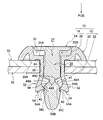
- an arrow PUS indicates the insertion direction of the two-piece clip into the mounting hole and the insertion direction of the pin into the grommet.
- the two-piece clip 10 of the present embodiment is made of synthetic resin, and the two-piece clip 10 includes a grommet 12 and a pin 14.
- the grommet 12 includes a base portion 20 and a body portion 22, and the pin 14 includes a head portion 24 and a shaft portion 26.
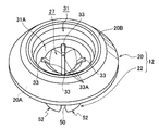
- the base 20 of the grommet 12 has a disk shape. As shown in FIG. 8, the base 20 of the grommet 12 is sized so as not to enter the mounting holes 34 and 36 of the two or more members 30 and 32 fastened by the two-piece clip 10. Further, a back surface 20 ⁇ / b> A that is a surface of the base portion 20 of the grommet 12 on the protruding side of the body portion 22 is a surface that is orthogonal to the central axis 23 of the body portion 22.
- the trunk portion 22 of the grommet 12 reaches the position where the back surface 20 ⁇ / b> A of the base portion 20 contacts the outer surface 30 ⁇ / b> A of the member 30 on the front side of the insertion with respect to the mounting holes 34 and 36 of the members 30 and 32. It can be inserted. Further, an insertion hole 27 is provided in a through state in the central portion of the base portion 20 of the grommet 12, and the shaft portion 26 of the pin 14 is inserted into the insertion hole 27. The insertion hole 27 is formed in the bottom 31 ⁇ / b> A of the recess 31 having a circular inner shape formed in the center of the base 20 of the grommet 12.
- the insertion hole 27 has a size that does not allow the head 24 of the pin 14 to enter, and the insertion hole 27 communicates with a space 29 in the trunk portion 22 of the grommet 12. Further, the recess 31 has a size that can accommodate the head 24 of the pin 14 and a depth that is greater than the thickness of the head 24 of the pin 14.
- the head 24 of the pin 14 is substantially in the same position as the top 20B of the base 20 of the grommet 12 and It does not protrude from 31.
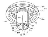
- the trunk portion 22 of the grommet 12 is divided into two or more (four in this embodiment) barrel component pieces 52 by slits 50 extending from the tip to the root.
- the body 22 is a cylindrical body with both ends open, and one end of the body 22 is integrated with the back surface 20A of the base 20 so that the in-cylinder space communicates with the insertion hole 27. ing.
- the slit 50 is formed from one end (tip) to the other end (root) of the barrel 22 that is a cylindrical body.
- the slits 50 are provided at four positions with substantially equal intervals between the slits 50 adjacent to each other in the circumferential direction of the cylindrical body, whereby the trunk portion 22 of the grommet 12 is provided with four barrel-constituting pieces 52. It is divided into
- an engagement convex portion 54 is formed on the tip side of each body component piece 52 of the grommet 12. At the positions where these engagement convex portions 54 are formed, the inner diameter of the space 29 in the body portion 22 is smaller than the maximum diameter of the shaft portion 26 of the pin 14. Further, the inner diameter of the space 29 in the body portion 22 from the position where these engagement convex portions 54 are formed to the base portion 20 is configured to be substantially equal to the maximum diameter of the shaft portion 26 of the pin 14.
- the engaging convex portion 54 of the grommet 12 has a distal-end-side convex wall surface 54A that inclines inward from the outside of the trunk portion 22 toward the base portion 20 side from the distal end side (the side opposite to the base portion 20) of the trunk portion 22.
- a head-side convex wall surface 54B that inclines inward from the outside of the trunk portion 22 from the base side (base portion 20 side) to the distal end side of the trunk portion 22 is provided.
- a top protrusion 54 ⁇ / b> C (convex portion) as a convex portion protruding inward (inward direction of the body portion 22) is formed from the inner end of the engaging convex portion 54.
- the cross-sectional shape along the axial direction of the grommet 12 of the top protrusion 54C is a curved shape (rounded shape).
- each guide recesses 33 are formed at the hole edge portion of the insertion hole 27 in the base portion 20 of the grommet 12 at substantially equal intervals in the circumferential direction. Further, the bottom surfaces of these guide recesses 33 are inclined so as to gradually protrude toward the center side of the base portion 20 from the top portion 20B side of the base portion 20 toward the back surface 20A side.
- the guide recess 33 ends with leaving the climbing portion 33 ⁇ / b> A between the end of the slit 50.
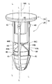
- the shaft portion 26 of the pin 14 is a round bar-like body whose tip is narrowed.
- a head-side engagement recess 44 is formed at a substantially middle position in the direction along the axis 14 ⁇ / b> A in the shaft portion 26 of the pin 14, and the tip side adjacent to the head-side engagement recess 44. Is formed with a tip-side engagement recess 40.
- the head-side engagement recess 44 is deeper (larger) than the tip-side engagement recess 40, and the engagement protrusion 54 of the grommet 12 does not fully enter the tip-side engagement recess 40 of the pin 14. However, it can enter the head-side engaging recess 44.
- a small protrusion 41 is formed on the distal end side of the distal end side engaging recess 40 in the shaft portion 26 of the pin 14, and in the vicinity of the head portion 24 in the shaft portion 26 of the pin 14, A small protrusion 43 is formed.
- the head-side engagement recess 44 has a recess-inner shape that follows the contour shape of the engagement protrusion 54 of the trunk-forming piece 52 in the grommet 12.
- the head-side engagement recesses 44 are provided at four locations with substantially equal intervals between the head-side engagement recesses 44 adjacent in the circumferential direction of the shaft portion 26 of the pin 14. ing.
- the head-side engaging recess 44 has both a tip-side recess wall surface 44A and a head-side recess wall surface 44C continuous to the tip-side recess wall surface 44A via the connecting shaft portion 44B.
- the tip-side engagement recess 40 of the pin 14 is formed only at a location adjacent to the two head-side engagement recesses 44 at opposite positions across the center of the shaft portion 26.
- these front end side engagement recessed parts 40 are shallow rectangular hollows long in the circumferential direction of the shaft part 26 so that only the top protrusions 54 ⁇ / b> C of the engagement convex parts 54 can enter.
- the body component pieces 52 of the grommet 12 that have started to bend outward at the reference position are removed from the head.
- the side engaging recess 44 is elastically returned to release the fastening of the pin 14 to the mounting holes 34 and 36 of the body portion 26. As a result, the two-piece clip 10 can be removed from the mounting holes 34 and 36.
- the tip-side recess wall surface 44 ⁇ / b> A of the head-side engagement recess 44 of the pin 14 is inclined inward from the outside of the shaft portion 26 toward the head 24 side from the tip side of the pin 14.
- the head-side recess wall surface 44C of the head-side engagement recess 44 of the pin 14 is inclined from the outer side of the shaft portion 26 toward the inner side from the head 24 side of the pin 14 toward the distal end side.
- the inner surface of the tip side concave wall surface 44A of the head side engaging concave portion 44 and the tip side convex wall surface 54A of the engaging convex portion 54 of the grommet 12 by the force of pushing back the tip portion of the pin 14 in the direction of extracting.
- the engaging projection 54 of the grommet 12 can be easily expanded outward by sliding the end. For this reason, the pin 14 is moved to the grommet 12 from the maximum pushing position shown in FIG. It is possible to return to the push-in position (reusable position).
- the pin retaining small protrusion 41 and the head side small protrusion 43 of the pin 14 are both imaginary straight lines L along the axis 14 ⁇ / b> A of the pin 14 passing between the adjacent head side engaging concave portions 44. It is provided above.
- the retaining small projections 41 are provided at two locations on both sides in the diameter direction of the shaft portion 26, and the head side small projections 43 are provided at four locations.
- the pin 14 is inserted into the body portion 26 of the grommet 12 through the insertion hole 27 of the grommet 12 only in a direction in which the small protrusion 41 of the pin 14 is inserted into the guide recess 33 (see FIG. 6) of the grommet 12.
- the shaft portion 26 can be inserted.
- the retaining projections 41 are elastically deformed so as to climb over the climbing portion 33A and enter the slit 50.
- the shaft portion 26 does not deflect the body component piece 52 outward, and the body portion 22 of the grommet 12 and the shaft portion 26 of the pin 14 are engaged.
- the small protrusion 41 of the pin 14 shown in FIG. 7 is caught by the end of the slit 50, the shaft portion 26 of the pin 14 is completely disengaged from the body portion 26 of the pin 14 without pushing the shaft portion 26 to the reference position. You will never get out of it.
- the inner peripheral portion 22 ⁇ / b> A of the body portion 22 of the grommet 14 and the outer peripheral portion 26 ⁇ / b> A of the shaft portion 26 of the pin 14 are in contact with each other on the surface extending in the direction along the axis 14 ⁇ / b> A of the pin 14. is doing. For this reason, the inner peripheral portion 22A of the body portion 22 of the grommet 12 and the outer peripheral portion 26A of the shaft portion 26 of the pin 14 are in close contact with each other on the surface extending in the direction along the axis 14A of the pin 14. .
- the inclination (rise) angle ⁇ ⁇ b> 1 of the head-side recess wall surface 44 ⁇ / b> C with respect to the axis 14 ⁇ / b> A of the pin 14 in the head-side engagement recess 44 formed on the pin 14 is the head-side engagement formed on the pin 14.
- the angle is wider ( ⁇ 1> ⁇ 2).
- a range in which the inner peripheral portion 22A of the body portion 22 of the grommet 12 and the outer peripheral portion 26A of the shaft portion 26 of the pin 14 are in close contact with each other can be extended longer toward the tip end side of the pin 14.
- the contact area between the inner peripheral portion 22A of the trunk portion 22 and the outer peripheral portion 26A of the shaft portion 26 of the pin 14 is increased. For this reason, in the state which fastened the members 30 and 32 so as not to be separated by the two-piece clip 10, the pin 14 is difficult to be removed from the grommet 12, and the removal resistance is improved.
- the inclination (rising) angle ⁇ 2 of the tip-side concave wall surface 44A of the head-side engagement concave portion 44 formed on the pin 14 with respect to the axis 14A of the pin 14 is the front-end convex portion of the engagement convex portion 54 formed on the grommet 12.
- the wall surface 54A has a narrower angle ( ⁇ 2 ⁇ 3) than the inclination (rise) angle ⁇ 3 of the pin 14 with respect to the axis 14A. Therefore, the gap 60 can be formed between the pin 14 and the grommet 12 in a state where the engagement convex portion 54 of the grommet 12 is in contact with the front end side concave wall surface 44 ⁇ / b> A of the head side engagement concave portion 44. For this reason, since the contact portion between the pin 14 and the grommet 12 is reduced, the force applied to the tip end of the pin 14 is concentrated on the contact portion between the pin 14 and the grommet 12 and is easily transmitted to the grommet side.
- the shaft portion 26 of the pin 14 is pushed into the trunk portion 22 of the grommet 12 to be a reference position.
- the engagement convex part 54 of the grommet 12 enters the front end side engaging concave part 40 of the pin 14, and the trunk
- the members 30 and 32 can be clamped between the trunk portion constituting piece 52 and the base portion 20 of the grommet 12 and the members 30 and 32 can be fastened together without being separated.
- the body constituting piece 52 of the grommet 12 is elastically restored, and the engaging convex portion 54 of the grommet 12 enters the head side engaging concave portion 44 of the pin 14, whereby the grommet 12 is fastened to the mounting holes 34 and 36.
- the state is released. For this reason, the two-piece clip 10 can be extracted from the attachment holes 34 and 36 and removed.
- the inner surface of the tip side concave wall surface 44A of the head side engaging concave portion 44 and the tip side convex wall surface 54A of the engaging convex portion 54 of the grommet 12 by the force of pushing back the tip portion of the pin 14 in the direction of extracting.
- the end slides, and the engaging projection 54 of the grommet 12 can be easily expanded.
- the pin 14 moves in the direction to be extracted from the grommet 12 (in the direction of arrow A in FIG. 1), passes through the reference position, and returns to the minimum push-in position (reusable state).
- the inner surface of the tip side concave wall surface 44A of the head side engaging concave portion 44 and the tip side convex wall surface 54A of the engaging convex portion 54 of the grommet 12 by the force of pushing back the tip portion of the pin 14 in the direction of extracting.
- the engaging projections 54 of the grommet 12 can be easily expanded outward by sliding the ends. For this reason, the pin 14 is moved to the grommet 12 from the maximum pushing position shown in FIG. It is possible to return to the push-in position (reusable state).
- the inner peripheral portion 22A of the trunk portion 22 of the grommet 14 and the outer peripheral portion 26A of the shaft portion 26 of the pin 14 are connected to the axis 14A of the pin 14. Are in contact with each other on the surfaces extending in the direction along. For this reason, the inner peripheral portion 22A of the trunk portion 22 of the grommet 12 and the outer peripheral portion 26A of the shaft portion 26 of the pin 14 are in close contact with each other on the surface extending in the direction along the axis 14A of the pin 14. The contact area between the inner peripheral portion 22A of the portion 22 and the outer peripheral portion 26A of the shaft portion 26 of the pin 14 is increased. As a result, in a state where the members 30 and 32 are fastened together by the two-piece clip 10, the pin 14 is difficult to be removed from the grommet 12, and the removal resistance is improved.
- the inclination angle ⁇ 1 with respect to the axis 14A of the pin 14 of the head-side recess wall surface 44C of the head-side engagement recess 44 formed on the pin 14 is
- the inclination angle ⁇ 2 of the tip-side recess wall surface 44A of the head-side engagement recess 44 formed on the pin 14 with respect to the axis 14A of the pin 14 is wider ( ⁇ 1> ⁇ 2).
- adhere can be extended long toward the front end side of the pin 14, and the grommet 12
- the contact area between the inner peripheral portion 22A of the body portion 22 and the outer peripheral portion 26A of the shaft portion 26 of the pin 14 can be increased.
- the pin 14 is difficult to be removed from the grommet 12, and the removal resistance is improved.
- the inclination angle ⁇ 2 of the tip-side concave wall surface 44A of the head-side engaging concave portion 44 formed on the pin 14 with respect to the axis 14A of the pin 14 is such that the front-side convex wall surface 54A of the engaging convex portion 54 formed on the grommet 12 is.
- the angle is narrower ( ⁇ 2 ⁇ 3) than the inclination angle ⁇ 3 of the pin 14 with respect to the axis 14A.
- a gap 60 can be formed between the pin 14 and the grommet 12, and the contact portion between the pin 14 and the grommet 12 becomes small, so that the force applied to the tip of the pin 14 is between the pin 14 and the grommet 12. It concentrates on the contact part and is easy to be transmitted to the grommet side. As a result, the operation force when returning the pin 14 to the reusable position with respect to the grommet 12 can be reduced, and workability is further improved.
- the top protrusion 54 ⁇ / b> C having a curved shape (rounded shape) is formed on the inner end of the engaging convex portion 54 of the grommet 12. For this reason, at the maximum pushing position, the pin 14 is pushed back in the direction in which the tip 14 is pulled out (the direction of arrow A in FIG. 1), and the body 22 of the grommet 12 is elastically deformed to the outside. The pin 14 and the grommet 12 are easily slid when the tip side concave wall surface 44 ⁇ / b> A and the top projection 54 ⁇ / b> C at the inner end of the engaging convex portion 54 of the grommet 12 slide. As a result, the operation force when returning the pin 14 to the reusable position with respect to the grommet 12 can be reduced, and the workability when returning the pin 14 to the reusable position is further improved.
- the present invention has been described in detail with respect to specific embodiments.
- the present invention is not limited to the above embodiments, and various other embodiments are possible within the scope of the present invention.
- the two-piece clip 10 is made of synthetic resin, but the material of the two-piece clip 10 is not limited to synthetic resin.
- the material of the grommet 12 and the material of the pin 14 may be different materials.
- three or more members may be fastened together.
Landscapes
- Engineering & Computer Science (AREA)
- General Engineering & Computer Science (AREA)
- Mechanical Engineering (AREA)
- Insertion Pins And Rivets (AREA)
- Installation Of Indoor Wiring (AREA)
- Connection Of Plates (AREA)
Abstract
Description
次に、本実施形態の2ピースクリップ10の構成について説明する。
図5及び図6に示すように、グロメット12の基部20は円盤状となっている。なお、図8に示すように、グロメット12の基部20は、2ピースクリップ10によって留め合される2以上の部材30、32の取付孔34、36に入り込まない大きさとなっている。また、グロメット12の基部20における胴部22の突き出し側の面である裏面20Aは、胴部22の中心軸23に直交する向きの面となっている。
図7に示すように、ピン14の軸部26は先端を窄ませた丸棒状体となっている。また、ピン14の軸部26における軸線14Aに沿った方向の略中程の位置には、頭部側係合凹部44が形成されており、この頭部側係合凹部44に隣接した先端側には、先端側係合凹部40が形成されている。なお、頭部側係合凹部44は先端側係合凹部40よりも深く(大きく)なっており、グロメット12の係合凸部54は、ピン14の先端側係合凹部40には入り込みきらないが、頭部側係合凹部44には入り込みきるようになっている。また、ピン14の軸部26における先端側係合凹部40よりも先端側には、抜け止め小突起41が形成されており、ピン14の軸部26における頭部24の近傍には頭部側小突起43が形成されている。
次に、本実施形態の2ピースクリップ10の取付け手順について説明する。
図2に示すように、グロメット12の胴部22に、ピン14の軸部26の先端部を入れ込ませた最小押し込み位置(再利用可能な位置)にある2ピースクリップ10を、部材30、32の取付孔34、36に挿入する。このとき、基部20の裏面20Aが挿通手前側にある部材30の外面に接しさせる位置まで挿通する。
次に、本実施形態の2ピースクリップ10の取外し手順について説明する。
図3に示すように、本実施形態の2ピースクリップ10によって部材30、32を離間しないように留め合わせた状態(基準位置)から、ピン14の頭部24を押し込んで、図4に示す最大押し込み位置とする。これにより、グロメット12の胴部構成片52が一旦外側に弾性変形して、ピン14の軸部26の先端側係合凹部40と、グロメット12の係合凸部54との係合が解除される。その後、グロメット12の胴部構成片52が弾性復帰し、グロメット12の係合凸部54がピン14の頭部側係合凹部44に入り込むことで、取付孔34、36に対するグロメット12の留め付け状態が解除される。このため、2ピースクリップ10を取付孔34、36から抜き出し、取り外すことができる。
次に、本実施形態の2ピースクリップ10を再使用可能な状態への復帰手順について説明する。
先ず、図1に示すように、最大押し込み位置にある2ピースクリップ10のピン14の先端部を、グロメット12に対して抜き出す方向(図1の矢印A方向)へ押し戻す。このとき、ピン14における頭部側係合凹部44の先端側凹部壁面44Aの中途に、グロメット12の係合凸部54の先端側凸部壁面54Aの内側端のみが当接している。
以上のように本実施形態の2ピースクリップ10では、図1に示すように、最大押し込み位置において、ピン14における頭部側係合凹部44の先端側凹部壁面44Aの中途に、グロメット12の係合凸部54の先端側凸部壁面54Aの内側端が当接している。このため、ピン14の先端部を抜き出す方向(図1の矢印A方向)へ押し戻すと、ピン14の頭部側係合凹部44の先端側凹部壁面44Aと、グロメット12の係合凸部54の先端側凸部壁面54Aの内側端とが摺動することで、グロメット12の各胴部構成片52を外側方向(図1の矢印B方向)に容易に弾性変形させることができる。即ち、ピン14の先端部を抜き出す方向へ押し戻す力によって、ピン14における頭部側係合凹部44の先端側凹部壁面44Aと、グロメット12の係合凸部54の先端側凸部壁面54Aの内側端とを摺動させ、グロメット12の係合凸部54を容易に外側方向へ広げることができる。このため、ピン14の先端部を抜き出す方向へ押し戻すという簡単、かつ操作力を低減可能な操作で、ピン14をグロメット12に対して、図1に示す最大押し込み位置から、基準位置を経て、最小押し込み位置(再使用可能な状態)へ戻すことができる。
以上に於いては、本発明を特定の実施形態について詳細に説明したが、本発明は上記実施形態に限定されるものではなく、本発明の範囲内にて他の種々の実施形態が可能であることは当業者にとって明らかである。例えば、上記実施形態では、2ピースクリップ10を合成樹脂製としたが、2ピースクリップ10の材質は合成樹脂製に限定されない。また、グロメット12の材質とピン14の材質とを異なる材質としてもよい。さらに、上記実施形態の2ピースクリップ10において、3つ以上の部材を留め合わせてもよい。
Claims (5)
- 先端から根元に亘る2以上のスリットによって分割され且つ先端部に係合凸部が形成され、重ねた部材の取付孔に挿入される胴部と、前記胴部の根元部に設けられ前記部材の取付孔の周縁部に当接する基部と、を備えたグロメットと、
前記グロメットの胴部に押し込み可能とされた軸部と、前記軸部の一方の端部に設けられた頭部と、を備えたピンと、
前記ピンの軸部に形成され、前記ピンを前記グロメットに所定量押し込んだ基準位置において前記グロメットの係合凸部が係合し、前記グロメットの胴部を外側に弾性変形させて前記胴部と前記基部とで前記部材を挟持させる先端側係合凹部と、
前記ピンの軸部における前記先端側係合凹部より前記頭部側に形成され、前記ピンを前記グロメットに前記基準位置よりさらに押し込んだ最大押し込み位置において、前記胴部の係合凸部が係合し、前記グロメットの胴部を内側に弾性復帰させて前記取付孔を通過可能とする頭部側係合凹部と、
を有し、
前記グロメットの前記係合凸部は、前記胴部の先端側から前記胴部の内側方向へ傾斜する先端側凸部壁面と、前記グロメットの基部側から前記胴部の内側方向へ傾斜する基部側凸部壁面と、を備え、
前記ピンの前記頭部側係合凹部は、先端側から前記軸部の内側方向へ傾斜する先端側凹部壁面と、前記ピンの頭部側から前記軸部の内側方向へ傾斜する頭部側凹部壁面と、を備え、
前記最大押し込み位置において、前記頭部側係合凹部の先端側凹部壁面の中途に前記係合凸部の先端側凸部壁面の内側端が当接する2ピースクリップ。 - 前記グロメットの胴部の内周部と前記ピンの軸部の外周部とが前記ピンの軸線に沿った方向に延在する面において互いに接触している請求項1に記載の2ピースクリップ。
- 前記ピンに形成した頭部側係合凹部における頭部側凹部壁面の前記ピンの軸線に対する傾斜角度が、前記ピンに形成した頭部側係合凹部における先端側凹部壁面の前記ピンの軸線に対する傾斜角度に比べて広角である請求項1または請求項2に記載の2ピースクリップ。
- 前記ピンに形成した頭部側係合凹部における先端側凹部壁面の前記ピンの軸線に対する傾斜角度が、前記グロメットに形成した係合凸部における先端側凸部壁面の前記ピンの軸線に対する傾斜角度に比べて狭角である請求項1~3の何れか1項に記載の2ピースクリップ。
- 前記グロメットの係合凸部の内側端に湾曲形状の凸部が形成されている請求項1~4の何れか1項に記載の2ピースクリップ。
Priority Applications (4)
| Application Number | Priority Date | Filing Date | Title |
|---|---|---|---|
| EP11850490.1A EP2657545B1 (en) | 2010-12-24 | 2011-12-20 | Two-piece clip |
| US13/997,502 US9103363B2 (en) | 2010-12-24 | 2011-12-20 | Two-piece clip assembly |
| KR1020137019203A KR101481360B1 (ko) | 2010-12-24 | 2011-12-20 | 2피스 클립 |
| CN201180062331.2A CN103270323B (zh) | 2010-12-24 | 2011-12-20 | 两件套卡夹 |
Applications Claiming Priority (2)
| Application Number | Priority Date | Filing Date | Title |
|---|---|---|---|
| JP2010-288942 | 2010-12-24 | ||
| JP2010288942A JP5701593B2 (ja) | 2010-12-24 | 2010-12-24 | 2ピースクリップ |
Publications (1)
| Publication Number | Publication Date |
|---|---|
| WO2012086652A1 true WO2012086652A1 (ja) | 2012-06-28 |
Family
ID=46313920
Family Applications (1)
| Application Number | Title | Priority Date | Filing Date |
|---|---|---|---|
| PCT/JP2011/079549 Ceased WO2012086652A1 (ja) | 2010-12-24 | 2011-12-20 | 2ピースクリップ |
Country Status (6)
| Country | Link |
|---|---|
| US (1) | US9103363B2 (ja) |
| EP (1) | EP2657545B1 (ja) |
| JP (1) | JP5701593B2 (ja) |
| KR (1) | KR101481360B1 (ja) |
| CN (1) | CN103270323B (ja) |
| WO (1) | WO2012086652A1 (ja) |
Cited By (2)
| Publication number | Priority date | Publication date | Assignee | Title |
|---|---|---|---|---|
| US20140341674A1 (en) * | 2011-09-16 | 2014-11-20 | Nifco Inc. | Fastener |
| WO2025234316A1 (ja) * | 2024-05-08 | 2025-11-13 | 株式会社ニフコ | クリップ |
Families Citing this family (26)
| Publication number | Priority date | Publication date | Assignee | Title |
|---|---|---|---|---|
| JP5336284B2 (ja) * | 2009-07-15 | 2013-11-06 | 株式会社ニフコ | 2ピースクリップ |
| JP6126958B2 (ja) * | 2013-09-19 | 2017-05-10 | 株式会社ニフコ | クリップ |
| AU2014359722B2 (en) * | 2013-12-02 | 2016-08-11 | Aesculap Ag | Security seal for medical sterile container |
| AT515173B1 (de) * | 2013-12-13 | 2016-11-15 | Ultimate Europe Transp Equipment Gmbh | Befestigungssystem |
| US9528540B2 (en) | 2014-08-12 | 2016-12-27 | Newfrey Llc | Insertion-locking pin and grommet and related methods |
| US10030682B2 (en) | 2014-08-25 | 2018-07-24 | Ford Global Technologies, Llc | Two-part fastener |
| DE202015104382U1 (de) | 2015-08-25 | 2015-09-08 | Ford Global Technologies, Llc | Zweiteiliges Befestigungselement |
| JP6396277B2 (ja) * | 2015-11-26 | 2018-09-26 | 株式会社ニフコ | クリップ |
| US9873388B2 (en) * | 2016-04-06 | 2018-01-23 | Newfrey Llc | Automotive door trim fastener and molding method |
| GB2551367B (en) * | 2016-06-15 | 2019-03-27 | Ford Motor Co | Temporary fastener assembly |
| JP6669623B2 (ja) * | 2016-09-23 | 2020-03-18 | 株式会社ニフコ | 部材取付構造及び取付クリップ |
| WO2019038990A1 (ja) | 2017-08-24 | 2019-02-28 | 株式会社ニフコ | クリップ |
| JP6850773B2 (ja) * | 2018-08-22 | 2021-03-31 | 株式会社ニフコ | クリップ |
| JP6547237B1 (ja) * | 2019-02-26 | 2019-07-24 | 千住金属工業株式会社 | はんだ付け装置及びはんだ付け装置にパッキンを固定する方法 |
| CN111664153B (zh) * | 2019-03-08 | 2024-05-24 | 伊利诺斯工具制品有限公司 | 铆钉型紧固件 |
| US10900513B2 (en) | 2019-04-02 | 2021-01-26 | Newfrey Llc | Re-usable one-push pin and grommet fastener |
| CN111609013A (zh) * | 2020-05-29 | 2020-09-01 | 京信通信技术(广州)有限公司 | 一种止退型铆钉和天线 |
| US20220065281A1 (en) * | 2020-09-03 | 2022-03-03 | Milbank Manufacturing Co. | Plumb adjuster for electrical enclosure |
| CN112924003B (zh) * | 2021-01-25 | 2022-08-26 | 柴沙沙 | 一种基础数学用电子天平 |
| JP7663884B2 (ja) * | 2021-04-30 | 2025-04-17 | 国立研究開発法人宇宙航空研究開発機構 | 結合部材 |
| CN115370649A (zh) * | 2021-05-19 | 2022-11-22 | 伊利诺斯工具制品有限公司 | 索环及紧固件组件 |
| US12092138B2 (en) * | 2022-04-08 | 2024-09-17 | Toyota Motor Engineering & Manufacturing North America, Inc. | Coupling assemblies having frangible portions |
| CN114810774A (zh) * | 2022-05-19 | 2022-07-29 | 无锡安士达五金有限公司 | 一种轻型自锁铆钉 |
| US12326163B2 (en) | 2022-09-07 | 2025-06-10 | Newfrey Llc | Pin and grommet fastener including pin and grommet having panel retention fingers and pin retention fingers that cooperate with one another to define pin receptacle for receiving the pin |
| CN116398522B (zh) * | 2023-04-26 | 2026-04-17 | 重庆长安汽车股份有限公司 | 卡扣及车饰组件 |
| CN120830673A (zh) * | 2024-04-16 | 2025-10-24 | 上海理想汽车科技有限公司 | 锁芯、卡接组件、车身地板和车辆 |
Citations (4)
| Publication number | Priority date | Publication date | Assignee | Title |
|---|---|---|---|---|
| JPH0247414U (ja) * | 1988-09-29 | 1990-03-30 | ||
| JPH07208423A (ja) * | 1994-01-24 | 1995-08-11 | Pop Rivet Fastener Kk | プラスチック製ブラインドリベット |
| JP2007056895A (ja) * | 2005-08-22 | 2007-03-08 | Nifco Inc | クリップ |
| JP4423266B2 (ja) | 2006-01-25 | 2010-03-03 | 株式会社ニフコ | グロメット |
Family Cites Families (12)
| Publication number | Priority date | Publication date | Assignee | Title |
|---|---|---|---|---|
| JPH0442568Y2 (ja) * | 1985-06-19 | 1992-10-08 | ||
| JPH032003Y2 (ja) * | 1986-09-26 | 1991-01-21 | ||
| JPS6414912U (ja) * | 1987-07-16 | 1989-01-25 | ||
| JPH0524807Y2 (ja) * | 1987-12-04 | 1993-06-23 | ||
| AU626479B2 (en) * | 1989-12-12 | 1992-07-30 | W.A. Deutsher Pty Ltd | Two part fastener |
| US5201623A (en) * | 1992-02-18 | 1993-04-13 | Emhart Inc. | Two stage rivet |
| JP2004028244A (ja) * | 2002-06-27 | 2004-01-29 | Nippon Pop Rivets & Fasteners Ltd | クリップ及び部材連結装置 |
| JP4091859B2 (ja) * | 2003-03-03 | 2008-05-28 | 株式会社パイオラックス | 締結具 |
| US7736107B2 (en) * | 2004-03-30 | 2010-06-15 | Piolax, Inc. | Clipping device |
| JP4485281B2 (ja) * | 2004-08-05 | 2010-06-16 | 株式会社ニフコ | 留め具 |
| DE102005021940A1 (de) * | 2005-05-12 | 2006-11-30 | Volkswagen Ag | Verbindungseinrichtung, Formgebungseinrichtung sowie Verfahren zur Herstellung einer Verbindungseinrichtung |
| WO2009008185A1 (ja) * | 2007-07-12 | 2009-01-15 | Piolax Inc. | 留め具 |
-
2010
- 2010-12-24 JP JP2010288942A patent/JP5701593B2/ja active Active
-
2011
- 2011-12-20 US US13/997,502 patent/US9103363B2/en active Active
- 2011-12-20 CN CN201180062331.2A patent/CN103270323B/zh active Active
- 2011-12-20 KR KR1020137019203A patent/KR101481360B1/ko active Active
- 2011-12-20 EP EP11850490.1A patent/EP2657545B1/en active Active
- 2011-12-20 WO PCT/JP2011/079549 patent/WO2012086652A1/ja not_active Ceased
Patent Citations (4)
| Publication number | Priority date | Publication date | Assignee | Title |
|---|---|---|---|---|
| JPH0247414U (ja) * | 1988-09-29 | 1990-03-30 | ||
| JPH07208423A (ja) * | 1994-01-24 | 1995-08-11 | Pop Rivet Fastener Kk | プラスチック製ブラインドリベット |
| JP2007056895A (ja) * | 2005-08-22 | 2007-03-08 | Nifco Inc | クリップ |
| JP4423266B2 (ja) | 2006-01-25 | 2010-03-03 | 株式会社ニフコ | グロメット |
Non-Patent Citations (1)
| Title |
|---|
| See also references of EP2657545A4 * |
Cited By (3)
| Publication number | Priority date | Publication date | Assignee | Title |
|---|---|---|---|---|
| US20140341674A1 (en) * | 2011-09-16 | 2014-11-20 | Nifco Inc. | Fastener |
| US9341210B2 (en) * | 2011-09-16 | 2016-05-17 | Nifco Inc. | Fastener |
| WO2025234316A1 (ja) * | 2024-05-08 | 2025-11-13 | 株式会社ニフコ | クリップ |
Also Published As
| Publication number | Publication date |
|---|---|
| JP5701593B2 (ja) | 2015-04-15 |
| KR20130115329A (ko) | 2013-10-21 |
| US9103363B2 (en) | 2015-08-11 |
| EP2657545A1 (en) | 2013-10-30 |
| CN103270323A (zh) | 2013-08-28 |
| US20130287517A1 (en) | 2013-10-31 |
| CN103270323B (zh) | 2015-08-12 |
| EP2657545B1 (en) | 2021-09-08 |
| KR101481360B1 (ko) | 2015-01-21 |
| JP2012137130A (ja) | 2012-07-19 |
| EP2657545A4 (en) | 2018-01-03 |
Similar Documents
| Publication | Publication Date | Title |
|---|---|---|
| JP5701593B2 (ja) | 2ピースクリップ | |
| JP6563854B2 (ja) | 管状体のロック機構 | |
| CN101573553B (zh) | 连接器、用于所述连接器的插座和插头 | |
| JP2010029629A (ja) | クリップ処置具 | |
| JP4864799B2 (ja) | ホースクランプ | |
| CN111033062B (zh) | 卡夹 | |
| JP2009281581A (ja) | クリップ | |
| KR20100122856A (ko) | 체결구 | |
| JP2007315517A (ja) | 2ピースクリップ | |
| JP2018071750A (ja) | 車両用固定部品 | |
| RU2002104971A (ru) | Вставное соединительное устройство трубки пылесоса | |
| JP6396277B2 (ja) | クリップ | |
| JP2005188647A (ja) | ロッドの連結構造 | |
| JP4423266B2 (ja) | グロメット | |
| JP5210207B2 (ja) | クリップと取付部材との組付構造 | |
| JP2009042767A (ja) | 抜き治具付きプラグ | |
| JP5107416B2 (ja) | ロッドの連結構造 | |
| JP5722816B2 (ja) | 連結継手、調芯部材及びセグメント | |
| JP2010092689A (ja) | 電気コネクタ | |
| JP4589815B2 (ja) | ロッドの連結構造 | |
| JP2013085604A (ja) | パイプの連結構造及びこれを用いた掃除具 | |
| JP5826014B2 (ja) | 管接続構造 | |
| JP2012082955A (ja) | クリップ | |
| JP6377493B2 (ja) | 管継手の接続構造 | |
| JP2010007862A (ja) | パイプの連結構造 |
Legal Events
| Date | Code | Title | Description |
|---|---|---|---|
| 121 | Ep: the epo has been informed by wipo that ep was designated in this application |
Ref document number: 11850490 Country of ref document: EP Kind code of ref document: A1 |
|
| NENP | Non-entry into the national phase |
Ref country code: DE |
|
| WWE | Wipo information: entry into national phase |
Ref document number: 13997502 Country of ref document: US |
|
| WWE | Wipo information: entry into national phase |
Ref document number: 2011850490 Country of ref document: EP |
|
| ENP | Entry into the national phase |
Ref document number: 20137019203 Country of ref document: KR Kind code of ref document: A |