WO2012086675A1 - 成型装置および同成型装置による成型方法 - Google Patents
成型装置および同成型装置による成型方法 Download PDFInfo
- Publication number
- WO2012086675A1 WO2012086675A1 PCT/JP2011/079610 JP2011079610W WO2012086675A1 WO 2012086675 A1 WO2012086675 A1 WO 2012086675A1 JP 2011079610 W JP2011079610 W JP 2011079610W WO 2012086675 A1 WO2012086675 A1 WO 2012086675A1
- Authority
- WO
- WIPO (PCT)
- Prior art keywords
- molding
- mold
- molding part
- die
- product
- Prior art date
- Legal status (The legal status is an assumption and is not a legal conclusion. Google has not performed a legal analysis and makes no representation as to the accuracy of the status listed.)
- Ceased
Links
Images


Classifications
-
- B—PERFORMING OPERATIONS; TRANSPORTING
- B29—WORKING OF PLASTICS; WORKING OF SUBSTANCES IN A PLASTIC STATE IN GENERAL
- B29C—SHAPING OR JOINING OF PLASTICS; SHAPING OF MATERIAL IN A PLASTIC STATE, NOT OTHERWISE PROVIDED FOR; AFTER-TREATMENT OF THE SHAPED PRODUCTS, e.g. REPAIRING
- B29C45/00—Injection moulding, i.e. forcing the required volume of moulding material through a nozzle into a closed mould; Apparatus therefor
- B29C45/17—Component parts, details or accessories; Auxiliary operations
- B29C45/72—Heating or cooling
- B29C45/73—Heating or cooling of the mould
-
- B—PERFORMING OPERATIONS; TRANSPORTING
- B29—WORKING OF PLASTICS; WORKING OF SUBSTANCES IN A PLASTIC STATE IN GENERAL
- B29C—SHAPING OR JOINING OF PLASTICS; SHAPING OF MATERIAL IN A PLASTIC STATE, NOT OTHERWISE PROVIDED FOR; AFTER-TREATMENT OF THE SHAPED PRODUCTS, e.g. REPAIRING
- B29C33/00—Moulds or cores; Details thereof or accessories therefor
- B29C33/02—Moulds or cores; Details thereof or accessories therefor with incorporated heating or cooling means
- B29C33/08—Moulds or cores; Details thereof or accessories therefor with incorporated heating or cooling means for dielectric heating
-
- B—PERFORMING OPERATIONS; TRANSPORTING
- B29—WORKING OF PLASTICS; WORKING OF SUBSTANCES IN A PLASTIC STATE IN GENERAL
- B29C—SHAPING OR JOINING OF PLASTICS; SHAPING OF MATERIAL IN A PLASTIC STATE, NOT OTHERWISE PROVIDED FOR; AFTER-TREATMENT OF THE SHAPED PRODUCTS, e.g. REPAIRING
- B29C33/00—Moulds or cores; Details thereof or accessories therefor
- B29C33/02—Moulds or cores; Details thereof or accessories therefor with incorporated heating or cooling means
-
- B—PERFORMING OPERATIONS; TRANSPORTING
- B29—WORKING OF PLASTICS; WORKING OF SUBSTANCES IN A PLASTIC STATE IN GENERAL
- B29C—SHAPING OR JOINING OF PLASTICS; SHAPING OF MATERIAL IN A PLASTIC STATE, NOT OTHERWISE PROVIDED FOR; AFTER-TREATMENT OF THE SHAPED PRODUCTS, e.g. REPAIRING
- B29C33/00—Moulds or cores; Details thereof or accessories therefor
- B29C33/02—Moulds or cores; Details thereof or accessories therefor with incorporated heating or cooling means
- B29C33/04—Moulds or cores; Details thereof or accessories therefor with incorporated heating or cooling means using liquids, gas or steam
-
- B—PERFORMING OPERATIONS; TRANSPORTING
- B29—WORKING OF PLASTICS; WORKING OF SUBSTANCES IN A PLASTIC STATE IN GENERAL
- B29C—SHAPING OR JOINING OF PLASTICS; SHAPING OF MATERIAL IN A PLASTIC STATE, NOT OTHERWISE PROVIDED FOR; AFTER-TREATMENT OF THE SHAPED PRODUCTS, e.g. REPAIRING
- B29C45/00—Injection moulding, i.e. forcing the required volume of moulding material through a nozzle into a closed mould; Apparatus therefor
- B29C45/17—Component parts, details or accessories; Auxiliary operations
- B29C45/72—Heating or cooling
-
- B—PERFORMING OPERATIONS; TRANSPORTING
- B29—WORKING OF PLASTICS; WORKING OF SUBSTANCES IN A PLASTIC STATE IN GENERAL
- B29C—SHAPING OR JOINING OF PLASTICS; SHAPING OF MATERIAL IN A PLASTIC STATE, NOT OTHERWISE PROVIDED FOR; AFTER-TREATMENT OF THE SHAPED PRODUCTS, e.g. REPAIRING
- B29C33/00—Moulds or cores; Details thereof or accessories therefor
- B29C33/02—Moulds or cores; Details thereof or accessories therefor with incorporated heating or cooling means
- B29C2033/023—Thermal insulation of moulds or mould parts
-
- B—PERFORMING OPERATIONS; TRANSPORTING
- B29—WORKING OF PLASTICS; WORKING OF SUBSTANCES IN A PLASTIC STATE IN GENERAL
- B29C—SHAPING OR JOINING OF PLASTICS; SHAPING OF MATERIAL IN A PLASTIC STATE, NOT OTHERWISE PROVIDED FOR; AFTER-TREATMENT OF THE SHAPED PRODUCTS, e.g. REPAIRING
- B29C45/00—Injection moulding, i.e. forcing the required volume of moulding material through a nozzle into a closed mould; Apparatus therefor
- B29C45/17—Component parts, details or accessories; Auxiliary operations
- B29C45/72—Heating or cooling
- B29C45/73—Heating or cooling of the mould
- B29C2045/7368—Heating or cooling of the mould combining a heating or cooling fluid and non-fluid means
Definitions
- a molded material having plasticity or fluidity is disposed (including injection) in a pair of molds formed in a three-dimensional shape corresponding to the surface shape of the product to be molded.
- the present invention relates to a molding apparatus for molding and a molding method using the molding apparatus.
- a molding apparatus that performs molding processing by placing a molding material having plasticity or fluidity, for example, a resin material or a metal material in a pair of molds.
- the molding part for molding the molding material in the mold is preliminarily heated before molding the molding material, so that the plastic material or the fluidity of the molding material is prevented from being lowered and molded accurately. It is known that it can be processed.
- an inductor is arranged around the mold or in the molding part of the mold and the mold or the molding part is placed.
- Induction heating method for induction heating see Patent Documents 1 and 2 below
- Heat source embedding method for heating a mold or a molding part by providing a flow path for heating wire or heated fluid inside the mold Patent Documents 3 and 3 below
- an external heat source system that heats the mold or molded part by supplying a heated fluid (such as a heating wire or an infrared lamp) to the molded part of the mold or supplying a heated fluid (the following patent document) 5 and 6)
- a surface layer energization method Patent Document 7 below
- the surface energization method has a shorter cycle time until
- the present invention has been made to cope with the above problems, and its purpose is to provide a molding apparatus capable of heating the molding section with a simple configuration while ensuring the durability of the molding section in the mold, and molding by the molding apparatus. It is to provide a method.
- the feature of the present invention according to claim 1 is that a first mold having a first molding part formed in a three-dimensional shape corresponding to a part of the surface of a product to be molded, A second mold having a second molding part formed in a three-dimensional shape corresponding to another part of the surface of the product and disposed opposite to the first mold; the first molding part and the second molding part
- a molding apparatus that molds a product by placing a material to be molded between the molding part, a mold energizing means for flowing electricity to at least one of the first mold and the second mold is provided,
- the thickness of the first molding part and / or the second molding part to be energized is formed around the first molding part and / or the second molding part. It exists in being formed in thickness thinner than the thickness of the outer peripheral part which supports 1 molding part and / or the 2nd molding part.
- the molding apparatus includes a first mold and / or a first molding part and / or a second molding part for forming the surface of the product.
- a mold energizing means for energizing the second mold is provided.
- the thickness of the first molding part and / or the second molding part energized by the mold energizing means is greater than the thickness of the outer peripheral part of the mold formed around the first molding part and the second molding part. It is thin. That is, the cross-sectional area of the first molding part and / or the second molding part, which is the part to be heated, decreases and the resistance value of the same part increases.
- the first molding part and / or the second molding part is formed with a uniform thickness with the outer peripheral part of the mold. Compared with the case where it is done, it can heat early with little electric energy. In this case, since the first molding part and / or the second molding part do not require the conductive layer and the insulating layer in the prior art, the manufacturing and maintenance man-hours of the mold are reduced. That is, in the molding apparatus according to the present invention, it is possible to heat with a simple configuration while ensuring the durability of the molding part in the mold.
- the first mold and / or the second mold is formed of a first molding part and / or a second molding part formed thin.
- a cavity is formed on the back side along the first molding part and / or the second molding part.
- the molding apparatus is provided on the back side of the first molding part and / or the second molding part in the first mold and / or the second mold.
- a cavity is formed along the first molding part and / or the second molding part.
- the back side of the first molding part and the second molding part means the side opposite to the surface on which the first molding part and the second molding part mold the material to be molded.
- a current that is about to flow through the first mold and / or the second mold by the shortest path can be guided to the first mold part and / or the second mold part, and the first mold and / or the second mold can be guided.
- the inside of the mold can be efficiently heated.
- the weight of the molding apparatus can be reduced by the cavity formed in the first mold and / or the second mold, and the cavity formed in the first mold and / or the second mold can be reduced.
- Other members, parts, mechanisms or the like constituting the molding apparatus can be accommodated, and the configuration of the molding apparatus can be further reduced in size.
- a cooling fluid supply unit that supplies cooling fluid to the first molding unit and / or the second molding unit in the cavity. It is in having established.
- the molding apparatus supplies the cooling fluid to the first molding part and / or the second molding part in the cavity.
- Supply means are provided.
- various liquids and gases such as water, oil, liquid nitrogen, water vapor or air can be used as the cooling fluid.
- die provided with the cooling fluid supply means can cool the 1st molding part and / or 2nd molding part in a heating state at an early stage. In this case, since the thickness of the first molding part and / or the second molding part is formed thin, it can be cooled earlier and reheated earlier.
- a rib for supporting the first molding part and / or the second molding part is further provided in the hollow part.
- the molding device is provided with ribs for supporting the first molding part and / or the second molding part in the cavity.
- thickness reduction can be achieved, ensuring the rigidity of the 1st molding part and / or the 2nd molding part, and the 1st molding part and / or the 2nd molding part can be heated more efficiently.
- a temperature measurement sensor for measuring the temperature of the first molding part and / or the second molding part is further provided in the cavity. There is.
- the molding apparatus includes a temperature measurement sensor for measuring the temperature of the first molding unit and / or the second molding unit in the cavity. Is provided. Thereby, since the temperature condition of the 1st molding part and / or the 2nd molding part can be grasped, the temperature of the 1st molding part and / or the 2nd molding part can be controlled appropriately, and it is more efficient. In addition, the molded product can be molded with high accuracy.
- the mold energizing means in the molding apparatus, includes an electrical connection portion that electrically connects and disconnects the first mold and the second mold. It is in.
- molding apparatus is an electrical connection part in which a metal mold
- the mold energization means can energize the first mold and the second mold by one power supply device through the electrical connection portion, and the configuration of the molding apparatus can be simplified.
- an insulator is provided in an outer peripheral portion between the first mold and the second mold.
- the molding apparatus is provided with an insulator at an outer peripheral portion between the first mold and the second mold. For this reason, it can energize in the closed state where the 1st metallic mold and the 2nd metallic mold were stuck. Thereby, by energizing and heating one of the first mold and the second mold, the other second mold or the first mold can be heated by heat conduction. Moreover, since it can heat in the state which closed the 1st metal mold
- the present invention can be implemented not only as a molding apparatus but also as an invention of a molding method using the molding apparatus.
- the feature of the present invention according to claim 8 is that a first mold having a first molding part formed in a three-dimensional shape corresponding to a part of the surface of a product to be molded, A second molding part having a second molding part formed in a three-dimensional shape corresponding to another part of the surface and disposed opposite to the first mold, the first molding part and the second molding part
- a molding method of molding a product by placing a material to be molded between the thickness of at least one of the first molding part and the second molding part, the thickness of the first molding part and / or the second molding part
- the first molding part and / or the second molding part formed in the periphery and formed to be thinner than the thickness of the outer peripheral part that supports the first molding part and / or the second molding part.
- the molded part is heated, it is to cast an object to be molded material to the product by the first molded part which is heated and / or the second molded section.
- cooling fluid is supplied from the cooling fluid supply means to the first molding unit and / or the second molding unit to cool the first molding unit and / or the second molding unit. It is good to do.
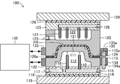
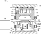
- FIG. 1 is a cross-sectional view schematically showing the outline of the configuration of the main part of a molding apparatus 100 according to the present invention.
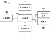
- FIG. 2 is a block diagram of a control system that controls the operation of the molding apparatus 100. Note that each drawing referred to in the present specification is schematically represented by exaggerating some of the components in order to facilitate understanding of the present invention. For this reason, the dimension, ratio, etc. between each component may differ.
- the molding apparatus 100 is a processing machine that manufactures a product PR made of FRP (fiber reinforced plastic) by compressing and molding a material to be molded in which a thermoplastic resin sheet and a fiber sheet are laminated.
- the product PR corresponds to various parts constituting a two-wheeled or four-wheeled motor vehicle, a ship and an aircraft, and various parts constituting a drive system for driving them.
- FRP fiber reinforced plastic
- the molding apparatus 100 includes a first mold 110 and a second mold 120.
- the first mold 110 and the second mold 120 are steel molds that perform molding processing of a material to be molded in cooperation with each other, and the first molding section 111 and the second molding are formed at the center of the surfaces facing each other.
- Each part 121 is formed.
- the first molding part 111 and the second molding part 121 are parts that actually perform molding by applying heat and compressive force to the material to be molded, and more specifically, a three-dimensional shape corresponding to the surface shape of the product PR. Are each formed into a three-dimensional shape obtained by inverting the three-dimensional shape of the surface of the product PR.
- the first molding part 111 is configured by a so-called core formed in a shape protruding in a convex shape toward the upper side in the drawing corresponding to the concave shape on the lower surface in the product PR.
- the first molding portion 111 in the first mold 110 is formed with a thickness (thickness in the vertical direction in the drawing) that is thinner than the thickness (thickness in the vertical direction in the drawing) of the first outer peripheral portion 110a of the first mold 110.
- the first outer peripheral portion 110 a is a portion formed in a planar shape around the first molding portion 111 in the first mold 110, and the second mold 120 facing the second outer peripheral portion 120 a in the second mold 120. It is also a split surface.
- the first molding part 111 is formed inside the first outer peripheral part 110a.
- the first outer peripheral portion 110a is formed with a thickness capable of suppressing deformation of the first molding portion 111 when the first die 110 receives a pressing force from the second die 120.
- the thickness of the first outer peripheral portion 110a of the first mold 110 is formed to be about 150 mm, and the thickness of the first molding portion 111 is formed to be about 20 mm.
- a first hollow part 112 having a concave shape is formed on the opposite side of the first mold 110 from the first molding part 111.
- the first cavity portion 112 is formed in a concave shape along the convex shape of the first molding portion 111. More specifically, the first cavity portion 112 is formed along the first molding portion 111, and the inner wall surface facing the first molding portion 111 has a shape corresponding to the shape of the first molding portion 111, That is, it is formed in a shape that maintains the thickness of the first molding portion 111 to be thinner than the thickness of the second outer peripheral portion 110a.
- the second molding portion 122 is constituted by a so-called cavity formed in a concave shape toward the lower side of the drawing corresponding to the convex shape of the upper surface of the product PR.
- the second molding portion 121 in the second mold 120 is formed with a thickness that is thinner than the thickness of the second outer peripheral portion 120 a of the second mold 120.
- the second outer peripheral portion 120 a is a portion formed in a planar shape around the second molding portion 121 in the second mold 120, similar to the first outer peripheral portion 110 a, and in the first mold 110. It is a division surface with the 1st metal mold
- the second molding part 121 is formed inside the second outer peripheral part 120a.
- the second outer peripheral portion 120 a can suppress deformation of the second molding portion 121 when the second die 110 receives a reaction force from the first die 110 when the first die 110 is pressed. It is formed with a wall thickness. In the present embodiment, the thickness of the second outer peripheral portion 120a of the second mold 120 is formed to be about 150 mm, and the thickness of the second molding portion 121 is formed to be about 20 mm.
- a second hollow part 122 having a concave shape is formed on the opposite side of the second molding part 121 in the second mold 120.
- the second cavity portion 122 is formed in a concave shape along the illustrated horizontal portion of the deepest portion in the second molding portion 121. More specifically, the second cavity part 122 is formed along the second molding part 121, and the inner wall surface facing the second molding part 121 corresponds to the shape of the second molding part 121, That is, it is formed in a shape that maintains the thickness of the second molding portion 121 to be thinner than the thickness of the second outer peripheral portion 120a.
- a drainage hole 123 is formed in the second cavity portion 122 in communication with the deepest horizontal portion shown in the drawing.
- the drainage hole 123 is a hole extending in a tubular shape for draining the cooling water accumulated in the second cavity part 122 to the outside of the second mold 120, and has one end communicating with the second cavity part 122.
- the other end of the second mold 120 is formed so as to open on the left side surface of the figure.
- the drain hole 123 is connected to a drain pipe (not shown) at the other end that opens to the left side surface of the second mold 120 in the figure.
- heat insulating insulators 113 and 124 are provided on the first outer peripheral portion 110a and the second outer peripheral portion 120a in the first mold 110 and the second mold 120, respectively.
- the heat insulating insulators 113 and 124 are used to insulate and hold the outside of the molding region where the first mold 110 and the second mold 120 are closed, and to electrically insulate the first mold 110 and the second mold 120 from each other. It is a member for doing.
- the heat insulating insulators 113 and 124 are formed on the first outer peripheral portion 110a and the second outer peripheral portion 120a of the first mold 110 and the second mold 120, respectively. It is provided in a fixed manner in an annular shape surrounding the molding portion 121 and at positions facing each other.
- the heat insulating insulators 113 and 124 are formed in the base portions 113a and 124a in which glass fibers are solidified in a cross-sectional shape with a phosphate as a binder, and in concave portions in the base portions 113a and 124a. It is composed of seal portions 113b and 124b made of embedded silicon rubber. Therefore, the heat insulation insulators 113 and 124 form the heat insulation, air tightness, and insulation state when the seal portion 113b and the seal portion 124b are pressed against each other and deformed and adhered to each other.
- the heat insulating insulators 113 and 124 may be provided with only one heat insulating insulator 113 (or the heat insulating insulator 124) only in one of the first mold 110 and the second mold 120.
- a first receiving plate 114 is provided on the lower surface of the first mold 110 in a state of covering the first cavity 112.
- the first receiving plate 114 is a steel plate member for supporting the first mold 110 that receives the pressing force from the second mold 120 from the back surface. It is fixedly attached via. In this case, the first receiving plate 114 is attached in a state where the first cavity 112 formed in the first mold 110 is liquid-tightly closed.
- a water supply hole 115 and a drain hole 117 are formed in the first receiving plate 114, respectively.
- the water supply hole 115 is a hole extending in a tubular shape so as to supply cooling water to the first molding part 111 that forms a part of the first cavity part 112 of the first mold 110, and one end part is the first part.
- An opening is formed in the right side surface of the receiving plate 114 in the figure, and the other end is formed to extend to the vicinity of the right side of the first molding part 111 that forms a part of the first cavity 112.
- the water supply holes 115 are formed by arranging a plurality of water supply holes 115 along the forming direction of the first molding part 111 in the illustrated depth direction.
- the plurality of water supply holes 115 are connected to one end of a water supply pipe (not shown) that supplies cooling water to the water supply hole 115 at one end that opens to the right side surface of the first receiving plate 114 in the figure.
- a plurality of fountain pipes 116 are formed along the direction in which the first molded portion 111 is formed in the left-right direction in the drawing toward the first molded portion 111 that forms the first cavity portion 112 (this embodiment). Two are provided in the form.
- the fountain pipe 116 is a steel pipe member for injecting the cooling water supplied from the water supply hole 115 toward the inner wall surface of the first molding portion 111, and forms a first cavity portion 112. 111 extends to the vicinity of the wall surface.
- the drain hole 117 is a hole extending in a tubular shape for draining the cooling water accumulated in the first cavity portion 112 of the first mold 110 to the outside of the first mold 110, and one end portion of the drain hole 117 is a first end portion.
- An opening is formed on the upper surface of the first receiving plate 114 that closes the one cavity 112, and the other end is formed to open on the left side surface of the first receiving plate 114.
- the drain hole 117 is connected to a drain pipe (not shown) at the other end of the first receiving plate 114 that opens to the left side face in the figure.
- the first mold 110 in which the first receiving plate 114 is integrally assembled is attached to the first mounting plate 119 via a heat insulating base 118 via bolts (not shown).
- the heat insulation base 118 is a plate-like member for heat insulation and electrical insulation between the first receiving plate 114 and the first mounting plate 119.
- the heat insulating insulating base 118 is configured by forming a glass fiber solidified with phosphate as a binder into a plate-like body having a shape corresponding to the first receiving plate 114.
- the first mounting plate 119 is a steel plate-shaped body for mounting the first mold 110 to a fixed plate (not shown) in the molding apparatus 100. That is, the first mold 110 is a so-called lower mold (fixed mold) attached on a stationary plate fixedly provided in the molding apparatus 100.
- a second receiving plate 125 is provided on the upper surface of the second mold 120 in a state of covering the second cavity 122.
- the second receiving plate 125 is a steel plate member for supporting the second die 120 that receives the reaction force from the first die 110 from the back surface, and a bolt (not shown) is provided on the upper surface of the second die 120 in the drawing. It is fixedly attached via. In this case, the second receiving plate 125 is attached in a state in which the second cavity 122 formed in the second mold 120 is liquid-tightly closed.
- a water supply hole 126 similar to the water supply hole 115 is formed inside the second receiving plate 125.
- the water supply hole 126 is a hole extending in a tubular shape to supply cooling water to the second molding part 121 that forms a part of the second cavity part 122 of the second mold 120, and one end part of the second water supply part 126 is the second part.
- An opening is formed in the right side surface of the receiving plate 125 in the figure, and the other end is formed to extend to the vicinity of the right side of the first molding part 121 that forms a part of the second cavity 122.
- the water supply holes 126 are formed by arranging a plurality of water supply holes 126 along the forming direction of the second molding part 121 in the illustrated depth direction.
- the plurality of water supply holes 126 are connected to one end of the water supply pipe (not shown) that supplies cooling water to the water supply hole 126 at one end that opens to the right side of the second receiving plate 125 in the figure. .
- a plurality of fountain pipes 127 are formed along the forming direction of the second molding part 121 in the horizontal direction of the drawing toward the second molding part 121 that forms the second cavity part 122 (this embodiment). 4) in the form.
- the fountain pipe 127 is a steel pipe member for injecting the cooling water supplied from the water supply hole 126 toward the inner wall surface of the second molding part 121, and the second molding part that forms the second cavity part 122. 121 extends to the vicinity of the wall surface.
- the second mold 120 in which the second receiving plate 125 is integrally assembled is attached to the second mounting plate 129 via a heat insulating insulating base 128 via a bolt (not shown).
- the heat insulation base 128 is a plate-like member for heat insulation and electrical insulation between the second receiving plate 125 and the second mounting plate 129, similarly to the heat insulation base 118.
- the heat insulating insulating base 128 is configured by forming a glass fiber solidified with phosphate as a binder into a plate-like body having a shape corresponding to the second receiving plate 125.
- the second attachment plate 129 is a steel plate-like body for attaching the second mold 120 to a movable plate (not shown) in the molding apparatus 100. That is, the second mold 120 is a so-called upper mold (movable mold) attached to a movable plate that is movably provided in the molding apparatus 100 along the vertical direction in the figure.
- the water absorption pipe (not shown) for supplying the cooling water to the water supply holes 115 and 126 of the first receiving plate 114 and the second receiving plate 125 has the other end connected to the water pipe,
- a water supply valve 131 is provided between the holes 115 and 126 and the water pipe.
- the operation of the water supply valve 131 is controlled by a control device 140 to be described later, thereby bringing the water pipe and the water supply holes 115 and 126 into a communication state or a non-communication state (blocking). That is, the water supply valve 131 distributes or blocks the cooling water (tap water) supplied from the water pipe to the water supply holes 115 and 126.
- first mold 110 and the second mold 120 are provided with input / output electrodes 132 and 133 and connection electrodes 134 and 135 on side surfaces facing each other through the first molding part 111 and the second molding part 121. It has been.
- the input / output electrodes 132 and 133 are copper electrodes for flowing current through the first mold 110 and the second mold 120.
- the input / output electrodes 132 and 133 are formed in a plate shape extending in the illustrated depth direction on the left side surface of the first mold 110 and the second mold 120 in the figure.
- connection electrodes 134 and 135 are copper electrodes for electrically connecting or disconnecting the first mold 110 and the second mold 120.
- the connection electrode 134 is formed in a plate shape extending along the illustrated depth direction in the illustrated left side surface portion of the first mold 110.
- a plurality of cylindrical through holes 134a penetrating in the vertical direction in the figure are formed in the connection electrode 134 along the forming direction in the depth direction in the figure.
- the connecting electrode 135 is formed in a plate shape that extends along the depth direction in the illustrated left side surface portion of the second mold 120.
- the connecting electrode 135 is provided with a shaft-shaped pin jack 135a that fits into the through hole 134a formed in the connecting electrode 134 at a position and shape corresponding to the through hole 134a.
- the surface of the pin jack 135a is silver-plated.
- a power feeding device 136 is connected to the input / output electrodes 132 and 133.
- the power feeding device 136 is a power supply device for supplying a current that flows through the first mold 110 and the second mold 120.
- the power feeding device 136 is controlled by the control device 140 to supply an alternating current to the first mold 110 and the second mold 120 via the input / output electrodes 132 and 133.
- the power feeding device 136 is configured to be able to output an alternating current having a voltage of about 40 V, a current of about 5000 A, and a frequency of 50 kHz to the input / output electrodes 132 and 133. Note that. Naturally, the alternating current output by the power feeding device 136 is appropriately set according to the molding processing conditions of the molding material WK.
- the molding apparatus 100 includes a control device 140.
- the control device 140 is constituted by a microcomputer including a CPU, a ROM, a RAM, and the like, and executes a control program stored in advance in a storage device such as a ROM in accordance with an instruction from the patient via the operation panel 141.
- a control device 140 mainly controls the operations of the water supply valve 131, the power supply device 136, the mold driving device 151, and the vacuum device 152.
- the operation panel 141 is a user interface for giving an instruction to the control device 140 that controls the operation of the molding device 100 and displaying information from the molding device 100 (control device 140).
- the mold driving device 151 is an electric driving device for displacing a movable plate (not shown) that holds the second mold 120 in a direction in which the movable plate is moved toward or away from the first mold 110. is there.
- the mold driving device 151 may be other than the electric type, for example, a hydraulic type.
- the vacuum device 152 is a mechanical device that sucks air from a molding region between the first mold 110 and the second mold 120 when the first mold 110 and the second mold 120 are closed. is there.
- the molding apparatus 100 includes an ejector pin (not shown) for taking out the molded product PR from the first mold 110, but since these are not directly related to the present invention, the description thereof will be omitted. Omitted.
- the worker prepares a molding material WK that is a raw material of the product PR.
- a molding material WK that is a raw material of the product PR.
- two thermoplastic resin sheets for example, a polyethylene resin sheet
- one fiber sheet for example, a glass fiber sheet, a carbon fiber sheet, or a metal fiber sheet
- the operator activates the molding apparatus 100.
- the operator operates the operation panel 141 of the molding apparatus 100 to turn on the molding apparatus 100.
- the control device 140 of the molding apparatus 100 enters a standby state in which it waits for an input of a command from the operator by executing a predetermined control program (not shown).
- the worker preheats the first mold 110 and the second mold 120, respectively.
- the operator operates the operation panel 141 to instruct the control device 140 to perform mold clamping and start energization.
- the control device 140 controls the operation of the mold driving device 151 to displace the second mold 120 toward the first mold 110 (downward in the drawing), thereby moving the second mold 120 to the first mold 120.
- the operation of the power feeding device 136 is controlled to start energization of the first mold 110 and the second mold 120.
- the first mold 110 and the second mold 120 are in close contact with each other in a state of being electrically insulated via the heat insulating insulators 113 and 124, and the pin jack 135 a of the connection electrode 135 is connected to the connection electrode 134. By being fitted into the through hole 134a, it is in an electrically connected state.
- the current output from the power supply device 136 is supplied into the first mold 110 (or the second mold 120) via the input / output electrode 132 (or the input / output electrode 133) and connected to the connection electrode. After passing through the second mold 120 (or the first mold 110) via the connection electrode 134 (or the connection electrode 135) and the connection electrode 135 (or the connection electrode 134), the input / output electrode 133 (or the input / output electrode 132) Then, the process returns to the power supply device 136.
- the coupling electrodes 134 and 135 correspond to the electrical connection portion according to the present invention
- the input / output electrodes 132 and 133, the coupling electrodes 134 and 135, and the power feeding device 136 correspond to the mold energizing means according to the present invention.
- the first mold 110 and the second mold 120 since the central part of the first mold 110 and the second mold 120 is formed into a cavity by the first cavity part 112 and the second cavity part 122, the first mold 110 and the second mold 120 have The flowing current flows through the first molding part 111 and the second molding part 121. And these 1st molding part 111 and the 2nd molding part 121 are formed thinner than the thickness of the 1st perimeter part 110a and the 2nd perimeter part 120a, ie, since the cross-sectional area is formed small, the object of heating The volume of the part becomes small. In addition, due to the skin effect when an alternating current (high frequency current) is passed through the first mold 110 and the second mold 120, the current concentrates on the surface portions of the first molding part 111 and the second molding part 121.
- alternating current high frequency current
- the first molding part 111 and the second molding part 121 in the first mold 110 and the second mold 120 are heated early and efficiently. Further, in this case, because of the edge effect, the current flows to the convex portions of the first mold 110 and the second mold 120 in an uneven manner, so that the convex portions of the first molded portion 111 and the second molded portion 121 (broken lines in FIG. The part indicated by a circle) is heated more than the other part.
- the first mold 110 and the second mold 120 are electrically insulated via the heat insulating insulators 113 and 124. Close contact with. However, since it is sufficient for this preheating step to be able to energize the first mold 110 and the second mold 120, it is not always necessary to bring the first mold 110 and the second mold 120 into close contact with each other. That is, as long as the connection electrode 134 and the connection electrode 135 are in contact with each other to the extent that electricity can be applied, the first mold 110 and the second mold 120 may be in a separated state where they do not contact each other.
- the operator heats the first mold 110 and the second mold 120 by energization for a predetermined time, and then opens the mold to set the molding material WK.
- the operator operates the operation panel 141 after the time when the temperature of the first molding unit 111 and the second molding unit 121 reaches approximately 200 ° C., thereby allowing the control device 140 to have a mold. Instruct to open the mold and stop energization.
- the time for energizing the first mold 110 and the second mold 120 is appropriately determined according to the type and size of the molding material WK and the amount of power to be energized.
- control device 140 controls the operation of the mold driving device 151 to displace the second mold 120 in the direction away from the first mold 110 (upward in the figure), thereby causing the second mold.
- the operation of the power feeding device 136 is controlled to stop energization of the first mold 110 and the second mold 120.
- the worker sets the molding material WK on the first molding part 111 in the first mold 110 that is opened.
- the molding material WK in which the thermoplastic resin sheets are arranged on both side surfaces of the fiber sheet is arranged on the first molding part 111 in the first mold 110.
- the operator operates the operation panel 141 to instruct the control device 140 to perform mold clamping and to instruct the air bleeding process in the mold.
- the control device 140 controls the operation of the mold driving device 151 and displaces the second mold 120 toward the first mold 110 (downward in the drawing) in the same manner as described above.
- the two molds 120 are brought into close contact with the first mold 110.
- the second molding part 121 in the second mold 120 is displaced toward the first mold 110 while compressing and deforming the molding material WK.
- the convex portions (broken circles in FIG. 1) in the first molding portion 111 and the second molding portion 121 are hotter than the other portions due to the edge effect, so that the molding material WK is effective. Can be transformed.
- control device 140 causes the second mold 120 to be in close contact with the first mold 110, and then controls the operation of the vacuum device 152 to clamp the first mold 110 and the second mold 120.
- the suction of the air in the molding area is started.
- the molding region between the first mold 110 and the second mold 120 in which the material to be molded WK is disposed is a heat insulating insulator disposed around the first molding part 111 and the second molding part 121. Since airtightness is ensured by 113 and 124, the air is extracted with high accuracy.
- the operator operates the operation panel 141 to instruct the control device 140 to mold the material WK.
- the control device 140 again controls the operation of the power supply device 136 to start energization of the first mold 110 and the second mold 120.
- die 120 are each heated by the alternating current flowing similarly to the above.
- the control device 140 controls the operation of the power feeding device 136 to heat the temperatures of the first molding part 111 and the second molding part 121 to a temperature at which the thermoplastic resin sheet of the molding material WK is melted. The state is maintained for a predetermined time.
- the control device 140 heats the temperature of the first molding part 111 and the second molding part 121 to a temperature of approximately 250 ° C. to 300 ° C. and maintains the same temperature. As a result, the two thermoplastic resin sheets of the molding material WK disposed between the first molding part 111 and the second molding part 121 are melted and impregnated into the fiber sheet, respectively.
- FRP fiber reinforced plastic
- the molding material WK can be heated by energizing the first mold 110 and the second mold 120 in the molding process of the molding material WK.
- FRP made of a thermoplastic resin can be easily produced in a short time (short cycle time) easily ensuring fluidity.
- the operator instructs the control device 140 to perform a cooling process by operating the operation panel 141 after the time necessary for the thermoplastic resin sheet in the molding material WK to impregnate the fiber sheet.
- the control device 140 controls the operation of the power feeding device 136 to stop energization of the first mold 110 and the second mold 120 and controls the operation of the water supply valve 131 to control the operation.
- the water supply valve 131 is opened to introduce cooling water into the water supply holes 115 and 126.
- cooling water is jetted from the fountain pipes 116 and 127 provided in the water supply holes 115 and 126 toward the first molding unit 111 and the second molding unit 121, and the first molding unit 111 and the second molding unit 121. Is cooled (see broken line arrow in FIG. 1).
- the injection pipes 116 and 127 are formed to extend to the vicinity of the wall surface of the first molding part 111 and the wall surface of the second molding part 121 that respectively form the first cavity part 112 and the second cavity part 122. Therefore, the 1st molding part 111 and the 2nd molding part 121 can be cooled effectively. That is, the water supply holes 115 and 126, the fountain pipes 116 and 127, and the water supply valve 131 correspond to the cooling fluid supply means according to the present invention.
- the molding material WK disposed and molded between the first molding part 112 and the second molding part 122 is rapidly cooled and solidified.
- the cooling water that has cooled the first molding part 111 and the second molding part 121 passes through the drain hole 117 formed in the first receiving plate 114 and the drain hole 123 formed in the second mold 120. It is discharged to the outside of the mold 110 and the second mold 120 (see broken line arrows in FIG. 1).
- the operator takes out the solidified molding material WK, that is, the product PR.
- the operator operates the operation panel 141 to instruct the control device 140 to interrupt the cooling process and open the mold.
- the control device 140 controls the operation of the water supply valve 131 to close the water supply valve 131 to interrupt the supply of the cooling water into the water supply holes 115 and 126, and the mold driving device.
- the second mold 120 is separated from the first mold 110 by controlling the operation of 151 to displace the second mold 120 in a direction (upward in the drawing) away from the first mold 110.
- the operator operates the operation panel 141 to instruct the control device 140 to drive an ejector pin (not shown) provided in the first mold 110.
- the control device 140 drives an ejector pin provided in the first mold 110.
- the product PR in close contact with the first molding part 111 is pushed out by the ejector pin, so that the operator can remove the pushed product PR from the first mold 110.
- the worker starts the work again from the preheating process of the first mold 110 and the second mold 120.
- the operator operates the operation panel 141 to turn off the molding apparatus 100. Thereby, the manufacturing operation of the product PR by the molding apparatus 100 is completed.
- the molding apparatus 100 includes the first mold 110 and the first mold 110 of the first molding part 111 and the second molding part 121 for forming the surface of the product PR.
- a power feeding device 136 for energizing the two molds 120 is provided.
- the thickness of the first molding part 111 and the second molding part 121 energized by the power supply device 136 is the same as that of the first outer peripheral part 110 a and the second molding part 121 formed around the first molding part 111 and the second molding part 121. 2
- the outer peripheral portion 120a is formed thinner than the wall thickness. That is, the cross-sectional areas of the first molding part 111 and the second molding part 121 that are heating target portions are small.
- the first molding part 111 and the second molding part 121 are uniform with the first outer peripheral part 110a and the second outer peripheral part 120a. Compared with the case where it is formed with a small thickness, it can be heated early with a small amount of electric power. Further, in this case, since the first molding part 111 and the second molding part 121 do not require the conductive layer and the insulating layer in the prior art, the manufacturing and maintenance man-hours of the mold are reduced. That is, the molding apparatus 100 according to the present invention can be heated with a simple configuration while ensuring the durability of the molding part in the mold.
- the first mold part 111 and the second mold part 121 are heated by energizing the first mold 110 and the second mold 120.
- energization of the first mold 110 and the second mold 120 may be at least one of the first mold 110 and the second mold 120.
- the second mold 120 can be indirectly heated by the proximity arrangement or the close arrangement via the insulator to the first mold 110 heated by the energization.
- the first mold 110 and the second mold 120 are preheated before the molding material WK is molded by the first mold 110 and the second mold 120.
- the first mold 110 and the second mold 120 need not be preheated. is not. That is, when the molding material WK is compression molded while energizing the first mold 110 and the second mold 120, the preheating of the first mold 110 and the second mold 120 can be omitted. .
- the 1st cavity part 112 and the 2nd cavity part 122 were formed in each back side of the 1st shaping
- the supplied electricity is prevented from flowing through the central portions in the first mold 110 and the second mold 120, thereby preventing the first molding part 111.
- the second molding part 121 can be energized.
- a current that is about to flow through the first mold 110 and the second mold 120 through the shortest path can be guided to the first molding part 111 and the second molding part 121, and the first mold 110 and the second mold 121 can be guided.
- the inside of the mold 120 can be efficiently heated.
- the weight of the molding apparatus 100 can be reduced by the first cavity 112 and the second cavity 122 formed in the first mold 110 and the second mold 120.
- a cooling fluid supply means for cooling the first molding part 111 and the second molding part 121 can be arranged in the first cavity part 112 and the second cavity part 122.
- first cavity portion 112 and the second cavity portion 121 are not necessarily required, and even if the first mold portion and the second mold are formed by omitting them, the first mold portion 111 and the second mold portion are formed. Electricity can be passed through the portion 121.
- the first receiving plate 114 and the second receiving plate 125 can be formed with shapes corresponding to the first cavity portion 112 and the second cavity portion 121.
- the cooling fluid supply means which consists of the water supply holes 115 and 126, the fountain pipes 116 and 127, and the water supply valve 131.
- the cooling fluid supply means may supply the water flow to the first molding unit 111 and the second molding unit 121 in addition to being supplied in the form of a shower or mist, or a cooling medium other than water,
- the first molding unit 111 and the second molding unit 121 can be cooled using a fluid made of various liquids or gases such as oil and air.
- the discharge port may be squeezed to inject the cooling water more vigorously.
- the cooling fluid supply means can be omitted.
- molding part 121 are formed in thickness about 20 mm.
- the thickness of the first molding part 111 and the second molding part 121 is within the thickness range of the first outer peripheral part 110a and the second outer peripheral part 120a, and the type and shape of the molding material WK and the product PR.
- the size is appropriately determined depending on the processing conditions.
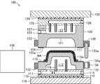
- ribs 161 for reinforcement are provided for the first molding part 111 and the second molding part 121 in the first cavity part 112 and the second cavity part 122. be able to. Thereby, thickness reduction can be achieved, ensuring the rigidity of the 1st molding part 111 and the 2nd molding part 121.
- one rib 161 is provided in each of the first molding part 111 and the second molding part 121, but the number and shape of the ribs 161 are formed in the first molding part 111 and the second molding part 121. Is determined as long as it can be supported.
- a fluid supply means was arranged.
- a temperature sensor for measuring the temperature of the first molding portion 111 and the second molding portion 121 is provided instead of or in addition to the cooling fluid supply means. It can also be provided.
- the temperature detected by the temperature sensor may be displayed on the operation panel 141, or may be used for heating control and cooling control of the first mold 110 and the second mold 120 by the control device 140. it can.
- the worker and the control device 140 can grasp the temperature conditions of the first molding unit 111 and the second molding unit 121, the temperatures of the first molding unit 111 and the second molding unit 121 are appropriately set.
- the molded product can be molded more efficiently and with high accuracy.
- the heat insulating insulators 113 and 124 are arranged on the first outer peripheral portion 110a and the second outer peripheral portion 120a in the first mold 110 and the second mold 120, respectively. These heat insulating insulators 113 and 124 electrically insulate and hold the outside of the molding region where the first mold 110 and the second mold 120 are closed, and electrically connect the first mold 110 and the second mold 120 to each other. It is for insulation. However, you may make it provide the heat insulation insulators 113 and 124 in order to exhibit at least 1 function of heat insulation, airtight maintenance, and electrical insulation.
- the heat insulating insulators 113 and 124 are It is not necessary to have an electrical insulation function.
- the heat insulating insulators 113 and 124 can be made of a material other than resin, for example, ceramic or concrete. The same applies to the heat insulating bases 118 and 128.
- connection electrodes 134 and 135 are configured such that the rod-shaped pin jacks 135 a protruding from the connection electrode 135 are fitted into the through holes 134 a formed in the connection electrode 134.
- the connection electrodes 134 and 135 are not limited to the above embodiment as long as the first and second molds 110 and 120 can be energized.
- the connection electrode 134 can be configured with a pantograph mechanism that expands and contracts toward the second mold 120, and the connection electrode 135 can be configured with an electrode that contacts the top of the pantograph mechanism.
- the power feeding device 136 is configured to supply an alternating current to the first mold 110 and the second mold 120.
- the power feeding device 136 may be configured to supply a direct current to the first mold 110 and the second mold 120.
- the 1st molding part 111 and the 2nd molding part 121 are formed thinner than the thickness of the 1st perimeter part 110a and the 2nd perimeter part 120a, ie, the cross-sectional area is formed small, electric resistance is formed. While being larger than the first outer peripheral portion 110a and the second outer peripheral portion 120a, the volume to be heated is small. Thereby, the 1st molding part 111 and the 2nd molding part 121 are heated early and efficiently.
- the amount of electricity output from the power supply device 136 is appropriately set according to the type, size, or molding accuracy of the material to be molded, and is not limited to the above embodiment.
- electricity is supplied to the first mold 110 and the second mold 120 by the single power supply device 136 and the connecting electrodes 134 and 135.
- a configuration may be adopted in which power is supplied individually from the single power supply device 136 to the first mold 110 and the second mold 120, and power is supplied to the first mold 110 and the second mold 120, respectively. It is also possible to prepare each of the power feeding devices 136 individually.
- a polyethylene resin is used as the molding material WK.
- the material to be molded WK is appropriately selected according to the specification of the product PR, and naturally other thermoplastic resins may be used.
- Polyetherimide resin polyether sulfone resin, polyphenylene sulfide resin, polysulfone resin, or polyether ether ketone resin can be used as the molding material WK.
- the material to be molded WK is composed of a thermoplastic resin sheet and a fiber sheet.
- the material to be molded WK is appropriately selected according to the specifications of the product PR. Therefore, the material to be molded WK may be composed of only a thermoplastic resin sheet, or may be composed of a thermoplastic resin plate that is thicker than the thermoplastic resin sheet.
- the molding material WK may be a fluid obtained by heating a thermoplastic resin. That is, the molding apparatus 100 according to the present invention can also be implemented as an injection molding machine.
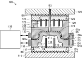
- a sprue 162 that forms a flow path of the molding material WK is formed at the center of the first mold 110.
- the first mold 110 and the second mold 120 are preheated before the molding material WK is injected, so that molding at the time of injection molding is performed. It is possible to effectively prevent so-called weld defects and so-called sink defects, and to make the product PR thinner. Also, a high melting point material such as polyether ether ketone resin can be injection molded with high accuracy.
- a movable mold in which a first mold 110 is mounted on a movable plate (not shown), and a second mold 120 is a fixed plate (not shown).
- the first mold 110 is displaced in a direction in which the first mold 110 approaches or separates from the fixed second mold 120.
- thermosetting resin such as a phenol resin, a melamine resin, a urea resin, a polyurethane resin, an epoxy resin is used. Resins or unsaturated polyester resins can also be used.
- injection molding can be performed using a mixture of these thermoplastic resins or thermosetting resins with carbon fibers, glass fibers, metal fibers, metal powders, or various mineral powders.
- the product PR can be molded by the following steps 1 to 6, for example. That is, Step 1: Clamping step for bringing first mold 110 and second mold 120 into close contact Step 2: Preheating step for energizing and heating first mold 110 and second mold 120 Step 3: Melting resin Injection process for injection into the mold through the sprue 162 (in this case, both energized and non-energized are possible) Step 4: Cooling step of supplying cooling water to the first die 110 and the second die 120 and cooling Step 5: Mold opening step of separating the first die 110 and the second die 120 Step 6: Ejector Taking out the product PR from the first mold 110 by driving the pins
- the molding apparatus 100 can be implemented as an injection molding machine or a press machine using a metal material.
- the molding material WK disposed in the first mold 110 and the second mold 120 can be heated, so the molding material WK is pressed. It is not necessary to heat in advance before placing it on the machine, reducing the work burden in the machining process, and accurately and efficiently press forming of steel materials that are difficult to plastically deform, specifically high strength steel. Can be done.
- the die face 163 is a steel plate member that passes through the first mold 110 and is slidably supported in a vertical direction in the figure by a support part (not shown) in the molding apparatus 100.
- the die face 163 is pushed by the outer peripheral portion 120a of the second mold 120 according to the displacement of the second mold 120 toward the first mold 110, and clamps the molding material WK on the first mold 110. .
- a material that is relatively easily plastically deformed such as a titanium material, an aluminum material, or a magnesium material
- the product PR can be molded by the following steps 1 to 6. That is, Step 1: Preheating step of energizing and heating the first mold 110 and the second mold 120 Step 2: The molding material WK in a mold open state in which the first mold 110 and the second mold 120 are separated from each other Material placement step 3 for setting the pressure: Pressurizing step (non-energization) for pressurizing in a clamped state in which the first mold 110 and the second mold 120 are in close contact with each other Step 4: Cooling step of supplying cooling water to the first die 110 and the second die 120 and cooling Step 5: Mold opening step of separating the first die 110 and the second die 120 Step 6: Ejector Taking out the product PR from the first mold 110 by driving the pins
- 2nd cavity part 123 ... Drain hole, 124 ... Thermal insulation insulator, 124a ... Base part, 124b ... Seal 125, receiving plate, 126 ... water supply hole, 127 ... fountain pipe, 128 ... heat insulation insulating base, 129 ... mounting plate, 131 ... Supply valve, 132, 133 ... Input / output electrode, 134, 135 ... Connection electrode, 134a ... Through hole, 135a ... Pin jack, 136 ... Power feeding device, 140 ... control device, 141 ... operation panel, 151 ... Mold driving device, 152 ... Vacuum device, 161 ... ribs, 162 ... sprue, 163 ... die face.
Landscapes
- Engineering & Computer Science (AREA)
- Mechanical Engineering (AREA)
- Manufacturing & Machinery (AREA)
- Moulds For Moulding Plastics Or The Like (AREA)
Abstract
Description
成型装置100は、第1金型110および第2金型120を備えている。第1金型110および第2金型120は、互いに協働して被成型材料の成型加工を行う鋼製の型であり、互いに対向する面の中央部に第1成型部111および第2成型部121がそれぞれ形成されている。第1成型部111および第2成型部121は、実際に被成型材料に熱および圧縮力を加えて成型加工を行う部分であり、製品PRの表面形状に対応する3次元形状、より具体的には、製品PRの表面の3次元形状を反転させた3次元形状にそれぞれ形成されている。
次に、このように構成した成型装置100の作動について説明する。まず、作業者は、図4に示すように、製品PRの原料となる被成型材料WKを用意する。本実施形態においては、2枚の熱可塑性樹脂製シート(例えば、ポリエチレン樹脂製シート)と1枚の繊維シート(例えば、ガラス繊維シート、炭素繊維シートまたは金属繊維シートなど)とをそれぞれ用意する。次に、作業者は、成型装置100を起動させる。具体的には、作業者は、成型装置100の操作パネル141を操作して成型装置100の電源を入れる。これにより、成型装置100の制御装置140は、図示しない所定の制御プログラムを実行することにより作業者からの指令の入力を待つ待機状態となる。
工程1:第1金型110と第2金型120とを密着させる型締め工程
工程2:第1金型110および第2金型120に通電して加熱する予備加熱工程
工程3:溶融樹脂をスプル162を介して金型内に注入する注入工程(この場合、通電しても非通電であってもともに可)
工程4:第1金型110および第2金型120に冷却水を供給して冷却する冷却工程
工程5:第1金型110と第2金型120とを離隔させる型開き工程
工程6:エジェクタピンを駆動して製品PRを第1金型110から取り出す取出し工程
工程1:第1金型110および第2金型120に通電して加熱する予備加熱工程
工程2:第1金型110と第2金型120とを離隔させた型開き状態で被成型材料WKをセットする材料配置工程
工程3:第1金型110と第2金型120とを密着させた型締め状態で加圧する加圧工程(非通電)
工程4:第1金型110および第2金型120に冷却水を供給して冷却する冷却工程
工程5:第1金型110と第2金型120とを離隔させる型開き工程
工程6:エジェクタピンを駆動して製品PRを第1金型110から取り出す取出し工程
100…成型装置、
110…第1金型、110a…第1外周部、111…第1成型部、112…第1空洞部、113…断熱絶縁体、113a・・・基部、113b…シール部、114…受け板、115…給水穴、116…噴水パイプ、117…排水穴、118…断熱絶縁ベース、119…取付板、
120…第2金型、120a…第2外周部、121…第2成型部、122…第2空洞部、123・・・排水穴、124…断熱絶縁体、124a・・・基部、124b…シール部、125…受け板、126…給水穴、127…噴水パイプ、128…断熱絶縁ベース、129…取付板、
131…供給弁、132,133…入出力電極、134,135…連結電極、134a…貫通孔、135a…ピンジャック、136…給電装置、
140…制御装置、141…操作パネル、
151…金型駆動装置、152…バキューム装置、
161…リブ、162…スプル、163…ダイフェース。
Claims (9)
- 成型対象となる製品の表面の一部に対応する3次元形状に形成された第1成型部を有する第1金型と、
前記製品の表面の他の一部に対応する3次元形状に形成された第2成型部を有して前記第1金型に対向配置される第2金型とを備え、
前記第1成型部と前記第2成型部との間に被成型材料を配置して前記製品を成型する成型装置において、
前記第1金型および前記第2金型のうちの少なくとも一方に電気を流すための金型通電手段を備え、
前記第1金型および/または前記第2金型は、
前記通電される前記第1成型部および/または前記第2成型部の肉厚が同第1成型部および/または第2成型部の周囲に形成されて同第1成型部および/または同第2成型部を支持する外周部の肉厚より薄肉に形成されていることを特徴とする成型装置。 - 請求項1に記載した成型装置において、
前記第1金型および/または前記第2金型は、
前記薄肉に形成された前記第1成型部および/または前記第2成型部の裏側に前記第1成型部および/または前記第2成型部に沿って空洞部が形成されていることを特徴とする成型装置。 - 請求項2に記載した成型装置において、さらに、
前記空洞部に、前記第1成型部および/または前記第2成型部に対して冷却用流体を供給する冷却流体供給手段を設けたことを特徴とする成型装置。 - 請求項2または請求項3に記載した成型装置において、さらに、
前記空洞部に、前記第1成型部および/または前記第2成型部を支えるリブを設けたことを特徴とする成型装置。 - 請求項2ないし請求項4のうちのいずれか1つに記載した成型装置において、さらに、
前記空洞部に、前記第1成型部および/または前記第2成型部の温度を測定するための温度測定センサを設けたことを特徴とする成型装置。 - 請求項1ないし請求項5のうちのいずれか1つに記載した成型装置において、
前記金型通電手段は、
前記第1金型と前記第2金型とを電気的に接続および切断する電気接続部を備えることを特徴とする成型装置。 - 請求項1ないし請求項6のうちのいずれか1つに記載した成型装置において、
前記第1金型と前記第2金型との間における前記外周部に絶縁体を設けたことを特徴とする成型装置。 - 成型対象となる製品の表面の一部に対応する3次元形状に形成された第1成型部を有する第1金型と、
前記製品の表面の他の一部に対応する3次元形状に形成された第2成型部を有して前記第1金型に対向配置される第2金型とを備え、
前記第1成型部と前記第2成型部との間に被成型材料を配置して前記製品を成型する成型方法において、
前記第1成型部および前記第2成型部のうちの少なくとも一方の肉厚を同第1成型部および/または第2成型部の周囲に形成されて同第1成型部および/または同第2成型部を支持する外周部の肉厚より薄肉に形成しておき、
前記薄肉に形成した前記第1成型部および/または前記第2成型部が形成された前記第1金型および/または前記第2金型に電気を流すことにより前記第1成型部および/または前記第2成型部を加熱し、
前記加熱された前記第1成型部および/または前記第2成型部によって前記被成型素材を前記製品に成型することを特徴とする成型方法。 - 請求項8に記載した成型方法において、
前記第1金型および/または前記第2金型における前記第1成型部および/または前記第2成型部の裏側に、前記第1成型部および/または前記第2成型部に沿って空洞部を形成しておくとともに、同空洞部に対向して前記第1成型部および/または前記第2成型部に対して冷却用流体を供給する冷却流体供給手段を設けておき、
前記被成型材料の成型後に、前記冷却流体供給手段から前記冷却用流体を前記第1成型部および/または前記第2成型部に対して供給して前記第1成型部および/または前記第2成型部を冷却することを特徴とする成型方法。
Priority Applications (4)
| Application Number | Priority Date | Filing Date | Title |
|---|---|---|---|
| CN201180060907.1A CN103269838B (zh) | 2010-12-24 | 2011-12-21 | 成型装置及利用该成型装置进行成型的成型方法 |
| US13/261,673 US9738022B2 (en) | 2010-12-24 | 2011-12-21 | Molding device and molding method using the molding device |
| KR1020127017790A KR101252730B1 (ko) | 2010-12-24 | 2011-12-21 | 성형장치 및 동 성형장치에 의한 성형방법 |
| EP11851450.4A EP2656992B1 (en) | 2010-12-24 | 2011-12-21 | Molding device and molding method by the molding device |
Applications Claiming Priority (2)
| Application Number | Priority Date | Filing Date | Title |
|---|---|---|---|
| JP2010288977A JP5107417B2 (ja) | 2010-12-24 | 2010-12-24 | 成型装置および同成型装置による成型方法 |
| JP2010-288977 | 2010-12-24 |
Publications (1)
| Publication Number | Publication Date |
|---|---|
| WO2012086675A1 true WO2012086675A1 (ja) | 2012-06-28 |
Family
ID=46313943
Family Applications (1)
| Application Number | Title | Priority Date | Filing Date |
|---|---|---|---|
| PCT/JP2011/079610 Ceased WO2012086675A1 (ja) | 2010-12-24 | 2011-12-21 | 成型装置および同成型装置による成型方法 |
Country Status (6)
| Country | Link |
|---|---|
| US (1) | US9738022B2 (ja) |
| EP (1) | EP2656992B1 (ja) |
| JP (1) | JP5107417B2 (ja) |
| KR (1) | KR101252730B1 (ja) |
| CN (1) | CN103269838B (ja) |
| WO (1) | WO2012086675A1 (ja) |
Families Citing this family (13)
| Publication number | Priority date | Publication date | Assignee | Title |
|---|---|---|---|---|
| WO2010104129A1 (ja) * | 2009-03-12 | 2010-09-16 | 学校法人同志社 | 樹脂成形装置及び樹脂成形方法 |
| JP5740183B2 (ja) * | 2011-03-15 | 2015-06-24 | ジヤトコ株式会社 | 鋳造用金型 |
| IN2014DN10743A (ja) | 2012-06-19 | 2015-09-04 | Roctool | |
| KR102130735B1 (ko) * | 2014-09-03 | 2020-07-06 | 삼성전자주식회사 | 디스플레이장치 |
| CN104498937B (zh) * | 2014-11-25 | 2017-05-17 | 张家港市华地机械装备有限公司 | 升温型金属材料低压加工设备 |
| JP2016147377A (ja) * | 2015-02-10 | 2016-08-18 | 株式会社キャップ | Frp製品の成型方法およびfrp製品の製造方法 |
| CN104741547B (zh) * | 2015-04-01 | 2017-01-11 | 无锡蠡湖增压技术股份有限公司 | 一种带热碰模的压气壳用无砂芯金属模具 |
| JP6323487B2 (ja) * | 2016-03-31 | 2018-05-16 | マツダ株式会社 | 射出成形装置および射出成形方法 |
| US10946592B2 (en) * | 2016-09-11 | 2021-03-16 | Impossible Objects, Inc. | Resistive heating-compression method and apparatus for composite-based additive manufacturing |
| KR200492455Y1 (ko) * | 2017-10-10 | 2020-10-16 | 쥔 허 테크놀로지 컴퍼니 리미티드 | 광학시트 사출성형 모듈 구조 |
| CN112974764B (zh) * | 2021-02-07 | 2022-08-30 | 深圳市新联兴精密压铸有限公司 | 一种耐用型手机中板成型模具 |
| CN113477911B (zh) * | 2021-06-29 | 2023-02-21 | 江苏苏美达铝业有限公司 | 一种高效自动化重力铸造轮毂生产装置 |
| CN115476480A (zh) * | 2022-09-14 | 2022-12-16 | 龚彪 | 一种汽车保险杠的内分型模具 |
Citations (11)
| Publication number | Priority date | Publication date | Assignee | Title |
|---|---|---|---|---|
| JPS574748A (en) | 1980-06-11 | 1982-01-11 | Asahi Chem Ind Co Ltd | Injection molding equipment |
| JPS59109310A (ja) * | 1982-12-15 | 1984-06-25 | Royal Kogyo Kk | 成形方法及び成形機 |
| JPH0433809A (ja) * | 1990-05-30 | 1992-02-05 | Ibiden Co Ltd | プラスチック成形装置 |
| JPH04197722A (ja) * | 1990-11-29 | 1992-07-17 | Japan Steel Works Ltd:The | プラスチック成形金型における加熱冷却方法及び装置 |
| JPH04265720A (ja) | 1991-02-20 | 1992-09-21 | Taiho Kogyo Kk | 表面加熱成形金型 |
| JPH09123240A (ja) | 1995-11-07 | 1997-05-13 | Sony Corp | 射出成形方法及び装置 |
| JPH10217252A (ja) * | 1996-12-03 | 1998-08-18 | Nissei Kk | 澱粉製生分解性成形物の製造方法 |
| JPH11348041A (ja) | 1998-06-08 | 1999-12-21 | Ono Sangyo Kk | 合成樹脂成形用金型およびその加熱・冷却方法 |
| JP2007118213A (ja) | 2005-10-25 | 2007-05-17 | Yamashita Denki Kk | 合成樹脂成形用金型 |
| JP2007535786A (ja) | 2004-03-18 | 2007-12-06 | ロックツール | 物体を生産するため材料を加熱する方法および前記方法を実装するデバイス |
| JP2009202348A (ja) | 2008-02-26 | 2009-09-10 | Panasonic Corp | 金型装置 |
Family Cites Families (12)
| Publication number | Priority date | Publication date | Assignee | Title |
|---|---|---|---|---|
| US2801442A (en) * | 1954-08-02 | 1957-08-06 | Ernest P Moslo | Molding machine die protection means |
| US5591491A (en) * | 1994-02-04 | 1997-01-07 | Nissei Kabushiki Kaisha | Method for manufacturing biodegradable molded articles |
| AUPM802794A0 (en) * | 1994-09-09 | 1994-10-06 | Graham, Neil | Improved method of manufacturing composites |
| US6048189A (en) * | 1995-04-05 | 2000-04-11 | Japan Synthetic Rubber Co., Ltd. | Blow molding apparatus |
| JP2795216B2 (ja) * | 1995-04-06 | 1998-09-10 | ジェイエスアール株式会社 | 成形用金型、成形方法、成形材料、及び成形品 |
| EP0909626A3 (en) * | 1997-10-17 | 2000-02-02 | TOHOKU MUNEKATA Co., Ltd. | Method and apparatus for injection moulding plastics |
| JP2003191264A (ja) * | 2001-12-27 | 2003-07-08 | Nissei Co Ltd | 生分解性成形物の製造方法 |
| CN1301222C (zh) * | 2003-04-28 | 2007-02-21 | Hoya株式会社 | 压模成形设备、压模成形方法以及制造光学元件的方法 |
| CN2770927Y (zh) * | 2005-03-29 | 2006-04-12 | 重庆工学院 | 高强聚乙烯纤维防弹头盔成型模具 |
| KR100792077B1 (ko) * | 2006-05-16 | 2008-01-04 | 엘지전자 주식회사 | 금형장치 |
| TWI415729B (zh) * | 2009-02-27 | 2013-11-21 | 私立中原大學 | Mold with the uniform heating and cooling structure |
| WO2010104129A1 (ja) * | 2009-03-12 | 2010-09-16 | 学校法人同志社 | 樹脂成形装置及び樹脂成形方法 |
-
2010
- 2010-12-24 JP JP2010288977A patent/JP5107417B2/ja not_active Expired - Fee Related
-
2011
- 2011-12-21 US US13/261,673 patent/US9738022B2/en not_active Expired - Fee Related
- 2011-12-21 CN CN201180060907.1A patent/CN103269838B/zh not_active Expired - Fee Related
- 2011-12-21 WO PCT/JP2011/079610 patent/WO2012086675A1/ja not_active Ceased
- 2011-12-21 KR KR1020127017790A patent/KR101252730B1/ko not_active Expired - Fee Related
- 2011-12-21 EP EP11851450.4A patent/EP2656992B1/en not_active Not-in-force
Patent Citations (11)
| Publication number | Priority date | Publication date | Assignee | Title |
|---|---|---|---|---|
| JPS574748A (en) | 1980-06-11 | 1982-01-11 | Asahi Chem Ind Co Ltd | Injection molding equipment |
| JPS59109310A (ja) * | 1982-12-15 | 1984-06-25 | Royal Kogyo Kk | 成形方法及び成形機 |
| JPH0433809A (ja) * | 1990-05-30 | 1992-02-05 | Ibiden Co Ltd | プラスチック成形装置 |
| JPH04197722A (ja) * | 1990-11-29 | 1992-07-17 | Japan Steel Works Ltd:The | プラスチック成形金型における加熱冷却方法及び装置 |
| JPH04265720A (ja) | 1991-02-20 | 1992-09-21 | Taiho Kogyo Kk | 表面加熱成形金型 |
| JPH09123240A (ja) | 1995-11-07 | 1997-05-13 | Sony Corp | 射出成形方法及び装置 |
| JPH10217252A (ja) * | 1996-12-03 | 1998-08-18 | Nissei Kk | 澱粉製生分解性成形物の製造方法 |
| JPH11348041A (ja) | 1998-06-08 | 1999-12-21 | Ono Sangyo Kk | 合成樹脂成形用金型およびその加熱・冷却方法 |
| JP2007535786A (ja) | 2004-03-18 | 2007-12-06 | ロックツール | 物体を生産するため材料を加熱する方法および前記方法を実装するデバイス |
| JP2007118213A (ja) | 2005-10-25 | 2007-05-17 | Yamashita Denki Kk | 合成樹脂成形用金型 |
| JP2009202348A (ja) | 2008-02-26 | 2009-09-10 | Panasonic Corp | 金型装置 |
Non-Patent Citations (1)
| Title |
|---|
| See also references of EP2656992A4 * |
Also Published As
| Publication number | Publication date |
|---|---|
| US9738022B2 (en) | 2017-08-22 |
| CN103269838B (zh) | 2015-07-15 |
| KR101252730B1 (ko) | 2013-04-10 |
| JP2012135915A (ja) | 2012-07-19 |
| CN103269838A (zh) | 2013-08-28 |
| US20130334741A1 (en) | 2013-12-19 |
| KR20120097532A (ko) | 2012-09-04 |
| EP2656992A1 (en) | 2013-10-30 |
| EP2656992B1 (en) | 2015-10-14 |
| JP5107417B2 (ja) | 2012-12-26 |
| EP2656992A4 (en) | 2014-09-03 |
Similar Documents
| Publication | Publication Date | Title |
|---|---|---|
| JP5107417B2 (ja) | 成型装置および同成型装置による成型方法 | |
| CN114953511B (zh) | 一种碳纤维增强热塑性复合材料-金属复合构件的快速成型方法与装置 | |
| CN205148946U (zh) | 纤维增强热塑性树脂基复合材料层板模压装置 | |
| EP3785890B1 (en) | System, preform shaping method and composite material molding method | |
| WO2010104129A1 (ja) | 樹脂成形装置及び樹脂成形方法 | |
| CN113939396B (zh) | 纤维强化树脂材料的成型品制造装置以及成型品的制造方法 | |
| JP6021256B2 (ja) | 繊維複合成形品のプレス成形方法、繊維複合成形品のプレス成形装置、および繊維複合成形品の金型 | |
| JP6578030B2 (ja) | 強化繊維と熱可塑性樹脂を含む成形品のプレス成形方法 | |
| WO2017010266A1 (ja) | 成型装置 | |
| JP2017222142A (ja) | 強化繊維と熱可塑性樹脂を含む成形品のプレス成形装置およびプレス成形方法 | |
| CN102308667A (zh) | 用于生产复合材料制成的零件的柔性薄膜 | |
| JP5703486B2 (ja) | 成型装置および同成型装置による成型方法 | |
| CN113370441A (zh) | 一种碳纤维金属层板及其热冲压成形方法 | |
| CN112976606A (zh) | 一种碳纤维增强热塑性复合材料结构件的成型模具、热压成型系统及成型方法 | |
| CN113891794B (zh) | 纤维强化树脂材料的成型品制造装置以及成型品的制造方法 | |
| CN115383954A (zh) | 模压成型装置及方法 | |
| JP2018505073A (ja) | モールド及びプラスチックシートを成型する方法 | |
| CN107052123B (zh) | 一种金属管类零件热态金属气压成型方法 | |
| JP2011104961A (ja) | 成形同時転写用金型及び成形同時転写品の製造方法 | |
| CN117901338A (zh) | 一种用于钢丝管管端密封的装置及方法 | |
| WO2016129566A1 (ja) | Frp製品の成型方法およびfrp製品の製造方法 | |
| CN112672836A (zh) | 带有导热凸缘的模具 | |
| CN121733751A (zh) | 一种用于电缆附件生产的加工设备及电缆附件的制备方法 | |
| JP2016147377A5 (ja) | ||
| JP2005335194A (ja) | バルブ装置及びその製造方法 |
Legal Events
| Date | Code | Title | Description |
|---|---|---|---|
| ENP | Entry into the national phase |
Ref document number: 20127017790 Country of ref document: KR Kind code of ref document: A |
|
| 121 | Ep: the epo has been informed by wipo that ep was designated in this application |
Ref document number: 11851450 Country of ref document: EP Kind code of ref document: A1 |
|
| NENP | Non-entry into the national phase |
Ref country code: DE |
|
| WWE | Wipo information: entry into national phase |
Ref document number: 2011851450 Country of ref document: EP |
|
| WWE | Wipo information: entry into national phase |
Ref document number: 13261673 Country of ref document: US |