WO2012086748A1 - 金属酸化物微粒子含有膜、転写フィルムおよびその製造方法並びに積層体およびその製造方法 - Google Patents
金属酸化物微粒子含有膜、転写フィルムおよびその製造方法並びに積層体およびその製造方法 Download PDFInfo
- Publication number
- WO2012086748A1 WO2012086748A1 PCT/JP2011/079796 JP2011079796W WO2012086748A1 WO 2012086748 A1 WO2012086748 A1 WO 2012086748A1 JP 2011079796 W JP2011079796 W JP 2011079796W WO 2012086748 A1 WO2012086748 A1 WO 2012086748A1
- Authority
- WO
- WIPO (PCT)
- Prior art keywords
- film
- refractive index
- laminate
- composition
- metal oxide
- Prior art date
- Legal status (The legal status is an assumption and is not a legal conclusion. Google has not performed a legal analysis and makes no representation as to the accuracy of the status listed.)
- Ceased
Links
Images
Classifications
-
- G—PHYSICS
- G02—OPTICS
- G02B—OPTICAL ELEMENTS, SYSTEMS OR APPARATUS
- G02B1/00—Optical elements characterised by the material of which they are made; Optical coatings for optical elements
- G02B1/10—Optical coatings produced by application to, or surface treatment of, optical elements
- G02B1/11—Anti-reflection coatings
- G02B1/111—Anti-reflection coatings using layers comprising organic materials
-
- C—CHEMISTRY; METALLURGY
- C08—ORGANIC MACROMOLECULAR COMPOUNDS; THEIR PREPARATION OR CHEMICAL WORKING-UP; COMPOSITIONS BASED THEREON
- C08F—MACROMOLECULAR COMPOUNDS OBTAINED BY REACTIONS ONLY INVOLVING CARBON-TO-CARBON UNSATURATED BONDS
- C08F283/00—Macromolecular compounds obtained by polymerising monomers on to polymers provided for in subclass C08G
- C08F283/12—Macromolecular compounds obtained by polymerising monomers on to polymers provided for in subclass C08G on to polysiloxanes
-
- C—CHEMISTRY; METALLURGY
- C08—ORGANIC MACROMOLECULAR COMPOUNDS; THEIR PREPARATION OR CHEMICAL WORKING-UP; COMPOSITIONS BASED THEREON
- C08F—MACROMOLECULAR COMPOUNDS OBTAINED BY REACTIONS ONLY INVOLVING CARBON-TO-CARBON UNSATURATED BONDS
- C08F290/00—Macromolecular compounds obtained by polymerising monomers on to polymers modified by introduction of aliphatic unsaturated end or side groups
- C08F290/02—Macromolecular compounds obtained by polymerising monomers on to polymers modified by introduction of aliphatic unsaturated end or side groups on to polymers modified by introduction of unsaturated end groups
- C08F290/06—Polymers provided for in subclass C08G
- C08F290/062—Polyethers
-
- C—CHEMISTRY; METALLURGY
- C08—ORGANIC MACROMOLECULAR COMPOUNDS; THEIR PREPARATION OR CHEMICAL WORKING-UP; COMPOSITIONS BASED THEREON
- C08F—MACROMOLECULAR COMPOUNDS OBTAINED BY REACTIONS ONLY INVOLVING CARBON-TO-CARBON UNSATURATED BONDS
- C08F292/00—Macromolecular compounds obtained by polymerising monomers on to inorganic materials
-
- C—CHEMISTRY; METALLURGY
- C08—ORGANIC MACROMOLECULAR COMPOUNDS; THEIR PREPARATION OR CHEMICAL WORKING-UP; COMPOSITIONS BASED THEREON
- C08G—MACROMOLECULAR COMPOUNDS OBTAINED OTHERWISE THAN BY REACTIONS ONLY INVOLVING UNSATURATED CARBON-TO-CARBON BONDS
- C08G65/00—Macromolecular compounds obtained by reactions forming an ether link in the main chain of the macromolecule
- C08G65/002—Macromolecular compounds obtained by reactions forming an ether link in the main chain of the macromolecule from unsaturated compounds
- C08G65/005—Macromolecular compounds obtained by reactions forming an ether link in the main chain of the macromolecule from unsaturated compounds containing halogens
- C08G65/007—Macromolecular compounds obtained by reactions forming an ether link in the main chain of the macromolecule from unsaturated compounds containing halogens containing fluorine
-
- C—CHEMISTRY; METALLURGY
- C09—DYES; PAINTS; POLISHES; NATURAL RESINS; ADHESIVES; COMPOSITIONS NOT OTHERWISE PROVIDED FOR; APPLICATIONS OF MATERIALS NOT OTHERWISE PROVIDED FOR
- C09D—COATING COMPOSITIONS, e.g. PAINTS, VARNISHES OR LACQUERS; FILLING PASTES; CHEMICAL PAINT OR INK REMOVERS; INKS; CORRECTING FLUIDS; WOODSTAINS; PASTES OR SOLIDS FOR COLOURING OR PRINTING; USE OF MATERIALS THEREFOR
- C09D151/00—Coating compositions based on graft polymers in which the grafted component is obtained by reactions only involving carbon-to-carbon unsaturated bonds; Coating compositions based on derivatives of such polymers
- C09D151/08—Coating compositions based on graft polymers in which the grafted component is obtained by reactions only involving carbon-to-carbon unsaturated bonds; Coating compositions based on derivatives of such polymers grafted on to macromolecular compounds obtained otherwise than by reactions only involving carbon-to-carbon unsaturated bonds
- C09D151/085—Coating compositions based on graft polymers in which the grafted component is obtained by reactions only involving carbon-to-carbon unsaturated bonds; Coating compositions based on derivatives of such polymers grafted on to macromolecular compounds obtained otherwise than by reactions only involving carbon-to-carbon unsaturated bonds on to polysiloxanes
-
- C—CHEMISTRY; METALLURGY
- C09—DYES; PAINTS; POLISHES; NATURAL RESINS; ADHESIVES; COMPOSITIONS NOT OTHERWISE PROVIDED FOR; APPLICATIONS OF MATERIALS NOT OTHERWISE PROVIDED FOR
- C09D—COATING COMPOSITIONS, e.g. PAINTS, VARNISHES OR LACQUERS; FILLING PASTES; CHEMICAL PAINT OR INK REMOVERS; INKS; CORRECTING FLUIDS; WOODSTAINS; PASTES OR SOLIDS FOR COLOURING OR PRINTING; USE OF MATERIALS THEREFOR
- C09D151/00—Coating compositions based on graft polymers in which the grafted component is obtained by reactions only involving carbon-to-carbon unsaturated bonds; Coating compositions based on derivatives of such polymers
- C09D151/10—Coating compositions based on graft polymers in which the grafted component is obtained by reactions only involving carbon-to-carbon unsaturated bonds; Coating compositions based on derivatives of such polymers grafted on to inorganic materials
-
- C—CHEMISTRY; METALLURGY
- C09—DYES; PAINTS; POLISHES; NATURAL RESINS; ADHESIVES; COMPOSITIONS NOT OTHERWISE PROVIDED FOR; APPLICATIONS OF MATERIALS NOT OTHERWISE PROVIDED FOR
- C09D—COATING COMPOSITIONS, e.g. PAINTS, VARNISHES OR LACQUERS; FILLING PASTES; CHEMICAL PAINT OR INK REMOVERS; INKS; CORRECTING FLUIDS; WOODSTAINS; PASTES OR SOLIDS FOR COLOURING OR PRINTING; USE OF MATERIALS THEREFOR
- C09D171/00—Coating compositions based on polyethers obtained by reactions forming an ether link in the main chain; Coating compositions based on derivatives of such polymers
-
- C—CHEMISTRY; METALLURGY
- C09—DYES; PAINTS; POLISHES; NATURAL RESINS; ADHESIVES; COMPOSITIONS NOT OTHERWISE PROVIDED FOR; APPLICATIONS OF MATERIALS NOT OTHERWISE PROVIDED FOR
- C09J—ADHESIVES; NON-MECHANICAL ASPECTS OF ADHESIVE PROCESSES IN GENERAL; ADHESIVE PROCESSES NOT PROVIDED FOR ELSEWHERE; USE OF MATERIALS AS ADHESIVES
- C09J171/00—Adhesives based on polyethers obtained by reactions forming an ether link in the main chain; Adhesives based on derivatives of such polymers
-
- G—PHYSICS
- G02—OPTICS
- G02B—OPTICAL ELEMENTS, SYSTEMS OR APPARATUS
- G02B1/00—Optical elements characterised by the material of which they are made; Optical coatings for optical elements
- G02B1/10—Optical coatings produced by application to, or surface treatment of, optical elements
- G02B1/11—Anti-reflection coatings
- G02B1/118—Anti-reflection coatings having sub-optical wavelength surface structures designed to provide an enhanced transmittance, e.g. moth-eye structures
-
- G—PHYSICS
- G02—OPTICS
- G02B—OPTICAL ELEMENTS, SYSTEMS OR APPARATUS
- G02B1/00—Optical elements characterised by the material of which they are made; Optical coatings for optical elements
- G02B1/10—Optical coatings produced by application to, or surface treatment of, optical elements
- G02B1/18—Coatings for keeping optical surfaces clean, e.g. hydrophobic or photo-catalytic films
-
- C—CHEMISTRY; METALLURGY
- C08—ORGANIC MACROMOLECULAR COMPOUNDS; THEIR PREPARATION OR CHEMICAL WORKING-UP; COMPOSITIONS BASED THEREON
- C08G—MACROMOLECULAR COMPOUNDS OBTAINED OTHERWISE THAN BY REACTIONS ONLY INVOLVING UNSATURATED CARBON-TO-CARBON BONDS
- C08G2650/00—Macromolecular compounds obtained by reactions forming an ether link in the main chain of the macromolecule
- C08G2650/28—Macromolecular compounds obtained by reactions forming an ether link in the main chain of the macromolecule characterised by the polymer type
- C08G2650/46—Macromolecular compounds obtained by reactions forming an ether link in the main chain of the macromolecule characterised by the polymer type containing halogen
- C08G2650/48—Macromolecular compounds obtained by reactions forming an ether link in the main chain of the macromolecule characterised by the polymer type containing halogen containing fluorine, e.g. perfluropolyethers
-
- Y—GENERAL TAGGING OF NEW TECHNOLOGICAL DEVELOPMENTS; GENERAL TAGGING OF CROSS-SECTIONAL TECHNOLOGIES SPANNING OVER SEVERAL SECTIONS OF THE IPC; TECHNICAL SUBJECTS COVERED BY FORMER USPC CROSS-REFERENCE ART COLLECTIONS [XRACs] AND DIGESTS
- Y10—TECHNICAL SUBJECTS COVERED BY FORMER USPC
- Y10T—TECHNICAL SUBJECTS COVERED BY FORMER US CLASSIFICATION
- Y10T156/00—Adhesive bonding and miscellaneous chemical manufacture
- Y10T156/10—Methods of surface bonding and/or assembly therefor
-
- Y—GENERAL TAGGING OF NEW TECHNOLOGICAL DEVELOPMENTS; GENERAL TAGGING OF CROSS-SECTIONAL TECHNOLOGIES SPANNING OVER SEVERAL SECTIONS OF THE IPC; TECHNICAL SUBJECTS COVERED BY FORMER USPC CROSS-REFERENCE ART COLLECTIONS [XRACs] AND DIGESTS
- Y10—TECHNICAL SUBJECTS COVERED BY FORMER USPC
- Y10T—TECHNICAL SUBJECTS COVERED BY FORMER US CLASSIFICATION
- Y10T428/00—Stock material or miscellaneous articles
- Y10T428/24—Structurally defined web or sheet [e.g., overall dimension, etc.]
- Y10T428/24355—Continuous and nonuniform or irregular surface on layer or component [e.g., roofing, etc.]
- Y10T428/24372—Particulate matter
- Y10T428/24413—Metal or metal compound
Definitions
- the present invention relates to a metal oxide fine particle-containing film, a transfer film, a manufacturing method thereof, a laminate, and a manufacturing method thereof.
- Transparent resins such as acrylic resins and polycarbonate resins are widely used as materials for industrial materials and construction materials. Particularly in recent years, it has been used as a front plate for displays such as CRTs, liquid crystal televisions, and plasma displays because of its transparency and impact resistance.
- the antireflection function is a function for reducing the reflected light of indoor fluorescent lamps and the like reflected on the front plate and displaying the image more clearly.
- a transfer film in which a low refractive index layer, a high refractive index layer and an adhesive layer are sequentially laminated on a process paper is arranged so that the surface of the adhesive layer is in contact with the surface of the peeling film.
- a peeling film in which a layer having an antireflection function is laminated on the surface by peeling the process paper after the lamination has been proposed (see Patent Document 1).
- an anti-smudge (anti-smudge) function is required on the surface of the antireflection layer.
- an antireflection transfer film in which a release layer, an antifouling functional layer, an antireflection layer, and an adhesive layer are sequentially laminated on one side of a plastic film.
- the release layer and the plastic film are peeled off to obtain a laminate in which an antireflection layer and an antifouling layer are sequentially laminated on the surface of the transfer object ( Patent Document 2).
- this laminate has a problem that if the refractive index difference between the high refractive index layer and the adhesive layer is large, reflection occurs at the interface between the high refractive index layer and the adhesive layer, an interference pattern is observed, and the appearance quality is impaired. It was.
- An object of the present invention is to provide a transfer film capable of obtaining a laminate having excellent antifouling properties, antireflection properties, transparency and sweat resistance, excellent scratch resistance, and suppressed interference patterns, and antifouling properties. It is to provide a laminate having excellent properties, antireflection properties, transparency and sweat resistance, excellent scratch resistance and suppressed interference patterns.
- an object of the present invention is to provide a metal oxide fine particle-containing film suitable for obtaining the transfer film and the laminate.
- a film central region in which no metal oxide fine particles are present a film surface layer region (a1) in which metal oxide fine particles are present on one side of the film central region, and a metal oxide fine particle on the other side of the film central region.
- a metal oxide fine particle-containing film in which a film surface layer region (a2) in which is present is formed (first invention).
- a low refractive index film having a refractive index (Nx), a high refractive index film having a refractive index (Ny), and a middle refractive index film having a refractive index (Nz) are arranged in this order on one side of the peeling film.
- the transfer films are laminated, and their refractive indices are measured with a wavelength of 594 nm laser, satisfy the following formula (5), and the medium refractive index film is a film containing the metal oxide fine particles.
- the present invention provides a metal oxide as a low refractive index film having a refractive index (Nx), a high refractive index film having a refractive index (Ny), and a middle refractive index film having a refractive index (Nz) on one surface of a peeling film.
- the fine particle-containing film is laminated in this order, and the refractive index is measured by a laser with a wavelength of 594 nm and is a method for producing a transfer film satisfying the above formula (5).
- a metal oxide comprising a high refractive index film after laminating a refractive index film, and then a dilution solvent containing 20% by mass or more of metal oxide fine particles and a solvent having a volatilization rate of 100 or less on the surface of the high refractive index film This is a transfer film manufacturing method in which a diluted solvent is dried at a temperature of 140 ° C. or less after applying the fine particle-containing film composition, and a medium refractive index film is laminated (third invention).
- the present invention is a laminate (A) in which the metal oxide fine particle-containing film is laminated on at least one surface of a base material directly or via another layer (fourth invention).
- the present invention provides a medium refractive index film having a refractive index (Nz), a high refractive index film having a refractive index (Ny), and a refractive index (Nx) directly or via another layer on at least one surface of a substrate.
- Nz refractive index
- Ny high refractive index film having a refractive index
- Nx refractive index directly or via another layer on at least one surface of a substrate.
- the refractive index is a laminate (B) measured by a laser with a wavelength of 594 nm and satisfying the above formula (5).
- This is a laminate (B) which is a metal oxide fine particle-containing film (fifth invention).
- the present invention is applied to the surface of the base material after applying the metal oxide fine particle-containing film composition containing the metal oxide fine particles and the dilution solvent containing 20% by mass or more of the dilution solvent having a volatilization rate of 100 or less to 140%. It is a manufacturing method of the said laminated body (A) which dries this dilution solvent at the temperature below degrees C, and laminate
- the present invention provides a medium refractive index film having a refractive index (Nz), a high refractive index film having a refractive index (Ny), and a refractive index (Nx) directly or via another layer on at least one surface of a substrate.
- Nz refractive index
- Ny high refractive index film having a refractive index
- Nx refractive index directly or via another layer on at least one surface of a substrate.
- the refractive index is a laminate (B) measured by a laser with a wavelength of 594 nm and satisfying the above formula (5).
- a laminate (A) having a metal oxide fine particle-containing film that can be adjusted to various refractive indexes on the surface and having excellent scratch resistance can be obtained.
- the laminate (A) is suitable for applications such as a front plate of equipment that requires antireflection properties.
- a laminate (B) excellent in antifouling property, antireflection property, transparency and sweat resistance, excellent in scratch resistance and having a suppressed interference pattern can be obtained.
- the laminate (B) is suitable as an image display member used outdoors, or as a front plate for cellular phones, portable information terminals, notebook personal computers, etc. to which fingerprints, sebum, foundations and the like are easily attached.
- MO fine particles The metal oxide fine particles (hereinafter referred to as “MO fine particles”) used in the present invention are contained in an MO fine particle-containing film described later.
- MO fine particles examples include tin oxide, tin oxide doped with antimony (ATO), indium oxide, tin doped indium oxide (ITO), zinc oxide, aluminum doped zinc oxide, zinc antimonate, and antimony pentoxide. Is mentioned.
- MO fine particles those obtained by individually treating the particle surface with a surface treating agent such as a hydrolyzable silane compound can be used according to the purpose.
- Individual treatment means that the MO fine particles are reacted only with a surface treatment agent such as a hydrolyzable silane compound, and does not contain compounds other than catalysts that contribute to hydrolysis and condensation reactions of acids and bases. This means that the surface of the MO fine particles is treated.
- the mixing ratio when the hydrolyzable silane compound is reacted with the surface of the MO fine particle is the sum of the hydrolyzable silane compound and the MO fine particle in terms of scratch resistance and antireflection performance of the surface of the laminate.
- the MO fine particles are preferably 20 to 80% by mass.
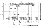
- the film central region is a region combining Tb1 and Tc1, which is the central region of the MO fine particle-containing film, a region combining Tb2 and Tc2, and a region including Tbi and Tci. This is a region where no MO fine particles are present.
- Tb1, Tb2, Tbi, Tc1, Tc2, and Tci indicate the thickness of the film central region from the center of the MO fine particle-containing film to the interface between the film surface layer region and the film central region.
- Tbi and Tci each represent one region constituting the i-th film central region.
- the film surface layer region (a1) and the film surface layer region (a2) are regions formed on the respective surfaces of the film center region, and are the regions where the MO fine particles are present.
- the MO fine particle filling state is such that the particles are densely packed as in the region of Ta1, Ta2, Td1 or Tdi in FIG. There is a state in which there is a space not filled with particles in the film surface layer region (a1) or the film surface layer region (a2) as in the region of Tai or Td2 in FIG.
- Ta1, Ta2, Tai, Td1, Td2, and Tdi indicate the thicknesses of the film surface layer region (a1) and the film surface layer region (a2).
- Tai and Tdi represent one region constituting the i-th film surface layer region (a1) and the film surface layer region (a2), respectively.
- MO fine particle-containing film is an MO fine particle-containing film in which a film central region and a film surface layer region (a1) are formed on one surface of the film central region and a film surface layer region (a2) is formed on another surface of the film central region. is there.
- the thickness (Tbi and Tci) of the film center region and the film surface layer region (a1) are used in that the interference pattern of the laminate (B) is suppressed.
- the thickness (Tai) of the film and the thickness (Tdi) of the film surface region (a2) satisfy the following formulas (1) to (4), and the MO fine particles are included in the cross section in the thickness direction of the MO fine particle-containing film.
- the total length (L) of the length (Li) of the central region of the film at a length of 1200 nm in the vertical direction is preferably 240 nm or more with respect to the film thickness of the containing film.
- the structure of the cross section in the thickness direction of the MO fine particle-containing film can be observed using a transmission electron microscope for the cross section obtained by randomly cutting the cross section in the thickness direction of the laminate (A) or the laminate (B). .
- the total length of the central region of the film where the MO fine particles are not present can be calculated at an arbitrary vertical length of 1200 nm.
- the thickness (Tbi and Tci) of the film center region from the center of the MO fine particle-containing film to the interface between the film surface region (a1) and the film surface layer region (a2) and the film center region, and the thickness of the film surface layer region (a1) The range of the thickness (Tdi) of (Tai) and the membrane surface layer region (a2) can be measured.
- peeling film used in the present invention is a film to be peeled and removed after laminating the transfer film on the surface of the substrate described later.
- an active energy ray permeable film can be used.
- the peeling film can also be used as a substrate for directly forming the MO fine particle-containing film to form the laminate (A).
- a laminated film having a release layer on the surface can be used as the release film.
- the active energy ray-permeable film having a critical surface tension of 40 mN / m or more on the surface of the release film or release layer is also preferable from the viewpoint of obtaining good film-formability without any defects.
- a low refractive index film composition for forming a low refractive index film on the surface of the peeling film is applied to form a low refractive index film.
- the critical surface tension of the surface of the release film or release layer is 40 mN / m or more in terms of obtaining good film-formability without defects such as repellency (a phenomenon in which the substrate is exposed to a part of the coating film) when forming.
- An active energy ray transmissive film is preferred.
- peeling film examples include a polyethylene terephthalate film (hereinafter referred to as “PET film”), a synthetic resin film such as a polycarbonate film, a polyamide film, and a polyamideimide film, a composite film or a composite sheet thereof. And those obtained by laminating a release layer thereon.
- PET film polyethylene terephthalate film
- synthetic resin film such as a polycarbonate film, a polyamide film, and a polyamideimide film, a composite film or a composite sheet thereof.
- a release layer thereon.
- aromatic polyesters represented by PET film, polyethylene naphthalate (PEN) film (polybutylene terephthalate (PBT) film, polybutylene naphthalate (PBN) film, polytrimethylene terephthalate (PTT) film, etc.)
- PET film polyethylene naphthalate
- PBT polybutylene terephthalate
- PBN polybutylene naphthalate
- PTT polytrimethylene terephthalate
- a film is preferable, and among these, a PET film and a PEN film are more preferable.
- a monomer (A) containing a perfluoropolyether group and a nitrogen atom as an LRM composition to be described later (hereinafter referred to as “monomer (A)”).
- monomer (A) a monomer containing a perfluoropolyether group and a nitrogen atom as an LRM composition to be described later.
- the thickness of the release film is not particularly limited, but is preferably 4 ⁇ m or more, more preferably 12 ⁇ m or more, and more preferably 30 ⁇ m or more in terms of ease of formation of an MO fine particle-containing film free from wrinkles and cracks and the production of a transfer film. Is more preferable. Further, the thickness of the peeling film is preferably 500 ⁇ m or less, more preferably 150 ⁇ m or less, and further preferably 120 ⁇ m or less in terms of cost and ultraviolet transmittance.
- a peeling layer may be provided on the surface of the peeling film.
- a release layer forming material for forming a release layer on the surface of the release film a polymer or wax that forms a known release layer can be appropriately selected and used.
- a method for forming the release layer for example, a melamine-based, urea-based, urea-melamine-based or benzoguanamine-based resin and a paint in which a surfactant is dissolved in an organic diluting solvent or water, a gravure printing method, a screen
- a method of forming the film by applying it to the surface of the peeling film by a known printing method such as a printing method or an offset printing method, followed by drying or curing.
- the thickness of the release layer is usually about 0.1 to 3 ⁇ m. When the release layer has an appropriate thickness, it tends to be easily peeled off from the low refractive index film. Conversely, if the release layer is not too thick, the low refractive index film tends not to be detached from the release film before transfer.
- the low refractive index film is a layer formed on the surface of a release film for a transfer film or a surface of a laminate, which will be described later, and is intended to develop an antireflection function.
- the film thickness of the low refractive index film is preferably 10 nm or more, more preferably 60 nm or more, from the viewpoint of the scratch resistance and antireflection performance of the laminate surface. Moreover, from a viewpoint of optical characteristics, 300 nm or less is preferable and 110 nm or less is more preferable.
- the refractive index of the low refractive index film may be lower than that of the film in contact with the lower refractive film in the laminate.
- the refractive index is a refractive index measured with a laser having a wavelength of 594 nm.
- the refractive index of the low refractive index film is preferably 1.5 or less, more preferably 1.45 or less, and further preferably 1.4 or less from the viewpoint of antireflection performance.
- examples of the low refractive index film include those containing a polymer having a monomer (A) unit containing a perfluoropolyether group and a nitrogen atom and inorganic fine particles.
- Examples of a method for forming a low refractive index film when obtaining a transfer film include the following methods.
- the LRM composition is applied to the surface of the peeling film and then dried to form a coating film of the LRM composition.
- the coating film of the obtained LRM composition is cured to obtain a low refractive index film.
- Examples of the method for applying the LRM composition to the surface of the release film include casting method, gravure coating method, reverse gravure coating method, vacuum slot die coating method, roller coating method, bar coating method, spray coating method, air Examples thereof include a knife coating method, a spin coating method, a flow coating method, a curtain coating method, a film cover method, and a dipping method.
- the LRM composition is a thermosetting composition
- a heat curing method can be mentioned
- the LRM composition is an active energy ray curable composition
- Examples include an active energy ray curing method.
- the LRM composition is an active energy ray curable composition
- examples of the active energy ray used for curing the LRM composition include an electron beam, radiation, and ultraviolet rays.
- Examples of the light source in the case of irradiating ultraviolet rays as active energy rays include a high-pressure mercury lamp, a metal halide lamp, and a fluorescent ultraviolet lamp. Irradiation with ultraviolet rays in an atmosphere of an inert gas such as nitrogen or argon is preferable because surface curability is improved and process passability is improved.
- the oxygen concentration in the atmosphere on the coating film surface of the LRM composition is preferably 1,000 ppm or less, more preferably 500 ppm or less, and even more preferably 300 ppm or less.
- Examples of the active energy ray curing conditions for curing the LRM composition include curing conditions with a peak illuminance of 100 to 1,200 mW / cm 2 and an integrated light amount of 100 to 1,200 mJ / cm 2 . Within this range, the balance between antireflection performance and scratch resistance is good.
- a high refractive index film which will be described later, is formed after the low refractive index film is formed on the surface of the peeling film, but the low refractive index film before the high refractive index film is formed is an LRM composition. Not only the completely cured product, but also a partially cured product obtained by reacting and curing a part of the LRM composition as necessary.
- the LRM composition examples include at least one selected from a thermosetting LRM composition and an active energy ray-curable LRM composition. Further, the LRM composition preferably contains a fluorine atom-containing curable monomer so that the refractive index of the low refractive index film is 1.5 or less.
- LRM composition examples include the following monomer (A).
- the monomer (A) is obtained, for example, by reacting a triisocyanate (C) obtained by trimerizing diisocyanate (hereinafter referred to as “triisocyanate (C)”) and an active hydrogen-containing compound (D). And a monomer (A-1) containing a perfluoropolyether group and a nitrogen atom (hereinafter referred to as “monomer (A-1)”).
- Examples of the diisocyanate used to obtain the triisocyanate (C) include diisocyanates in which an isocyanate group such as hexamethylene diisocyanate, isophorone diisocyanate, xylylene diisocyanate, hydrogenated xylylene diisocyanate, and dicyclohexylmethane diisocyanate is bonded to an aliphatic skeleton. And diisocyanates in which an isocyanate group such as tolylene diisocyanate, diphenylmethane diisocyanate, and naphthalene diisocyanate is bonded to an aromatic skeleton.
- Examples of the active hydrogen-containing compound (D) include compounds containing active hydrogen such as a hydroxyl group.
- Specific examples of the active hydrogen-containing compound (D) include perfluoropolyether (D-1) having one active hydrogen (hereinafter referred to as “polyether (D-1)”), active hydrogen and carbon-carbon. And a monomer (D-2) having a double bond (hereinafter referred to as “monomer (D-2)”).
- polyether (D-1) examples include compounds having a perfluoropolyether group and one hydroxyl group at one molecular end.
- polyether (D-1) examples include a compound represented by the following structural formula (2).
- X represents a fluorine atom
- Y and Z each represents a fluorine atom or a trifluoromethyl group
- a represents an integer of 1 to 16
- c represents an integer of 1 to 5
- b, d, e, f and g represent (An integer from 0 to 200, and h is an integer from 0 to 16.)
- Examples of the monomer (D-2) include 2-hydroxyethyl (meth) acrylate, 2-hydroxypropyl (meth) acrylate and 2-hydroxybutyl (meth) acrylate.
- (meth) acrylate means “acrylate” or “methacrylate”.
- (Meth) acryloyl” and “(meth) acryl” have the same meaning.
- the polyether (D-1) is reacted with one isocyanate group of the triisocyanate (C), and the monomer (D-2) is reacted with the remaining two isocyanate groups. Can be obtained.
- the triisocyanate (C) may be reacted with the polyether (D-1) and the monomer (D-2) simultaneously or sequentially.
- monomer (A-1) examples include monomers represented by the following structural formula (1).
- W represents a perfluoropolyether group.
- the monomer (A) is preferably a monomer represented by the structural formula (1) from the viewpoint of good water repellency and oil repellency.
- the monomer (A) examples include a compound (E) having an isocyanate group and one or two (meth) acryloyloxy groups in the same compound, and a perfluoro having at least one active hydrogen at the molecular end. And a monomer (A-2) obtained by reacting with a polyether (F).
- perfluoropolyether (F) having at least one active hydrogen at the molecular end a commercially available product can be used, for example, FLUOROLINK D10H, FLUOROLINK D, FLUOROLINK D4000 (all trade names) manufactured by Solvay Solexis Perfluoropolyether diols such as
- the compound (E) having an isocyanate group and one or two (meth) acryloyloxy groups in the same compound commercially available products can be used.
- Karenz BEI (1, Showa Denko Co., Ltd.) 1-bis (acryloyloxymethyl) ethyl isocyanate
- Karenz AOI (2-acryloyloxyethyl isocyanate)
- Karenz MOI (2-methacryloyloxyethyl isocyanate
- Examples of the compound (A-2) include, for example, one perfluoropolyether group and one or two ((2) in the molecule obtained by bonding the isocyanate group of the compound (E) and the hydroxyl group of the compound (F).
- Preferred are compounds having independently two vinyl groups or (meth) acryloyloxy groups.
- “independently” means that the perfluoropolyether group and the (meth) acryloyloxy group are not directly bonded.
- the content of the monomer (A) contained in the LRM composition is preferably 10 parts by mass or more and more preferably 12 parts by mass or more in 100 parts by mass of the solid content in the LRM composition. Moreover, as content of a monomer (A), 50 mass parts or less are preferable, and 30 mass parts or less are more preferable. Within the above range, the water repellency, oil repellency and hardness of the surface of the laminate tend to be good. In other words, the water contact angle on the surface of the low refractive index film where the laminate is exposed tends to be 90 degrees or more and the triolein contact angle is 55 degrees or more.
- the solid content in the LRM composition means a component excluding the dilution solvent in the LRM composition.
- the LRM composition may contain inorganic fine particles (B) from the viewpoint of improving the water repellency, oil repellency and hardness of the surface of the laminate and obtaining good antireflection performance.
- the content of the inorganic fine particles (B) in the LRM composition is preferably 25 to 90 parts by mass.
- the “fine particles” of the inorganic fine particles (B) are particles having an average particle diameter of 1 to 200 nm.
- the average particle size is a value measured with a particle size distribution analyzer SALD-7100 (trade name, manufactured by Shimadzu Corporation).
- the inorganic fine particles (B) include low refractive index fine particles such as colloidal silica, porous silica, hollow silica, magnesium fluoride and cryolite.
- low refractive index fine particles such as colloidal silica, porous silica, hollow silica, magnesium fluoride and cryolite.
- silica fine particles are preferable in that the surface of the inorganic fine particles (B) can be easily hydrolyzed, the refractive index is low, and the reflectance is easily reduced. From the viewpoint of improving water repellency and oil repellency, hollow silica is more preferable.
- the refractive index of hollow silica is 1.20 to 1.40, which is lower than that of ordinary silica 1.45 to 1.47. Therefore, in order to reduce the refractive index of the low refractive index film in the present invention, it is preferable to use hollow silica.
- a surface treatment agent such as a hydrolyzable silane compound is used because the surface of the laminate is improved in water repellency and oil repellency, and the strength of the low refractive index film can be improved. Those treated individually in are preferred. Individual treatment means that the inorganic fine particles (B) are reacted only with a surface treatment agent such as a hydrolyzable silane compound, and compounds other than catalysts that contribute to hydrolysis and condensation reactions of acids and bases. It means that the surface of the inorganic fine particles (B) is treated in a state of not containing them.
- the mixing ratio when the surface of the inorganic fine particles (B) is treated with a hydrolyzable silane compound is hydrolyzable in terms of water repellency, oil repellency, scratch resistance and sweat resistance of the surface of the laminate.
- the total amount of the silane compound and the inorganic fine particles is preferably 30% by mass or more, and more preferably 40% by mass or more. Moreover, it is preferable that it is 80 mass% or less, and it is more preferable that it is 70 mass% or less.
- hydrolyzable silane compound examples include 3- (meth) acryloyloxypropyltrimethoxysilane, 3- (meth) acryloyloxypropylmethyldimethoxysilane, 3- (meth) acryloyloxypropylmethyldiethoxysilane, 3- ( (Meth) acryloyloxypropyltriethoxysilane, p-styryltrimethoxysilane, 2- (3,4-epoxycyclohexyl) ethyltrimethoxysilane, 3-glycidoxypropyltrimethoxysilane and 3-glycidoxypropylmethyldiethoxy Examples include silane.
- a compound other than the hydrolyzable silane compound can also be added.
- examples of compounds other than the hydrolyzable silane compound include known surfactants such as anionic surfactants, nonionic surfactants, and cationic surfactants.
- the hydrolyzable silane compound includes a low refractive index film on the surface of the laminate. What has an unsaturated bond is preferable at the point from which water repellency and oil repellency become favorable.
- LRM crosslinking component a compound having at least two (meth) acryloyl groups in the molecule
- the content of the LRM crosslinking component in the LRM composition is preferably 0 to 30 parts by mass in 100 parts by mass of the solid content of the LRM composition from the viewpoint of scratch resistance on the surface of the laminate.
- LRM crosslinking component examples include esterified products obtained from 1 mol of polyhydric alcohol and 2 mol or more of (meth) acrylic acid or a derivative thereof, polycarboxylic acid or anhydride thereof, polyhydric alcohol, and (meth). Examples thereof include esterified products obtained from acrylic acid or a derivative thereof.
- esterified product obtained from 1 mol of polyhydric alcohol and 2 mol or more of (meth) acrylic acid or a derivative thereof include diethylene glycol di (meth) acrylate, triethylene glycol di (meth) acrylate, tetraethylene glycol Polyethylene glycol di (meth) acrylate such as di (meth) acrylate; 1,4-butanediol di (meth) acrylate, 1,6-hexanediol di (meth) acrylate, 1,9-nonanediol di (meth) acrylate Alkyl diol di (meth) acrylates such as; and trimethylolpropane tri (meth) acrylate, trimethylolethane tri (meth) acrylate, pentaglycerin tri (meth) acrylate, pentaerythritol tri (meth) acrylate , Pentaerythritol tetra (meth) acrylate,
- an esterified product obtained from a polyvalent carboxylic acid or an anhydride thereof, a polyhydric alcohol and (meth) acrylic acid or a derivative thereof, a combination of the polyvalent carboxylic acid or an anhydride thereof, a polyhydric alcohol and (meth) acrylic acid examples include, for example, malonic acid / trimethylolethane / (meth) acrylic acid, malonic acid / trimethylolpropane / (meth) acrylic acid, Malonic acid / glycerin / (meth) acrylic acid, malonic acid / pentaerythritol / (meth) acrylic acid, succinic acid / trimethylolethane / (meth) acrylic acid, succinic acid / trimethylolpropane / (meth) acrylic acid, succinic acid Acid / glycerin / (meth) acrylic acid,
- LRM crosslinking components include trimethylolpropane toluylene diisocyanate, hexamethylene diisocyanate, tolylene diisocyanate, diphenylmethane diisocyanate, xylene diisocyanate, 4,4'-methylenebis (cyclohexyl isocyanate), isophorone diisocyanate, trimethylhexamethylene diisocyanate, etc.
- the LRM crosslinking component can be used alone or in combination of two or more.
- the LRM composition is an active energy ray-curable low refractive index film composition
- a photoinitiator can be blended in the LRM composition.
- photoinitiator examples include benzoin, benzoin methyl ether, benzoin ethyl ether, benzoin isopropyl ether, benzoin isobutyl ether, acetoin, butyroin, toluoin, benzyl, benzophenone, p-methoxybenzophenone, 2,2-diethoxyacetophenone, ⁇ , ⁇ -dimethoxy- ⁇ -phenylacetophenone, methylphenylglyoxylate, ethylphenylglyoxylate, 4,4'-bis (dimethylamino) benzophenone, 1-hydroxy-cyclohexyl-phenyl-ketone, 2-hydroxy-2- Carbonyl compounds such as methyl-1-phenylpropan-1-one; sulfur compounds such as tetramethylthiuram monosulfide, tetramethylthiuram disulfide; and 2,4,6 Trimethyl benzoyl diphenyl phosphine oxide
- the addition amount of the photoinitiator is preferably 0.1 parts by mass or more, and 0.5 parts by mass or more with respect to 100 parts by mass of the solid content of the LRM composition in terms of curability of the LRM composition by ultraviolet irradiation. More preferred is 1 part by mass or more.
- an addition amount of a photoinitiator 10 mass parts or less are preferable at the point which makes the color tone of a low refractive index film
- thermosetting agent can be blended in the LRM composition.
- thermosetting agent examples include 2,2′-azobis (4-methoxy-2,4-dimethylvaleronitrile), 2,2′-azobisisobutyronitrile, 2,2′-azobis- (2, Azo polymerization initiators such as 4-dimethylvaleronitrile); and lauroyl peroxide, diisopropyl peroxydicarbonate, benzoyl peroxide, bis (4-t-butylcyclohexyl) peroxydicarbonate, t-butylperoxyneodeca And organic peroxide polymerization initiators such as noate and t-hexylperoxypivalate. These can be used alone or in combination of two or more.
- the LRM composition may contain various additives such as slip improvers, leveling agents, ultraviolet absorbers, and light stabilizers such as HALS, if necessary.
- additives such as slip improvers, leveling agents, ultraviolet absorbers, and light stabilizers such as HALS, if necessary.
- As a compounding quantity of an additive 10 mass parts or less are preferable with respect to 100 mass parts of solid content of a LRM composition at the transparency point of a low refractive index film
- a diluting solvent can be added to the LRM composition in order to adjust the solid content concentration of the LRM composition.
- the diluent solvent include methyl ethyl ketone, methyl isobutyl ketone, isopropanol, ethanol, 1-methoxy-2-propanol and 2,2,3,3-tetrafluoro-1-propanol.
- the solid content concentration of the LRM composition is preferably 0.1 to 20% by mass.
- a high refractive index film which will be described later, is formed after the low refractive index film is formed on the surface of the peeling film, but the low refractive index film before the high refractive index film is formed is an LRM composition. Not only the completely cured product, but also a partially cured product obtained by reacting and curing a part of the LRM composition as necessary.
- the high refractive index film is formed between the low refractive index film and the middle refractive index film in the transfer film or between the low refractive index film and the middle refractive index film in the laminate (B). This is a layer for developing an antireflection function.
- the film thickness (d y ) of the high refractive index film is preferably 0.5 to 10 ⁇ m from the viewpoint of the scratch resistance and antireflection performance of the surface of the laminate (B).
- the refractive index (n y ) of the high refractive index film is preferably higher than the low refractive index film, medium refractive index film and adhesive layer in the laminate, and preferably satisfies the following formula (8) from the viewpoint of suppressing the interference pattern. .
- d y ⁇ 500 nm (6)
- d y represents the thickness of the high refractive index film.
- d z represents the thickness of the medium refractive index layer.
- n HC is the refractive index of the formed adhesive layer
- n y is the refractive index of the high refractive index film
- n z represents the refractive index of the medium refractive index layer, respectively.
- the refractive index ( ny ) of the high refractive index film is preferably 1.6 or more, and more preferably 1.7 or more.
- Examples of the method for forming the high refractive index film include the following methods.
- a high refractive index film composition for forming a high refractive index film (hereinafter referred to as “HRM composition”) is applied to the surface of the low refractive index film laminated on the surface of the peeling film.
- a coating of the HRM composition is formed.
- the coating film of the HRM composition can be formed by volatilizing the dilution solvent. Subsequently, the coating film of the obtained HRM composition is cured to obtain a high refractive index film.
- Examples of the method of applying the HRM composition to the surface of the low refractive index film include the same method as the method of applying the LRM composition to the surface of the peeling film.
- the HRM composition is a thermosetting composition
- a heat curing method can be mentioned, and when the HRM composition is an active energy ray curable composition, for example. Examples include an active energy ray curing method.
- the active energy ray curing method and curing conditions when the HRM composition is an active energy ray curable composition include, for example, a high pressure mercury lamp, a metal halide lamp, and a fluorescent ultraviolet ray as a light source when irradiating ultraviolet rays as active energy rays.
- a lamp for example, a high pressure mercury lamp, a metal halide lamp, and a fluorescent ultraviolet ray as a light source when irradiating ultraviolet rays as active energy rays.
- the active energy ray curing conditions for curing the HRM composition include, for example, curing conditions with a peak illuminance of 200 to 1,000 mW / cm 2 and an integrated light amount of 400 to 1,200 mJ / cm 2 in the presence of air. Can be mentioned. Within this range, the balance of adhesion, scratch resistance, and appearance after the moisture resistance test will be good.
- the energy of the active energy ray at the time of curing the HRM composition is too low, when a moisture resistance test is performed such that it is allowed to stand for 24 hours or more in a high temperature and high humidity environment, for example, 80 ° C. and 85%, ) May generate white bleed material such as powder spray on the surface, which may deteriorate the appearance.
- the partially cured product of the LRM composition can be cured together as necessary.
- an intermediate refractive index film described later is formed after the high refractive index film is formed on the surface of the low refractive index film.
- the high refractive index film before the formation of the intermediate refractive index film is an HRM composition.
- HRM composition In addition to those obtained by completely curing, a partially cured product obtained by reacting and curing a part of the HRM composition as necessary may be used.
- the interface strength between the low refractive index film and the high refractive index film is improved, and the scratch resistance of the laminate is good.
- the surface of the low refractive index film is subjected to hydrophilic treatment such as ultraviolet irradiation, electron beam irradiation, heat treatment, oxidant coating, corona treatment, plasma treatment, etc., and then the high refractive index film is applied. It is preferable to obtain As the hydrophilic treatment, corona treatment and plasma treatment are more preferable from the viewpoint of improving the scratch resistance of the laminate (B).
- Examples of the corona treatment method include a treatment method using a normal corona treatment apparatus.
- An example of corona treatment is shown below.
- a corona treatment device comprising an electrically insulated belt and an electrode disposed close to the belt, high energy is applied to the electrode to cause corona discharge, and a low refractive index film surface is disposed on the belt as an upper surface. Corona treatment is applied to the surface of the low refractive index film by passing the peeling film having the low refractive index film formed under the electrode.
- the irradiation energy with respect to the peeling film on which the low refractive index film is formed is preferably 10 to 200 W ⁇ min / m.
- the irradiation energy is preferably 10 W ⁇ min / m or more.
- the adhesion between the low refractive index film and the high refractive index film tends to be improved.
- the clearance between the peeling film on which the low refractive index film is formed and the electrode is preferably 5 mm or less in order to stably generate corona discharge.
- the plasma processing can be performed using a normal plasma processing apparatus, but an atmospheric pressure plasma processing apparatus is preferable because it is simple in operation.
- Examples of the plasma treatment method include a remote method and a direct method, but the direct method is preferable in that uniform treatment can be obtained.
- the atmospheric pressure plasma processing apparatus there is a device in which a pair of counter electrodes including an upper electrode and a lower electrode are provided in a processing chamber, and the opposing surfaces of at least one electrode are covered with a dielectric.
- the portion where the plasma is generated is between the dielectric and the electrode when only one of the counter electrodes is covered with the dielectric, and the counter electrode is covered with the dielectric. In some cases, between dielectrics.
- a film in which a low refractive index film is formed between the counter electrodes of such a plasma processing apparatus is disposed, and a high frequency power is applied to the power supply unit to generate plasma between the counter electrodes, and the surface of the low refractive index film is plasma.
- the distance between the opposing surfaces of the counter electrode is determined by the thickness of the release film on which the low refractive index film to be processed is laminated, the thickness of the coated dielectric, the magnitude of the applied voltage, etc. Although it is determined in consideration, it is preferably 50 mm or less in any case where only one of the counter electrodes is coated with a dielectric or both the counter electrodes are coated with a dielectric. When the shortest distance is 50 mm or less, uniform discharge plasma tends to be generated.
- the frequency of the high frequency power applied between the opposing electrodes is preferably 1 kHz or more. Moreover, as a frequency of the high frequency electric power applied between counter electrodes, 10 MHz or less is preferable and 500 kHz or less is more preferable.
- the power surface density is preferably 2.0 to 30.0 W / cm 2 .
- the frequency is 1 to 500 kHz, and there is a tendency to suppress deformation and deterioration during processing of the peeling film on which the low refractive index film is laminated.
- the power surface density is a value obtained by dividing the power input between a pair of opposed electrodes by the surface area of one electrode in contact with the plasma.
- HRM composition examples include a thermosetting high refractive index composition and an active energy ray-curable high refractive index composition.
- the HRM composition include a composition containing a compound having at least two (meth) acryloyloxy groups (hereinafter referred to as “HRM crosslinking component”).
- HRM crosslinking component examples include the same as the LRM crosslinking component.
- N-2- (aminoethyl) -3-aminopropylmethyldimethoxysilane, N-2- (aminoethyl) -3-aminopropyl was used to obtain a laminate having excellent scratch resistance.
- An aminosilane such as trimethoxysilane or N-2- (aminoethyl) -3-aminopropyltriethoxysilane is preferably contained.
- high refractive index MO fine particles can be added to improve the strength of the high refractive index film and to increase the refractive index of the high refractive index film.
- the high refractive index MO fine particles those having a refractive index of about 1.55 to 2.0 are preferable.
- Tin oxide, antimony-doped tin oxide (ATO), indium oxide, tin-doped indium oxide (ITO), Zinc oxide, zinc oxide doped with aluminum, zinc antimonate, antimony pentoxide and the like are preferred, and zirconium oxide is more preferred from the viewpoint of high refractive index and good transparency.
- the content of the high refractive index MO fine particles in the HRM composition is 20 with respect to 100 parts by mass of the solid content in the HRM composition in order to obtain good scratch resistance and antireflection function in the laminate (B).
- the amount is preferably at least 80 parts by mass in order to obtain a good antireflection function.
- the high refractive index MO fine particles are preferably surface-treated with a compound similar to the hydrolyzable silane compound used when the surface of the inorganic fine particles (B) is treated.
- the mixing ratio when the hydrolyzable silane compound is reacted with the surface of the high refractive index MO fine particles is such that the hydrolyzable silane compound and the high refractive index are high in terms of scratch resistance and antireflection performance of the surface of the laminate.
- the high refractive index MO fine particles are preferably 20 to 80% by mass with respect to the total of the refractive index MO fine particles.
- the refractive index of the high refractive index film for example, there is a method of changing the blending ratio of the HRM cross-linking component and the high refractive index MO fine particles. That is, if the content of the high refractive index MO fine particles increases, the refractive index of the high refractive index film increases. On the other hand, if the content of the high refractive index MO fine particles decreases, the refractive index of the high refractive index film increases. Decrease.
- a high refractive index organic compound may be added to adjust the refractive index of the high refractive index film to a desired value.
- Examples of the high refractive index organic compound include compounds having a sulfur atom, bromine atom, aromatic skeleton or fluorene skeleton in the molecule.
- Examples of the compound having a fluorene skeleton include, for example, Ogsol EA200, EA1000, EA-F5003, EA-F5503 and EA-F5510 (all trade names) manufactured by Osaka Gas Chemical Co., Ltd.
- Examples of the compound having an aromatic skeleton include NK ester A-LEN-10 and NK ester ABE-300 (both trade names) manufactured by Shin-Nakamura Chemical Co., Ltd.
- a monomer having at least two (meth) acryloyloxy groups in the molecule, aminosilane, high refractive index MO fine particles, Compositions containing a photoinitiator and a diluent solvent are preferred.
- an antistatic component can be added to the HRM composition as necessary to impart an antistatic function to the high refractive index film.
- the surface resistance of the surface layer of the laminate (B) is preferably 10 10 ⁇ / ⁇ or less, more preferably 10 8 ⁇ / ⁇ or less.
- the HRM composition is an active energy ray-curable high refractive index film composition
- a photoinitiator for the HRM composition can be blended in the HRM composition.
- the photoinitiator for HRM compositions can be set as the compound and addition amount similar to the photoinitiator added to a LRM composition.
- thermosetting high refractive index film composition when the HRM composition is a thermosetting high refractive index film composition, a thermosetting agent for the HRM composition can be blended in the HRM composition.
- thermosetting agent for HRM compositions it can be set as the compound and addition amount similar to the thermosetting agent added in a LRM composition.
- the HRM composition may contain various additives such as a slip improver, a leveling agent, an ultraviolet absorber, and a light stabilizer such as HALS, if necessary.
- a compounding quantity of an additive 10 mass parts or less are preferable with respect to 100 mass parts of solid content in a HRM composition at the transparency point of a high refractive index film
- a diluent solvent can be added to the HRM composition in order to adjust the solid content concentration of the HRM composition.
- the dilution solvent may be used alone or in combination.
- a dielectric constant at 25 ° C. of 10.0 or less is preferable from the viewpoint of good storage stability of the HRM composition.
- the dielectric constant By setting the dielectric constant to 10.0 or less, it is possible to obtain a laminate (B) having excellent scratch resistance even when using an HRM composition that has been left at room temperature for a long time (for example, 24 hours or more). .
- the dielectric constant of the dilution solvent may be 10.0 or less with a single dilution solvent, or a plurality of dilution solvents may be mixed to obtain a dielectric constant of 10.0 or less.
- the diluent solvent having a dielectric constant of 10.0 or less alone include toluene (2.38), xylene (2.41), butyl acetate (5.02), and chloroform (4.9).
- the solid content concentration of the HRM composition is preferably 5 to 50% by mass. By setting the solid content concentration of the HRM composition within this range, the storage stability of the HRM composition can be improved, and the film thickness tends to be easily controlled.
- the middle refractive index film is the surface of the high refractive index film in the transfer film, or between the high refractive index film and the adhesive layer, or between the substrate and the high refractive index film in the laminate (B). Or a layer formed between another layer of a substrate having another layer such as an adhesive layer and a high refractive index film, for suppressing the occurrence of an interference pattern when the laminate (B) is used. Is.
- the film thickness (d z ) of the medium refractive index film is preferably 30 nm or more, and more preferably 40 nm or more, from the viewpoint of suppressing the interference pattern on the surface of the laminate (B). Moreover, 90 nm or less is preferable and 80 nm or less is more preferable.
- the refractive index ( nz ) of the medium refractive index film preferably satisfies the above formula (8) from the viewpoint of suppressing the interference pattern on the surface of the laminate (B).
- the refractive index ( nz ) of the medium refractive index film is preferably 1.5 to 1.65.
- Examples of the medium refractive index film in the laminate (B) include the MO fine particle-containing film.
- the refractive index of the MO fine particle-containing film is preferably 1.5 to 1.65.
- the thickness (Tbi and Tci) of the film center region and the film surface layer region (a1) ) And the thickness (Tdi) of the film surface region (a2) satisfy the above formulas (1) to (4), and the MO fine particle-containing film has a MO in the cross section in the thickness direction.
- the total length (L) of the length (Li) of the central region of the film in the vertical direction of 1200 nm with respect to the film thickness of the fine particle-containing film is 240 nm or more, preferably 480 nm or more.
- the medium refractive index film composition (hereinafter referred to as “MRM composition”) is, for example, at least one selected from a thermosetting medium refractive index film composition and an active energy ray curable medium refractive index film composition. Species are mentioned.
- MRM composition examples include a composition containing a compound having at least two (meth) acryloyloxy groups (hereinafter referred to as “MRM crosslinking component”).
- Examples of the MRM crosslinking component include the same as the LRM crosslinking component.
- MO fine particles for medium refractive index can be added to improve the strength of the medium refractive index film and to adjust the refractive index of the medium refractive index film.
- Examples of the medium refractive index MO fine particles include those similar to the MO fine particles blended in the HRM composition.
- the content of the MO fine particles for medium refractive index in the MRM composition is 15 masses with respect to 100 mass parts of the solid content in the MRM composition as long as the refractive index of the medium refractive index film satisfies the above formula (8). Part or more is preferable, and 20 parts by mass or more is more preferable.
- the content of the medium refractive index MO fine particles in the MRM composition is preferably 60 parts by mass or less, and more preferably 50 parts by mass or less, from the viewpoint of obtaining a laminate (B) having good transparency.
- the medium refractive index MO fine particles are preferably surface-treated with a compound similar to the hydrolyzable silane compound used when the surface of the inorganic fine particles (B) is treated.
- the hydrolyzable silane compound and the medium refractive index MO fine particles are formed in that an unevenly distributed layer structure having a film surface layer region (a1), a film center region and a film surface layer region (a2) is formed in the medium refractive index film.
- the content of the medium refractive index MO fine particles in the total amount is preferably 50% by mass or more, and more preferably 60% by mass or more.
- the content of the MO fine particles for medium refractive index in the total amount of the hydrolyzable silane compound and the MO fine particles for medium refractive index is 80% by mass in terms of obtaining a laminate (B) having good transparency.
- the following is preferable, and 70 mass% or less is more preferable.
- the method for adjusting the refractive index of the medium refractive index film includes the same method as the method for adjusting the refractive index of the high refractive index film described above.
- a high refractive index organic compound can be added to the MRM composition to adjust the refractive index of the medium refractive index film to a desired value.
- the high refractive index organic compound examples include a compound having a sulfur atom, a bromine atom, an aromatic skeleton or a fluorene skeleton in the molecule, which is preferable from the viewpoint of good film forming property of the MRM composition.
- Examples of the compound having a fluorene skeleton include, for example, Ogsol EA200, EA1000, EA-F5003, EA-F5503 and EA-F5510 (all trade names) manufactured by Osaka Gas Chemical Co., Ltd.
- the content of the high refractive index organic compound in the MRM composition is 30 parts by mass with respect to 100 parts by mass of the solid content in the MRM composition as long as the refractive index of the medium refractive index film satisfies the above formula (8).
- the above is preferable, and 40 parts by mass or more is more preferable.
- content of the high refractive index organic compound in a MRM composition 80 mass parts or less are preferable at the point which obtains the laminated body (B) which has favorable transparency, and 70 mass parts or less are more preferable.
- a leveling agent When adjusting the refractive index using a high refractive index organic compound as the MRM composition, it is preferable to add a leveling agent from the viewpoint of suppressing defects such as repelling.
- the leveling agent include silicone-based, fluorine-based, and acrylic-based leveling agents, but an acrylic leveling agent is preferable from the viewpoint of forming an adhesive layer without repelling.
- the acrylic leveling agent include BYK361N, BYK350, BYK352, BYK354, BYK355, BYK356, BYK358N, BYK380N, BYK381, BYK392, and BYK394 (all trade names) manufactured by BYK Japan KK.
- an antistatic component can be added to the MRM composition to impart an antistatic function to the medium refractive index film.
- the surface resistance of the surface layer of the laminate (B) is preferably 10 10 ⁇ / ⁇ or less, more preferably 10 8 ⁇ / ⁇ or less.
- a photoinitiator for the MRM composition can be blended in the MRM composition.
- the kind and addition amount of the photoinitiator for MRM compositions it can be set as the compound and addition amount similar to the photoinitiator added in a LRM composition.
- thermosetting agent for the MRM composition can be blended in the MRM composition.
- a thermosetting agent for MRM composition can be set as the compound and addition amount similar to the thermosetting agent added to a LRM composition.
- the MRM composition can be blended with additives such as slip improvers, leveling agents, ultraviolet absorbers, and light stabilizers such as HALS, if necessary.
- additives such as slip improvers, leveling agents, ultraviolet absorbers, and light stabilizers such as HALS, if necessary.
- As a compounding quantity of an additive 10 mass parts or less are preferable with respect to 100 mass parts of solid content in a medium refractive index composition at the transparency point of a medium refractive index film
- the MRM composition may be added with a compound similar to aminosilane that can be added to the HRM composition as necessary in terms of obtaining a laminate (B) having excellent scratch resistance. good.
- a diluent solvent can be added to the MRM composition in order to adjust the solid content concentration of the MRM composition.
- MO fine particles for medium refractive index when MO fine particles for medium refractive index are used in the MRM composition, for example, toluene (volatilization rate: 240), butyl acetate (volatilization rate: 100), methyl isobutyl ketone (volatilization rate: 165), 1 -Methoxy-2-propanol (volatilization rate: 66) and isopropanol (volatilization rate: 150) are mentioned, but the film has a film surface region (a1), a film center region and a film surface layer region (a2) in the medium refractive index film.
- the content of the diluting solvent having a volatilization rate of 100 or less is preferably 20% by mass or more and more preferably 30% by mass or more in the entire diluting solvent. Further, the content of the diluting solvent having a volatilization rate of 100 or less is preferably 90% by mass or less and more preferably 80% by mass or less in order to dry in a short time, that is, to increase production efficiency.
- the solid content concentration of the MRM composition is preferably 0.4 to 2% by mass. By setting the solid content concentration of the MRM composition within this range, the storage stability of the MRM composition can be improved, and the desired film thickness tends to be easily controlled.
- Examples of the method for forming the medium refractive index film include the following methods.
- the MO fine particle-containing film composition is applied to the surface of the high refractive index film laminated on the surface of the peeling film to form a coating film of the MO fine particle-containing film composition as an MRM composition.
- the diluting solvent can be volatilized to form a coating film of the MRM composition.
- the temperature for drying the diluting solvent is preferably 50 ° C. or higher from the viewpoint of forming an unevenly distributed layer structure having a film surface layer region (a1), a film center region and a film surface layer region (a2) in the medium refractive index film. More preferably, the temperature is higher than or equal to ° C.
- 140 degrees C or less is preferable, and 120 degrees C or less is more preferable.
- the time for drying the diluted solvent is preferably 30 seconds or longer, more preferably 1 minute or longer, and more preferably 1 minute 30 seconds or longer from the viewpoint of forming the unevenly distributed layer structure in the medium refractive index film and removing the residual diluted solvent. Further preferred. Moreover, as time to dry a dilution solvent, 5 minutes or less are preferable from a viewpoint of productivity of a transfer film, and 3 minutes or less are more preferable.
- the coating film of the MRM composition is cured to obtain a medium refractive index film.
- Examples of the method for applying the MRM composition to the surface of the high refractive index film include the same method as the method for applying the LRM composition to the surface of the release film.
- the MRM composition is a thermosetting composition
- a heat curing method can be mentioned, and when the MRM composition is an active energy ray curable composition. Examples include an active energy ray curing method.
- Examples of the active energy ray curing method and curing conditions when the MRM composition is an active energy ray curable composition include methods and conditions similar to the curing method and curing conditions of the HRM composition using active energy rays.
- the partially cured product of the LRM composition or the partially cured product of the HRM composition can be cured together as necessary.
- an adhesive layer described later is formed as necessary, but an adhesive layer is formed on the surface of the medium refractive index film.
- the intermediate refractive index film before being formed is not limited to a completely cured MRM composition, but may be a partially cured product obtained by reacting and curing a part of the MRM composition as necessary.
- the interface strength between the high refractive index film and the medium refractive index film is improved, and the scratch resistance of the laminate is improved. Therefore, the surface of the high refractive index film can be subjected to discharge treatment such as corona treatment or plasma treatment.
- the method and conditions for the above discharge treatment include the same methods and conditions as the discharge treatment method and conditions for forming the high refractive index film.
- the transfer film transfer film is a laminated film in which a low refractive index film, a high refractive index film, an MO fine particle-containing film as a middle refractive index film and, if necessary, an adhesive layer are laminated in this order on one side of a peeling film.
- the high refractive index film having a thickness in the transfer film (d y), the refractive index of the medium refractive index layer having a thickness (d z) and the adhesive layer (n HC) is the formula (6) to (8) It is preferable to satisfy. By satisfying these conditions, the interference pattern is suppressed, and the surface (T) tends to be a laminate (B) having excellent scratch resistance.
- a known protective film can be laminated on the surface of the transfer film that is not in contact with the peeling film, if necessary.
- Examples of the method for producing a transfer film include a method for producing a transfer film in which an MO fine particle-containing film is laminated in this order as a low refractive index film, a high refractive index film, and a medium refractive index film on one side of a peeling film. .
- a high refractive index film is laminated, and then the dilution containing MO fine particles and a dilution solvent having a volatilization rate of 100 or less on the surface of the high refractive index film is 20% by mass or more.
- the diluting solvent is dried at a temperature of 140 ° C. or lower to laminate a medium refractive index film to obtain a transfer film.
- Substrate examples of the substrate used in the present invention include a resin substrate and an inorganic substrate.
- the resin substrate include polymethyl methacrylate, a copolymer having a methyl methacrylate unit as a main constituent, a methacrylic resin such as a copolymer having an alkyl methacrylate unit as a main constituent, polystyrene, styrene-methyl
- aromatic vinyl monomer unit-containing resins such as methacrylate copolymers, olefin resins such as cyclic polyolefins, polycarbonate resins such as polycarbonate (hereinafter referred to as “PC resins”), and multilayer materials of polycarbonate and different materials.
- PC resins polycarbonate resins
- the inorganic base material include glass.
- the base material may contain additives such as a colorant and a light diffusing agent as necessary.
- the substrate may be transparent or opaque, but is preferably transparent from the viewpoint of enabling ultraviolet irradiation from the substrate side.
- the thickness of the substrate is not particularly limited, and a film-like product or sheet-like product having a thickness according to the purpose can be selected.
- Laminate (A) The laminate (A) is a laminate in which an MO fine particle-containing film is laminated on at least one surface of a base material directly or via another layer.
- an MO fine particle-containing film composition containing a solvent containing 20% by mass or more of MO fine particles and a diluting solvent having a volatilization rate of 100 or less was applied to the surface of the substrate.
- the diluted solvent is dried at a temperature of 140 ° C. or less.
- a film containing MO fine particles is laminated to obtain a laminated film.
- the adhesive layer forming material and the substrate are laminated. Further, after the adhesive layer forming material is cured, the release film is peeled off to obtain the laminate (A).
- Laminate (B) The laminate (B) comprises a medium refractive index film having a refractive index (Nz), a high refractive index film having a refractive index (Ny), and a refractive index (at least on one side of the substrate directly or via another layer).
- Nx) is a laminated body in which a low refractive index film is laminated in this order, and a refractive index (Nx), a refractive index (Ny), and a refractive index (Nz) satisfy the above formula (5), Is a laminate in which the film contains MO fine particles.
- the thickness of the laminate is preferably 0.2 mm or more from the viewpoint of mechanical strength of the laminate, and is preferably 10 mm or less from the viewpoint of productivity of the laminate.
- the laminated body is preferably laminated with a low refractive index film having a water contact angle of 90 ° or more and a triolein contact angle of 55 ° or more on the surface of the low refractive index film of the laminate.
- membrane By setting it as said low refractive index film
- the water contact angle of the surface of the laminate is set to 95 degrees or more, and the triolein contact angle is obtained in order to obtain a laminate in which the discoloration of the reflected color and the visibility deterioration of the image display member are suppressed when the dirt adheres. Is preferably 60 degrees or more.
- a manufacturing method of a laminated body (B) for example, a base film and a surface of a medium refractive index film of a transfer film are bonded together via a coating film for forming an adhesive layer, thereby forming a transfer film laminate.
- a coating film for forming an adhesive layer for removing from the process (transfer film laminate forming process)
- the process of obtaining the adhesive layer from the coating film for forming the adhesive layer and forming the transfer film laminate transfer film laminate forming process
- transfer film laminate forming process the transfer film laminate
- the method which has a process (laminated body (B) formation process) which peels a film and forms a laminated body (B) is mentioned.
- the coating film for forming the adhesive layer for forming the adhesive layer is a coating film for forming the adhesive layer described later.
- Examples of the coating film for forming the adhesive layer include a thermoplastic resin coating film containing a thermoplastic resin and a curable coating film containing an active energy ray-curable composition.
- the coating film for forming the adhesive layer is a thermoplastic resin coating film containing a thermoplastic resin
- the adhesive layer forming material used for example, a thermoplastic resin in which a thermoplastic resin is dissolved in a diluting solvent A solution can be used.
- thermoplastic resin examples include methyl ethyl ketone, methyl isobutyl ketone, isopropanol, ethanol, 1-methoxy-2-propanol and toluene.
- thermoplastic resin for forming the thermoplastic resin coating examples include acrylic resin, chlorinated olefin resin, vinyl chloride-vinyl acetate copolymer, maleic acid resin, chlorinated rubber resin, and cyclization.
- examples thereof include rubber resins, polyamide resins, coumarone indene resins, ethylene-vinyl acetate copolymers, polyester resins, polyurethane resins, styrene resins, butyral resins, rosin resins, and epoxy resins.
- the coating film for forming the adhesive layer is a curable coating film containing an active energy ray-curable composition
- the adhesive layer forming material used for example, the same composition as the LRM crosslinking component is used. can do.
- the above active energy ray-curable compounds for curable coatings can be used alone or in combination of two or more.
- Examples of the photopolymerization initiator added to the active energy ray-curable compound for the curable coating film include the same photoinitiators used when blended in the LRM composition. These can be used alone or in combination of two or more.
- thermoplastic resin coating film or an active energy ray curable composition for example, when laminating a surface of a medium refractive index film in a transfer film or a transfer film and a substrate. After applying the above thermoplastic resin solution or active energy ray-curable composition to the surface of the intermediate refractive index film or the base material of the transfer film, the thermoplastic resin coating or active energy rays are removed by removing the diluting solvent.
- the method of forming the curable coating film containing a curable composition is mentioned.
- Transfer film laminate formation process forms a transfer film laminate by bonding the base material and the surface of the transfer film's medium refractive index film through a coating film to form an adhesive layer. It is a process to do.
- thermoplastic resin coating film for the adhesive layer as the adhesive layer and when using the curable coating film for the adhesive layer is shown.
- thermoplastic resin coating film for adhesive layer When a thermoplastic resin coating film for adhesive layer is used as the coating film for forming the adhesive layer, the base material and the transfer film are bonded to each other in the transfer film laminate formation process.
- a transfer film laminate can be obtained by laminating through a thermoplastic resin coating film.
- the thermoplastic resin coating for the adhesive layer may be previously provided on the transfer film or may be previously provided on the substrate.
- thermoplastic resin coating film for an adhesive layer for example, for the adhesive layer
- the solvent is removed after the thermoplastic resin solution is applied to the surface of the middle refractive index film of the transfer film or the surface of the substrate.
- the method of forming a thermoplastic resin coating film is mentioned.
- thermoplastic resin solution when using the thermoplastic resin solution examples include the same method as the method for applying the composition for LRM.
- Curable coating film containing active energy ray-curable composition When using a curable coating film for an adhesive layer as a coating film for forming an adhesive layer, in the transfer film laminate forming step, A transfer film laminate is obtained by laminating the transfer film with a curable coating film for an adhesive layer.
- the curable coating film for the adhesive layer may be provided in advance on the transfer film or may be provided in advance on the substrate.
- Examples of the application method of the active energy ray curable composition for forming the curable coating film for the adhesive layer include the same method as the method of applying the LRM composition.
- a method of laminating the substrate and the transfer film for example, a method of pressure bonding with a rubber roll can be mentioned.
- the pressure bonding for example, the pressure bonding can be performed under a condition of 5 to 15 MPa.
- the surface of the substrate to be laminated is heated to 40 to 125 ° C.
- Adhesive layer in this invention, an adhesive layer is for adhere
- the transfer film when the adhesive layer is formed, the transfer film is incorporated in the state of being laminated on the surface of the medium refractive index film, and when the transfer film and the substrate are laminated, Any case where an adhesive layer is formed between the substrate and the substrate may be used.
- the refractive index of the adhesive layer preferably satisfies the above formula (8) from the viewpoint of suppressing the interference pattern of the laminate (B).
- the refractive index (n HC ) of the adhesive layer is preferably 1.45 to 1.56.
- the refractive index difference between the base material and the adhesive layer becomes large and the refractive interface clearly exists, light reflection occurs at the interface between the base material and the adhesive layer, which causes a new interference pattern. Therefore, in order to eliminate the refractive interface between the base material and the adhesive layer, it is preferable to sufficiently penetrate the adhesive layer into the base material or to suppress the refractive index difference between the base material and the adhesive layer to 0.03 or less.
- an adhesive layer for example, when a thermoplastic resin solution in which a thermoplastic resin is dissolved in a diluent solvent is used as the adhesive layer forming material, the diluent solvent is volatilized by a known method. To obtain an adhesive layer.
- an active energy ray-curable composition diluted with a diluent solvent for example, the activity when the HRM composition is cured after the diluent solvent is volatilized by a known method. The method of hardening on the conditions similar to energy-beam hardening conditions is mentioned.
- an adhesive layer is formed using an active energy ray-curable composition
- a partially cured product of an LRM composition a partially cured product of an HRM composition, and an MRM composition are used as necessary.
- At least one of the partially cured products can be cured together with the curing of the coating film for forming the adhesive layer.
- the transfer film laminate forming process is a process for obtaining an adhesive layer from a coating film for forming an adhesive layer.
- the transfer film laminate obtained in the transfer film laminate formation step is subjected to pressure treatment and By obtaining an adhesive layer by at least one of the heating treatments, the base material and the medium refractive index film can be adhered.
- Examples of the pressure treatment method include a method of pressure bonding with a rubber roll.
- Examples of the pressurizing condition include 5 to 15 MPa.
- Examples of the heating treatment method include a method of heating the substrate.
- Examples of the heating condition include 40 to 125 ° C. By setting the heating condition to this condition, the adhesion between the transfer film and the substrate can be improved, there is no decrease in hardness due to excessive dissolution of the substrate, and there is little yellowing of the adhesive layer.
- the surface temperature of the base material when heating the base material can be adjusted by the set temperature of the heating unit, the heating time, and the like. Moreover, as a measuring method of the temperature of a base material, the method by a non-contact-type surface thermometer is mentioned, for example.
- the transfer film laminate may be formed simultaneously with the transfer film laminate.
- a sufficiently cured low refractive index film can be obtained by promoting the curing of the low refractive index film during the heating treatment.
- active energy rays may be irradiated to accelerate the curing of the low refractive index film to obtain a sufficiently cured low refractive index film.
- the transfer film laminate obtained in the transfer film laminate formation step is irradiated with active energy rays. Then, the adhesive layer can be formed by curing the curable coating film for the adhesive layer.
- Irradiation of the active energy ray to the transfer film laminate can be carried out via the transfer film. Moreover, according to the shape of a base material, you may irradiate an active energy ray from the base material side as needed.
- Examples of the active energy ray include ultraviolet rays.
- Examples of the light source for irradiating with ultraviolet rays include a high-pressure mercury lamp, a metal halide lamp, and a fluorescent ultraviolet lamp.
- Examples of the active energy ray irradiation conditions include a peak illuminance of 100 mW / cm 2 or more and an integrated light amount of 10 mJ / cm 2 or more.
- the cured low refractive index film when the curable coating film for the adhesive layer is cured, the cured low refractive index film can be obtained by accelerating the curing of the low refractive index film, if necessary.
- Transfer film laminate is a laminate in which the surface of the intermediate refractive index film of the transfer film and the substrate are laminated via an adhesive layer.
- a film for forming an adhesive layer on the surface of the middle refractive index layer of the transfer film was formed, and a film for forming the adhesive layer of the transfer film was formed.
- a method for obtaining an adhesive layer after laminating with a base material so that the surface is in contact with the base material, or a method of forming a coating film for forming an adhesive layer on the surface of the base material Any method of laminating with a surface may be used.
- a method of laminating the substrate and the transfer film for example, a method of pressure bonding with a rubber roll can be mentioned.
- the pressure bonding for example, the pressure bonding can be performed under a condition of 5 to 15 MPa.
- the surface of the base material to be laminated is heated to 40 to 125 ° C.
- the surface temperature of the base material when heating the base material can be adjusted by the set temperature of the heating unit, the heating time, and the like. Moreover, as a measuring method of the temperature of a base material, the method by a non-contact-type surface thermometer is mentioned, for example.
- active energy rays are irradiated to promote curing of the low refractive index film, the high refractive index film, and the medium refractive index film, and the cured low A refractive index film can be obtained.
- a coating film for forming the adhesive layer using an excessive amount of the adhesive layer forming material in order to prevent air entrainment when laminating the substrate and the transfer film.
- Laminated body (B) formation process is a process of peeling a peeling film from a transfer film laminated body, and obtaining a laminated body (B).
- the peeling film can be peeled from the transfer film laminate by a known method at room temperature, for example.
- TAS Succinic acid / trimethylolethane / acrylic acid (molar ratio 1/2/4) condensation mixture
- C6DA 1,6-hexanediol diacrylate (manufactured by Osaka Organic Chemical Industry Co., Ltd., trade name: Biscoat # 230)
- M305 Pentaerythritol triacrylate (manufactured by Toagosei Co., Ltd., trade name: Aronix M305)
- M400 Dipentaerythritol hexaacrylate (manufactured by Toagosei Co., Ltd., trade name: Aronix M400)
- U6HA urethane acrylate (manufactured by Shin-Nakamura Chemical Co., Ltd., trade name: NK Oligo U6-HA)
- DAC a solution of a fluorine group-containing polyether compound having a perfluoropolyether group and an active energy ray reactive group
- the surface of the laminate on which the low refractive index film is not laminated is roughened with sandpaper and then applied with a matte black spray as a sample for evaluation, and a spectrophotometer (Hitachi Co., Ltd.) Measure the reflectivity of the surface of the low refractive index film of the sample in accordance with the measurement method shown in JIS R3106 at an incident angle of 5 ° and a wavelength range of 380 to 780 nm. Then, the wavelength with the lowest reflectance (bottom wavelength) and the reflectance at the bottom wavelength (bottom wavelength reflectance) of the obtained reflectance curve were obtained.
- the presence or absence of a change in reflected color when a fingerprint was attached to the surface of the low refractive index film of the laminate was evaluated according to the following criteria. (Double-circle): The change of reflected color was not recognized. ⁇ : A slight change in the reflected color is observed. X: Change in reflected color was observed.
- the antifouling property of the low refractive index film on the surface of the laminate was evaluated by the following water contact angle, triolein contact angle and oil-based ink wiping property.
- A Water contact angle In an environment of 23 ° C. and 50% relative humidity, a drop of 0.2 ⁇ L of ion exchange water was dropped on the surface of the low refractive index film, and a portable contact angle meter (manufactured by Fibro system ab, The contact angle between water and the low refractive index film was measured using a product name: PG-X) to determine the water contact angle.
- (B) Triolein contact angle The triolein contact angle was calculated
- X Even if 1 part of oil-based ink adheres by wiping off 5 times.
- the laminate was cut into a size of 50 ⁇ 50 mm to obtain a sample for evaluation.
- the absorbent cotton was cut into a size of 30 ⁇ 30 mm, placed on the sample for evaluation, and using an injector, artificial sweat was dripped onto the absorbent cotton to wet the absorbent cotton.
- the sample was left for 96 hours in a constant temperature and humidity machine with a temperature of 45 ° C. and a relative humidity of 95%, taken out, and the surface of the laminate was washed with water, and then the sweat resistance was evaluated according to the following criteria by visual evaluation. ⁇ : No discoloration was observed. X: Discoloration was recognized.
- Interference pattern The presence or absence of an interference pattern was evaluated on the surface of the laminate by visual observation by five persons under a three-wavelength fluorescent tube (manufactured by Toshiba Corporation, trade name: Mellow 5 40W) according to the following criteria.
- FIG. 1 shows a schematic diagram of the distribution state of the MO fine particles in the photograph of the cross section in the thickness direction of the obtained sample.
- the length (L) of was calculated.
- the film center region thickness (Tbi and Tci) and the film surface layer region (a1) thickness (Tai) satisfying the expressions (1) and (3) within the sample cross-sectional length of 1200 nm.
- the thickness (Tdi) of the membrane surface layer region (a2) and the total length of L1, L2, L3 and L4 at the measured locations (D1, D2, D3 and The length excluding the portion D4) was defined as the total length (L) of the length (Li) of the central region of the film where no MO fine particles were present.
- a 4-necked flask reaction vessel equipped with a stirrer and a cooling tube was charged with 63 g of Sururia S, and then 12 g of KBM503 was added. Thereafter, 4.4 g of water and 0.1 g of a 0.01 mol / l hydrochloric acid aqueous solution were sequentially added while stirring, and the mixture was heated at 80 ° C. for 2 hours.
- the reaction system was put under reduced pressure to distill volatile components until the solid content concentration reached 40%, and then 38 g of toluene was added and heated at 80 ° C. for 2 hours. Thereafter, the reaction system is reduced in pressure to distill off the volatile components until the solid concentration reaches 60%, and further heated at 80 ° C. for 2 hours to produce a silica sol (1) that has been subjected to hydrolysis treatment and condensation reaction treatment. did.
- Silica sol (1) was a cloudy liquid with a solid content of 60%.
- the ratio (%) of the inorganic fine particles in the silica sol (1) was determined from the mass ratio of the inorganic fine particles to 100 parts in total of the hydrolyzable silane compound and the inorganic fine particles used.
- the LRM composition was prepared in an environment at 25 ° C., allowed to stand in an environment at 25 ° C. for 30 minutes, and then the LRM composition shown in Table 1 using a bar coder on the surface of the release film. Was applied.
- the HRM composition was prepared in an environment of 25 ° C., left in the environment of 25 ° C. for 30 minutes, and then the HRM composition was applied to the surface of the coating film of the LRM composition using a bar coder. Smeared.
- the MRM composition was prepared in an environment of 25 ° C., left in the environment of 25 ° C. for 30 minutes, and then the MRM composition was applied to the surface of the coating film of the HRM composition using a bar coder. Smeared.
- Example 1 The LRM composition (1) was applied to the surface of a PET film having a thickness of 100 ⁇ m (Toyobo Co., Ltd., trade name: A4100) using a No. 10 bar coater, at 100 ° C. for 1.5 minutes and 150 An LRM composition coating film was formed by drying at 1 ° C. for 1 minute.
- the critical surface tension of the PET surface was 44 mN / m.
- the PET film on which the LRM composition coating film was laminated was placed at a speed of 4.5 m / min at a position 20 cm below a 9.6 kW high-pressure mercury lamp (output setting 100%) under a nitrogen stream.
- the integrated light quantity at this time was 400 mJ / cm 2 and the peak illuminance was 260 mW / cm 2 .
- an applied voltage of 11.6 kV was applied to the SUS electrode having a thickness of 1 mm and a length of 260 mm arranged on the conveyor belt using a corona treatment device POLYDYNE (trade name) manufactured by Navitas Co., Ltd. to cause corona discharge.
- a corona treatment device POLYDYNE trade name manufactured by Navitas Co., Ltd. to cause corona discharge.
- the peeling film laminated with the low refractive index film disposed on the conveying belt with the low refractive index film surface as the upper surface is passed through the lower part of the electrode at a film-electrode gap of 3 mm and a conveying speed of 2.0 m / min.
- the corona treatment was carried out.
- the irradiation energy for the film under these conditions was 100 W ⁇ min / m.
- the HRM composition (1) was applied to the surface of the low refractive index film subjected to the corona treatment using a No. 10 bar coater and dried at 100 ° C. for 1.5 minutes and 150 ° C. for 1 minute. A coating film of the composition was formed, and the HRM composition was applied at a speed of 4.5 m / min through a 20 cm position under a 9.6 kW high-pressure mercury lamp (power setting: 100%) under air. The film was cured to obtain a peeling film having a high refractive index film laminated thereon. Two high-pressure mercury lamps were lit. The integrated light quantity at this time was 800 mJ / cm 2 and the peak illuminance was 260 mW / cm 2 .
- the MRM composition (1) was applied to the surface of the high refractive index film using a No. 10 bar coater and dried at 80 ° C. for 1.5 minutes and 120 ° C. for 1 minute to apply the medium refractive index composition.
- a laminated film in which the rate film was laminated was obtained.
- the integrated light quantity at this time was 400 mJ / cm 2 and the peak illuminance was 260 mW / cm 2 .
- an active energy ray-curable composition obtained by mixing 35 parts of TAS, 30 parts of C6DA, 10 parts of M305, 25 parts of M400 and 2 parts of DAROCUR as an adhesive layer forming material is subjected to medium refraction using a No. 10 bar coater.
- a transfer film was obtained by laminating a coating film for applying an adhesive layer on the surface of the middle-fold film of the laminated film on which the rate film was laminated.
- a methacrylic resin plate (acrylite) with a plate thickness of 2 mm was used as the substrate, and the transfer film was laminated on the surface of the substrate heated to 60 ° C. via a coating film for forming an adhesive layer. .
- the above laminate was heated for 60 seconds in a state heated to 60 ° C., and then passed through a PET film at a position 20 cm below a metal halide lamp with an output of 9.6 kW at a speed of 2.5 m / min. Then, the coating film for forming the adhesive layer was cured to form the adhesive layer, and a laminate having the adhesive layer formed thereon was obtained.
- the integrated light amount was 570 mJ / cm 2 and the peak illuminance was 220 mW / cm 2 .
- the PET film was peeled from the laminate on which the adhesive layer was formed to obtain a laminate.
- the film thickness of the adhesive layer in the obtained laminate was 13 ⁇ m.
- the evaluation results are shown in Table 4.
- the low refractive index film has a thickness of 100 nm
- the high refractive index film has a thickness of 1,400 nm
- the film thickness of the medium refractive index film was 60 nm.
- the total light transmittance of the laminate was 94.8%, the haze value was 0.15%, and the transparency was excellent.
- the ⁇ haze after the scratch test on the surface of the low refractive index film of the laminate was 0.05%, and the number of scratches was one. Moreover, the adhesiveness of the laminate was good.
- the bottom wavelength of the surface of the low refractive index film of the laminate was 620 nm, and the bottom wavelength reflectance was 1.0%. Furthermore, even if a fingerprint was attached to the surface of the low refractive index film of the laminate, no change in the reflected color was observed. In the evaluation of the interference pattern, no interference pattern was confirmed even when the angle was changed.
- the water contact angle on the surface of the low refractive index film of the laminate was 105 degrees, and the triolein contact angle was 65 degrees.
- the oil-based ink wiping property on the surface of the low refractive index film of the laminate was at a level where oil-based ink could be completely wiped by wiping five times.
- the ratio of the film central region in the medium refractive index film was 864 nm (72% of 1200 nm).
- Example 2 and 3 A laminate was produced in the same manner as in Example 1 except that the MRM composition was changed as shown in Table 4. The evaluation results are shown in Table 4.
- Example 4 The active energy ray-curable composition obtained by changing the MRM composition as shown in Table 4 and mixing 10 parts of U6HA, 30 parts of C6DA, 30 parts of M305, 30 parts of M400 and 2 parts of DAROCUR as an adhesive layer forming material A laminate was prepared in the same manner as in Example 1 except that the change was made.
- the evaluation results are shown in Table 4.
- Example 6 As shown in Table 5, a laminate was produced in the same manner as in Example 1 except that the HRM composition and the MRM composition were changed. The evaluation results are shown in Table 5.
- Example 9 and 10 Active energy rays obtained by changing the HRM composition and the MRM composition as shown in Table 5 and mixing 10 parts of U6HA, 30 parts of C6DA, 30 parts of M305, 30 parts of M400 and 2 parts of DAROCUR as an adhesive layer forming material A laminate was produced in the same manner as in Example 1 except that the curable composition was changed. The evaluation results are shown in Table 6.
- Example 11 A laminate was produced in the same manner as in Example 2 except that the HRM composition was changed as shown in Table 6. The evaluation results are shown in Table 6.
- Example 12 and 13 A laminate was prepared in the same manner as in Example 2 except that the film thickness of the high refractive index film was changed as shown in Table 6. The evaluation results are shown in Table 6.
- Example 14 and 15 As shown in Table 6, a laminate was prepared in the same manner as in Example 2 except that the film thickness of the medium refractive index film was changed. The evaluation results are shown in Table 6.
- Example 16 and 17 The active energy ray-curable composition obtained by changing the MRM composition as shown in Table 7 and mixing 10 parts of U6HA, 30 parts of C6DA, 30 parts of M305, 30 parts of M400 and 2 parts of DAROCUR as the adhesive layer forming material A laminate was prepared in the same manner as in Example 1 except that the change was made. Table 7 shows the evaluation results.
- Example 2 a laminate was produced in the same manner as in Example 2 except that the film forming conditions for the MRM composition were changed as shown below. Table 7 shows the evaluation results. The interference pattern was prominent because the central region of the film was not formed in the medium refractive index film.
- the MRM composition (2) was applied using a No. 10 bar coater and dried at 150 ° C. for 10 minutes to form a film of the MRM composition.
- the MRM composition coating film was cured by passing it at a position 20 cm below at a speed of 4.5 m / min to obtain a laminated film on which a medium refractive index film was laminated.
- the integrated light quantity at this time was 400 mJ / cm 2 and the peak illuminance was 260 mW / cm 2 .
- Example 2 In Example 2, a laminate was prepared in the same manner as in Example 2 except that the medium refractive index film was not formed. Table 7 shows the evaluation results. Since there was no medium refractive index film, the interference pattern appeared prominently.
- the MRM composition (1) was applied to the PET surface of a 100 ⁇ m-thick PET film (Toyobo Co., Ltd., trade name: A4100) using a No. 10 bar coater, at 80 ° C. for 1.5 minutes and 120
- the MRM composition coating film was formed by drying at 1 ° C. for 1 minute, and the MRM was passed through a 20 cm position under a 9.6 kW high-pressure mercury lamp (output setting: 100%) at a speed of 4.5 m / min.
- the coating film of the composition was cured to obtain a laminated film in which a medium refractive index film having a thickness of 60 nm was laminated.
- the integrated light quantity at this time was 400 mJ / cm 2 and the peak illuminance was 260 mW / cm 2 .
- the minimum value of the thickness (Tbi) of the film central region in the medium refractive index film of the obtained laminated film surface layer was 12 nm, and the maximum value was 24 nm.
- the minimum value of the thickness (Tci) of the film center region was 10 nm, and the maximum value was 23 nm.
- the total length (L) of the length (Li) of the central region of the film where no MO fine particles were present was 864 nm (72% of 1200 nm).
Landscapes
- Chemical & Material Sciences (AREA)
- Chemical Kinetics & Catalysis (AREA)
- Organic Chemistry (AREA)
- Physics & Mathematics (AREA)
- Health & Medical Sciences (AREA)
- Medicinal Chemistry (AREA)
- Polymers & Plastics (AREA)
- Materials Engineering (AREA)
- Engineering & Computer Science (AREA)
- Life Sciences & Earth Sciences (AREA)
- Wood Science & Technology (AREA)
- Optics & Photonics (AREA)
- General Physics & Mathematics (AREA)
- Inorganic Chemistry (AREA)
- Laminated Bodies (AREA)
- Surface Treatment Of Optical Elements (AREA)
- Compositions Of Macromolecular Compounds (AREA)
- Addition Polymer Or Copolymer, Post-Treatments, Or Chemical Modifications (AREA)
Abstract
Description
本発明で使用される金属酸化物微粒子(以下、「MO微粒子」という)は、後述するMO微粒子含有膜中に含有されるものである。
本発明において、膜中央領域は、図1に示すように、MO微粒子含有膜の中央領域であるTb1とTc1を併せた領域、Tb2とTc2を併せた領域およびTbiとTciを併せた領域で、MO微粒子が存在しない領域である。
本発明において、膜表層領域(a1)および膜表層領域(a2)は膜中央領域のそれぞれの面に形成されている領域で、MO微粒子が存在する領域である。
MO微粒子含有膜は膜中央領域と、膜中央領域の片面に膜表層領域(a1)が形成され、膜中央領域の別の面に膜表層領域(a2)が形成されているMO微粒子含有膜である。
Tai=0.5T-Tbi (2)
0.1T≦Tci≦0.4T (3)
Tdi=0.5T-Tci (4)
ただし、TはMO微粒子含有膜の厚みである。
本発明で使用される剥離用フィルムは転写フィルムを後述する基材の表面に積層した後に剥離して除去されるもので、例えば、活性エネルギー線透過性フィルムを使用することができる。また、剥離用フィルムは、MO微粒子含有膜を直接形成し、積層体(A)を形成するための基材としても使用することができる。
本発明において、低屈折率膜は後述する転写フィルムの剥離用フィルムの表面または積層体の表面に形成されている層であり、反射防止機能を発現させるためのものである。


本発明において、高屈折率膜は転写フィルムにおける低屈折率膜と中屈折率膜との間または積層体(B)における低屈折率膜と中屈折率膜との間に形成されている層であり、反射防止機能を発現させるためのものである。
(式(6)において、dyは高屈折率膜の厚みを表す。)
90nm≧dz≧30nm (7)
(式(7)において、dzは中屈折率膜の厚みを表す。)
(nHC×ny)1/2-(ny-nHC)/8≦nz≦(nHC×ny)1/2+(ny-nHC)/8 (8)
(式(8)において、nHCは形成された接着層の屈折率を、nyは高屈折率膜の屈折率を、nzは中屈折率膜の屈折率をそれぞれ表す。)
本発明において、中屈折率膜は転写フィルムおける高屈折率膜の表面若しくは高屈折率膜と接着層との間または積層体(B)における基材と高屈折率膜との間または接着層等の他の層を有する基材の他の層と高屈折率膜との間に形成されている層であり、積層体(B)の使用に際して干渉模様の発生を抑制させるためのものである。
転写フィルムは、剥離用フィルムの片面に低屈折率膜、高屈折率膜、中屈折率膜としてのMO微粒子含有膜および必要に応じて接着層がこの順に積層された積層フィルムである。
本発明で使用される基材としては、例えば、樹脂基材および無機基材が挙げられる。
積層体(A)は基材の少なくとも片面に、直接または他の層を介して、MO微粒子含有膜が積層された積層体である。
積層体(B)は、基材の少なくとも片面に、直接または他の層を介して、屈折率(Nz)を有する中屈折率膜、屈折率(Ny)を有する高屈折率膜および屈折率(Nx)を有する低屈折率膜がこの順に積層され、屈折率(Nx)、屈折率(Ny)および屈折率(Nz)が前式(5)を満足する積層体であって、中屈折率膜がMO微粒子含有膜である積層体である。
接着層を形成するための塗膜は後述する接着層を形成するための塗膜である。
転写フィルムラミネート物形成工程は、基材と転写フィルムの中屈折率膜の面とを、接着層を形成するための塗膜を介して貼り合わせて転写フィルムラミネート物を形成する工程である。
接着層を形成する塗膜として接着層用熱可塑性樹脂塗膜を使用する場合には、転写フィルムラミネート物形成工程で基材と転写フィルムとを接着層用熱可塑性樹脂塗膜を介して貼り合せることにより転写フィルムラミネート物を得ることができる。接着層用熱可塑性樹脂塗膜は転写フィルムへ予め設けてもよいし、基材へ予め設けても良い。
接着層を形成する塗膜として接着層用硬化性塗膜を使用する場合には、転写フィルムラミネート物形成工程で、基材と転写フィルムとを接着層用硬化性塗膜を介して貼り合わせることにより転写フィルムラミネート物を得る。接着層用硬化性塗膜は転写フィルムへ予め設けてもよいし、基材へ予め設けても良い。
本発明において、接着層は転写フィルムと基材とを接着するためのものである。
本発明においては、転写フィルム積層体形成工程は接着層を形成するための塗膜から接着層を得るための工程である。
転写フィルム積層体形成工程において、転写フィルムラミネート物形成工程で得られた転写フィルムラミネート物を、加圧処理及び加温処理の内の少なくとも一つの処理により接着層を得ることにより基材と中屈折率膜とを接着させることができる。
転写フィルム積層体形成工程において、転写フィルムラミネート物形成工程で得られた転写フィルムラミネート物に活性エネルギー線を照射して接着層用硬化性塗膜を硬化させて接着層を形成することができる。
転写フィルム積層体は転写フィルムの中屈折率膜の面と基材とが接着層を介して積層された積層体である。
積層体(B)形成工程は、転写フィルム積層体から剥離用フィルムを剥がして積層体(B)を得る工程である。転写フィルム積層体から剥離用フィルムを剥離するに際しては、例えば、室温にて剥離用フィルムを転写フィルム積層体から公知の方法により剥離することができる。
「TAS」:コハク酸/トリメチロールエタン/アクリル酸(モル比1/2/4)縮合混合物
「C6DA」:1,6-ヘキサンジオールジアクリレート(大阪有機化学工業(株)製、商品名;ビスコート#230)
「M305」:ペンタエリスリトールトリアクリレート(東亞合成(株)製、商品名;アロニックスM305)
「M400」:ジペンタエリスリトールヘキサアクリレート(東亞合成(株)製、商品名;アロニックスM400)
「U6HA」:ウレタンアクリレート(新中村化学工業(株)製、商品名;NKオリゴU6-HA)
「DAC」:パーフルオロポリエーテル基および活性エネルギー線反応性基を有するフッ素基含有ポリエーテル化合物の溶液(ダイキン工業(株)製、固形分濃度20%、2,2,3,3-テトラフルオロ-1-プロパノール溶液、商品名;オプツールDAC)
「DAROCUR」:2,4,6-トリメチルベンゾイル-ジフェニル-フォスフィンオキサイド(BASFジャパン(株)製、商品名;DAROCUR TPO)
「IRGACURE」:1-ヒドロキシ-シクロヘキシル-フェニル-ケトン(BASFジャパン(株)製、商品名;IRGACURE 184)
「KBM503」:3-メタクリロキシプロピルトリメトキシシラン(信越化学工業(株)製、商品名;信越シリコーン KBM503)
「スルーリアS」:中空シリカゾルのイソプロピルアルコール(IPA)分散体(固形分濃度20%)(日揮触媒化成(株)製、商品名;スルーリアS)
「PGM」:1-メトキシ-2-プロパノール(和光純薬工業(株)製、試薬1級)
「IPA」:イソプロパノール(和光純薬工業(株)製、試薬1級)
「トルエン」:トルエン(和光純薬工業(株)製、試薬1級)
「ZRT-E28」:ジルコニアのトルエン分散体(固形分濃度15%)、KBM503とジルコニア微粒子の合計量中のジルコニア微粒子の割合77質量%、(CIKナノテック(株)製、商品名;ZRT15WT%-E28)
「ZRT-E30」:ジルコニアのトルエン分散体(固形分濃度15%)、KBM503とジルコニア微粒子の合計量中のジルコニア微粒子の割合67質量%、(CIKナノテック(株)製、商品名;ZRT15WT%-E30)
「MR-1009SBV」:五酸化アンチモンのIPA分散体(固形分濃度30%)、(日揮触媒化成(株)製、商品名;MR-1009SBV)
「KBM602」:N-2-(アミノエチル)-3-アミノプロピルメチルジメトキシシラン(信越化学工業(株)製、商品名;信越シリコーン KBM602)
「KBM603」:N-2-(アミノエチル)-3-アミノプロピルトリメトキシシラン(信越化学工業(株)製、商品名;信越シリコーン KBM603)
「アクリライト」:メタクリル樹脂板(三菱レイヨン(株)製、商品名;アクリライトEX001)
基材の表面温度の測定には非接触型表面温度計((株)チノー製、ハンディ型放射温度計IR-TA(商品名))を使用した。
日本電色工業(株)製HAZE METER NDH2000(商品名)を用いてJIS K7361-1に示される測定法に準拠して、積層体の全光線透過率を測定し、JIS K7136に示される測定法に準拠してヘーズ値を測定した。
#0000のスチールウールを装着した直径25.4mmの円形パッドを積層体の低屈折率膜の表面に置き、2.0kgの荷重下で、20mmの距離を20回往復擦傷し、擦傷前と擦傷後のヘーズ値の差(Δヘーズ)を下式より求め、試験後のサンプル表面の傷の本数を数えて耐擦傷性を評価した。
[Δヘーズ(%)]=[擦傷後のヘーズ値(%)]-[擦傷前のヘーズ値(%)]
積層体の低屈折率膜が積層されていない面をサンドペーパーで粗面化した後に艶消し黒色スプレーで塗ったものを評価用サンプルとし、分光光度計((株)日立製作所製、商品名:U-4000)を用いて、入射角5°および波長380~780nmの範囲でJIS R3106に示される測定法に準拠してサンプルの低屈折率膜の表面の反射率を測定し、得られる反射率曲線の最も反射率の低い波長(ボトムの波長)およびボトムの波長における反射率(ボトムの波長反射率)を求めた。
◎:反射色の変化は認められなかった。
○:反射色の変化がわずかに認められる。
×:反射色の変化が認められた。
積層体表面の低屈折率膜の防汚性を下記の水接触角、トリオレイン接触角および油性インキ拭き取り性により評価した。
(a)水接触角
23℃および相対湿度50%の環境下において、低屈折率膜の表面にイオン交換水0.2μLの1滴を滴下し、携帯型接触角計(Fibro syetem ab社製、商品名:PG-X)を用いて水と低屈折率膜の接触角を測定し、水接触角を求めた。
(b)トリオレイン接触角
イオン交換水の代わりにトリオレインを使用したこと以外は水接触角の測定の場合と同様にして、トリオレイン接触角を求めた。
(c)油性インキ拭き取り性
積層体の低屈折率膜の表面に、油性インキ(黒色)((株)サクラクレパス製、商品名;マイネーム(黒))で線を書き、3分後にペーパータオル(日本製紙クレシア(株)製、商品名;キムタオル)で拭き取り、その際の油性インキの拭き取れ具合を目視により以下の基準で評価した。
◎:5回の拭き取りで油性インクが完全に拭き取れる。
○:5回の拭き取りでわずかに油性インクの線の跡が残る。
×:5回の拭き取りで油性インキが1部でも付着したままである。
JIS K5600-5-6に準拠して、25マスの碁盤目の剥離評価を4箇所で実施し、100マスの中で剥離せずに残ったマスの数で積層体の低屈折率膜の密着性を評価した。
積層体の厚み方向にミクロトームで幅100nmのサンプルを切り出し、透過型電子顕微鏡(日本電子(株)製JEM-1010(商品名))で積層体の断面を観察し、各層の膜厚を測定した。
JIS L0848の汗に対する染色堅ろう度試験のA法に準じて人工汗液を調整した。
○:変色は認められなかった。
×:変色が認められた。
プリズムカプラー(メトリコン社製、モデル2010)を用いて594nmレーザーにおける低屈折率膜、高屈折率膜、中屈折率膜および接着層の屈折率を測定した。
積層体の表面を3波長蛍光管((株)東芝製、商品名:メロウ5 40W)の下で5名による目視により干渉模様の有無を下記基準で評価した。
◎:角度を変えても干渉模様は見えない。
○:角度を変えると干渉模様が薄く見える。
△:角度を変えると干渉模様が顕著に見える
×:角度を変えなくとも干渉模様が顕著に見える。
積層体(厚みTnm)の厚み方向にミクロトームで幅100nmのサンプルを切り出した。このサンプルの厚み方向断面を透過型電子顕微鏡(日本電子(株)製JEM-1010(商品名))を使用して、MO微粒子含有膜中または中屈折率層中のMO微粒子の分布の状態を写真撮影した。
以下のように、中空シリカを個別処理した。
LRM組成物として、表1に示すLRM組成物(1)を調合した。
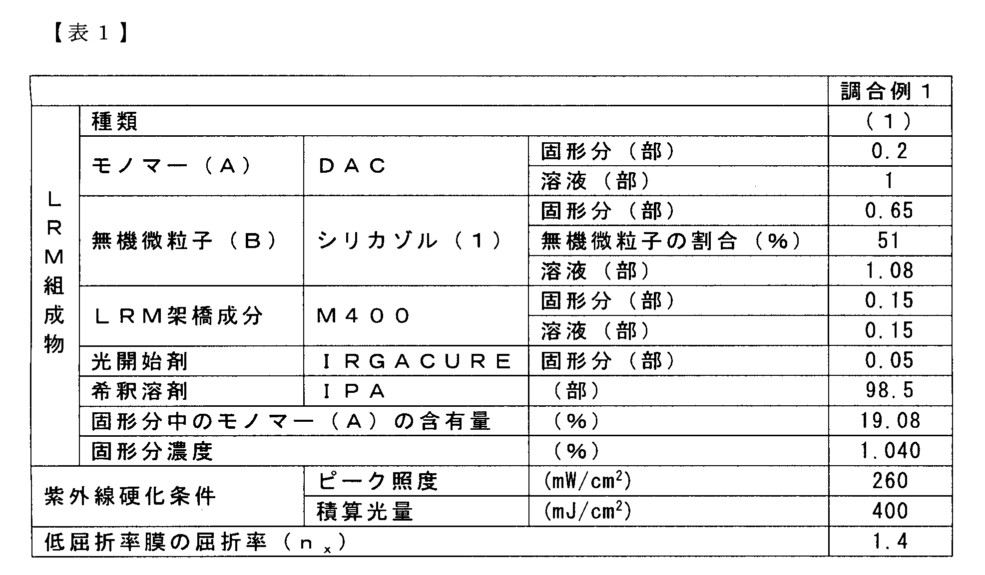
HRM組成物として、表2に示すHRM組成物(1)~(3)を調合した。
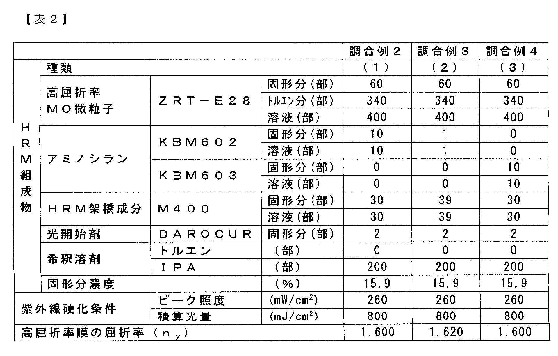
中屈折率組成物として、表3に示す中屈折率組成物(1)~(8)を調合した。
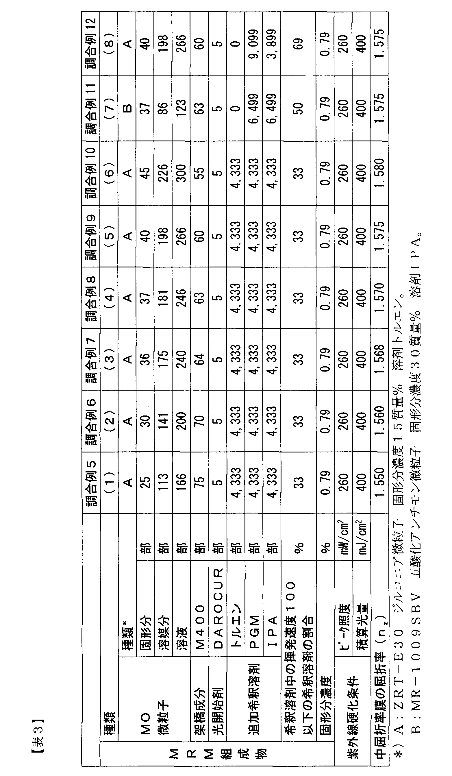
厚さ100μmのPETフィルム((株)東洋紡、商品名:A4100)のPET表面に、LRM組成物(1)を、10号バーコーターを用いて塗付し、100℃で1.5分間および150℃で1分間乾燥させてLRM組成物塗膜を形成した。なお、PET表面の臨界表面張力は44mN/mであった。
表4に示すようにMRM組成物を変更したこと以外は実施例1と同様に積層体を作製した。評価結果を表4に示す。
表4に示すようにMRM組成物を変更し、接着層形成材料としてU6HA 10部、C6DA 30部、M305 30部、M400 30部およびDAROCUR 2部を混合して得られる活性エネルギー線硬化性組成物に変更したこと以外は実施例1と同様に積層体を作製した。評価結果を表4に示す。
表5に示すようにHRM組成物およびMRM組成物を変更したこと以外は実施例1と同様に積層体を作製した。評価結果を表5に示す。
表5に示すようにHRM組成物およびMRM組成物を変更し、接着層形成材料としてU6HA 10部、C6DA 30部、M305 30部、M400 30部およびDAROCUR 2部を混合して得られる活性エネルギー線硬化性組成物に変更したこと以外は実施例1と同様に積層体を作製した。評価結果を表6に示す。
表6に示すようにHRM組成物を変更したこと以外は実施例2と同様に積層体を作製した。評価結果を表6に示す。
表6に示すように高屈折率膜の膜厚を変更したこと以外は実施例2と同様に積層体を作製した。評価結果を表6に示す。
表6に示すように中屈折率膜の膜厚を変更したこと以外は実施例2と同様に積層体を作製した。評価結果を表6に示す。
表7に示すようにMRM組成物を変更し、接着層形成材料としてU6HA 10部、C6DA 30部、M305 30部、M400 30部およびDAROCUR 2部を混合して得られる活性エネルギー線硬化性組成物に変更したこと以外は実施例1と同様に積層体を作製した。評価結果を表7に示す。
実施例2において、MRM組成物の製膜条件を下記に示すように変更したこと以外は実施例2と同様に積層体を作製した。評価結果を表7に示す。中屈折率膜中に膜中央領域が形成されていないため干渉模様が顕著であった。
MRM組成物(2)を、10号バーコーターを用いて塗付し、150℃で10分間乾燥させてMRM組成物の塗膜を形成し、9.6kWの高圧水銀ランプ(出力設定100%)の下20cmの位置のところを、4.5m/分の速度で通過させてMRM組成物の塗膜を硬化させて中屈折率膜が積層された積層フィルムを得た。このときの積算光量は400mJ/cm2で、ピーク照度は260mW/cm2であった。
実施例2において、中屈折率膜を形成しなかったこと以外は実施例2と同様に積層体を作製した。評価結果を表7に示す。中屈折率膜が存在しないため干渉模様が顕著に見えた。
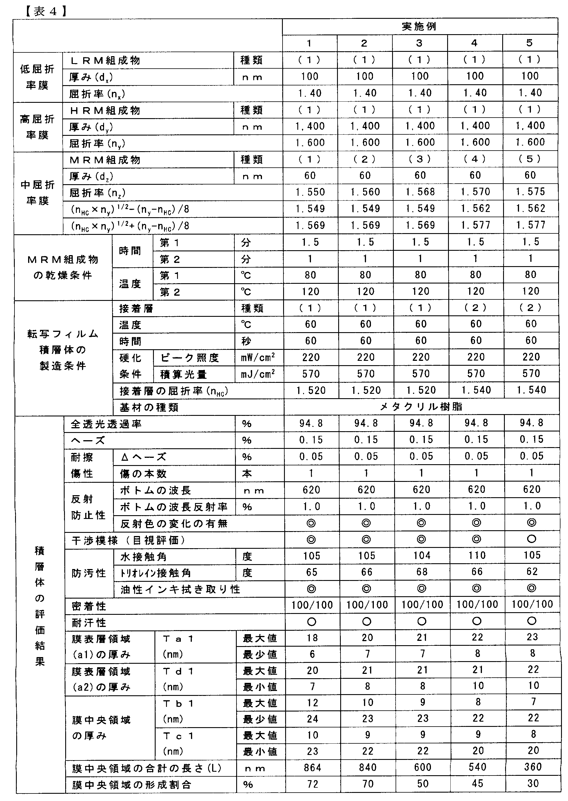
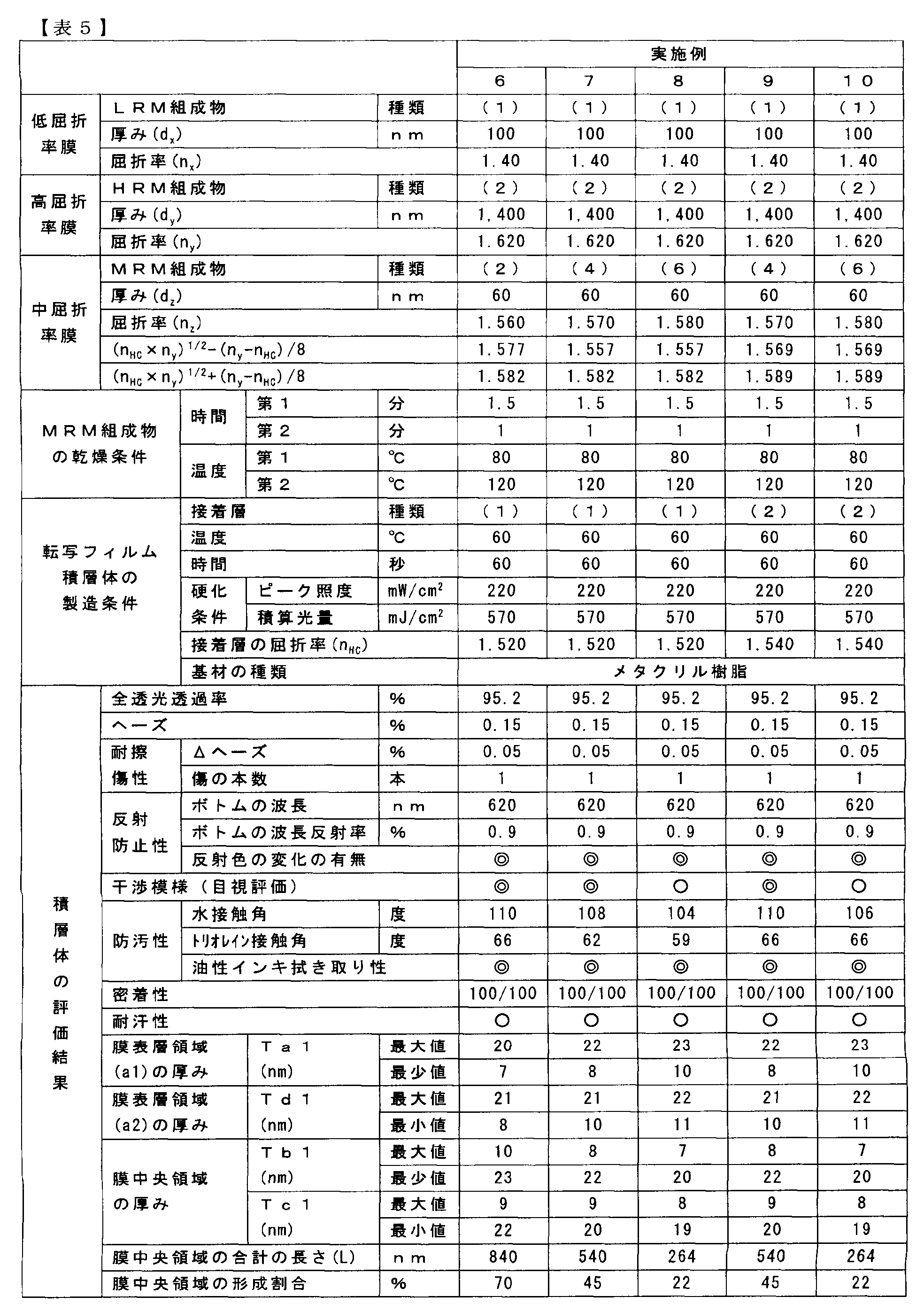

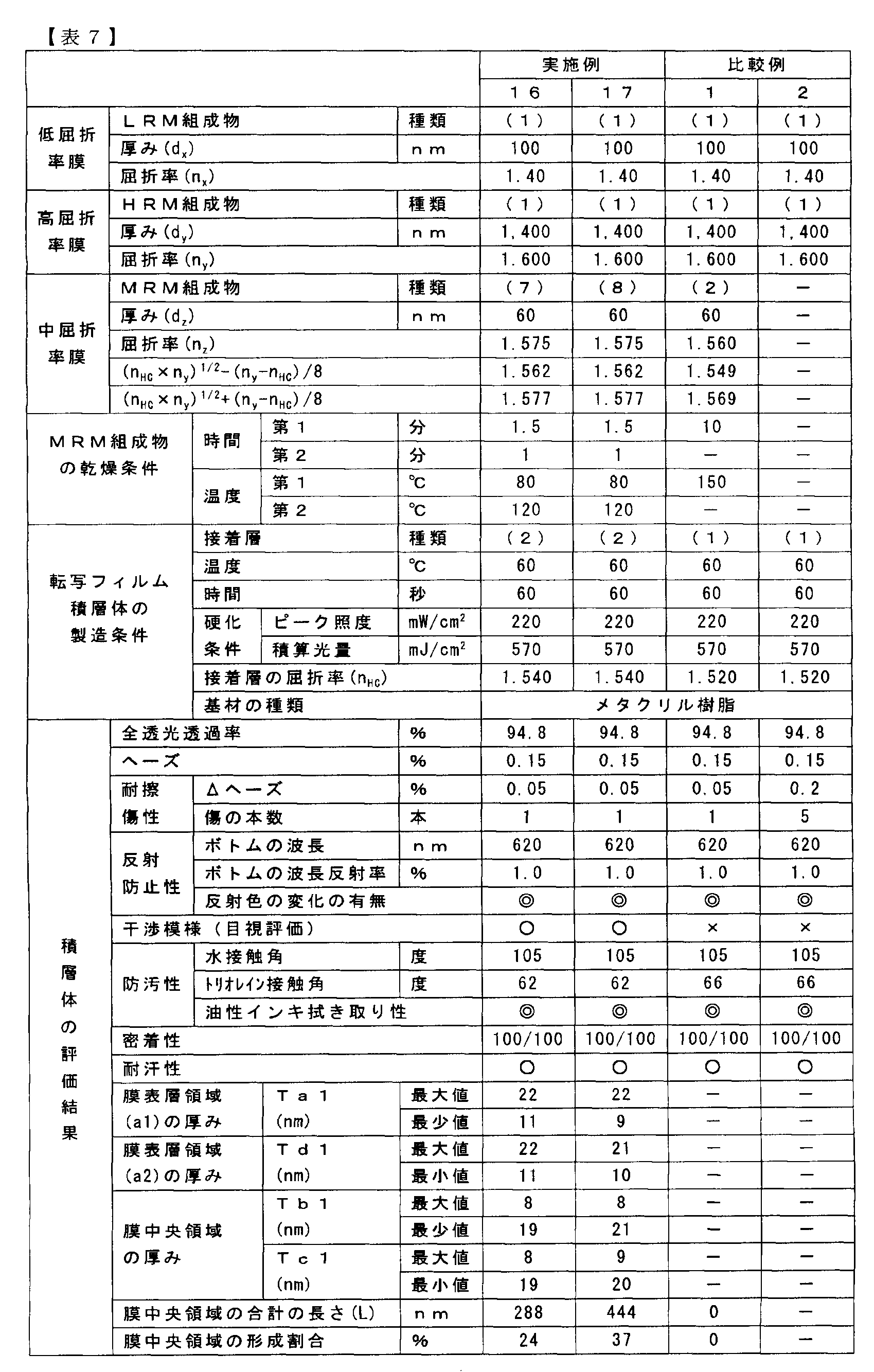
厚さ100μmのPETフィルム((株)東洋紡、商品名:A4100)のPET表面に、MRM組成物(1)を、10号バーコーターを用いて塗付し、80℃で1.5分間および120℃で1分間乾燥させてMRM組成物塗膜を形成し、9.6kWの高圧水銀ランプ(出力設定100%)の下20cmの位置のところを、4.5m/分の速度で通過させてMRM組成物の塗膜を硬化させて膜厚60nmの中屈折率膜が積層された積層フィルムを得た。このときの積算光量は400mJ/cm2で、ピーク照度は260mW/cm2であった。
Claims (14)
- 金属酸化物微粒子が存在しない膜中央領域と、膜中央領域の片側に金属酸化物微粒子が存在する膜表層領域(a1)が形成され、膜中央領域の他方側に金属酸化物微粒子が存在する膜表層領域(a2)が形成されている金属酸化物微粒子含有膜。
- 金属酸化物微粒子含有膜の厚み方向断面において、金属酸化物微粒子含有膜の中心から膜表層領域(a1)および膜表層領域(a2)と膜中央領域との界面までの膜中央領域の厚み(TbiおよびTci)並びに膜表層領域(a1)の厚み(Tai)および膜表層領域(a2)の厚み(Tdi)が下記式(1)~(4)を満足し、かつ、金属酸化物微粒子含有膜の厚み方向断面において、厚み方向断面内で金属酸化物微粒子含有膜の膜厚に対して、垂直方向の1200nmの長さにおける金属酸化物微粒子が存在しない膜中央領域の長さ(Li)の合計の長さ(L)が240nm以上である請求項1に記載の金属酸化物微粒子含有膜。
0.1T≦Tbi≦0.4T (1)
Tai=0.5T-Tbi (2)
0.1T≦Tci≦0.4T (3)
Tdi=0.5T-Tci (4)
但し、Tbi、Tci、Tai、TdiおよびLiはそれぞれi番目における膜中央領域または膜表層領域(a1)および膜表層領域(a2)の厚み並びに金属酸化物微粒子が存在しない膜中央領域の長さを示す。また、Tは金属酸化物微粒子含有膜の厚みを示す。 - 金属酸化物微粒子含有膜の屈折率が1.5~1.65である請求項1または2に記載の金属酸化物微粒子含有膜。
- 剥離用フィルムの片面に屈折率(Nx)を有する低屈折率膜、屈折率(Ny)を有する高屈折率膜および屈折率(Nz)を有する中屈折率膜がこの順に積層された転写フィルムであって、これらの屈折率は、波長594nmレーザーで測定され、かつ、下記式(5)を満足し、中屈折率膜が請求項1または2に記載の金属酸化物微粒子含有膜である転写フィルム。
Nx<Nz<Ny (5) - 低屈折率膜がパーフルオロポリエーテル基と窒素原子を含有するモノマー(A)単位を有するポリマーと無機微粒子を含有する請求項4に記載の転写フィルム。
- パーフルオロポリエーテル基と窒素原子を含有するモノマー(A)が下記構造式(1)で示されるモノマーである請求項5に記載の転写フィルム。

- 剥離用フィルムの片面に屈折率(Nx)を有する低屈折率膜、屈折率(Ny)を有する高屈折率膜および屈折率(Nz)を有する中屈折率膜として請求項1または2に記載の金属酸化物微粒子含有膜がこの順で積層され、これら屈折率は、波長594nmレーザーで測定され、かつ、下記式(5)を満足する転写フィルムの製造方法であって、剥離用フィルムの片面に低屈折率膜を積層した後に高屈折率膜を積層し、次いで高屈折率膜の表面に、金属酸化物微粒子および揮発速度が100以下の溶剤を20質量%以上含む希釈溶剤を含有する、金属酸化物微粒子含有膜用組成物を塗布した後に140℃以下の温度で希釈溶剤を乾燥させて、中屈折率膜を積層する転写フィルムの製造方法。
Nx<Nz<Ny (5) - 基材の少なくとも片面に、直接または他の層を介して、請求項1または2に記載の金属酸化物微粒子含有膜が積層された積層体(A)。
- 基材の少なくとも片面に、直接または他の層を介して、屈折率(Nz)を有する中屈折率膜、屈折率(Ny)を有する高屈折率膜および屈折率(Nx)を有する低屈折率膜がこの順に積層され、これら屈折率は、波長594nmレーザーで測定され、かつ、下記式(5)を満足する積層体(B)であって、中屈折率膜が請求項1または2に記載の金属酸化物微粒子含有膜である積層体(B)。
Nx<Nz<Ny (5) - 低屈折率膜がパーフルオロポリエーテル基と窒素原子を含有するモノマー(A)単位を有するポリマーと無機微粒子を含有する請求項9に記載の積層体。
- パーフルオロポリエーテル基と窒素原子を含有するモノマー(A)が下記構造式(1)で示されるモノマーである請求項10に記載の積層体。
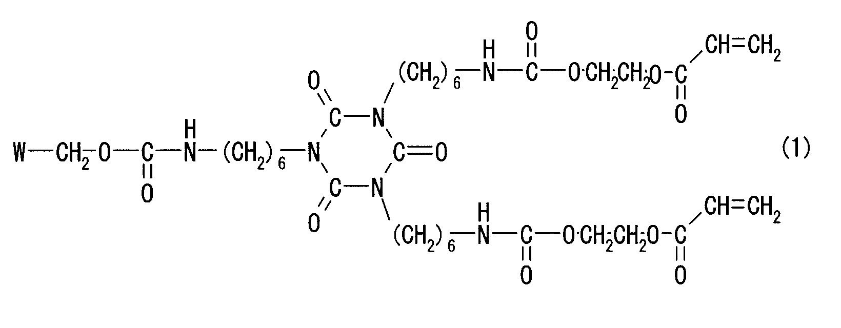
- 基材の表面に、金属酸化物微粒子および揮発速度が100以下の溶剤を20質量%以上含む溶剤を含有する金属酸化物微粒子含有膜を形成するための金属酸化物微粒子含有膜用組成物を塗布した後に140℃以下の温度で希釈溶剤を乾燥させることにより中屈折率膜を積層する請求項8に記載の積層体(A)の製造方法。
- 基材の少なくとも片面に、直接または他の層を介して、屈折率(Nz)を有する中屈折率膜、屈折率(Ny)を有する高屈折率膜および屈折率(Nx)を有する低屈折率膜がこの順に積層され、これら屈折率は、波長594nmレーザーで測定され、かつ、下記式(5)を満足する積層体(B)の製造方法であって、基材と請求項4~6のいずれか1項に記載の転写フィルムの中屈折率膜の面とを、接着層を形成するための塗膜を介して貼り合わせて転写フィルムラミネート物を形成する工程、接着層を形成するための塗膜から接着層を得て転写フィルム積層体を形成する工程、および転写フィルム積層体から剥離用フィルムを剥がして積層体を形成する工程を有する請求項9に記載の積層体(B)の製造方法。
Nx<Nz<Ny (5) - 接着層を形成するための塗膜が活性エネルギー線硬化性混合物を含み、転写フィルム積層体形成工程において、接着層を形成するための塗膜に活性エネルギー線を照射し、前記活性エネルギー線硬化性混合物を硬化させて接着層を得て転写フィルム積層体を形成する請求項13に記載の積層体の製造方法。
Priority Applications (5)
| Application Number | Priority Date | Filing Date | Title |
|---|---|---|---|
| JP2012501067A JP6079234B2 (ja) | 2010-12-22 | 2011-12-22 | 金属酸化物微粒子含有膜、転写フィルムおよびその製造方法並びに積層体およびその製造方法 |
| KR1020137019107A KR20130130031A (ko) | 2010-12-22 | 2011-12-22 | 금속 산화물 미립자 함유막, 전사 필름 및 그의 제조방법 및 적층체 및 그의 제조방법 |
| CN201180068284.2A CN103384839B (zh) | 2010-12-22 | 2011-12-22 | 含金属氧化物微粒膜、转印膜及其制造方法和层积体及其制造方法 |
| EP11851808.3A EP2657730A1 (en) | 2010-12-22 | 2011-12-22 | Film containing metal oxide particles, transfer film, method for producing same, laminate, and method for producing same |
| US13/996,992 US20130295331A1 (en) | 2010-12-22 | 2011-12-22 | Film containing metal oxide particles, transfer film and method for producing same, and laminate and method for producing same |
Applications Claiming Priority (2)
| Application Number | Priority Date | Filing Date | Title |
|---|---|---|---|
| JP2010285372 | 2010-12-22 | ||
| JP2010-285372 | 2010-12-22 |
Publications (1)
| Publication Number | Publication Date |
|---|---|
| WO2012086748A1 true WO2012086748A1 (ja) | 2012-06-28 |
Family
ID=46314015
Family Applications (1)
| Application Number | Title | Priority Date | Filing Date |
|---|---|---|---|
| PCT/JP2011/079796 Ceased WO2012086748A1 (ja) | 2010-12-22 | 2011-12-22 | 金属酸化物微粒子含有膜、転写フィルムおよびその製造方法並びに積層体およびその製造方法 |
Country Status (7)
| Country | Link |
|---|---|
| US (1) | US20130295331A1 (ja) |
| EP (1) | EP2657730A1 (ja) |
| JP (1) | JP6079234B2 (ja) |
| KR (1) | KR20130130031A (ja) |
| CN (1) | CN103384839B (ja) |
| TW (1) | TWI631879B (ja) |
| WO (1) | WO2012086748A1 (ja) |
Cited By (3)
| Publication number | Priority date | Publication date | Assignee | Title |
|---|---|---|---|---|
| JP2014011094A (ja) * | 2012-07-02 | 2014-01-20 | Mitsubishi Rayon Co Ltd | 有機el素子用基板および有機el素子 |
| WO2014115415A1 (ja) * | 2013-01-24 | 2014-07-31 | 富士フイルム株式会社 | 透明積層体およびその製造方法 |
| JP2023003762A (ja) * | 2021-06-24 | 2023-01-17 | 富士フイルム株式会社 | 転写フィルム、積層体、音響スピーカー、積層体の製造方法 |
Families Citing this family (3)
| Publication number | Priority date | Publication date | Assignee | Title |
|---|---|---|---|---|
| KR20120086308A (ko) * | 2009-10-09 | 2012-08-02 | 미츠비시 레이온 가부시키가이샤 | 전사 필름, 수지 적층체 및 그들의 제조 방법 |
| JP6429011B2 (ja) * | 2014-11-13 | 2018-11-28 | パナソニックIpマネジメント株式会社 | インモールド成型用転写フィルム及びその製造方法 |
| CN105070879A (zh) * | 2015-07-30 | 2015-11-18 | 河北中智电池制造有限公司 | 一种节能环保型锂电池极片制备工艺及设备 |
Citations (5)
| Publication number | Priority date | Publication date | Assignee | Title |
|---|---|---|---|---|
| JP2003103680A (ja) | 2001-09-28 | 2003-04-09 | Reiko Co Ltd | 反射防止用転写フイルム |
| JP2003322703A (ja) * | 2002-05-02 | 2003-11-14 | Fuji Photo Film Co Ltd | 反射防止フィルムおよびその形成方法、偏光板、画像表示装置 |
| JP2004310135A (ja) | 2004-07-23 | 2004-11-04 | Dainippon Printing Co Ltd | 光学機能性フィルムの製造方法 |
| JP2004345333A (ja) | 2002-06-24 | 2004-12-09 | Fuji Photo Film Co Ltd | プラスチックフイルム及び画像表示装置 |
| JP2007038199A (ja) * | 2004-11-15 | 2007-02-15 | Jsr Corp | 積層体の製造方法 |
Family Cites Families (19)
| Publication number | Priority date | Publication date | Assignee | Title |
|---|---|---|---|---|
| KR19980703086A (ko) * | 1996-01-18 | 1998-09-05 | 우메모토 타케시 | 다층 반사 방지 필름을 가진 플라스틱 광학 물품 |
| JP2004009420A (ja) * | 2002-06-05 | 2004-01-15 | Nakajima Kogyo Kk | 低反射転写箔、成型品の製造方法及び成型品 |
| JP3980423B2 (ja) * | 2002-07-01 | 2007-09-26 | 日東電工株式会社 | ハードコートフィルム、その製造方法、光学素子および画像表示装置 |
| JP2005096322A (ja) * | 2003-09-26 | 2005-04-14 | Dainippon Printing Co Ltd | 機能性層転写フィルム、並びに、防汚層及び機能性層転写体 |
| JP4525893B2 (ja) * | 2003-10-24 | 2010-08-18 | 信越化学工業株式会社 | 位相シフトマスクブランク、位相シフトマスク及びパターン転写方法 |
| JP4715746B2 (ja) * | 2004-03-18 | 2011-07-06 | Jsr株式会社 | 積層体の製造方法 |
| US7524553B2 (en) * | 2004-05-31 | 2009-04-28 | Fujifilm Corporation | Optical film, polarizing plate and image display using the same |
| JP2006037024A (ja) * | 2004-07-29 | 2006-02-09 | Daikin Ind Ltd | 反射防止膜形成用組成物 |
| JP5247977B2 (ja) * | 2005-01-31 | 2013-07-24 | Jsr株式会社 | 硬化性樹脂組成物及びそれからなる硬化膜 |
| JP5006528B2 (ja) * | 2005-07-13 | 2012-08-22 | 旭化成株式会社 | 帯電防止ハードコート用塗布組成物 |
| JP5148846B2 (ja) * | 2006-07-13 | 2013-02-20 | 日揮触媒化成株式会社 | 透明被膜形成用塗料および透明被膜付基材 |
| EP2180354B1 (en) * | 2007-08-21 | 2017-08-02 | Dexerials Corporation | Antireflection film |
| JP5380025B2 (ja) * | 2007-09-27 | 2014-01-08 | 富士フイルム株式会社 | 反射防止フィルム、偏光板、画像表示装置、および反射防止フィルム用透明支持体の製造方法 |
| EP2105767A1 (en) * | 2008-03-28 | 2009-09-30 | Fujifilm Corporation | Transparent support, optical film, polarizing plate and image display device |
| JP2010032795A (ja) * | 2008-07-29 | 2010-02-12 | Fujifilm Corp | ハードコートフィルム、ハードコートフィルムの製造方法、反射防止フィルム、偏光板および表示装置 |
| JP2010189294A (ja) * | 2009-02-17 | 2010-09-02 | Shin-Etsu Chemical Co Ltd | 光重合性官能基含有有機ケイ素化合物及びその製造方法 |
| JP2011039332A (ja) * | 2009-08-12 | 2011-02-24 | Fujifilm Corp | 光学フィルム、その製造方法、偏光板及び画像表示装置 |
| TWM386187U (en) * | 2009-10-28 | 2010-08-11 | Yang Zi De | Transfer printing membrane structure with the effect of light on color |
| JP5346969B2 (ja) * | 2011-03-04 | 2013-11-20 | 富士フイルム株式会社 | 防眩性フィルムの製造方法 |
-
2011
- 2011-12-22 CN CN201180068284.2A patent/CN103384839B/zh not_active Expired - Fee Related
- 2011-12-22 JP JP2012501067A patent/JP6079234B2/ja active Active
- 2011-12-22 EP EP11851808.3A patent/EP2657730A1/en not_active Withdrawn
- 2011-12-22 WO PCT/JP2011/079796 patent/WO2012086748A1/ja not_active Ceased
- 2011-12-22 TW TW100147975A patent/TWI631879B/zh active
- 2011-12-22 US US13/996,992 patent/US20130295331A1/en not_active Abandoned
- 2011-12-22 KR KR1020137019107A patent/KR20130130031A/ko not_active Withdrawn
Patent Citations (5)
| Publication number | Priority date | Publication date | Assignee | Title |
|---|---|---|---|---|
| JP2003103680A (ja) | 2001-09-28 | 2003-04-09 | Reiko Co Ltd | 反射防止用転写フイルム |
| JP2003322703A (ja) * | 2002-05-02 | 2003-11-14 | Fuji Photo Film Co Ltd | 反射防止フィルムおよびその形成方法、偏光板、画像表示装置 |
| JP2004345333A (ja) | 2002-06-24 | 2004-12-09 | Fuji Photo Film Co Ltd | プラスチックフイルム及び画像表示装置 |
| JP2004310135A (ja) | 2004-07-23 | 2004-11-04 | Dainippon Printing Co Ltd | 光学機能性フィルムの製造方法 |
| JP2007038199A (ja) * | 2004-11-15 | 2007-02-15 | Jsr Corp | 積層体の製造方法 |
Cited By (4)
| Publication number | Priority date | Publication date | Assignee | Title |
|---|---|---|---|---|
| JP2014011094A (ja) * | 2012-07-02 | 2014-01-20 | Mitsubishi Rayon Co Ltd | 有機el素子用基板および有機el素子 |
| WO2014115415A1 (ja) * | 2013-01-24 | 2014-07-31 | 富士フイルム株式会社 | 透明積層体およびその製造方法 |
| JP2014142834A (ja) * | 2013-01-24 | 2014-08-07 | Fujifilm Corp | 透明積層体およびその製造方法 |
| JP2023003762A (ja) * | 2021-06-24 | 2023-01-17 | 富士フイルム株式会社 | 転写フィルム、積層体、音響スピーカー、積層体の製造方法 |
Also Published As
| Publication number | Publication date |
|---|---|
| EP2657730A1 (en) | 2013-10-30 |
| JPWO2012086748A1 (ja) | 2014-06-05 |
| US20130295331A1 (en) | 2013-11-07 |
| TWI631879B (zh) | 2018-08-01 |
| TW201247040A (en) | 2012-11-16 |
| KR20130130031A (ko) | 2013-11-29 |
| CN103384839B (zh) | 2015-05-20 |
| JP6079234B2 (ja) | 2017-02-15 |
| CN103384839A (zh) | 2013-11-06 |
Similar Documents
| Publication | Publication Date | Title |
|---|---|---|
| JP6142531B2 (ja) | 転写フィルムおよびその製造方法並びに積層体およびその製造方法 | |
| JP5728945B2 (ja) | 防汚組成物、防汚膜、防汚積層膜、転写フィルム及び樹脂積層体、並びに樹脂積層体の製造方法 | |
| JP5810528B2 (ja) | 転写フィルム、樹脂積層体及びそれらの製造方法 | |
| JP5747439B2 (ja) | アクリル系樹脂シートを連続的に製造する方法 | |
| TWI404629B (zh) | 樹脂疊層體的製造方法 | |
| JP6079234B2 (ja) | 金属酸化物微粒子含有膜、転写フィルムおよびその製造方法並びに積層体およびその製造方法 | |
| JP2000187102A (ja) | 反射防止材料及びそれを用いた偏光フィルム | |
| JP6016009B2 (ja) | 転写フィルム、積層体及びそれらの製造方法 | |
| JP2006178276A (ja) | 反射防止積層フィルム | |
| JP6035871B2 (ja) | 反射防止積層体、その製造方法、及び画像表示装置 | |
| JP5601496B2 (ja) | 被膜用シリカゾルの製造方法、被膜用組成物、被膜、被膜を表層に有する樹脂積層体、及びその製造方法 | |
| JP2015090482A (ja) | 積層体及びその製造方法 | |
| JP2023053514A (ja) | 積層体、および、積層体の製造方法 | |
| JP2006337790A (ja) | 反射防止積層フィルム | |
| JP2006175782A (ja) | 反射防止積層フィルム |
Legal Events
| Date | Code | Title | Description |
|---|---|---|---|
| WWE | Wipo information: entry into national phase |
Ref document number: 2012501067 Country of ref document: JP |
|
| 121 | Ep: the epo has been informed by wipo that ep was designated in this application |
Ref document number: 11851808 Country of ref document: EP Kind code of ref document: A1 |
|
| WWE | Wipo information: entry into national phase |
Ref document number: 13996992 Country of ref document: US |
|
| NENP | Non-entry into the national phase |
Ref country code: DE |
|
| REEP | Request for entry into the european phase |
Ref document number: 2011851808 Country of ref document: EP |
|
| WWE | Wipo information: entry into national phase |
Ref document number: 2011851808 Country of ref document: EP |
|
| ENP | Entry into the national phase |
Ref document number: 20137019107 Country of ref document: KR Kind code of ref document: A |