WO2012090469A1 - 成形型 - Google Patents
成形型 Download PDFInfo
- Publication number
- WO2012090469A1 WO2012090469A1 PCT/JP2011/007256 JP2011007256W WO2012090469A1 WO 2012090469 A1 WO2012090469 A1 WO 2012090469A1 JP 2011007256 W JP2011007256 W JP 2011007256W WO 2012090469 A1 WO2012090469 A1 WO 2012090469A1
- Authority
- WO
- WIPO (PCT)
- Prior art keywords
- mold
- partial surface
- fiber
- laminate
- circumferential direction
- Prior art date
- Legal status (The legal status is an assumption and is not a legal conclusion. Google has not performed a legal analysis and makes no representation as to the accuracy of the status listed.)
- Ceased
Links
Images


Classifications
-
- B—PERFORMING OPERATIONS; TRANSPORTING
- B29—WORKING OF PLASTICS; WORKING OF SUBSTANCES IN A PLASTIC STATE IN GENERAL
- B29C—SHAPING OR JOINING OF PLASTICS; SHAPING OF MATERIAL IN A PLASTIC STATE, NOT OTHERWISE PROVIDED FOR; AFTER-TREATMENT OF THE SHAPED PRODUCTS, e.g. REPAIRING
- B29C41/00—Shaping by coating a mould, core or other substrate, i.e. by depositing material and stripping-off the shaped article; Apparatus therefor
- B29C41/34—Component parts, details or accessories; Auxiliary operations
- B29C41/38—Moulds, cores or other substrates
-
- B—PERFORMING OPERATIONS; TRANSPORTING
- B29—WORKING OF PLASTICS; WORKING OF SUBSTANCES IN A PLASTIC STATE IN GENERAL
- B29C—SHAPING OR JOINING OF PLASTICS; SHAPING OF MATERIAL IN A PLASTIC STATE, NOT OTHERWISE PROVIDED FOR; AFTER-TREATMENT OF THE SHAPED PRODUCTS, e.g. REPAIRING
- B29C33/00—Moulds or cores; Details thereof or accessories therefor
- B29C33/38—Moulds or cores; Details thereof or accessories therefor characterised by the material or the manufacturing process
- B29C33/3828—Moulds made of at least two different materials having different thermal conductivities
-
- B—PERFORMING OPERATIONS; TRANSPORTING
- B29—WORKING OF PLASTICS; WORKING OF SUBSTANCES IN A PLASTIC STATE IN GENERAL
- B29C—SHAPING OR JOINING OF PLASTICS; SHAPING OF MATERIAL IN A PLASTIC STATE, NOT OTHERWISE PROVIDED FOR; AFTER-TREATMENT OF THE SHAPED PRODUCTS, e.g. REPAIRING
- B29C33/00—Moulds or cores; Details thereof or accessories therefor
- B29C33/42—Moulds or cores; Details thereof or accessories therefor characterised by the shape of the moulding surface, e.g. ribs or grooves
-
- B—PERFORMING OPERATIONS; TRANSPORTING
- B29—WORKING OF PLASTICS; WORKING OF SUBSTANCES IN A PLASTIC STATE IN GENERAL
- B29C—SHAPING OR JOINING OF PLASTICS; SHAPING OF MATERIAL IN A PLASTIC STATE, NOT OTHERWISE PROVIDED FOR; AFTER-TREATMENT OF THE SHAPED PRODUCTS, e.g. REPAIRING
- B29C33/00—Moulds or cores; Details thereof or accessories therefor
- B29C33/38—Moulds or cores; Details thereof or accessories therefor characterised by the material or the manufacturing process
-
- B—PERFORMING OPERATIONS; TRANSPORTING
- B29—WORKING OF PLASTICS; WORKING OF SUBSTANCES IN A PLASTIC STATE IN GENERAL
- B29C—SHAPING OR JOINING OF PLASTICS; SHAPING OF MATERIAL IN A PLASTIC STATE, NOT OTHERWISE PROVIDED FOR; AFTER-TREATMENT OF THE SHAPED PRODUCTS, e.g. REPAIRING
- B29C70/00—Shaping composites, i.e. plastics material comprising reinforcements, fillers or preformed parts, e.g. inserts
- B29C70/04—Shaping composites, i.e. plastics material comprising reinforcements, fillers or preformed parts, e.g. inserts comprising reinforcements only, e.g. self-reinforcing plastics
- B29C70/28—Shaping operations therefor
- B29C70/40—Shaping or impregnating by compression not applied
- B29C70/42—Shaping or impregnating by compression not applied for producing articles of definite length, i.e. discrete articles
-
- B—PERFORMING OPERATIONS; TRANSPORTING
- B29—WORKING OF PLASTICS; WORKING OF SUBSTANCES IN A PLASTIC STATE IN GENERAL
- B29C—SHAPING OR JOINING OF PLASTICS; SHAPING OF MATERIAL IN A PLASTIC STATE, NOT OTHERWISE PROVIDED FOR; AFTER-TREATMENT OF THE SHAPED PRODUCTS, e.g. REPAIRING
- B29C33/00—Moulds or cores; Details thereof or accessories therefor
- B29C33/38—Moulds or cores; Details thereof or accessories therefor characterised by the material or the manufacturing process
- B29C33/40—Plastics, e.g. foam or rubber
-
- B—PERFORMING OPERATIONS; TRANSPORTING
- B29—WORKING OF PLASTICS; WORKING OF SUBSTANCES IN A PLASTIC STATE IN GENERAL
- B29C—SHAPING OR JOINING OF PLASTICS; SHAPING OF MATERIAL IN A PLASTIC STATE, NOT OTHERWISE PROVIDED FOR; AFTER-TREATMENT OF THE SHAPED PRODUCTS, e.g. REPAIRING
- B29C33/00—Moulds or cores; Details thereof or accessories therefor
- B29C33/44—Moulds or cores; Details thereof or accessories therefor with means for, or specially constructed to facilitate, the removal of articles, e.g. of undercut articles
- B29C33/48—Moulds or cores; Details thereof or accessories therefor with means for, or specially constructed to facilitate, the removal of articles, e.g. of undercut articles with means for collapsing or disassembling
-
- B—PERFORMING OPERATIONS; TRANSPORTING
- B29—WORKING OF PLASTICS; WORKING OF SUBSTANCES IN A PLASTIC STATE IN GENERAL
- B29L—INDEXING SCHEME ASSOCIATED WITH SUBCLASS B29C, RELATING TO PARTICULAR ARTICLES
- B29L2023/00—Tubular articles
-
- B—PERFORMING OPERATIONS; TRANSPORTING
- B29—WORKING OF PLASTICS; WORKING OF SUBSTANCES IN A PLASTIC STATE IN GENERAL
- B29L—INDEXING SCHEME ASSOCIATED WITH SUBCLASS B29C, RELATING TO PARTICULAR ARTICLES
- B29L2031/00—Other particular articles
- B29L2031/30—Vehicles, e.g. ships or aircraft, or body parts thereof
- B29L2031/3076—Aircrafts
- B29L2031/3082—Fuselages
-
- Y—GENERAL TAGGING OF NEW TECHNOLOGICAL DEVELOPMENTS; GENERAL TAGGING OF CROSS-SECTIONAL TECHNOLOGIES SPANNING OVER SEVERAL SECTIONS OF THE IPC; TECHNICAL SUBJECTS COVERED BY FORMER USPC CROSS-REFERENCE ART COLLECTIONS [XRACs] AND DIGESTS
- Y10—TECHNICAL SUBJECTS COVERED BY FORMER USPC
- Y10T—TECHNICAL SUBJECTS COVERED BY FORMER US CLASSIFICATION
- Y10T29/00—Metal working
- Y10T29/49—Method of mechanical manufacture
- Y10T29/49718—Repairing
-
- Y—GENERAL TAGGING OF NEW TECHNOLOGICAL DEVELOPMENTS; GENERAL TAGGING OF CROSS-SECTIONAL TECHNOLOGIES SPANNING OVER SEVERAL SECTIONS OF THE IPC; TECHNICAL SUBJECTS COVERED BY FORMER USPC CROSS-REFERENCE ART COLLECTIONS [XRACs] AND DIGESTS
- Y10—TECHNICAL SUBJECTS COVERED BY FORMER USPC
- Y10T—TECHNICAL SUBJECTS COVERED BY FORMER US CLASSIFICATION
- Y10T428/00—Stock material or miscellaneous articles
- Y10T428/249921—Web or sheet containing structurally defined element or component
Definitions
- the present invention relates to a mold used for manufacturing a composite material molded article.
- the outside of the fuselage of the aircraft is formed by a thin member called a skin panel (see, for example, Patent Document 1).
- a skin panel is integrally molded in a far wider range than before by using a fiber reinforced resin composite material (hereinafter simply referred to as “composite material”).
- composite material a fiber reinforced resin composite material
- the skin panel has a cylindrical shape near the center of the fuselage of a large aircraft, and the cylindrical skin panel is integrally formed without a seam.
- a prepreg is laminated on the outer surface of a cylindrical core (generally called “mandrel”), and the laminated prepreg (hereinafter referred to as “laminated body”).
- the whole is made cylindrical.
- the “prepreg” is a sheet-like material in which a woven fabric such as carbon fiber or a unidirectional material is impregnated with a semi-cured thermosetting resin (such as an epoxy resin).
- the laminate is cured by applying pressure and heat.
- the surface of the laminate is brought into close contact with a plate-like surface mold (generally called “curl plate”), and the smooth surface of the surface mold is transferred to the skin. Form the surface of the panel smoothly.
- curl plate plate-like surface mold
- a molding die is configured by combining a plurality of partial surface molds having the inner surface.
- the thermosetting resin causes a decrease in viscosity for a while due to the heat generated when the laminate is cured, so that the edge of the partial surface mold is pressed by pressure. This causes the problem of sinking into the laminate.
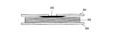
- a method using a joint member (generally called “pre-cure strip”) of a hardened composite material has been proposed. That is, as shown in FIG. 3A, the connecting member 203 is inserted between the partial surface mold 201 and the laminated body 202 corresponding to the joint between the partial surface molds 201, and is cured by applying pressure and heat. As a result, as shown in FIG. 3B, the connecting member 203 sinks into the laminate 202, and the portion corresponding to the joint of the partial surface mold 201 is formed smoothly. At this time, since the connecting member 203 is hardened in advance and is hard, the partial surface mold 201 does not sink into the connecting member 203.
- a surface type material it is preferable to use a composite material for reasons such as being easy to return to the original shape even if it is difficult to deform locally, but as a core type material it is easy to maintain and hardly deteriorates by heat, It is preferable to use a durable metal.
- a new problem arises. For example, referring to FIG. 3C, when the core mold 204 is formed of an Invar alloy with a small thermal expansion and the partial surface mold 201 is formed of a composite material, the thermal expansion coefficient of both is obtained when high temperature heat is applied. Due to the difference, the partial surface mold 201 expands more than the core mold 204.
- the partial surface mold 201 Due to the difference in thermal expansion between the partial surface mold 201 and the core mold 204, the partial surface mold 201 pulls the surface of the laminate 202 in the circumferential direction toward the connecting member 203, so that wrinkles 205 are formed on both sides of the connecting member 203. It will occur. If the depth of the wrinkles 205 is large, the strength of the skin panel may be reduced, which may cause damage.
- the present invention has been made to solve the above-described problems, and an object of the present invention is to provide a mold in which wrinkles are unlikely to occur when a laminated body in which prepregs are laminated is cured.
- the mold according to the present invention is a mold used for curing a cylindrical laminate in which prepregs are laminated, A core mold located on the inside of the laminate, and a surface mold consisting of a plurality of partial surface molds located on the outside of the laminate, wherein the partial surface molds are arranged in the circumferential direction of the laminate.
- the thermal expansion coefficient in the circumferential direction is close to the thermal expansion coefficient of the core mold. According to this configuration, since the thermal expansion coefficient in the circumferential direction of each partial surface mold is close to the thermal expansion coefficient in the circumferential direction of the core mold, it is possible to suppress the occurrence of wrinkles caused by the difference between the two thermal expansion coefficients.
- the core mold is formed of an invar alloy, and each partial surface mold has a greater amount of fibers having a fiber direction in the circumferential direction than an amount of fibers having a fiber direction in the axial direction. You may comprise so that it may become.
- the thermal expansion coefficient of the core mold is reduced by being formed of an invar alloy, but the partial surface mold has an amount of fibers whose circumferential direction is the fiber direction and an amount of fibers whose axial direction is the fiber direction. By controlling this ratio, the thermal expansion coefficient of the partial surface type in the circumferential direction can be brought close to the thermal expansion coefficient of the core mold.
- the partial surface mold can keep the thermal expansion coefficient in the circumferential direction low while having the strength necessary for operation. In addition, the coefficient of thermal expansion can be controlled.
- each of the partial surface molds includes a unidirectional material in which the fiber direction of the existing fiber is only in the circumferential direction and a woven material in which the fiber direction of the existing fiber is in the circumferential direction and the axial direction. You may form and laminate
- the laminate has a strength margin obtained by subtracting a thickness dimension required for strength from an actual thickness dimension depending on a circumferential position, and the partial surface molds are connected to each other.
- it may be arranged so as to be located at a circumferential position where the strength margin is larger than the periphery of the laminated body. According to such a configuration, since each partial surface mold is located at a portion where the strength margin of the laminate is large, even if a slight wrinkle occurs at a position corresponding to the boundary portion, the laminate is provided. The effect of lowering the strength can be kept small.
- the laminate has a strength margin obtained by subtracting a thickness dimension required for strength from an actual thickness dimension depending on a circumferential position, and the partial surface molds are connected to each other. May be arranged so as to be located at a circumferential position having the largest strength margin in the laminated body. According to such a configuration, even if wrinkles are generated in the laminated body, if the strength margin at that position is very large, it is possible to suppress the influence due to the strength reduction of the laminated body.
- the laminate is formed on a fuselage of an aircraft, and the surface mold is composed of 5 to 8 partial surface molds, You may arrange
- the coefficient of thermal expansion adjustment method according to the present invention is a method of adjusting the coefficient of thermal expansion of a member made of fiber reinforced resin, and increases or decreases the amount of fibers whose predetermined direction is the fiber direction. The coefficient of thermal expansion at is adjusted.
- the member which concerns on this invention is a member which uses the fiber reinforced resin as a material adjusted by said thermal expansion coefficient adjustment method.
- the coefficient of thermal expansion of each partial surface mold in the circumferential direction is close to the coefficient of thermal expansion of the core mold, so that wrinkles occur when the laminated body in which the prepreg is laminated is cured. Hateful.
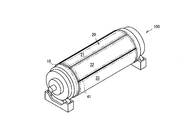
- FIG. 1 is a perspective view showing a use state of the mold 100 according to the present embodiment.
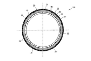
- FIG. 2 is a cross-sectional view of the state in which the surface mold 20 according to the present embodiment is attached to the laminate 30.
- the mold 100 according to the present embodiment includes a core mold 10 and a surface mold 20.
- each of these components will be described in order.
- the core mold 10 is a mold positioned inside a laminated body (skin panel that is a molded product after curing) 30 in which prepregs are laminated. As described above, the core mold 10 is generally called a “mandrel”. As shown in FIGS. 1 and 2, the core mold 10 according to the present embodiment has a cylindrical shape and is configured to be rotatable.
- the core mold 10 is formed of an invar alloy having excellent thermal durability and low thermal expansion characteristics.
- the “invar alloy” is a metal in which 34 to 36% of nickel is alloyed with iron and has a very low coefficient of thermal expansion.
- the thermal expansion coefficient (CTE) of Invar alloy is about 2.0 to 2.5 ⁇ 10 ⁇ 6 / ° C. As shown in FIG.
- a groove 11 extending in the axial direction is formed on the surface of the core mold 10, and a prepreg stringer 31 is inserted into this groove.
- the stringer 31 is a rod-like reinforcing member that receives an axial bending load in the fuselage of the aircraft, and constitutes a so-called one-piece barrel (OPB) together with the skin panel.
- the surface mold 20 is a mold located outside the laminated body (skin panel which is a molded product after curing) 30 in which prepregs are laminated. As described above, the surface mold 20 is generally called a “curl plate”. As shown in FIG. 2, the surface mold 20 according to the present embodiment is composed of seven partial surface molds 21 to 27, and the partial surface molds 21 to 27 are laminated in the circumferential direction of the laminate 30. The entire surface of the body 30 is covered. In other words, the surface mold 20 is divided into seven partial surface molds 21 to 27.
- the partial surface type a highly rigid one having a certain shape (the inner peripheral surface has an arc shape) is used, but in the present embodiment, it is elastically deformed from a flat plate shape to a curved shape. Use what you can. Details of the partial surface molds 21 to 27 will be described later.
- the stringer 31 is embedded in the groove 11 on the surface of the core mold 10, and the prepreg is stacked on the surface of the core mold 10 while rotating the core mold 10 in this state, thereby forming the entire laminate 30 in a cylindrical shape.
- the number of prepregs to be stacked varies depending on the position at which the prepregs are stacked. For example, if there are portions where the number of prepregs to be stacked is about 12, some 100 prepregs are stacked because of the necessity of reinforcement in openings (for example, portions corresponding to door mounting portions) where the strength is significantly reduced.
- the partial surface molds 21 to 27 are attached to the surface of the laminate 30 in the circumferential direction.
- a connecting member 40 pre-cured strip
- the laminated body 30 is sealed by sticking a belt-like bag film 41 to the joints of the partial surface molds 21 to 27, and then evacuated.
- the core mold 10 and the entire surface mold 20 are further covered with a bag film (not shown) and evacuated.
- the core mold 10, the laminate 30, and the surface mold 20 (partial surface molds 21 to 27) fixed integrally with the bag film are placed in an autoclave (high-temperature high-pressure kettle), and high-temperature heat and high pressure are simultaneously applied.
- the laminate is cured.
- the laminate 30 is deformed while being pressed by the surface mold 20, the unevenness and undulations existing on the surface of the laminate 30 are eliminated, and the surface of the laminate 30 is smoothly molded.
- a stringer is adhere
- the above is the outline of the mold 100 according to the embodiment of the present invention.
- the seven partial surface molds 21 to 27 constituting the surface mold 20 have a thickness of about 1.5 mm and have flexibility.
- the partial surface molds 21 to 27 are formed of a carbon fiber reinforced resin (hereinafter referred to as “CFRP”) in which the amount of fibers whose circumferential direction is the fiber direction is larger than the amount of fibers whose axial direction is the fiber direction.
- CFRP carbon fiber reinforced resin
- the carbon fiber of CFRP plays a role of suppressing deformation in the fiber direction. This is true not only in the case of deformation due to external force but also in the case of deformation due to application of heat. That is, the carbon fiber can suppress the thermal expansion coefficient in the fiber direction, and the partial surface molds 21 to 27 according to the present embodiment have a thermal expansion coefficient in the circumferential direction smaller than the thermal expansion coefficient in the axial direction. Is formed.
- a method for manufacturing the partial surface molds 21 to 27 will be described.
- a fiber cloth material reinforced resin prepreg hereinafter referred to as “woven material” means this prepreg
- a fiber unidirectional material reinforced resin prepreg hereinafter referred to as “unidirectional material” having only the circumferential direction as the fiber direction.
- this prepreg is combined) and a total of about 10 sheets are laminated.
- the fibers of each prepreg are carbon fibers
- the resin is an epoxy resin or a bismaleimide resin.
- the laminated prepreg is wrapped in a vacuum bag and evacuated, and in that state, heat and pressure are applied to cure. Thereafter, the cured prepreg (molded product) is taken out of the vacuum bag and cut into predetermined dimensions.
- the number of prepregs laminated here is merely an example, and is not limited to this.
- the amount of fibers having the fiber direction as the axial direction in the woven material is 1, the amount of fibers having the fiber direction as the circumferential direction in the woven material is 1, and the circumferential direction in the unidirectional material is the fiber direction.
- the amount of fibers to be 2 is 2, and the amount of fibers having the axial direction in the unidirectional material as the fiber direction is zero.
- the amount of fibers whose axial direction is the fiber direction as a whole 1, and the amount of fibers whose circumferential direction is the fiber direction is 3 as a whole. become.
- the thermal expansion coefficient in the circumferential direction is 2.5 ⁇ 10 ⁇ 6 / ° C.
- the thermal expansion coefficient in the circumferential direction of the partial surface type (conventional example) formed only from the conventional fabric material is 5.0 ⁇ .
- the value is close to 2.0 to 2.5 ⁇ 10 ⁇ 6 / ° C., which is the thermal expansion coefficient in the circumferential direction of the core mold 10.
- the partial surface type (reference example) in which the amount of fibers whose axial direction is the fiber direction is 1 and the amount of fibers whose circumferential direction is the fiber direction is 7 is 1.5 ⁇ in the circumferential direction. Although it is as low as 10 ⁇ 6 / ° C., the strength in the axial direction is relatively low, so that it is easily broken and there are some problems in terms of operation. As described above, if the amount of the fiber whose circumferential direction is the fiber direction is increased with respect to the amount of the fiber whose axial direction is the fiber direction, the thermal expansion coefficient in the circumferential direction is reduced, but the fiber whose circumferential direction is the fiber direction.
- the CFRP used for the partial surface molds 21 to 27 desirably has an amount of fibers having the axial direction as the fiber direction and an amount of fibers having the circumferential direction as the fiber direction of 2 to 5.
- the table below summarizes the above contents.
- “0” simply indicates a unidirectional material with the circumferential direction as the fiber direction, and is described as “(0.90)”. Indicates a textile material.
- “s” indicates that the other half is stacked in the order in which it is applied and in the order of the object. For example, in the case of the reference example, after one woven material is first laminated, three unidirectional materials are continuously laminated. The remaining half represents that three sheets of unidirectional material are continuously stacked and then one woven material is finally stacked.
- the “fiber amount ratio” represents the ratio of the amount of fibers whose circumferential direction is the fiber direction and the amount of fibers whose axial direction is the fiber direction.
- the thermal expansion coefficient in the circumferential direction of the partial surface molds 21 to 27 can be made closer to the thermal expansion coefficient in the circumferential direction of the core mold 10. Therefore, when the laminate 30 is cured, the difference (positional deviation) in the amount of thermal expansion between the core mold 10 and the partial surface molds 21 to 27 in the circumferential direction can be suppressed. Thereby, it can suppress that a wrinkle generate
- fiber reinforced resin a technique of increasing the amount of fibers in a predetermined direction in order to increase the “strength” in a predetermined direction has been conventionally known.
- the partial surface molds 21 to 27 of the present embodiment have a larger allowable range of thermal expansion in the axial direction than in the circumferential direction. That is, the wrinkle problem described above occurs in the vicinity of the joint between the partial surface molds 21 to 27. However, since this joint does not exist in the axial direction, the wrinkle problem cannot occur, and the thermal expansion in the axial direction does not occur. It is acceptable to some extent.
- the laminated body 30 when the laminated body 30 is laminated on the core mold 10, it is not possible to completely adhere to the core mold 10, and it is easy to cause wrinkles to be laminated in a slightly swollen state, but if the partial surface mold is used, Since the amount of swelling does not drag, it can be dispersed.
- the thickness dimension is not uniform over the entire circumference but varies depending on the circumferential position.
- the thickness dimension at each circumferential position is determined in consideration of the strength required at that position. For example, the thickness dimension is about 2 mm in a portion where the required strength is relatively low, while the door mounting portion and the like where high strength is required has a thickness size of about 20 mm. Since the molded product is a part of the aircraft, the thickness is not increased more than necessary to reduce the weight.
- the difference between the thickness dimension required for strength and the actual thickness dimension is larger than other parts.
- a thickness dimension of 20 mm in strength is necessary at a certain position, and a thickness dimension of 10 mm in strength is necessary in a position adjacent to this.
- the boundary between both positions is not formed in a staircase shape, but is smoothly formed in a slope shape.
- the part formed in this slope shape is a part where the actual thickness dimension is relatively larger than the thickness dimension required for strength.
- a value obtained by subtracting a thickness dimension required for strength from an actual thickness dimension is defined as “strength margin”, and the joints between the partial surface molds 21 to 27 are the strength of the laminate 30. It is arranged so that it is located in the part where the margin is large.
- the optimal arrangement of the partial surface molds 21 to 27 varies depending on the molded product, and the dimensions and arrangement of the partial surface molds 21 to 27 shown in the present embodiment are merely examples.
- the arrangement of the partial surface molds 21 to 27 according to the present embodiment will be described with reference to FIG. 2 from the viewpoint of the reference circumferential direction position, the number of components, and the circumferential dimension.
- the partial surface molds 21 to 27 shown in FIG. 2 are sequentially rotated from the top in the clockwise direction, the first partial surface mold 21, the second partial surface mold 22, the third partial surface mold 23, and the fourth partial surface mold 24.
- the fifth partial surface mold 25, the sixth partial surface mold 26, and the seventh partial surface mold 27 will be referred to.
- the top part of the laminated body 30 in FIG. 2 shall correspond to the top part of a body fuselage.
- the term “top portion of the laminate” means a portion corresponding to the top portion of the skin panel that is a molded product (the top portion of the fuselage body).
- the reference circumferential position is a circumferential position that serves as a reference when the partial surface molds 21 to 27 are arranged.
- the top part of the laminated body 30 is set as the reference circumferential direction position.
- mold 21 is arrange
- the surface mold 25 is relatively arranged.
- the reason why the top portion of the laminate 30 is set to the reference circumferential direction position is that the skin panel, which is a molded product, has a substantially right / left target shape, and the strength margin is also symmetrically distributed.
- the first partial surface mold 21 is arranged so as to cover the reference circumferential direction position.
- the joint between the first partial surface mold 21 and the second partial surface mold 22 is the reference circumferential direction position. You may arrange
- the top portion of the laminated body 30 is not set as the reference circumferential direction position, and the portion having the highest strength margin of the laminated body 30 is set as the reference circumferential direction position.
- the joint between the first partial surface mold 21 and the second partial surface mold 22 is These may be arranged so as to be located at the above-mentioned reference circumferential direction positions.
- the number of components is the number of partial surface molds 21 to 27 constituting the surface mold 20. In the present embodiment, the number of components is seven. Regardless of the number of components, the amount of thermal expansion in the circumferential direction of the surface die 20 as a whole is constant. If the number of partial surface dies 21 to 27 increases and the number of joints increases, the amount of thermal expansion per joint becomes small. Therefore, if the number of components is large, wrinkles are less likely to occur in the laminate 30. However, if the number of components increases too much, the burden of the work of attaching the partial surface molds 21 to 27 to the laminate 30 increases, and the circumferential dimension of the partial surface molds 21 to 27 becomes too small. In some cases, it may become impossible to attach to the body 30. In consideration of the above points, when the diameter of the laminated body 30 is about 6 m, it is desirable that the surface mold 20 is composed of 5 to 8 partial surface molds.
- the circumferential dimension is the circumferential dimension of each partial surface mold 21-27.
- the circumferential dimension is not uniform.
- the second partial surface mold 22 and the seventh partial surface mold 27, the third partial surface mold 23 and the sixth partial surface mold 26, and the fourth partial surface mold 24 and the fifth partial surface mold 25 have the same circumference. Although it is a direction dimension, it has the circumferential direction dimension which is mutually different except these.
- the circumferential dimensions of the partial surface molds 21 to 27 are not uniform, but the joints between the partial surface molds 21 to 27 can be positioned more accurately in the portion having the high strength margin. Partial surface molds 21 to 27 are arranged.
- the circumferential dimensions of the partial surface molds 21 to 27 are the same (within a predetermined range).
- the circumferential dimension of each of the partial surface molds 21 to 27 is 2.5 to 3.0 m.
- the mold 100 according to the present embodiment since the thermal expansion coefficient in the circumferential direction of each of the partial molds 21 to 27 is close to the thermal expansion coefficient in the circumferential direction of the core mold 10, wrinkles are hardly generated in the molded product. Furthermore, even if wrinkles are generated, the strength margin is large in the portion where the wrinkles are generated, so that it is possible to suppress the influence of the strength reduction of the laminate.
Landscapes
- Engineering & Computer Science (AREA)
- Mechanical Engineering (AREA)
- Manufacturing & Machinery (AREA)
- Chemical & Material Sciences (AREA)
- Composite Materials (AREA)
- Moulds For Moulding Plastics Or The Like (AREA)
- Moulding By Coating Moulds (AREA)
Abstract
Description
まず、図1及び図2を参照しながら、本実施形態に係る成形型100の概要について説明する。なお、本実施形態に係る成形型100は、大型航空機の胴体部のスキンパネルを成形するものである。また、このスキンパネルは、直径が約6mで軸方向長さが約7mの円筒形状を有するものとする。図1は、本実施形態に係る成形型100の使用状態を示した斜視図である。また、図2は、本実施形態に係る表面型20を積層体30に取り付けた状態の断面図である。図1に示すように、本実施形態に係る成形型100は、芯型10と、表面型20とを備えている。以下、これらの各構成要素について順に説明する。
次に、本実施形態に係る部分成形型21~27についてさらに詳細に説明する。表面型20を構成する7枚の部分表面型21~27は、厚みが1.5mm程度であり、可撓性を有している。また、部分表面型21~27は、周方向を繊維方向とする繊維の量が軸方向を繊維方向とする繊維の量よりも多い炭素繊維強化樹脂(以下、「CFRP」と称す。)により形成されている。CFRPの炭素繊維は繊維方向への変形を抑制する役割を果たしている。これは、外力を受けたことによる変形の場合だけでなく、熱を加えられたことによる変形の場合にも当てはまる。つまり、炭素繊維はその繊維方向における熱膨張率を抑えることができ、本実施形態に係る部分表面型21~27は、周方向における熱膨張率が軸方向における熱膨張率よりも小さくなるように形成されている。

次に、本実施形態に係る部分成形型21~27の配置について説明する。ここでは初めに、積層体30を硬化して得られる本実施形態に係る成形品(スキンパネル)について説明する。本実施形態に係る成形品は、厚み寸法が全周において均一ではなく周方向位置によって異なる。各周方向位置における厚み寸法は、その位置において必要となる強度を考慮して決定される。例えば、要求される強度が比較的低い部分では厚み寸法が2mm程度であるのに対し、高い強度が要求されるドアの取付部分などは厚み寸法が20mm程度である。成形品は航空機の一部であることから、重量を抑えるために必要以上に厚み寸法が大きくならないように形成される。ただし、そのような成形品であっても、強度上必要とされる厚み寸法と実際の厚み寸法との差が他の部分に比べて大きい部分は存在する。例えば、ある位置において強度上20mmの厚み寸法が必要であり、これに隣接する位置では強度上10mmの厚み寸法が必要であるとする。この場合、両位置の境界は階段状に形成されるのではなく、スロープ状に滑らかに形成される。そうすると、このスロープ状に形成された部分は、強度上必要とされる厚み寸法に比べ実際の厚み寸法が比較的大きい部分であるといえる。
20 表面型
21~27 部分表面型
30 積層体
40 繋ぎ部材
100 成形型
Claims (9)
- プリプレグを積層した円筒形状の積層体を硬化させる際に使用する成形型であって、
前記積層体の内側に位置する芯型と、
前記積層体の外側に位置し、複数の部分表面型からなる表面型と、を備え、
前記各部分表面型は、前記積層体の周方向に並んで外周面全体を覆うとともに、周方向を繊維方向とする繊維の量と軸方向を繊維方向とする繊維の量が異なる繊維強化樹脂によって形成されており、
前記各部分表面型は、軸方向に比べて周方向における熱膨張率が前記芯型の熱膨張率に近くなるように構成されている、成形型。 - 前記芯型はインバー合金によって形成されており、前記各部分表面型は周方向を繊維方向とする繊維の量が軸方向を繊維方向とする繊維の量よりも多い、請求項1に記載の成形型。
- 前記軸方向を繊維方向とする繊維の量が1に対し前記周方向を繊維方向とする繊維の量が2~5である、請求項2に記載の成形型。
- 前記各部分表面型は、内在する繊維の繊維方向が周方向のみの一方向材と、内在する繊維の繊維方向が周方向及び軸方向の織物材とを所定の割合で積層して形成されている、請求項3に記載の成形型。
- 前記積層体は、実際の厚み寸法から強度上必要とされる厚み寸法を引いた強度マージンが周方向位置によって異なっており、
前記各部分表面型は、互いのつなぎ目が、前記積層体のうちの周辺よりも前記強度マージンが大きい周方向位置に位置するように配置されている、請求項1に記載の成形型。 - 前記積層体は、実際の厚み寸法から強度上必要とされる厚み寸法を引いた強度マージンが周方向位置によって異なっており、
前記各部分表面型は、互いのつなぎ目の1つが、前記積層体のうちの最も前記強度マージンの大きい周方向位置に位置するように配置されている、請求項1に記載の成形型。 - 前記積層体は航空機の胴体部に形成されるものであって、
前記表面型は、5~8枚の部分表面型によって構成されており、
前記部分表面型は、前記胴体部の頂部に位置する部分を中心に左右対象に配置されている、請求項5又は6に記載の成形型。 - 繊維強化樹脂を材料とする部材の熱膨張率調整方法であって、所定の方向を繊維方向とする繊維の量を増減させて当該所定の方向における熱膨張率を調整する、熱膨張率調整方法。
- 請求項8に記載の熱膨張率調整方法によって調整された、繊維強化樹脂を材料とする部材。
Priority Applications (4)
| Application Number | Priority Date | Filing Date | Title |
|---|---|---|---|
| KR1020137014841A KR101498406B1 (ko) | 2010-12-27 | 2011-12-26 | 성형형 |
| US13/976,871 US9969106B2 (en) | 2010-12-27 | 2011-12-26 | Mold |
| EP11852909.8A EP2660028B1 (en) | 2010-12-27 | 2011-12-26 | Mold |
| US15/870,598 US10118316B2 (en) | 2010-12-27 | 2018-01-12 | Mold |
Applications Claiming Priority (2)
| Application Number | Priority Date | Filing Date | Title |
|---|---|---|---|
| JP2010-290402 | 2010-12-27 | ||
| JP2010290402A JP5698526B2 (ja) | 2010-12-27 | 2010-12-27 | 成形型 |
Related Child Applications (2)
| Application Number | Title | Priority Date | Filing Date |
|---|---|---|---|
| US13/976,871 A-371-Of-International US9969106B2 (en) | 2010-12-27 | 2011-12-26 | Mold |
| US15/870,598 Division US10118316B2 (en) | 2010-12-27 | 2018-01-12 | Mold |
Publications (1)
| Publication Number | Publication Date |
|---|---|
| WO2012090469A1 true WO2012090469A1 (ja) | 2012-07-05 |
Family
ID=46382606
Family Applications (1)
| Application Number | Title | Priority Date | Filing Date |
|---|---|---|---|
| PCT/JP2011/007256 Ceased WO2012090469A1 (ja) | 2010-12-27 | 2011-12-26 | 成形型 |
Country Status (5)
| Country | Link |
|---|---|
| US (2) | US9969106B2 (ja) |
| EP (1) | EP2660028B1 (ja) |
| JP (1) | JP5698526B2 (ja) |
| KR (1) | KR101498406B1 (ja) |
| WO (1) | WO2012090469A1 (ja) |
Cited By (1)
| Publication number | Priority date | Publication date | Assignee | Title |
|---|---|---|---|---|
| JP2014233924A (ja) * | 2013-06-04 | 2014-12-15 | 三菱航空機株式会社 | 繊維強化プラスチック部材の成形方法および成形装置 |
Families Citing this family (6)
| Publication number | Priority date | Publication date | Assignee | Title |
|---|---|---|---|---|
| US20170036375A1 (en) | 2015-08-07 | 2017-02-09 | Hexcel Corporation | Multi-sectional composite tooling |
| US11331867B2 (en) * | 2016-08-23 | 2022-05-17 | Textron Innovations, Inc. | Nested manufacturing of composite structures |
| JP6902753B2 (ja) * | 2017-06-05 | 2021-07-14 | 株式会社岩間工業所 | 炭素繊維強化樹脂部材の製造方法 |
| CN113752596A (zh) * | 2021-09-08 | 2021-12-07 | 北京蓝科盈晟航空科技有限公司 | 一种复合材料缠绕芯模法兰的定位结构及其安装拆卸方法 |
| US20250001707A1 (en) * | 2021-11-29 | 2025-01-02 | Toray Industries, Inc. | Manufacturing device and molding method for rotary-component reinforcement carbon fiber reinforced plastic |
| CN115609956B (zh) * | 2022-10-17 | 2024-04-30 | 中国人民解放军国防科技大学 | 一种异形筒成型模具及成型方法 |
Citations (6)
| Publication number | Priority date | Publication date | Assignee | Title |
|---|---|---|---|---|
| JPH05131555A (ja) * | 1991-11-11 | 1993-05-28 | Yokohama Rubber Co Ltd:The | 繊維補強熱可塑性樹脂中空体の成形型 |
| JPH10278185A (ja) * | 1997-04-10 | 1998-10-20 | Mitsubishi Electric Corp | サンドイッチ構造体の製造方法 |
| JP2002212310A (ja) * | 2000-11-14 | 2002-07-31 | Polymatech Co Ltd | 高分子複合材料成形体及びその製造方法 |
| JP2004276478A (ja) * | 2003-03-17 | 2004-10-07 | Polymatech Co Ltd | 高分子複合材料成形体およびその製造方法 |
| JP2009035001A (ja) * | 2007-08-02 | 2009-02-19 | Boeing Co:The | 複合材部品の表面に出現する不整合を最小化するための方法および装置 |
| JP2009526697A (ja) | 2006-02-17 | 2009-07-23 | エアバス ドイッチュラント ゲゼルシャフト ミット ベシュレンクテル ハフツング | 航空機用構成要素の非オートクレーブ接着方法 |
Family Cites Families (4)
| Publication number | Priority date | Publication date | Assignee | Title |
|---|---|---|---|---|
| JPH07299829A (ja) * | 1994-04-28 | 1995-11-14 | Nitto Boseki Co Ltd | 繊維補強熱可塑性樹脂中空体の成形方法及び成形型 |
| GB0712535D0 (en) * | 2007-06-28 | 2007-08-08 | Airbus Uk Ltd | Method for forming composite components and tool for use therein |
| GB0810870D0 (en) * | 2008-06-13 | 2008-07-23 | Advanced Composite Components | Tooling |
| DE102009020190B3 (de) * | 2009-05-07 | 2010-09-09 | Eads Deutschland Gmbh | Vorrichtung zur Formgebung eines Werkstücks |
-
2010
- 2010-12-27 JP JP2010290402A patent/JP5698526B2/ja active Active
-
2011
- 2011-12-26 KR KR1020137014841A patent/KR101498406B1/ko active Active
- 2011-12-26 EP EP11852909.8A patent/EP2660028B1/en active Active
- 2011-12-26 WO PCT/JP2011/007256 patent/WO2012090469A1/ja not_active Ceased
- 2011-12-26 US US13/976,871 patent/US9969106B2/en active Active
-
2018
- 2018-01-12 US US15/870,598 patent/US10118316B2/en active Active
Patent Citations (6)
| Publication number | Priority date | Publication date | Assignee | Title |
|---|---|---|---|---|
| JPH05131555A (ja) * | 1991-11-11 | 1993-05-28 | Yokohama Rubber Co Ltd:The | 繊維補強熱可塑性樹脂中空体の成形型 |
| JPH10278185A (ja) * | 1997-04-10 | 1998-10-20 | Mitsubishi Electric Corp | サンドイッチ構造体の製造方法 |
| JP2002212310A (ja) * | 2000-11-14 | 2002-07-31 | Polymatech Co Ltd | 高分子複合材料成形体及びその製造方法 |
| JP2004276478A (ja) * | 2003-03-17 | 2004-10-07 | Polymatech Co Ltd | 高分子複合材料成形体およびその製造方法 |
| JP2009526697A (ja) | 2006-02-17 | 2009-07-23 | エアバス ドイッチュラント ゲゼルシャフト ミット ベシュレンクテル ハフツング | 航空機用構成要素の非オートクレーブ接着方法 |
| JP2009035001A (ja) * | 2007-08-02 | 2009-02-19 | Boeing Co:The | 複合材部品の表面に出現する不整合を最小化するための方法および装置 |
Cited By (1)
| Publication number | Priority date | Publication date | Assignee | Title |
|---|---|---|---|---|
| JP2014233924A (ja) * | 2013-06-04 | 2014-12-15 | 三菱航空機株式会社 | 繊維強化プラスチック部材の成形方法および成形装置 |
Also Published As
| Publication number | Publication date |
|---|---|
| KR101498406B1 (ko) | 2015-03-03 |
| US20130344315A1 (en) | 2013-12-26 |
| EP2660028B1 (en) | 2017-06-14 |
| US10118316B2 (en) | 2018-11-06 |
| EP2660028A4 (en) | 2015-12-02 |
| KR20130105873A (ko) | 2013-09-26 |
| EP2660028A1 (en) | 2013-11-06 |
| JP2012135967A (ja) | 2012-07-19 |
| US20180133933A1 (en) | 2018-05-17 |
| JP5698526B2 (ja) | 2015-04-08 |
| US9969106B2 (en) | 2018-05-15 |
Similar Documents
| Publication | Publication Date | Title |
|---|---|---|
| JP5698526B2 (ja) | 成形型 | |
| JP5931906B2 (ja) | フランジを備えた複合構造体を成形する方法 | |
| CN102325646B (zh) | 通过嵌入预固化纤维增强树脂层制造风轮机叶片的方法 | |
| KR102197337B1 (ko) | 안정화 부재를 구비한 복합 구조물 | |
| US8703269B2 (en) | Reinforced composite structures for aircrafts and methods for making the same | |
| EP2660031B1 (en) | Molding jig and molding method | |
| JP6325545B2 (ja) | フランジ付き構成要素を製造するための装置およびその製造方法 | |
| JP5315713B2 (ja) | Frp製部材用プリフォームの製造方法 | |
| JP6785866B2 (ja) | 複合材の成形方法及び複合材の成形用治具 | |
| EP2890546B1 (en) | Method for bonding a stiffener to a surface and apparatus | |
| US10744724B2 (en) | Composite aircraft manufacturing tooling and methods using articulating mandrels | |
| US11198267B2 (en) | Bulk factor compensated tool for fabrication of a composite part | |
| EP3838569B1 (en) | Method for forming fibre composite preforms | |
| JP2007015351A (ja) | 積層複合材の矯正治具、矯正方法、および成形品 | |
| JP2007118598A (ja) | プリフォームの製造方法および製造装置 | |
| EP2295228B1 (en) | Method of manufacturing a fuselage frame of composite material | |
| CN104385625B (zh) | 基于卸载孔的复合材料薄壁壳体制备方法 | |
| CN104385626A (zh) | 基于间断铺层的复合材料薄壁壳体的制备方法 | |
| JP2023115678A (ja) | 複合材の成形方法及び複合材の成形治具 | |
| JP6000201B2 (ja) | 繊維強化プラスチック筒状部材の製造方法 |
Legal Events
| Date | Code | Title | Description |
|---|---|---|---|
| 121 | Ep: the epo has been informed by wipo that ep was designated in this application |
Ref document number: 11852909 Country of ref document: EP Kind code of ref document: A1 |
|
| ENP | Entry into the national phase |
Ref document number: 20137014841 Country of ref document: KR Kind code of ref document: A |
|
| NENP | Non-entry into the national phase |
Ref country code: DE |
|
| REEP | Request for entry into the european phase |
Ref document number: 2011852909 Country of ref document: EP |
|
| WWE | Wipo information: entry into national phase |
Ref document number: 2011852909 Country of ref document: EP |
|
| WWE | Wipo information: entry into national phase |
Ref document number: 13976871 Country of ref document: US |