WO2012091077A1 - 電池の劣化度の検出方法 - Google Patents
電池の劣化度の検出方法 Download PDFInfo
- Publication number
- WO2012091077A1 WO2012091077A1 PCT/JP2011/080350 JP2011080350W WO2012091077A1 WO 2012091077 A1 WO2012091077 A1 WO 2012091077A1 JP 2011080350 W JP2011080350 W JP 2011080350W WO 2012091077 A1 WO2012091077 A1 WO 2012091077A1
- Authority
- WO
- WIPO (PCT)
- Prior art keywords
- battery
- deterioration
- degree
- current
- soh
- Prior art date
- Legal status (The legal status is an assumption and is not a legal conclusion. Google has not performed a legal analysis and makes no representation as to the accuracy of the status listed.)
- Ceased
Links
Images



Classifications
-
- B—PERFORMING OPERATIONS; TRANSPORTING
- B60—VEHICLES IN GENERAL
- B60L—PROPULSION OF ELECTRICALLY-PROPELLED VEHICLES; SUPPLYING ELECTRIC POWER FOR AUXILIARY EQUIPMENT OF ELECTRICALLY-PROPELLED VEHICLES; ELECTRODYNAMIC BRAKE SYSTEMS FOR VEHICLES IN GENERAL; MAGNETIC SUSPENSION OR LEVITATION FOR VEHICLES; MONITORING OPERATING VARIABLES OF ELECTRICALLY-PROPELLED VEHICLES; ELECTRIC SAFETY DEVICES FOR ELECTRICALLY-PROPELLED VEHICLES
- B60L3/00—Electric devices on electrically-propelled vehicles for safety purposes; Monitoring operating variables, e.g. speed, deceleration or energy consumption
- B60L3/0023—Detecting, eliminating, remedying or compensating for drive train abnormalities, e.g. failures within the drive train
- B60L3/0046—Detecting, eliminating, remedying or compensating for drive train abnormalities, e.g. failures within the drive train relating to electric energy storage systems, e.g. batteries or capacitors
-
- B—PERFORMING OPERATIONS; TRANSPORTING
- B60—VEHICLES IN GENERAL
- B60L—PROPULSION OF ELECTRICALLY-PROPELLED VEHICLES; SUPPLYING ELECTRIC POWER FOR AUXILIARY EQUIPMENT OF ELECTRICALLY-PROPELLED VEHICLES; ELECTRODYNAMIC BRAKE SYSTEMS FOR VEHICLES IN GENERAL; MAGNETIC SUSPENSION OR LEVITATION FOR VEHICLES; MONITORING OPERATING VARIABLES OF ELECTRICALLY-PROPELLED VEHICLES; ELECTRIC SAFETY DEVICES FOR ELECTRICALLY-PROPELLED VEHICLES
- B60L50/00—Electric propulsion with power supplied within the vehicle
- B60L50/50—Electric propulsion with power supplied within the vehicle using propulsion power supplied by batteries or fuel cells
- B60L50/51—Electric propulsion with power supplied within the vehicle using propulsion power supplied by batteries or fuel cells characterised by AC-motors
-
- B—PERFORMING OPERATIONS; TRANSPORTING
- B60—VEHICLES IN GENERAL
- B60L—PROPULSION OF ELECTRICALLY-PROPELLED VEHICLES; SUPPLYING ELECTRIC POWER FOR AUXILIARY EQUIPMENT OF ELECTRICALLY-PROPELLED VEHICLES; ELECTRODYNAMIC BRAKE SYSTEMS FOR VEHICLES IN GENERAL; MAGNETIC SUSPENSION OR LEVITATION FOR VEHICLES; MONITORING OPERATING VARIABLES OF ELECTRICALLY-PROPELLED VEHICLES; ELECTRIC SAFETY DEVICES FOR ELECTRICALLY-PROPELLED VEHICLES
- B60L58/00—Methods or circuit arrangements for monitoring or controlling batteries or fuel cells, specially adapted for electric vehicles
- B60L58/10—Methods or circuit arrangements for monitoring or controlling batteries or fuel cells, specially adapted for electric vehicles for monitoring or controlling batteries
- B60L58/12—Methods or circuit arrangements for monitoring or controlling batteries or fuel cells, specially adapted for electric vehicles for monitoring or controlling batteries responding to state of charge [SoC]
- B60L58/13—Maintaining the SoC within a determined range
-
- B—PERFORMING OPERATIONS; TRANSPORTING
- B60—VEHICLES IN GENERAL
- B60L—PROPULSION OF ELECTRICALLY-PROPELLED VEHICLES; SUPPLYING ELECTRIC POWER FOR AUXILIARY EQUIPMENT OF ELECTRICALLY-PROPELLED VEHICLES; ELECTRODYNAMIC BRAKE SYSTEMS FOR VEHICLES IN GENERAL; MAGNETIC SUSPENSION OR LEVITATION FOR VEHICLES; MONITORING OPERATING VARIABLES OF ELECTRICALLY-PROPELLED VEHICLES; ELECTRIC SAFETY DEVICES FOR ELECTRICALLY-PROPELLED VEHICLES
- B60L58/00—Methods or circuit arrangements for monitoring or controlling batteries or fuel cells, specially adapted for electric vehicles
- B60L58/10—Methods or circuit arrangements for monitoring or controlling batteries or fuel cells, specially adapted for electric vehicles for monitoring or controlling batteries
- B60L58/12—Methods or circuit arrangements for monitoring or controlling batteries or fuel cells, specially adapted for electric vehicles for monitoring or controlling batteries responding to state of charge [SoC]
- B60L58/15—Preventing overcharging
-
- B—PERFORMING OPERATIONS; TRANSPORTING
- B60—VEHICLES IN GENERAL
- B60L—PROPULSION OF ELECTRICALLY-PROPELLED VEHICLES; SUPPLYING ELECTRIC POWER FOR AUXILIARY EQUIPMENT OF ELECTRICALLY-PROPELLED VEHICLES; ELECTRODYNAMIC BRAKE SYSTEMS FOR VEHICLES IN GENERAL; MAGNETIC SUSPENSION OR LEVITATION FOR VEHICLES; MONITORING OPERATING VARIABLES OF ELECTRICALLY-PROPELLED VEHICLES; ELECTRIC SAFETY DEVICES FOR ELECTRICALLY-PROPELLED VEHICLES
- B60L58/00—Methods or circuit arrangements for monitoring or controlling batteries or fuel cells, specially adapted for electric vehicles
- B60L58/10—Methods or circuit arrangements for monitoring or controlling batteries or fuel cells, specially adapted for electric vehicles for monitoring or controlling batteries
- B60L58/16—Methods or circuit arrangements for monitoring or controlling batteries or fuel cells, specially adapted for electric vehicles for monitoring or controlling batteries responding to battery ageing, e.g. to the number of charging cycles or the state of health [SoH]
-
- B—PERFORMING OPERATIONS; TRANSPORTING
- B60—VEHICLES IN GENERAL
- B60L—PROPULSION OF ELECTRICALLY-PROPELLED VEHICLES; SUPPLYING ELECTRIC POWER FOR AUXILIARY EQUIPMENT OF ELECTRICALLY-PROPELLED VEHICLES; ELECTRODYNAMIC BRAKE SYSTEMS FOR VEHICLES IN GENERAL; MAGNETIC SUSPENSION OR LEVITATION FOR VEHICLES; MONITORING OPERATING VARIABLES OF ELECTRICALLY-PROPELLED VEHICLES; ELECTRIC SAFETY DEVICES FOR ELECTRICALLY-PROPELLED VEHICLES
- B60L8/00—Electric propulsion with power supply from forces of nature, e.g. sun or wind
- B60L8/003—Converting light into electric energy, e.g. by using photo-voltaic systems
-
- G—PHYSICS
- G01—MEASURING; TESTING
- G01R—MEASURING ELECTRIC VARIABLES; MEASURING MAGNETIC VARIABLES
- G01R31/00—Arrangements for testing electric properties; Arrangements for locating electric faults; Arrangements for electrical testing characterised by what is being tested not provided for elsewhere
- G01R31/36—Arrangements for testing, measuring or monitoring the electrical condition of accumulators or electric batteries, e.g. capacity or state of charge [SoC]
- G01R31/382—Arrangements for monitoring battery or accumulator variables, e.g. SoC
-
- G—PHYSICS
- G01—MEASURING; TESTING
- G01R—MEASURING ELECTRIC VARIABLES; MEASURING MAGNETIC VARIABLES
- G01R31/00—Arrangements for testing electric properties; Arrangements for locating electric faults; Arrangements for electrical testing characterised by what is being tested not provided for elsewhere
- G01R31/36—Arrangements for testing, measuring or monitoring the electrical condition of accumulators or electric batteries, e.g. capacity or state of charge [SoC]
- G01R31/392—Determining battery ageing or deterioration, e.g. state of health
-
- H—ELECTRICITY
- H01—ELECTRIC ELEMENTS
- H01M—PROCESSES OR MEANS, e.g. BATTERIES, FOR THE DIRECT CONVERSION OF CHEMICAL ENERGY INTO ELECTRICAL ENERGY
- H01M10/00—Secondary cells; Manufacture thereof
- H01M10/42—Methods or arrangements for servicing or maintenance of secondary cells or secondary half-cells
- H01M10/48—Accumulators combined with arrangements for measuring, testing or indicating the condition of cells, e.g. the level or density of the electrolyte
-
- H—ELECTRICITY
- H02—GENERATION; CONVERSION OR DISTRIBUTION OF ELECTRIC POWER
- H02J—ELECTRIC POWER NETWORKS; CIRCUIT ARRANGEMENTS OR SYSTEMS FOR SUPPLYING OR DISTRIBUTING ELECTRIC POWER; SYSTEMS FOR STORING ELECTRIC ENERGY
- H02J7/00—Circuit arrangements for charging or discharging batteries or for supplying loads from batteries
- H02J7/80—Circuit arrangements for charging or discharging batteries or for supplying loads from batteries including monitoring or indicating arrangements
- H02J7/82—Control of state of charge [SOC]
-
- H—ELECTRICITY
- H02—GENERATION; CONVERSION OR DISTRIBUTION OF ELECTRIC POWER
- H02J—ELECTRIC POWER NETWORKS; CIRCUIT ARRANGEMENTS OR SYSTEMS FOR SUPPLYING OR DISTRIBUTING ELECTRIC POWER; SYSTEMS FOR STORING ELECTRIC ENERGY
- H02J7/00—Circuit arrangements for charging or discharging batteries or for supplying loads from batteries
- H02J7/80—Circuit arrangements for charging or discharging batteries or for supplying loads from batteries including monitoring or indicating arrangements
- H02J7/84—Control of state of health [SOH]
-
- B—PERFORMING OPERATIONS; TRANSPORTING
- B60—VEHICLES IN GENERAL
- B60L—PROPULSION OF ELECTRICALLY-PROPELLED VEHICLES; SUPPLYING ELECTRIC POWER FOR AUXILIARY EQUIPMENT OF ELECTRICALLY-PROPELLED VEHICLES; ELECTRODYNAMIC BRAKE SYSTEMS FOR VEHICLES IN GENERAL; MAGNETIC SUSPENSION OR LEVITATION FOR VEHICLES; MONITORING OPERATING VARIABLES OF ELECTRICALLY-PROPELLED VEHICLES; ELECTRIC SAFETY DEVICES FOR ELECTRICALLY-PROPELLED VEHICLES
- B60L2210/00—Converter types
- B60L2210/10—DC to DC converters
-
- B—PERFORMING OPERATIONS; TRANSPORTING
- B60—VEHICLES IN GENERAL
- B60L—PROPULSION OF ELECTRICALLY-PROPELLED VEHICLES; SUPPLYING ELECTRIC POWER FOR AUXILIARY EQUIPMENT OF ELECTRICALLY-PROPELLED VEHICLES; ELECTRODYNAMIC BRAKE SYSTEMS FOR VEHICLES IN GENERAL; MAGNETIC SUSPENSION OR LEVITATION FOR VEHICLES; MONITORING OPERATING VARIABLES OF ELECTRICALLY-PROPELLED VEHICLES; ELECTRIC SAFETY DEVICES FOR ELECTRICALLY-PROPELLED VEHICLES
- B60L2240/00—Control parameters of input or output; Target parameters
- B60L2240/40—Drive Train control parameters
- B60L2240/54—Drive Train control parameters related to batteries
- B60L2240/545—Temperature
-
- B—PERFORMING OPERATIONS; TRANSPORTING
- B60—VEHICLES IN GENERAL
- B60L—PROPULSION OF ELECTRICALLY-PROPELLED VEHICLES; SUPPLYING ELECTRIC POWER FOR AUXILIARY EQUIPMENT OF ELECTRICALLY-PROPELLED VEHICLES; ELECTRODYNAMIC BRAKE SYSTEMS FOR VEHICLES IN GENERAL; MAGNETIC SUSPENSION OR LEVITATION FOR VEHICLES; MONITORING OPERATING VARIABLES OF ELECTRICALLY-PROPELLED VEHICLES; ELECTRIC SAFETY DEVICES FOR ELECTRICALLY-PROPELLED VEHICLES
- B60L2240/00—Control parameters of input or output; Target parameters
- B60L2240/40—Drive Train control parameters
- B60L2240/54—Drive Train control parameters related to batteries
- B60L2240/547—Voltage
-
- B—PERFORMING OPERATIONS; TRANSPORTING
- B60—VEHICLES IN GENERAL
- B60L—PROPULSION OF ELECTRICALLY-PROPELLED VEHICLES; SUPPLYING ELECTRIC POWER FOR AUXILIARY EQUIPMENT OF ELECTRICALLY-PROPELLED VEHICLES; ELECTRODYNAMIC BRAKE SYSTEMS FOR VEHICLES IN GENERAL; MAGNETIC SUSPENSION OR LEVITATION FOR VEHICLES; MONITORING OPERATING VARIABLES OF ELECTRICALLY-PROPELLED VEHICLES; ELECTRIC SAFETY DEVICES FOR ELECTRICALLY-PROPELLED VEHICLES
- B60L2240/00—Control parameters of input or output; Target parameters
- B60L2240/40—Drive Train control parameters
- B60L2240/54—Drive Train control parameters related to batteries
- B60L2240/549—Current
-
- G—PHYSICS
- G01—MEASURING; TESTING
- G01R—MEASURING ELECTRIC VARIABLES; MEASURING MAGNETIC VARIABLES
- G01R31/00—Arrangements for testing electric properties; Arrangements for locating electric faults; Arrangements for electrical testing characterised by what is being tested not provided for elsewhere
- G01R31/36—Arrangements for testing, measuring or monitoring the electrical condition of accumulators or electric batteries, e.g. capacity or state of charge [SoC]
- G01R31/382—Arrangements for monitoring battery or accumulator variables, e.g. SoC
- G01R31/3842—Arrangements for monitoring battery or accumulator variables, e.g. SoC combining voltage and current measurements
-
- G—PHYSICS
- G01—MEASURING; TESTING
- G01R—MEASURING ELECTRIC VARIABLES; MEASURING MAGNETIC VARIABLES
- G01R31/00—Arrangements for testing electric properties; Arrangements for locating electric faults; Arrangements for electrical testing characterised by what is being tested not provided for elsewhere
- G01R31/36—Arrangements for testing, measuring or monitoring the electrical condition of accumulators or electric batteries, e.g. capacity or state of charge [SoC]
- G01R31/389—Measuring internal impedance, internal conductance or related variables
-
- H—ELECTRICITY
- H01—ELECTRIC ELEMENTS
- H01M—PROCESSES OR MEANS, e.g. BATTERIES, FOR THE DIRECT CONVERSION OF CHEMICAL ENERGY INTO ELECTRICAL ENERGY
- H01M10/00—Secondary cells; Manufacture thereof
- H01M10/42—Methods or arrangements for servicing or maintenance of secondary cells or secondary half-cells
- H01M10/46—Accumulators structurally combined with charging apparatus
- H01M10/465—Accumulators structurally combined with charging apparatus with solar battery as charging system
-
- H—ELECTRICITY
- H01—ELECTRIC ELEMENTS
- H01M—PROCESSES OR MEANS, e.g. BATTERIES, FOR THE DIRECT CONVERSION OF CHEMICAL ENERGY INTO ELECTRICAL ENERGY
- H01M10/00—Secondary cells; Manufacture thereof
- H01M10/42—Methods or arrangements for servicing or maintenance of secondary cells or secondary half-cells
- H01M10/48—Accumulators combined with arrangements for measuring, testing or indicating the condition of cells, e.g. the level or density of the electrolyte
- H01M10/486—Accumulators combined with arrangements for measuring, testing or indicating the condition of cells, e.g. the level or density of the electrolyte for measuring temperature
-
- H—ELECTRICITY
- H01—ELECTRIC ELEMENTS
- H01M—PROCESSES OR MEANS, e.g. BATTERIES, FOR THE DIRECT CONVERSION OF CHEMICAL ENERGY INTO ELECTRICAL ENERGY
- H01M2220/00—Batteries for particular applications
- H01M2220/20—Batteries in motive systems, e.g. vehicle, ship, plane
-
- H—ELECTRICITY
- H02—GENERATION; CONVERSION OR DISTRIBUTION OF ELECTRIC POWER
- H02J—ELECTRIC POWER NETWORKS; CIRCUIT ARRANGEMENTS OR SYSTEMS FOR SUPPLYING OR DISTRIBUTING ELECTRIC POWER; SYSTEMS FOR STORING ELECTRIC ENERGY
- H02J7/00—Circuit arrangements for charging or discharging batteries or for supplying loads from batteries
- H02J7/34—Parallel operation in networks using both storage and other DC sources, e.g. providing buffering
- H02J7/35—Parallel operation in networks using both storage and other DC sources, e.g. providing buffering with light sensitive cells
-
- Y—GENERAL TAGGING OF NEW TECHNOLOGICAL DEVELOPMENTS; GENERAL TAGGING OF CROSS-SECTIONAL TECHNOLOGIES SPANNING OVER SEVERAL SECTIONS OF THE IPC; TECHNICAL SUBJECTS COVERED BY FORMER USPC CROSS-REFERENCE ART COLLECTIONS [XRACs] AND DIGESTS
- Y02—TECHNOLOGIES OR APPLICATIONS FOR MITIGATION OR ADAPTATION AGAINST CLIMATE CHANGE
- Y02E—REDUCTION OF GREENHOUSE GAS [GHG] EMISSIONS, RELATED TO ENERGY GENERATION, TRANSMISSION OR DISTRIBUTION
- Y02E60/00—Enabling technologies; Technologies with a potential or indirect contribution to GHG emissions mitigation
- Y02E60/10—Energy storage using batteries
-
- Y—GENERAL TAGGING OF NEW TECHNOLOGICAL DEVELOPMENTS; GENERAL TAGGING OF CROSS-SECTIONAL TECHNOLOGIES SPANNING OVER SEVERAL SECTIONS OF THE IPC; TECHNICAL SUBJECTS COVERED BY FORMER USPC CROSS-REFERENCE ART COLLECTIONS [XRACs] AND DIGESTS
- Y02—TECHNOLOGIES OR APPLICATIONS FOR MITIGATION OR ADAPTATION AGAINST CLIMATE CHANGE
- Y02T—CLIMATE CHANGE MITIGATION TECHNOLOGIES RELATED TO TRANSPORTATION
- Y02T10/00—Road transport of goods or passengers
- Y02T10/60—Other road transportation technologies with climate change mitigation effect
- Y02T10/70—Energy storage systems for electromobility, e.g. batteries
-
- Y—GENERAL TAGGING OF NEW TECHNOLOGICAL DEVELOPMENTS; GENERAL TAGGING OF CROSS-SECTIONAL TECHNOLOGIES SPANNING OVER SEVERAL SECTIONS OF THE IPC; TECHNICAL SUBJECTS COVERED BY FORMER USPC CROSS-REFERENCE ART COLLECTIONS [XRACs] AND DIGESTS
- Y02—TECHNOLOGIES OR APPLICATIONS FOR MITIGATION OR ADAPTATION AGAINST CLIMATE CHANGE
- Y02T—CLIMATE CHANGE MITIGATION TECHNOLOGIES RELATED TO TRANSPORTATION
- Y02T10/00—Road transport of goods or passengers
- Y02T10/60—Other road transportation technologies with climate change mitigation effect
- Y02T10/7072—Electromobility specific charging systems or methods for batteries, ultracapacitors, supercapacitors or double-layer capacitors
-
- Y—GENERAL TAGGING OF NEW TECHNOLOGICAL DEVELOPMENTS; GENERAL TAGGING OF CROSS-SECTIONAL TECHNOLOGIES SPANNING OVER SEVERAL SECTIONS OF THE IPC; TECHNICAL SUBJECTS COVERED BY FORMER USPC CROSS-REFERENCE ART COLLECTIONS [XRACs] AND DIGESTS
- Y02—TECHNOLOGIES OR APPLICATIONS FOR MITIGATION OR ADAPTATION AGAINST CLIMATE CHANGE
- Y02T—CLIMATE CHANGE MITIGATION TECHNOLOGIES RELATED TO TRANSPORTATION
- Y02T10/00—Road transport of goods or passengers
- Y02T10/60—Other road transportation technologies with climate change mitigation effect
- Y02T10/72—Electric energy management in electromobility
-
- Y—GENERAL TAGGING OF NEW TECHNOLOGICAL DEVELOPMENTS; GENERAL TAGGING OF CROSS-SECTIONAL TECHNOLOGIES SPANNING OVER SEVERAL SECTIONS OF THE IPC; TECHNICAL SUBJECTS COVERED BY FORMER USPC CROSS-REFERENCE ART COLLECTIONS [XRACs] AND DIGESTS
- Y02—TECHNOLOGIES OR APPLICATIONS FOR MITIGATION OR ADAPTATION AGAINST CLIMATE CHANGE
- Y02T—CLIMATE CHANGE MITIGATION TECHNOLOGIES RELATED TO TRANSPORTATION
- Y02T90/00—Enabling technologies or technologies with a potential or indirect contribution to GHG emissions mitigation
- Y02T90/10—Technologies relating to charging of electric vehicles
- Y02T90/12—Electric charging stations
-
- Y—GENERAL TAGGING OF NEW TECHNOLOGICAL DEVELOPMENTS; GENERAL TAGGING OF CROSS-SECTIONAL TECHNOLOGIES SPANNING OVER SEVERAL SECTIONS OF THE IPC; TECHNICAL SUBJECTS COVERED BY FORMER USPC CROSS-REFERENCE ART COLLECTIONS [XRACs] AND DIGESTS
- Y02—TECHNOLOGIES OR APPLICATIONS FOR MITIGATION OR ADAPTATION AGAINST CLIMATE CHANGE
- Y02T—CLIMATE CHANGE MITIGATION TECHNOLOGIES RELATED TO TRANSPORTATION
- Y02T90/00—Enabling technologies or technologies with a potential or indirect contribution to GHG emissions mitigation
- Y02T90/10—Technologies relating to charging of electric vehicles
- Y02T90/14—Plug-in electric vehicles
Definitions
- the present invention relates to a method for detecting the degree of deterioration of a battery, and in particular, detection of the degree of deterioration that is optimal for detecting the degree of deterioration of a battery that is used in a power supply device that runs an electric vehicle or that is used for a power source that stores the power of a solar battery. Regarding the method.
- the battery that can be charged will deteriorate as charging and discharging are repeated, and the chargeable capacity will decrease. Since the deterioration of the battery increases due to overcharge and overdischarge, the life can be extended by preventing overcharge and overdischarge, and further limiting charge and discharge in a region close to overcharge and overdischarge.
- a battery that is mounted on a hybrid car or the like and runs the vehicle is charged and discharged within a specific remaining capacity [SOC (%)] range, for example, SOC within a range of 50% ⁇ 20%. Deterioration is reduced and the service life is extended. In order to charge and discharge the battery remaining capacity [SOC (%)] within a specific range, it is necessary to detect the full charge capacity of the battery.
- the remaining capacity [SOC (%)] is represented by the ratio of the capacity (Ah) that can be discharged to the full charge capacity (Ah).
- the full charge capacity of the battery can be detected from the accumulated value of the discharge current completely discharged from the fully charged state, or can be detected from the accumulated value of the charge current after fully discharging the fully discharged battery.
- a hybrid car cannot drive a vehicle with a battery when it is completely discharged, and cannot charge a battery with regenerative braking by a brake when fully charged.
- batteries that are charged with solar cells can be difficult to use in a fully charged or fully discharged state because the output of the solar cell depends on the weather and the discharge of the battery depends on the load. There is.
- the full charge capacity cannot be detected by the integrated value of the current. Must be detected in a different way. If the full charge capacity cannot be accurately detected, the remaining capacity [SOC (%)] is controlled within a predetermined range, and charging / discharging cannot be performed. Therefore, it is required to accurately detect the full charge capacity in this use state. Since the battery has a property that the full charge capacity changes as it deteriorates, the full charge capacity can be detected by accurately detecting the degree of deterioration of the battery. Therefore, accurate detection of the degree of deterioration is particularly important for batteries that are charged and discharged while being limited to a predetermined remaining capacity range.
- Patent Document 1 In order to detect the degree of battery deterioration, a method of integrating the charging / discharging current of the battery has been developed. (See Patent Document 1)
- the secondary battery charging method described in Patent Document 1 accumulates the accumulated value of the charging current of the battery, counts as one cycle every time the accumulated amount reaches the full charge capacity of the battery, and accumulates based on the count.
- the degree of deterioration of the battery is detected by increasing the number of cycles. This method detects the degree of deterioration of the battery from the integrated value of the charging current. That is, as the integrated value of the charging current increases, it is determined that the battery has deteriorated, and the degree of deterioration is detected.
- the degree of deterioration is detected by the integrated value of the current, but actually, the degree of deterioration of the battery is not specified only by the integrated value of the current, and the degree of deterioration is constant even if the integrated value of the current is the same value. Not. Even if the integrated value of the current is the same value, the degree of deterioration in a state where the current changes is larger than the degree of deterioration in a state where a constant current flows. For example, the integrated value of the current when the current of 10 A flows continuously for 10 seconds is 100 A ⁇ sec, but the integrated value of the current when the peak current of 100 A flows for 1 second and no current flows for the remaining 9 seconds. Is the same 100 A ⁇ sec.
- the deterioration degree of the battery in a state where a peak current of 100 A flows is larger than that in a state where a current of 10 A flows continuously. Therefore, the method of detecting the degree of deterioration only with the integrated value of current has a drawback that the degree of deterioration of the battery cannot always be accurately detected.
- An important object of the present invention is to provide a method for detecting the degree of deterioration of a battery that can more accurately detect the degree of deterioration from the current of the battery.
- the battery deterioration degree detection method of the present invention detects the charge / discharge current flowing in the battery and detects the battery deterioration degree SOH from the charge / discharge current.
- the battery deterioration degree detection method detects the battery deterioration degree SOH from the effective value (Irms) of the current indicated by the root mean square of the charge / discharge current flowing through the battery.
- the above-described method for detecting the degree of deterioration detects the degree of deterioration SOH from the effective value (Irms) of the current, which is the root mean square of the charge / discharge current, instead of the integrated value of the average current flowing through the battery.
- the degree of deterioration SOH can be detected more accurately. This is because, even if the integrated current value is the same for the battery, the deterioration degree SOH in the state where the current changes is larger than the state where a constant current flows on average.
- the battery deterioration degree detection method of the present invention can detect the battery deterioration degree SOH from the cumulative value of the effective value (Irms) of the charge / discharge current flowing through the battery.
- the degree of deterioration SOH is detected from the accumulated value of the effective value (Irms). Therefore, the number of times of detecting the degree of deterioration SOH of the battery from the effective value of the current (Irms) is reduced. SOH can be detected.
- the method for detecting the degree of deterioration of a battery according to the present invention can detect an accumulated value by accumulating effective values (Irms) of charge / discharge currents flowing through the battery over a certain period of time.
- effective values Irms
- the degree of deterioration SOH can be easily detected.
- the time for accumulating the effective value (Irms) of the charge / discharge current flowing in the battery is specified by the charge / discharge timing, and the degree of deterioration SOH is detected from the accumulated value. it can.
- the optimum time is specified in a state where the battery is charged and discharged, and the effective current value (Irms) is accumulated, so that the degree of deterioration SOH can be detected easily and accurately.
- the battery deterioration degree detection method of the present invention can detect the battery deterioration degree SOH from the effective value (Irms) of the charge / discharge current flowing through the battery and the accumulated time exceeding the preset limit current. it can.
- the deterioration degree SOH is detected not only in the effective value (Irms) of the current but also in the accumulated time exceeding the limit current, so that the deterioration degree SOH can be detected more accurately.
- the battery deterioration degree detection method of the present invention can detect the battery deterioration degree SOH from the root mean square of charge / discharge current flowing through the battery and the accumulated time exceeding the preset upper and lower limit voltages. it can.
- the degradation level SOH since the degradation level SOH is detected in consideration of the cumulative time exceeding the upper limit / lower limit voltage in addition to the effective value (Irms) of the current, the degradation level SOH can be detected more accurately.
- the method for detecting the degree of deterioration of a battery according to the present invention can detect a root mean square by detecting a current for charging / discharging the battery at a sampling period of 1 msec to 1 sec.
- the battery current is detected at a sampling period of 1 msec to 1 sec, and the effective value (Irms) is detected from the root mean square. Therefore, the effective value (Irms) is accurately detected from the change in the current flowing through the battery.
- the deterioration degree SOH can be accurately detected.
- the method for detecting the degree of deterioration of the battery of the present invention can be used for applications in which the battery is charged and discharged while being controlled within a preset remaining capacity [SOC (%)] range.
- SOC (%)] range a preset remaining capacity [SOC (%)] range.
- the above-described detection method of the degree of deterioration accurately detects the full charge capacity from the degree of deterioration SOH of the battery, and accurately controls the battery within a certain remaining capacity range from the detected full charge capacity. It has a feature that can reliably prevent charging and overdischarge and prolong the service life.
- the battery may be a battery that supplies power to a motor that drives the vehicle.
- the above detection method detects the full charge capacity of the battery that supplies power to the motor from the deterioration degree SOH, prevents the battery from being overcharged and overdischarged from the detected full charge capacity, thereby preventing deterioration. It can be used for a long life.
- the battery can be used as a power source for storing the power of the solar battery.
- the above detection method accurately detects the full charge capacity of the battery charged with the solar battery from the deterioration degree SOH, prevents the battery from being overcharged and overdischarged from the detected full charge capacity to prevent deterioration, There is a feature that an expensive battery can be used for a long lifetime.
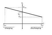
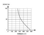
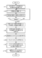
- FIG. 3 is a graph showing current-voltage characteristics during charging and discharging of a battery. It is a graph which shows deterioration degree SOH2 with respect to internal resistance. It is a flowchart in which the determination circuit calculates the deterioration degree SOH.
- FIG. 1 and FIG. 2 are block diagrams of a power supply apparatus used in the method for detecting the degree of battery deterioration according to the present invention.
- FIG. 1 is a block diagram for determining the degree of deterioration of the battery 1 mounted in the hybrid car 10A
- FIG. 2 is a block diagram for determining the degree of deterioration of the battery 1 charged by the solar battery 20.
- the present invention does not specify the use of the battery for detecting the degree of deterioration as a battery that is charged by an electric vehicle such as a hybrid car, a plug-in hybrid car, or an electric vehicle, or a solar battery.
- the battery 1 used for the electric vehicle 10 such as the hybrid car 10A or the solar battery 20 detects the full charge capacity (Ah) from the degree of deterioration, and the detected full charge capacity (Ah) and the actual dischargeable capacity (Ah). ) And the remaining capacity [SOC (%)] is calculated, and the charge / discharge current is controlled so that the remaining capacity [SOC (%)] is within a predetermined range, for example, 50% ⁇ 20%.
- the battery 1 of FIG. 1 used in the hybrid car 10A is discharged by supplying electric power to the motor 12 for driving the vehicle, and is charged by the generator 13 so that the remaining capacity is maintained at about 50%. Is done.
- the deterioration degree SOH (State of Health) of the battery 1 is detected by the determination circuit 2.
- the vehicle side includes a bidirectional power conversion device 11 that supplies electric power supplied from the battery 1 to the motor 12 and supplies electric power from the generator 13 to the battery 1.
- the bidirectional power converter 11 converts the DC power of the battery 1 into three-phase AC power and supplies it to the motor 12.
- the AC output from the generator 13 is converted into DC and supplied to the battery 1.
- the bidirectional power converter 11 is controlled by the control circuit 14 to control the power supplied from the battery 1 to the motor 12 and the charging power from the generator 13 to the battery 1.
- the control circuit 14 controls the bidirectional power converter 11 in consideration of the deterioration degree SOH of the battery 1 transmitted from the determination circuit 2 on the power supply device side via the communication line 9.
- the control circuit 14 controls the bidirectional power converter 11 in the normal mode.
- the control circuit 14 controls the bidirectional power converter 11 in the limit mode in which the charge / discharge power is smaller than in the normal mode.
- the control circuit 14 sets the bidirectional power converter 11 in the acceleration mode in which the charge / discharge power is larger than in the normal mode, or in the normal mode. To control. In this way, the control circuit 14 controls the output of the motor 12 and the generator 13 via the bidirectional power converter 11, whereby the life of the battery 1 can be brought close to the target number of years.
- the determination circuit 2 includes a current detection circuit 3 that detects a charge / discharge current flowing through the battery 1, a temperature sensor 4 that detects the temperature of the battery 1, and a voltage of the battery 1 in order to detect the deterioration degree SOH of the battery 1. And a calculation circuit 6 for detecting the deterioration degree SOH of the battery 1 from the detection values detected by these circuits.
- the determination circuit 2 incorporates an EEPROM as the memory 7, stores the deterioration degree SOH in the EEPROM, and transmits the stored deterioration degree SOH to the control circuit 14 on the vehicle side via the communication line 9.
- the current detection circuit 3 includes an A / D converter (not shown) that converts the current value of the analog signal to be detected into a digital signal at a constant sampling period.
- the current detection circuit 3 detects the charge / discharge current of the battery 1 at a constant sampling period, converts it into a digital signal, and outputs it to the arithmetic circuit 6.
- the current detection circuit 3 detects the current of the battery 1 with a sampling period of 1 msec to 10 msec.
- the sampling period at which the current detection circuit detects the current is specified as an optimum value depending on whether the current flowing through the battery changes, that is, whether it changes rapidly in a short time or slowly changes over time. For example, it may be 1 msec to 1 sec.
- the sampling period By shortening the sampling period, a rapidly changing current can be detected more accurately.
- an A / D converter that detects current and converts it into a digital signal is required to perform high-speed processing, resulting in high component costs, and the arithmetic circuit 6 also detects the detected current signal at high speed. Since it is processed, the parts cost is increased.
- the sampling period is too long, the changing current cannot be detected accurately. Therefore, the sampling period for detecting the current is specified as a period in which the changing current can be accurately detected.
- the arithmetic circuit 6 calculates the root mean square from the current value of the digital signal input from the current detection circuit 3 to detect the effective value (Irms) of the current.
- the arithmetic circuit 6 calculates the root mean square of the current value by the following equation to detect the effective value (Irms) of the current.
- Effective value (Irms) [(I 1 2 + I 2 2 + I 3 2 +... + I n 2 ) / n] 1/2
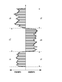
- the effective value (Irms) of the current is calculated from a plurality of detected current values detected in order. For example, the current is detected at a sampling period of 10 msec, and the effective values (I 1 , I 2 , I 3 , I 4 ,... I 100 ) of the current in the period of 1 sec are calculated as shown in FIG. .
- the deterioration degree SOH of the battery 1 is detected from each effective value (Irms) of the detected current.
- the arithmetic circuit 6 stores the deterioration degree SOH of the battery 1 with respect to the effective value (Irms) of the current in the memory 7 as a lookup table or as a function.
- the determination circuit 2 that detects the effective value (Irms) at a cycle of 1 sec stores the degree of deterioration in which the battery 1 deteriorates every 1 sec from the effective value (Irms) that flows through the battery 1 during 1 sec.
- the arithmetic circuit 6 adds the degree of deterioration stored in the memory 7 to detect the degree of deterioration SOH of the battery 1.
- the arithmetic circuit 6 detects the deterioration degree SOH from the accumulated value of the effective current value (Irms) without detecting the deterioration degree SOH of the battery 1 every time the effective value (Irms) of the current flowing through the battery 1 is detected. You can also. For example, a one-minute cumulative value of the effective value (Irms) can be detected from the product of the effective value (Irms) of current and time, and the degree of degradation SOH can be detected from this cumulative value.
- the arithmetic circuit 6 stores the deterioration level SOH of the battery 1 with respect to the accumulated value as a lookup table or a function, and detects the deterioration level SOH of the battery 1 from the stored accumulated value.
- the arithmetic circuit 6 can also specify the accumulation time of the effective current value (Irms) at the charge / discharge timing and detect the deterioration degree SOH from the accumulated value. For example, as shown in FIG. 4, the arithmetic circuit 6 accumulates effective values (Irms) in the discharge time (T 2 ) and the charge time (t 1 , t 3 ) of the battery 1, and the battery 1 The degree of degradation SOH is detected. The arithmetic circuit 6 stores the accumulated value of the effective value (Irms) of the discharge current of the battery 1 and the deterioration degree SOH with respect to the accumulated value of the effective value (Irms) of the charging current in the memory 7. The battery deterioration degree SOH is detected from the accumulated value stored in the memory 7.
- the arithmetic circuit 6 can average the current values of the digital signals detected by the current detection circuit 3 to detect an average value, and can calculate an effective value (Irms) from the average value. For example, the arithmetic circuit 6 calculates an average current by adding and averaging a plurality of current values, and calculates an effective value (Irms) from the calculated average current. Further, the arithmetic circuit 6 detects the average current by adding and averaging the current values excluding the maximum current and the minimum current from the plurality of detected current values, and calculates the effective value (Irms) from the average current. You can also. For example, the arithmetic circuit 6 can accurately detect the current of the battery 1 except for a current value that is not accurately detected due to the influence of noise.
- the determination circuit 2 can detect the deterioration degree SOH of the battery 1 from the effective value (Irms) of the charge / discharge current flowing through the battery 1 and the accumulated time exceeding the preset current limit.
- the determination circuit 2 stores the deterioration degree SOH of the battery 1 with respect to the accumulated time exceeding the limit current in the memory 7. From the deterioration degree SOH of the battery 1 with respect to the accumulated time stored in the memory 7, the determination circuit 2 The deterioration degree SOH is specified.
- the determination circuit 2 adds the degree of deterioration due to the effective value (Irms) of the charge / discharge current of the battery 1 and the degree of deterioration detected from the limit current of the battery 1 to obtain the degree of deterioration SOH of the battery 1.
- the determination circuit 2 can also detect the deterioration degree SOH of the battery 1 from the root mean square of the charge / discharge current flowing through the battery 1 and the accumulated time exceeding the preset upper and lower limit voltages.
- the determination circuit 2 stores the deterioration degree of the battery 1 with respect to the accumulated time exceeding the upper limit / lower limit voltage in the memory 7, and the deterioration of the battery 1 is determined based on the deterioration degree of the battery 1 with respect to the accumulated time stored in the memory 7.
- the degree SOH is specified.
- This determination circuit 2 adds the degree of deterioration due to the effective value (Irms) of the charging / discharging current of the battery 1 and the degree of deterioration detected from the accumulated value of the upper limit / lower limit voltage of the battery 1 to add the degree of deterioration SOH of the battery 1.
- the determination circuit 2 is detected from the deterioration degree detected from the effective value (Irms) of the current of the battery 1, the deterioration degree detected from the accumulated time exceeding the allowable current, and the accumulated time exceeding the upper limit / lower limit voltage.
- the total deterioration degree SOH can be detected by adding the deterioration degrees. Further, the determination circuit 2 can detect the deterioration degree due to the temperature of the battery 1 and detect the deterioration degree SOH in consideration of the deterioration due to the temperature.
- the determination circuit 2 can detect the deterioration degree SOH by detecting the internal resistance of the battery 1.
- the determination circuit 2 that detects the deterioration degree SOH of the battery 1 by the internal resistance detects the deterioration degree SOH from both the deterioration degree SOH1 detected from the detection value other than the internal resistance and the deterioration degree SOH2 detected from the internal resistance. be able to.
- This determination circuit 2 does not detect the deterioration degree SOH by adding the deterioration degree SOH1 and the deterioration degree SOH2, but uses the deterioration degree SOH1 and the deterioration degree SOH2 as a predetermined ratio, and the total deterioration of the battery 1 by the following formula:
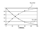
- Weight 1 and weight 2 are specified by the internal resistance of battery 1 as shown in the graph of FIG.
- the horizontal axis represents the relative value of the internal resistance of the battery 1
- the vertical axis represents weight 1 and weight 2.
- the internal resistance of the battery 1 whose lifetime has been exhausted is set to 100 in a state where the degradation degree SOH of the battery 1 is 0%.
- the weight 1 is decreased and the weight 2 is increased. This is because, in the battery 1, the internal resistance accurately specifies the deterioration degree SOH in a state where the internal resistance is large and the deterioration is advanced.
- the weight 1 and the weight 2 are specified from the internal resistance of the battery 1.
- weight 1 and weight 2 are specified from deterioration degree SOH2 specified from the internal resistance of battery 1, or weight 1 and weight 2 are specified from deterioration degree SOH determined from deterioration degree SOH1 and deterioration degree SOH2. You can also. Also in this case, the deterioration degree SOH2 is reduced or the deterioration degree SOH is reduced. In other words, the weight 1 is reduced and the weight 2 is increased as the end of life is approached.
- the determination circuit 2 calculates the effective value (Irms), temperature, and allowable current of the current of the battery 1 in a state where the ignition switch of the vehicle is turned on, that is, in the traveling state of the vehicle.
- the accumulated time exceeding, the accumulated time exceeding the upper limit / lower limit voltage, and the like are detected, and the deterioration degree SOH1 is detected every predetermined time, for example, every 10 sec.
- the timing at which the determination circuit 2 calculates the deterioration degree SOH1 is not specified as 10 seconds, but is shorter or longer than 10 seconds, for example, 0.1 sec to 1 minute, preferably 0.3 sec to 30 sec, more preferably, It can also be 0.3 sec to 10 sec.
- the determination circuit 2 detects the average temperature of the battery 1 every several hours, for example, every 1 to 5 hours, and calculates the deterioration degree SOH1.
- the battery 1 charged with the solar battery 20 always detects the deterioration degree SOH1 of the battery 1 at a constant cycle, for example, every 1 sec to 1 minute.
- the determination circuit 2 detects the internal resistance of the battery 1 and detects the deterioration degree SOH2 from the internal resistance.
- An equivalent circuit of the battery 1 having internal resistance is shown in FIG.
- the deterioration degree SOH2 of the battery 1 with respect to the internal resistance of the battery 1 is measured in advance and stored in the lookup table of the determination circuit 2, or the determination circuit 2 stores the deterioration degree SOH2 with respect to the internal resistance as a function.
- FIG. 8 illustrates the degradation degree SOH2 with respect to the internal resistance, which is stored in the lookup table or stored as a function. In the battery having the characteristics shown in this figure, when the internal resistance is 300 m ⁇ , the deterioration degree SOH2 is 60%.
- the determination circuit 2 that detects the deterioration degree SOH from the deterioration degree SOH1 and the deterioration degree SOH2 specifies the weight 1 and the weight 2 from the detected deterioration degree SOH1 and deterioration degree SOH2, and determines the deterioration degree SOH of the battery 1.
- the filtering by temperature detects the battery temperature when detecting the internal resistance of the battery 1 and converts the detected internal resistance into an internal resistance at a set temperature as a function of temperature.
- the determination circuit 2 that filters the internal resistance stores the change of the internal resistance with respect to the temperature as a function or in a lookup table. From this stored value, the internal resistance is filtered and corrected to the internal resistance at the set temperature.
- Step n 3] The current and temperature at which the battery 1 is charged and discharged, and the internal resistance are measured and filtered.
- Step n 9]
- the determination circuit 2 calculates the degree of degradation SOH from the weight 1 and the degree of degradation SOH1, and from the weight 2 and the degree of degradation SOH2.
- Step n 10] In order to bring the deterioration degree SOH1 closer to the deterioration degree SOH, the deterioration degree SOH1 is corrected from the calculated deterioration degree SOH.
- the determination circuit 2 determines the deterioration level SOH of the battery 1 as described above, and transmits the determined deterioration level SOH to the vehicle-side control circuit 14 via the communication line 9. By detecting such a deterioration degree SOH, the life of the battery 1 can be known. Further, various characteristics in each deterioration degree SOH (for example, the relationship between the voltage in the deterioration degree SOH and the remaining capacity [SOC (%)] of the battery, the full charge capacity in the deterioration degree SOH, etc.) are stored in advance. Such stored characteristics can be used in accordance with the degree of degradation SOH at the time point determined and detected.
- the determination circuit 2 stores the full charge capacity (Ah) with respect to the deterioration degree SOH of the battery 1 in a lookup table or as a function.
- the full charge capacity (Ah) is detected from the degree of deterioration SOH, the battery 1 charged by the electric vehicle 10 or the solar battery 20 has a remaining capacity [Ah] from the ratio of the dischargeable capacity (Ah) to the full charge capacity (Ah). SOC (%)] is calculated.
- the dischargeable capacity (Ah) is calculated from the integrated value of the charge / discharge current of the battery 1.
- the dischargeable capacity (Ah) is detected by adding the integrated value of the charging current of the battery 1 and subtracting the integrated value of the discharging current.
- the remaining capacity [SOC (%)] is detected, for example, the remaining capacity [SOC (%)] is set to 30% to 70%, or 20 so that the remaining capacity [SOC (%)] is within a predetermined range.
- the charging / discharging current so as to be in the range of from 80% to 80%, or from 10% to 90%, the deterioration of the battery 1 can be reduced and the life can be extended.
- the maximum current flowing through the battery 1 is controlled to be small or the maximum voltage when charging is lowered in accordance with the deterioration degree SOH of the battery 1. It is also possible to charge and discharge while protecting.
- the method for detecting the degree of deterioration of the battery according to the present invention can be suitably used as a power supply device for a plug-in hybrid electric vehicle, a hybrid electric vehicle, an electric vehicle or the like that can switch between the EV traveling mode and the HEV traveling mode.
- a backup power supply device that can be mounted on a rack of a computer server, a backup power supply device for a wireless base station such as a mobile phone, a power storage device for home use and a factory, a power supply for a street light, etc. Also, it can be used as appropriate for applications such as a backup power source such as a traffic light.
Landscapes
- Engineering & Computer Science (AREA)
- Power Engineering (AREA)
- Transportation (AREA)
- Mechanical Engineering (AREA)
- Life Sciences & Earth Sciences (AREA)
- Sustainable Development (AREA)
- Sustainable Energy (AREA)
- General Physics & Mathematics (AREA)
- Physics & Mathematics (AREA)
- Manufacturing & Machinery (AREA)
- Chemical & Material Sciences (AREA)
- Chemical Kinetics & Catalysis (AREA)
- Electrochemistry (AREA)
- General Chemical & Material Sciences (AREA)
- Secondary Cells (AREA)
- Charge And Discharge Circuits For Batteries Or The Like (AREA)
Abstract
Description
以上の劣化度の検出方法は、実効値(Irms)の累積値から劣化度SOHを検出するので、電流の実効値(Irms)から電池の劣化度SOHを検出する回数を少なくして、劣化度SOHを検出できる。すなわち、実効値(Irms)を累積する時間を、実効値(Irms)を検出する時間よりも長くすることで、劣化度SOHを検出する回数を少なくして劣化度SOHを検出できる。
以上の劣化度の検出方法は、あらかじめ設定している一定の時間において、電流の実効値(Irms)を累積して劣化度SOHを検出するので、簡単に劣化度SOHを検出できる。
以上の劣化度の検出方法は、電池を充放電する状態で最適な時間を特定して、電流の実効値(Irms)を累積するので、簡単で正確に劣化度SOHを検出できる。
以上の検出方法は、電流の実効値(Irms)のみでなく、制限電流を越えた累積時間の両方で劣化度SOHを検出するので、より正確に劣化度SOHを検出できる。
以上の検出方法は、電流の実効値(Irms)に加えて、上限・下限電圧を越えた累積時間をも考慮して劣化度SOHを検出するので、より正確に劣化度SOHを検出できる。
以上の検出方法は、電池の電流を1msec~1secのサンプリング周期で検出して二乗平均平方根から実効値(Irms)を検出するので、電池に流れる電流の変化から正確に実効値(Irms)を検出して、劣化度SOHを正確に検出できる。
以上の劣化度の検出方法は、電池の劣化度SOHから満充電容量を正確に検出し、検出される満充電容量から電池を正確に一定の残容量範囲にコントロールし、このことによって電池の過充電や過放電を確実に防止して寿命を長くできる特徴がある。
以上の検出方法は、モータに電力を供給する電池の満充電容量を劣化度SOHから検出し、検出される満充電容量から電池の過充電や過放電を防止して劣化を防止して、電池を長寿命に使用できる特徴がある。
以上の検出方法は、太陽電池で充電される電池の満充電容量を劣化度SOHから正確に検出し、検出される満充電容量から電池の過充電や過放電を防止して劣化を防止し、高価な電池を長寿命に使用できる特徴がある。
実効値(Irms)=[(I1 2+I2 2+I3 2+・・・・+In 2)/n]1/2
劣化度SOH=ウェイト1×劣化度SOH1+ウェイト2×劣化度SOH2
ただし、ウェイト1+ウェイト2=1である。
劣化度SOH1(%)=前回の劣化度SOH1(%)-電流や温度などによる劣化度SOH1(%)
電池1の劣化は、電池温度が高いほど進行する。したがって、判定回路2は、電流のみでなく電池温度により電池1が単位時間に劣化する劣化度をメモリ7に記憶している。判定回路2は、メモリ7に記憶される温度に対する劣化度から、時間の経過とともに劣化する電池1の劣化度SOHを検出する。
電池1の開放電圧をVoとし、電流Iのときに電圧をVLとすれば、
VL=Vo-R0×I
この式から、
R0=(Vo-VL)/I で演算される。
[n=1のステップ]
このステップで、判定回路2は内蔵するメモリ7のデータから、劣化度SOH1、劣化度SOH2、劣化度SOHを初期化する。
[n=2のステップ]
このステップで、判定回路2は電池1の電流と電圧から内部抵抗を演算する。このとき、温度によるフィルタリングをして、測定精度を高くする。内部抵抗が温度により変化するからである。温度によるフィルタリングは、電池1の内部抵抗を検出するときの電池温度を検出し、検出される内部抵抗を温度を関数として設定温度における内部抵抗に変換する。内部抵抗をフィルタリングする判定回路2は、温度に対する内部抵抗の変化を、関数として、あるいはルックアップテーブルに記憶している。この記憶値から、内部抵抗を設定温度の内部抵抗にフィルタリングして補正する。
[n=3のステップ]
電池1が充放電される電流と温度と、さらに内部抵抗を測定し、これをフィルタリングする。
[n=4のステップ]
1sec経過するまで、n=2~4のステップをループする。
[n=5のステップ]
1sec経過すると、このステップにおいて、1sec間における電流の実効値(Irms)、平均温度、内部抵抗を演算する。
[n=6のステップ]
このステップで、判定回路2は、1sec間における電流の実効値(Irms)と電池の平均温度から劣化度SOH1を計算する。
[n=7のステップ]
さらに、判定回路2は、記憶しているルックアップテーブルや関数に基づいて、内部抵抗から劣化度SOH2を演算する。
[n=8のステップ]
このステップで、判定回路2は、劣化度SOH1と劣化度SOH2のウェイト1とウェイト2を特定する。ウェイト1とウェイト2は、図5から特定する。
[n=9のステップ]
判定回路2は、ウェイト1及び劣化度SOH1と、ウェイト2及び劣化度SOH2から劣化度SOHを演算する。
[n=10のステップ]
劣化度SOH1を劣化度SOHに近づけるために、演算された劣化度SOHから劣化度SOH1を補正する。
このような劣化度SOHを検出することにより、電池1の寿命を知ることができる。また、各劣化度SOHにおける各種の特性(たとえば、その劣化度SOHにおける電圧と電池の残容量[SOC(%)]との関係、その劣化度SOHにおける満充電容量等)を予め保存しておき、判定、検出されたその時点における劣化度SOHに応じて、このような保存された特性を利用することができる。
2…判定回路
3…電流検出回路
4…温度センサ
5…電圧検出回路
6…演算回路
7…メモリ
9…通信回線
10…電動車両 10A…ハイブリッドカー
11…双方向電力変換装置
12…モータ
13…発電機
14…制御回路
20…太陽電池
Claims (10)
- 電池に流れる充放電の電流を検出して、充放電の電流から電池の劣化度を検出する方法であって、
電池に流れる充放電電流の二乗平均平方根で示される電流の実効値(Irms)から電池の劣化度SOHを検出することを特徴とする電池の劣化度の検出方法。 - 電池に流れる充放電電流の実効値(Irms)の累積値から電池の劣化度SOHを検出する請求項1に記載される電池の劣化度の検出方法。
- 電池に流れる充放電電流の実効値(Irms)を、一定の時間で累積して累積値を検出する請求項2に記載される電池の劣化度の検出方法。
- 電池に流れる充放電電流の実効値(Irms)を累積する時間を、充放電のタイミングで特定して、累積値から劣化度SOHを検出する請求項2に記載される電池の劣化度の検出方法。
- 電池に流れる充放電電流の実効値(Irms)と、あらかじめ設定している制限電流を越えた累積時間とから電池の劣化度SOHを検出する請求項1ないし4のいずれかに記載される電池の劣化度の検出方法。
- 電池に流れる充放電電流の二乗平均平方根と、あらかじめ設定している上限・下限電圧を越えた累積時間とから電池の劣化度SOHを検出する請求項1ないし5のいずれかに記載される電池の劣化度の検出方法。
- 電池を充放電する電流を1msecないし1secのサンプリング周期で検出して二乗平均平方根を検出する請求項1ないし6のいずれかに記載される電池の劣化度の検出方法。
- 電池が、あらかじめ設定している残容量[SOC(%)]の範囲に制御して充放電される用途に使用される請求項1ないし7のいずれかに記載される電池の劣化度の検出方法。
- 電池が、車両を走行させるモータに電力を供給する電池である請求項8に記載される電池の劣化度の検出方法。
- 電池が、太陽電池の電力を蓄える電源に使用される請求項8に記載される電池の劣化度の検出方法。
Priority Applications (2)
| Application Number | Priority Date | Filing Date | Title |
|---|---|---|---|
| JP2012551031A JPWO2012091077A1 (ja) | 2010-12-28 | 2011-12-27 | 電池の劣化度の検出方法 |
| US13/976,679 US9176195B2 (en) | 2010-12-28 | 2011-12-27 | Method of detecting battery degradation level |
Applications Claiming Priority (2)
| Application Number | Priority Date | Filing Date | Title |
|---|---|---|---|
| JP2010294055 | 2010-12-28 | ||
| JP2010-294055 | 2010-12-28 |
Publications (1)
| Publication Number | Publication Date |
|---|---|
| WO2012091077A1 true WO2012091077A1 (ja) | 2012-07-05 |
Family
ID=46383165
Family Applications (1)
| Application Number | Title | Priority Date | Filing Date |
|---|---|---|---|
| PCT/JP2011/080350 Ceased WO2012091077A1 (ja) | 2010-12-28 | 2011-12-27 | 電池の劣化度の検出方法 |
Country Status (3)
| Country | Link |
|---|---|
| US (1) | US9176195B2 (ja) |
| JP (1) | JPWO2012091077A1 (ja) |
| WO (1) | WO2012091077A1 (ja) |
Cited By (18)
| Publication number | Priority date | Publication date | Assignee | Title |
|---|---|---|---|---|
| WO2014064507A1 (en) * | 2012-10-25 | 2014-05-01 | Toyota Jidosha Kabushiki Kaisha | Battery system |
| JP2014107901A (ja) * | 2012-11-26 | 2014-06-09 | Hitachi Ltd | 移動体の電力管理システム |
| US20140184166A1 (en) * | 2011-06-10 | 2014-07-03 | Keiichiro Ohkawa | Battery control device and battery system |
| JP2014193094A (ja) * | 2013-03-28 | 2014-10-06 | Mazda Motor Corp | 車両用電源制御装置 |
| CN104467087A (zh) * | 2014-11-28 | 2015-03-25 | 刘尚爱 | 一种智能太阳能充电系统 |
| CN104656039A (zh) * | 2015-02-04 | 2015-05-27 | 上海交通大学 | 一种充电电池使用寿命的检测方法及系统 |
| JP2015104215A (ja) * | 2013-11-25 | 2015-06-04 | 三菱重工業株式会社 | 劣化量推定装置、劣化量推定方法、及びプログラム |
| JP2015111104A (ja) * | 2013-10-31 | 2015-06-18 | 三菱自動車工業株式会社 | 電池劣化監視システム |
| WO2015098012A1 (ja) * | 2013-12-27 | 2015-07-02 | 三洋電機株式会社 | 制御システム、車両用電源装置 |
| DE102014210197A1 (de) | 2014-05-28 | 2015-12-03 | Robert Bosch Gmbh | Verfahren zum Batteriemanagement und Batteriemanagementsystem |
| CN105676134A (zh) * | 2016-01-08 | 2016-06-15 | 中国第一汽车股份有限公司 | 一种车用锂离子动力电池的soh估算方法 |
| JP2017534050A (ja) * | 2014-10-17 | 2017-11-16 | ルノー エス.ア.エス. | 1組の据置バッテリーの欠陥を診断するための方法 |
| JPWO2016129212A1 (ja) * | 2015-02-13 | 2017-12-21 | パナソニックIpマネジメント株式会社 | 電池状態推定装置、および電源装置 |
| CN108594123A (zh) * | 2018-03-09 | 2018-09-28 | 宁德时代新能源科技股份有限公司 | 电池包soh检测方法、装置和设备 |
| CN110673036A (zh) * | 2019-07-24 | 2020-01-10 | 广州中国科学院计算机网络信息中心 | 基于obd计算技术的车辆故障预警方法及系统 |
| CN110861534A (zh) * | 2019-11-27 | 2020-03-06 | 安徽江淮汽车集团股份有限公司 | 电动汽车修正方法、装置、设备及存储介质 |
| JPWO2019026142A1 (ja) * | 2017-07-31 | 2020-07-27 | 日産自動車株式会社 | 劣化状態演算方法及び劣化状態演算装置 |
| JP2024041504A (ja) * | 2022-09-14 | 2024-03-27 | カワサキモータース株式会社 | バッテリ管理方法、バッテリ管理プログラム、記憶制御装置および移動体 |
Families Citing this family (33)
| Publication number | Priority date | Publication date | Assignee | Title |
|---|---|---|---|---|
| US20120179435A1 (en) * | 2011-01-10 | 2012-07-12 | Ford Global Technologies, Llc | Method For Determining A Power Capability For A Battery |
| US9735591B2 (en) * | 2012-02-27 | 2017-08-15 | Kyocera Corporation | Control apparatus, control system, and storage battery control method |
| JP5596083B2 (ja) * | 2012-06-26 | 2014-09-24 | Imv株式会社 | リチウムイオン二次電池の劣化診断装置 |
| JP5798594B2 (ja) * | 2013-06-18 | 2015-10-21 | トヨタ自動車株式会社 | 充電制御装置 |
| CN103558556B (zh) * | 2013-10-31 | 2016-02-03 | 重庆长安汽车股份有限公司 | 一种动力电池soh估算方法 |
| US9547045B2 (en) * | 2014-02-04 | 2017-01-17 | Gm Global Technology Operations, Llc | Methods and systems for determining a characteristic of a vehicle energy source |
| JP6316690B2 (ja) * | 2014-07-17 | 2018-04-25 | 日立オートモティブシステムズ株式会社 | 電池状態検知装置、二次電池システム、電池状態検知プログラム、電池状態検知方法 |
| JP6324248B2 (ja) * | 2014-07-17 | 2018-05-16 | 日立オートモティブシステムズ株式会社 | 電池状態検知装置、二次電池システム、電池状態検知プログラム、電池状態検知方法 |
| US10232732B2 (en) | 2015-01-27 | 2019-03-19 | Ford Global Technologies, Llc | System and method for battery control using RMS current |
| DE102015205252A1 (de) * | 2015-03-24 | 2016-09-29 | Robert Bosch Gmbh | Batteriesystem und Verfahren zum Betreiben eines Batteriesystems |
| US10527681B2 (en) * | 2015-03-31 | 2020-01-07 | Gs Yuasa International Ltd. | Degradation estimator for energy storage device, energy storage apparatus, input-output control device for energy storage device, and method for controlling input and output of energy storage device |
| US11131706B2 (en) * | 2015-12-08 | 2021-09-28 | International Business Machines Corporation | Degradation monitoring of semiconductor chips |
| US10107864B2 (en) | 2016-04-11 | 2018-10-23 | Inventus Holdings, Llc | Step-time battery degradation determination |
| FR3051916B1 (fr) * | 2016-05-31 | 2020-07-10 | Renault S.A.S. | Procede d'estimation de l'etat de sante d'une batterie |
| EP3673554B1 (de) * | 2017-08-25 | 2021-09-29 | SEW-EURODRIVE GmbH & Co. KG | Verfahren zur bestimmung des ladezustandes einer energiespeicherzelle und energiespeichersystem |
| US20190094306A1 (en) * | 2017-09-25 | 2019-03-28 | Fujitsu Limited | Battery's residual energy measurement circuit and sensor node |
| US11697355B2 (en) * | 2018-08-22 | 2023-07-11 | Ford Global Technologies, Llc | Electrified vehicle electrical distribution system component protection systems and methods |
| US11157055B2 (en) * | 2018-10-05 | 2021-10-26 | Toyota Motor North America, Inc. | Apparatus, methods, and systems for tracking vehicle battery usage with a blockchain |
| DE102019108387A1 (de) * | 2019-04-01 | 2020-10-01 | Bayerische Motoren Werke Aktiengesellschaft | Verfahren zum Bestimmen einer Belastungshistorie eines mit einer elektrischen Maschine angetriebenen Fahrzeugs, Vorrichtung sowie Fahrzeug |
| US12296714B2 (en) * | 2019-06-12 | 2025-05-13 | Mitsubishi Electric Corporation | Charge and discharge control device and charge and discharge control method including first, second, and third charge level ranges |
| DE102019211142A1 (de) * | 2019-07-26 | 2021-01-28 | Siemens Mobility GmbH | Verfahren zum Betreiben eines Schienenfahrzeugs und Schienenfahrzeug |
| CN112305439B (zh) * | 2019-07-31 | 2022-01-07 | 比亚迪股份有限公司 | 电池寿命测试方法、装置及可读存储介质 |
| US11340678B2 (en) * | 2020-09-22 | 2022-05-24 | Dell Products L.P. | System and method of determining power values of an information handling system that includes one or more batteries |
| DE102021131083A1 (de) * | 2020-11-30 | 2022-06-02 | Steering Solutions Ip Holding Corporation | Diagnose eines zustands einer eingangsenergie für eine elektrische servolenkung |
| US12098708B2 (en) * | 2021-01-19 | 2024-09-24 | General Electric Renovables Espana, S.L. | Systems and methods for operating a power generating asset |
| US20220250504A1 (en) * | 2021-02-09 | 2022-08-11 | Ford Global Technologies, Llc | Recovery strategies for battery capacity data loss and control related to same |
| US12510603B2 (en) * | 2021-04-29 | 2025-12-30 | The Board Of Trustees Of The University Of Alabama | Determining state-of-health of an energy storage device using complex impedance spectrum |
| KR102913839B1 (ko) * | 2021-09-08 | 2026-01-16 | 컨템포러리 엠퍼렉스 테크놀로지 (홍콩) 리미티드 | 파워 배터리 충전 방법 및 배터리 관리 시스템 |
| US20230208169A1 (en) * | 2021-12-29 | 2023-06-29 | Auto Motive Power Inc. | Technique Using a Battery Charger and Battery Management System to Detect Cell Degradation and Pack Imminent Failures |
| JP2024038730A (ja) * | 2022-09-08 | 2024-03-21 | 株式会社Subaru | バッテリ管理装置 |
| CN116118567B (zh) * | 2022-11-17 | 2025-12-12 | 深圳市元征科技股份有限公司 | 电池管理方法、装置、终端设备及存储介质 |
| US20240286506A1 (en) * | 2023-02-28 | 2024-08-29 | Delphi Technologies Ip Limited | On-board charger with simultaneous charge and discharge capability |
| US20250377412A1 (en) * | 2024-06-07 | 2025-12-11 | Cox Automotive, Inc. | System and methods for determining a status of a battery pack of a vehicle |
Citations (2)
| Publication number | Priority date | Publication date | Assignee | Title |
|---|---|---|---|---|
| JP2008122165A (ja) * | 2006-11-09 | 2008-05-29 | Sanyo Electric Co Ltd | 電池の劣化度の検出方法 |
| JP2009207312A (ja) * | 2008-02-28 | 2009-09-10 | Sanyo Electric Co Ltd | 車両用の電源装置とその電流制御方法 |
Family Cites Families (6)
| Publication number | Priority date | Publication date | Assignee | Title |
|---|---|---|---|---|
| US3775675A (en) * | 1972-06-15 | 1973-11-27 | Westinghouse Electric Corp | Apparatus for indicating when current exceeds a predetermined level and when said level is exceeded for a predetermined period of time |
| US3940679A (en) * | 1974-06-18 | 1976-02-24 | Textron, Inc. | Nickel-cadmium battery monitor |
| JPH06342045A (ja) * | 1993-05-31 | 1994-12-13 | Omron Corp | バッテリーの寿命計測装置 |
| JP4787241B2 (ja) * | 2004-04-06 | 2011-10-05 | コバシス, エルエルシー | バッテリ充電状態推定器 |
| JP2008228492A (ja) | 2007-03-14 | 2008-09-25 | Sanyo Electric Co Ltd | リチウムイオン二次電池の充電方法 |
| WO2012091076A1 (ja) * | 2010-12-28 | 2012-07-05 | 三洋電機株式会社 | 電池の劣化度の検出方法 |
-
2011
- 2011-12-27 JP JP2012551031A patent/JPWO2012091077A1/ja active Pending
- 2011-12-27 WO PCT/JP2011/080350 patent/WO2012091077A1/ja not_active Ceased
- 2011-12-27 US US13/976,679 patent/US9176195B2/en active Active
Patent Citations (2)
| Publication number | Priority date | Publication date | Assignee | Title |
|---|---|---|---|---|
| JP2008122165A (ja) * | 2006-11-09 | 2008-05-29 | Sanyo Electric Co Ltd | 電池の劣化度の検出方法 |
| JP2009207312A (ja) * | 2008-02-28 | 2009-09-10 | Sanyo Electric Co Ltd | 車両用の電源装置とその電流制御方法 |
Cited By (32)
| Publication number | Priority date | Publication date | Assignee | Title |
|---|---|---|---|---|
| US20140184166A1 (en) * | 2011-06-10 | 2014-07-03 | Keiichiro Ohkawa | Battery control device and battery system |
| US9641011B2 (en) * | 2011-06-10 | 2017-05-02 | Hitachi Automotive Systems, Ltd. | Battery control device adapting the battery current limit by decreasing the stored current limit by comparing it with the measured battery current |
| WO2014064507A1 (en) * | 2012-10-25 | 2014-05-01 | Toyota Jidosha Kabushiki Kaisha | Battery system |
| CN104488130B (zh) * | 2012-10-25 | 2017-10-10 | 丰田自动车株式会社 | 电池系统 |
| CN104488130A (zh) * | 2012-10-25 | 2015-04-01 | 丰田自动车株式会社 | 电池系统 |
| JP2014107901A (ja) * | 2012-11-26 | 2014-06-09 | Hitachi Ltd | 移動体の電力管理システム |
| JP2014193094A (ja) * | 2013-03-28 | 2014-10-06 | Mazda Motor Corp | 車両用電源制御装置 |
| JP2015111104A (ja) * | 2013-10-31 | 2015-06-18 | 三菱自動車工業株式会社 | 電池劣化監視システム |
| JP2015104215A (ja) * | 2013-11-25 | 2015-06-04 | 三菱重工業株式会社 | 劣化量推定装置、劣化量推定方法、及びプログラム |
| US9963043B2 (en) | 2013-12-27 | 2018-05-08 | Sanyo Electric Co., Ltd. | Control system and vehicle power supply |
| WO2015098012A1 (ja) * | 2013-12-27 | 2015-07-02 | 三洋電機株式会社 | 制御システム、車両用電源装置 |
| CN105848978A (zh) * | 2013-12-27 | 2016-08-10 | 三洋电机株式会社 | 控制系统、车辆用电源装置 |
| CN105848978B (zh) * | 2013-12-27 | 2018-10-23 | 三洋电机株式会社 | 控制系统、车辆用电源装置 |
| DE102014210197A1 (de) | 2014-05-28 | 2015-12-03 | Robert Bosch Gmbh | Verfahren zum Batteriemanagement und Batteriemanagementsystem |
| WO2015180910A1 (de) | 2014-05-28 | 2015-12-03 | Robert Bosch Gmbh | Verfahren zum batteriemanagement und batteriemanagementsystem |
| CN106385799B (zh) * | 2014-05-28 | 2019-07-26 | 罗伯特·博世有限公司 | 用于电池组管理的方法和电池组管理系统 |
| CN106385799A (zh) * | 2014-05-28 | 2017-02-08 | 罗伯特·博世有限公司 | 用于电池组管理的方法和电池组管理系统 |
| US10147980B2 (en) | 2014-05-28 | 2018-12-04 | Robert Bosch Gmbh | Method for battery management and battery management system |
| JP2017534050A (ja) * | 2014-10-17 | 2017-11-16 | ルノー エス.ア.エス. | 1組の据置バッテリーの欠陥を診断するための方法 |
| CN104467087A (zh) * | 2014-11-28 | 2015-03-25 | 刘尚爱 | 一种智能太阳能充电系统 |
| CN104656039A (zh) * | 2015-02-04 | 2015-05-27 | 上海交通大学 | 一种充电电池使用寿命的检测方法及系统 |
| JPWO2016129212A1 (ja) * | 2015-02-13 | 2017-12-21 | パナソニックIpマネジメント株式会社 | 電池状態推定装置、および電源装置 |
| CN105676134A (zh) * | 2016-01-08 | 2016-06-15 | 中国第一汽车股份有限公司 | 一种车用锂离子动力电池的soh估算方法 |
| JPWO2019026142A1 (ja) * | 2017-07-31 | 2020-07-27 | 日産自動車株式会社 | 劣化状態演算方法及び劣化状態演算装置 |
| CN108594123A (zh) * | 2018-03-09 | 2018-09-28 | 宁德时代新能源科技股份有限公司 | 电池包soh检测方法、装置和设备 |
| CN108594123B (zh) * | 2018-03-09 | 2020-06-23 | 宁德时代新能源科技股份有限公司 | 电池包soh检测方法、装置和设备 |
| CN110673036A (zh) * | 2019-07-24 | 2020-01-10 | 广州中国科学院计算机网络信息中心 | 基于obd计算技术的车辆故障预警方法及系统 |
| CN110673036B (zh) * | 2019-07-24 | 2021-09-28 | 广州中国科学院计算机网络信息中心 | 基于obd计算技术的车辆故障预警方法及系统 |
| CN110861534A (zh) * | 2019-11-27 | 2020-03-06 | 安徽江淮汽车集团股份有限公司 | 电动汽车修正方法、装置、设备及存储介质 |
| CN110861534B (zh) * | 2019-11-27 | 2021-03-16 | 安徽江淮汽车集团股份有限公司 | 电动汽车修正方法、装置、设备及存储介质 |
| JP2024041504A (ja) * | 2022-09-14 | 2024-03-27 | カワサキモータース株式会社 | バッテリ管理方法、バッテリ管理プログラム、記憶制御装置および移動体 |
| JP7834618B2 (ja) | 2022-09-14 | 2026-03-24 | カワサキモータース株式会社 | バッテリ管理方法および移動体 |
Also Published As
| Publication number | Publication date |
|---|---|
| US20130271148A1 (en) | 2013-10-17 |
| JPWO2012091077A1 (ja) | 2014-06-05 |
| US9176195B2 (en) | 2015-11-03 |
Similar Documents
| Publication | Publication Date | Title |
|---|---|---|
| JP6073686B2 (ja) | 電池の劣化度の検出方法 | |
| WO2012091077A1 (ja) | 電池の劣化度の検出方法 | |
| JP5348987B2 (ja) | 電池の劣化度の検出方法 | |
| US7944178B2 (en) | Fully-charged battery capacity detection method | |
| JP5389425B2 (ja) | ハイブリッドカーの充放電制御方法 | |
| JP5621818B2 (ja) | 蓄電システムおよび均等化方法 | |
| JP5960063B2 (ja) | 電池の満充電容量検出方法 | |
| US9444267B2 (en) | Cell voltage equalizer for multi-cell battery pack which determines the waiting time between equalization operations based on the voltage difference and the state of charge level | |
| JP6132314B2 (ja) | 電源装置、電源装置を備える車両並びに蓄電装置、及び電池の残容量の検出方法 | |
| JP4884945B2 (ja) | 充電状態予測プログラム、架線レス交通システム及びその充電方法 | |
| US9575137B2 (en) | Control apparatus, control method, power supply system, and electric-powered vehicle | |
| JP2009195081A (ja) | 充電制御回路、及びこれを備える充電装置、電池パック | |
| JP2010098866A (ja) | 不均衡判定回路、不均衡低減回路、電池電源装置、及び不均衡判定方法 | |
| WO2013008814A1 (ja) | 電源装置及び電源装置を備える車両 | |
| JP2010200574A (ja) | 自己診断回路、及び電源装置 | |
| JPWO2012140776A1 (ja) | 充電制御装置 | |
| JP5772615B2 (ja) | 蓄電システム | |
| US20250158423A1 (en) | Battery system |
Legal Events
| Date | Code | Title | Description |
|---|---|---|---|
| 121 | Ep: the epo has been informed by wipo that ep was designated in this application |
Ref document number: 11852402 Country of ref document: EP Kind code of ref document: A1 |
|
| ENP | Entry into the national phase |
Ref document number: 2012551031 Country of ref document: JP Kind code of ref document: A |
|
| WWE | Wipo information: entry into national phase |
Ref document number: 13976679 Country of ref document: US |
|
| NENP | Non-entry into the national phase |
Ref country code: DE |
|
| 122 | Ep: pct application non-entry in european phase |
Ref document number: 11852402 Country of ref document: EP Kind code of ref document: A1 |