WO2012091085A1 - ドリル - Google Patents
ドリル Download PDFInfo
- Publication number
- WO2012091085A1 WO2012091085A1 PCT/JP2011/080374 JP2011080374W WO2012091085A1 WO 2012091085 A1 WO2012091085 A1 WO 2012091085A1 JP 2011080374 W JP2011080374 W JP 2011080374W WO 2012091085 A1 WO2012091085 A1 WO 2012091085A1
- Authority
- WO
- WIPO (PCT)
- Prior art keywords
- drill
- pyramid shape
- polygonal pyramid
- tip
- polygonal
- Prior art date
- Legal status (The legal status is an assumption and is not a legal conclusion. Google has not performed a legal analysis and makes no representation as to the accuracy of the status listed.)
- Ceased
Links
Images


Classifications
-
- B—PERFORMING OPERATIONS; TRANSPORTING
- B23—MACHINE TOOLS; METAL-WORKING NOT OTHERWISE PROVIDED FOR
- B23B—TURNING; BORING
- B23B51/00—Tools for drilling machines
-
- B—PERFORMING OPERATIONS; TRANSPORTING
- B23—MACHINE TOOLS; METAL-WORKING NOT OTHERWISE PROVIDED FOR
- B23B—TURNING; BORING
- B23B2251/00—Details of tools for drilling machines
- B23B2251/04—Angles, e.g. cutting angles
-
- B—PERFORMING OPERATIONS; TRANSPORTING
- B23—MACHINE TOOLS; METAL-WORKING NOT OTHERWISE PROVIDED FOR
- B23B—TURNING; BORING
- B23B2251/00—Details of tools for drilling machines
- B23B2251/08—Side or plan views of cutting edges
- B23B2251/085—Discontinuous or interrupted cutting edges
-
- B—PERFORMING OPERATIONS; TRANSPORTING
- B23—MACHINE TOOLS; METAL-WORKING NOT OTHERWISE PROVIDED FOR
- B23B—TURNING; BORING
- B23B2251/00—Details of tools for drilling machines
- B23B2251/18—Configuration of the drill point
-
- B—PERFORMING OPERATIONS; TRANSPORTING
- B23—MACHINE TOOLS; METAL-WORKING NOT OTHERWISE PROVIDED FOR
- B23B—TURNING; BORING
- B23B2251/00—Details of tools for drilling machines
- B23B2251/46—Drills having a centre free from cutting edges or with recessed cutting edges
-
- B—PERFORMING OPERATIONS; TRANSPORTING
- B23—MACHINE TOOLS; METAL-WORKING NOT OTHERWISE PROVIDED FOR
- B23B—TURNING; BORING
- B23B2265/00—Details of general geometric configurations
- B23B2265/32—Polygonal
- B23B2265/324—Pentagonal
-
- B—PERFORMING OPERATIONS; TRANSPORTING
- B23—MACHINE TOOLS; METAL-WORKING NOT OTHERWISE PROVIDED FOR
- B23B—TURNING; BORING
- B23B2265/00—Details of general geometric configurations
- B23B2265/32—Polygonal
- B23B2265/326—Hexagonal
-
- B—PERFORMING OPERATIONS; TRANSPORTING
- B23—MACHINE TOOLS; METAL-WORKING NOT OTHERWISE PROVIDED FOR
- B23B—TURNING; BORING
- B23B51/00—Tools for drilling machines
- B23B51/02—Twist drills
-
- Y—GENERAL TAGGING OF NEW TECHNOLOGICAL DEVELOPMENTS; GENERAL TAGGING OF CROSS-SECTIONAL TECHNOLOGIES SPANNING OVER SEVERAL SECTIONS OF THE IPC; TECHNICAL SUBJECTS COVERED BY FORMER USPC CROSS-REFERENCE ART COLLECTIONS [XRACs] AND DIGESTS
- Y10—TECHNICAL SUBJECTS COVERED BY FORMER USPC
- Y10T—TECHNICAL SUBJECTS COVERED BY FORMER US CLASSIFICATION
- Y10T408/00—Cutting by use of rotating axially moving tool
- Y10T408/89—Tool or Tool with support
- Y10T408/899—Having inversely angled cutting edge
-
- Y—GENERAL TAGGING OF NEW TECHNOLOGICAL DEVELOPMENTS; GENERAL TAGGING OF CROSS-SECTIONAL TECHNOLOGIES SPANNING OVER SEVERAL SECTIONS OF THE IPC; TECHNICAL SUBJECTS COVERED BY FORMER USPC CROSS-REFERENCE ART COLLECTIONS [XRACs] AND DIGESTS
- Y10—TECHNICAL SUBJECTS COVERED BY FORMER USPC
- Y10T—TECHNICAL SUBJECTS COVERED BY FORMER US CLASSIFICATION
- Y10T408/00—Cutting by use of rotating axially moving tool
- Y10T408/89—Tool or Tool with support
- Y10T408/909—Having peripherally spaced cutting edges
- Y10T408/9095—Having peripherally spaced cutting edges with axially extending relief channel
- Y10T408/9097—Spiral channel
Definitions
- the present invention relates to a drill used for, for example, machining.
- a chisel edge formed at the tip is known. Since the chisel edge has a wedge shape with a very small rake angle and a small chip pocket, a very large thrust load is generated as compared with the cutting edge.
- a drill having a chisel edge generates a component force in a direction orthogonal to the thrust, so that the biting property and the centripetal force are lowered. Therefore, a technique for improving chip dischargeability from the center by so-called thinning is performed by shortening the chisel edge and providing a rake angle.
- Patent Document 1 discloses a technique for suppressing the generation of a component force in a direction orthogonal to the thrust of the drill by providing a conical convex portion integrally with the body at the chisel position of the drill.
- this drill since the cutting edge is not formed on the conical convex portion, centripetality is obtained, but on the other hand, a great thrust load is generated and it is easy to cause buckling.
- the distance from the top of the drill tip that is, the top of the cone-shaped convex portion to the shoulder opening (length of the tip portion) becomes long, the region where machining is unstable, that is, until the tip of the drill completely enters the workpiece. Distance increases and the accuracy of the hole decreases.
- a conical convex portion is added to the tip of the drill, it cannot be manufactured by grinding an existing drill, and the manufacturing cost increases.
- the present invention has been made in view of the above circumstances, and an object thereof is to provide a drill with high machining accuracy and low cost.
- the drill of the present invention is such that the head apex is located on the drill center line at the tip of the drill, and the inclination angle of each side extending from the head apex with respect to the drill center line is the tip angle of the drill.
- a polygonal pyramid shape larger than a half of the angle is provided, and each pyramid surface of the polygonal pyramid shape is formed in a concave shape.
- each of items (1) to (3) corresponds to each of claims 1 to 3 described in the claims.
- a polygonal pyramid shape in which the head vertex is located on the drill center line and the inclination angle of each side extending from the head vertex with respect to the drill center line is larger than 1 ⁇ 2 of the drill tip angle at the tip of the drill.
- a drill characterized in that each pyramid surface having a polygonal pyramid shape is formed in a concave shape. According to the drill described in this section, the chisel edge can be abolished. As a result, the whirling of the drill caused by the chisel edge, so-called chisel step, is eliminated, stable cutting is possible, and the accuracy of the hole can be improved.
- an inclination angle of each side (hereinafter, simply referred to as each side) extending from the top vertex of the polygonal pyramid shape with respect to the drill center line is 1 ⁇ 2 of the tip angle of the drill, in other words, with respect to the drill center line of the cutting edge. Since it is formed larger than the inclination angle, the distance from the tip of the drill (polypyramidal head apex in the aspect of this section) to the shoulder opening (tip portion length) is shorter than that of a standard drill. Thereby, a drill can be stabilized more quickly and the accuracy of a hole can be improved.
- each pyramid surface of the polygonal pyramid shape is formed in a concave shape, friction between each pyramid surface of the polygonal pyramid shape during processing and the workpiece can be reduced, and the cutting temperature rises due to friction, Polygonal pyramid-shaped wear can be prevented.
- the number of blades in the target drill there is no limitation on the number of blades in the target drill, and for example, it can be adopted for a two-blade, three-blade, four-blade drill.
- a pentagonal pyramid, a hexagonal pyramid, and a heptagonal pyramid can be appropriately selected as the polygonal pyramid shape.
- the inclination angle of each side extending from the top vertex of the polygonal pyramid shape with respect to the drill center line is approximately 1 ⁇ 2 of the tip angle of the drill + 15 °.
- the inclination angle of each side extending from the top vertex of the polygonal pyramid shape with respect to the drill center line is preferably set to about 74 °.
- the size of the bottom surface of the polygonal pyramid shape is defined as the diameter of a circle in contact with a regular polygon approximating the bottom surface of the polygonal pyramid shape
- the size of the bottom surface of the polygonal pyramid shape is 5 to 6 of the diameter of the drill. % Is desirable.
- the size of the bottom surface of the polygonal pyramid shape is desirably set to 0.5 to 0.6 mm.
- the concave shape is formed by forming each pyramid surface of a polygonal pyramid shape by a curved surface, and by providing a groove having a V-shaped cross section extending radially from the top of each pyramid surface constituted by a flat surface. Can be formed.
- the groove can be formed so that the groove width increases linearly from the top of the head.
- each side of the polygonal pyramid shape is formed by a curve.
- the contact length with the workpiece of each side of the polygonal pyramid shape at the time of machining in other words, the length of the cutting edge of the polygonal pyramid shape is equal to each side of the polygonal pyramid shape. Since it increases compared with the case where it forms with a straight line, a load is disperse
- each side of the polygonal pyramid shape can be constituted by, for example, a curve whose center is convex in the clockwise direction with the line of sight in the drill center line direction.
- the number of sides extending from the top vertex of the polygonal pyramid shape is an even number (for example, 4 Compared to the case where the component force in the direction perpendicular to the thrust of the drill acting on one side of the polygonal pyramid shape is received by only one side facing this, the behavior of the drill (vibration, whirling) Etc.) is more stable and the accuracy of the hole can be improved.
- the number of sides extending from the apex of the polygonal pyramid shape can be, for example, three sides, seven sides, etc. in addition to the five sides.
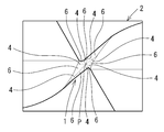
- FIG. 2 is an enlarged view of a portion corresponding to the portion where the chisel edge 11 of the tip portion 12 of the standard drill shown in FIG. 1 is formed in the tip portion 2 of the drill according to the first embodiment.
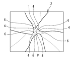
- FIG. 3 is a view when the portion is viewed with a line of sight orthogonal to the drill center line.
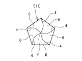
- the polygonal pyramid shape 1 is constituted by a pentagonal pyramid whose center line passing through the head vertex P coincides with the drill center line CL. Further, the polygonal pyramid shape 1 is such that the size of the bottom surface 5 (virtual bottom surface) shown in FIG. 4, in other words, the diameter D of the circle C contacting the regular pentagon formed by the bottom surface 5 is 5% of the diameter of the drill. Is set.
- the inclination angle ⁇ 1 of each side 4 extending from the head apex P with respect to the drill center line CL is set to be larger by + 15 ° than the angle ⁇ 2 which is 1 ⁇ 2 of the drill tip angle ⁇ 0. ing.
- the polygonal pyramid shape 1 can be obtained, for example, by grinding the tip 12 of a standard drill shown in FIG. 1 with a drill grinder. Further, how to arrange each side 4 of the polygonal pyramid shape 1, in other words, each pyramid surface 6 of the polygonal pyramid shape 1, around the drill center line CL can be appropriately determined according to the drill to be used. it can.
- FIG. 5 shows (a): a standard two-blade drill (hereinafter referred to as a standard drill), (b): a two-blade drill according to the first embodiment having a polygonal pyramid shape 1 (hereinafter referred to as the present invention). (Referred to as a drill), and (c): a test result of cutting resistance during processing of a standard drill with three blades (hereinafter referred to as a three-blade drill).
- a drill with a diameter of 8 mm was used, and the torque and thrust when a blind hole with a depth of 8 mm was machined using the same machining center and cutting oil were measured.
- the processing conditions of the standard drill and the drill of the present invention are a cutting speed (V) of 20 m / min and a feed (f) of 0.19 mm / rev.
- V cutting speed
- f feed
- V cutting speed
- f feed
- the drill of the present invention has a shorter torque and thrust rise at the time of machining, that is, the time from the start of machining until the measured value is stabilized, compared to the standard drill.
- the inclination angle ⁇ 1 with respect to the drill center line CL of each side 4 of the polygonal pyramid shape 1 is 1 ⁇ 2 of the tip angle ⁇ 0 of the drill, in other words, the drill center line of the cutting edge 7 It can be inferred that this is because it is formed larger than the inclination angle ⁇ 2 with respect to CL.
- the drill of the present invention stabilizes the drill more quickly because the distance from the tip of the drill (head apex P of the polygonal pyramid shape 1) to the shoulder is shorter than the standard drill. Can do.
- the drill of the present invention has a smaller torque amplitude in the entire region (period from the start of processing to the completion of processing) than the standard drill. That is, the drill of the present invention can perform smooth cutting with less torque fluctuation during processing and less vibration.
- the drill cuttings 8 of the present invention shown in FIG. 6 with the cuttings 9 of a standard drill.
- the conical shape 8a is formed with a uniform size and a constant pitch, whereas the cutting waste 9 of a standard drill has a conical shape.
- the size and pitch of the shape 9a vary.
- the drill of the present invention has a small torque fluctuation during processing even when compared with a three-blade drill.
- the number of sides 4 extending from the head vertex P of the polygonal pyramid shape 1 is an odd number (five sides in the first embodiment).
- the component force T1 (sliding force) in the direction orthogonal to the thrust of the drill acting on one side 4 of 1 is the component force T2, T3 in the direction orthogonal to the thrust of the drill acting on two sides 4 opposite to this.
- the number of sides 4 extending from the top vertex P of the polygonal pyramid shape 1 is an even number (for example, 4 sides), that is, the drill thrust acting on one side 4 of the polygonal pyramid shape 1.
- the first embodiment has the following effects.
- the chisel edge 11 of the tip 12 is abolished, and the inclination angle ⁇ 1 with respect to the drill center line CL of each side 4 extending from the head apex P is 1 / of the tip angle ⁇ 0 of the drill. Since the polygonal pyramid shape 1 formed larger than the angle ⁇ 2 of 2 is formed, the whirling of the drill caused by the chisel edge 11, that is, the so-called chisel step is eliminated, enabling stable cutting and improving the accuracy of the hole. Can be made.
- the distance (tip length) from the tip of the drill (head apex P of the polygonal pyramid shape 1) to the shoulder can be shortened, and as a result, rising, in other words, The time from the start of machining to the stabilization of the drill (cutting force) is shortened and the vibration of the drill is reduced over the entire machining area (behaves stable), so that the accuracy of the hole can be improved.
- the direction orthogonal to the thrust of the drill acting on one side 4 of the polygonal pyramid shape 1 Component force T1 (sliding force) can be received by component forces T2 and T3 (accepting force) in the direction perpendicular to the thrust of the drill acting on the two sides 4 opposite to this.
- the number of sides 4 extending from the head vertex P is an even number (for example, 4 sides), that is, the component force T1 (sliding force) in the direction perpendicular to the thrust of the drill acting on one side 4 of the polygonal pyramid shape 1
- the drill behavior (vibration, whirling, etc.) is more stable, Accuracy can be improved.
- it is possible to process with high accuracy even with an inexpensive two-blade drill it is not necessary to employ a drill with a relatively expensive number of blades of three or more in order to increase the accuracy of the hole.
- the running cost of equipment can be reduced. Furthermore, since it is not necessary to change the machining conditions (NC machine machining program), it is possible to prevent an increase in man-hours.
- the polygonal pyramid shape 1 can be formed by grinding the tip of an existing drill (standard drill) with a grinder, so that implementation is easy and cost increase can be suppressed. Furthermore, since there is little effort to readjust the regrind conditions in the drill grinder, it is possible to prevent an increase in the number of regrinding steps.
- the implementation target is a two-blade drill, but the drill to be implemented is not limited in the number of blades, and can be employed for a three-blade, four-blade drill, for example. .
- the polygonal pyramid shape 1 is a pentagonal pyramid.
- the polygonal pyramid shape 1 can be appropriately selected from, for example, a hexagonal pyramid, a heptagonal pyramid, and the like.
- FIG. 7 is a diagram corresponding to FIG. 2 when a 6-sided (hexagonal) polygonal pyramid shape 1 is adopted for a 2-blade drill
- FIG. FIG. 9 is a diagram corresponding to FIG.
- FIG. 9 is a diagram of FIG. 2 when a polygonal pyramid shape 1 of 7-sided pyramids is adopted
- FIG. 9 is a diagram of FIG. 2 when a polygonal pyramid shape 1 of 5 sides (5-pyramid) is adopted for a three-blade drill
- FIG. 10 is a diagram corresponding to FIG. 2 when a six-sided (hexagonal pyramid) polygonal pyramid shape 1 is adopted for a three-blade drill
- FIG. It is a figure corresponding to FIG. 2 at the time of employ
- each side 4 of the polygonal pyramid shape 1 is a line of sight in the drill center line CL direction (viewed on the paper in FIG. 12), and the center is the clockwise direction. It is formed by a curve that becomes convex.
- the contact length with the workpiece of each side 4 of the polygonal pyramid shape 1 at the time of machining in other words, the length of the cutting edge 7 (see FIG. 2) of the polygonal pyramid shape 1 is Since each side 4 of the polygonal pyramid shape 1 is increased in comparison with a case where the sides 4 are formed by straight lines (see FIG. 4), the load during processing is dispersed and the sharpness of the cutting edge is improved. ) Buckling.
- FIG. 14 the drill according to the third embodiment is different from the first embodiment shown in FIG. 3 in which each pyramid surface 6 of the polygonal pyramid shape 1 is a plane.
- the pyramid surface 6 is constituted by a concave curved surface.
- each pyramid surface 6 of the polygonal pyramid shape 1 being processed and the workpiece can be reduced, and the cutting temperature rise due to friction, and further, wear of the polygonal pyramid shape 1 is caused. Can be prevented.
- the concave shape is formed by forming each pyramidal surface 6 of the polygonal pyramid shape 1 with a curved surface, and as shown in FIG.
- a groove 10 having a V-shaped cross section extending radially from the point P can be formed.
- the groove 10 can be formed such that the groove width increases linearly from the top vertex P.
Landscapes
- Engineering & Computer Science (AREA)
- Mechanical Engineering (AREA)
- Drilling Tools (AREA)
- Processing Of Stones Or Stones Resemblance Materials (AREA)
Abstract
Description
以下に、本願において特許請求が可能と認識されている発明(以下、請求可能発明と称する)の態様を例示し、例示された各態様について説明する。ここでは、各態様を、特許請求の範囲と同様に、項に区分すると共に各項に番号を付し、必要に応じて他の項の記載を引用する形式で記載する。これは、請求可能発明の理解を容易にするためであり、請求可能発明を構成する構成要素の組み合わせを、以下の各項に記載されたものに限定する趣旨ではない。つまり、請求可能発明は、各項に付随する記載、実施形態の記載等を参酌して解釈されるべきであり、その解釈に従う限りにおいて、各項の態様にさらに他の構成要素を付加した態様も、また、各項の態様から構成要素を削除した態様も、請求可能発明の一態様となり得る。
なお、以下の各項において、(1)~(3)項の各々が、特許請求の範囲に記載した請求項1~3の各々に相当する。
本項に記載のドリルによれば、チゼルエッジを廃止することができる。これにより、チゼルエッジに起因するドリルの振れ回り、いわゆる、チゼル歩みが解消され、安定した切削が可能になり、穴の精度を向上させることができる。
また、多角錐形状の頭頂点から延びる各辺(以下、単に各辺という)のドリル中心線に対する傾斜角度が、ドリルの先端角の1/2の角度、言い換えると、切刃のドリル中心線に対する傾斜角度よりも大きく形成されているので、標準のドリルと比較して、ドリルの先端(本項の態様では多角錐形状の頭頂点)から肩口までの距離(先端部長さ)が短くなる。これにより、ドリルがより早く安定し、穴の精度を向上させることができる。また、相対的に安価な刃数の少ないドリル(例えば、2枚刃)であっても高い精度の加工が可能であることから、穴の精度を高めるために相対的に高価な刃数の多いドリル(例えば、3枚刃、4枚刃)を採用する必要がないので、加工品の製造コストを削減することができる。さらに、加工条件(NC装置の加工プログラム)を変更する必要がないので、工数の増大を防ぐことができる。
また、多角錐形状は、既存のドリルの先端部を研削することで形成することができるので、ドリルの製造コストの増大を抑止することができる。さらに、ドリルの研削盤における再研削の条件を再調整する手間が少ないので、再研削の工数の増加を防ぐことができる。
さらに、多角錐形状の各角錐面を凹形状に形成したので、加工中の多角錐形状の各角錐面と被加工物との摩擦を軽減することができ、摩擦による切削温度上昇、延いては、多角錐形状の摩耗を防ぐことができる。
本項の態様において、対象となるドリルに刃数の限定はなく、例えば、2枚刃、3枚刃、4枚刃のドリルに採用することができる。
また、多角錐形状は、例えば、5角錐、6角錐、7角錐等を適宜選択することができる。
また、多角錐形状の頭頂点から延びる各辺のドリル中心線に対する傾斜角度は、ドリルの先端角の1/2の角度+15°程度とすることが望ましい。例えば、ドリルの先端角が118°である場合、多角錐形状の頭頂点から延びる各辺のドリル中心線に対する傾斜角度は、74°程度に設定することが望ましい。
また、多角錐形状の底面の大きさを、多角錐形状の底面に近似する正多角形が接する円の直径と定義した場合、多角錐形状の底面の大きさは、ドリルの直径の5~6%とすることが望ましい。例えば、ドリルの直径が10 mmである場合、多角錐形状の底面の大きさは、0.5 ~0.6 mmに設定することが望ましい。
さらに、凹形状は、多角錐形状の各角錐面を曲面によって構成して形成する他、平面によって構成される各角錐面に、頭頂点から放射状に延びる断面がV字形状の溝を設けることで形成することができる。この場合、溝は、溝幅が頭頂点から直線的に増加するように形成することができる。
本項に記載のドリルによれば、加工時における多角錐形状の各辺の被加工物との接触長さ、言い換えると、多角錐形状の切刃の長さが、多角錐形状の各辺が直線によって形成される場合と比較して増加するので、負荷が分散されて切刃の切れ味が向上し、先端(多角錐形状)の座屈を抑制することができる。
本項の態様において、多角錐形状の各辺は、例えば、ドリル中心線方向の視線で中央が時計回り方向へ凸となるような曲線によって構成することができる。
本項に記載のドリルによれば、例えば、多角錐形状の頭頂点から延びる辺の数を5辺、すなわち、多角錐形状を5角錐形状とした場合、多角錐形状の1辺に作用するドリルの推力に直交する方向への分力を、これに対向する2辺によって受け止めることができる。これは、多角錐形状の1辺に作用するドリルの推力に直交する方向への分力を、面によって受け止めることに概ね等しく、多角錐形状の頭頂点から延びる辺の数が偶数(例えば、4辺)、すなわち、多角錐形状の1辺に作用するドリルの推力に直交する方向への分力を、これに対向する1辺のみによって受け止める場合と比較して、ドリルの挙動(振動、振れ回り等)がより安定し、穴の精度を向上させることができる。
本項の態様において、多角錐形状の頭頂点から延びる辺の数は、5辺の他、例えば、3辺、7辺等とすることができる。
本発明の第1実施形態を添付した図を参照して説明する。
ここでは、標準的なドリル、すなわち、図1に示されるように、先端部12の逃げ面13が円錐研削によって再研削される2枚刃のドリルのチゼルエッジ11が形成されている部分に、本発明の多角錐形状1を採用した態様を説明する。なお、第1実施形態のドリルは、図1に示される標準的なドリルに対してチゼルエッジ11が形成されている部分のみが異なり、明細書の記載を簡潔にすることを目的に、この標準的なドリルと異なる部分のみを説明する。
図5に、(a):標準の2枚刃のドリル(以下、標準のドリルという)、(b):多角錐形状1を備える第1実施形態の2枚刃のドリル(以下、本発明のドリルという)、及び(c):3枚刃の標準のドリル(以下、3枚刃のドリルという)の加工中の切削抵抗の試験結果を示す。なお、この試験では、直径8 mmのドリルで実施したものであり、同一のマシニングセンタ及び切削油を使用し、深さ8 mmの止まり穴を加工した時のトルク及びスラストを測定した。
また、標準のドリル及び本発明のドリルの加工条件は、切削速度(V)が20 m/min、送り(f)が0.19 mm/revであり、3枚刃のドリルの加工条件は、切削速度(V)が20 m/min、送り(f)が0.28 mm/revである。
第1実施形態によれば、先端部12のチゼルエッジ11を廃止して、その部分に、頭頂点Pから延びる各辺4のドリル中心線CLに対する傾斜角度θ1が、ドリルの先端角θ0の1/2の角度θ2よりも大きく形成される多角錐形状1を形成したので、チゼルエッジ11に起因するドリルの振れ回り、いわゆる、チゼル歩みが解消され、安定した切削が可能になり、穴の精度を向上させることができる。
また、標準のドリルと比較して、ドリルの先端(多角錐形状1の頭頂点P)から肩口までの距離(先端部長さ)を短くすることが可能になり、その結果、立ち上がり、言い換えると、加工開始からドリル(切削抵抗)が安定するまでの時間が短縮され、且つ加工の全域に亘ってドリルの振動が小さくなる(挙動が安定している)ので、穴の精度を向上させることができる。
また、多角錐形状1の頭頂点Pから延びる辺4の数を奇数(第1実施形態では、5辺)としたので、多角錐形状1の1辺4に作用するドリルの推力に直交する方向への分力T1(すべる力)を、これに対向する2辺4に作用するドリルの推力に直交する方向への分力T2,T3(受け止める力)よって受け止めることができ、多角錐形状1の頭頂点Pから延びる辺4の数が偶数(例えば、4辺)、すなわち、多角錐形状1の1辺4に作用するドリルの推力に直交する方向への分力T1(すべる力)を、これに対向する1辺4のみに作用するドリルの推力に直交する方向への分力(受け止める力)によって受け止める場合と比較して、ドリルの挙動(振動、振れ回り等)がより安定し、穴の精度を向上させることができる。
また、安価な2枚刃のドリルであっても高い精度の加工が可能であることから、穴の精度を高めるために比較的高価な刃数が3枚以上のドリルを採用する必要がなく、設備のランニングコストを削減することができる。さらに、加工条件(NC装置の加工プログラム)を変更する必要がないので、工数の増大を防ぐことができる。
また、多角錐形状1は、既存のドリル(標準のドリル)の先端部を研削盤によって研削することで形成することができるので、実施が容易であると共にコストアップを抑止することができる。さらに、ドリルの研削盤における再研削の条件を再調整する手間が少ないので、再研削の工数の増加を防ぐことができる。
第1実施形態では、実施の対象を2枚刃のドリルとしたが、実施の対象となるドリルに刃数の限定はなく、例えば、3枚刃、4枚刃のドリルに採用することができる。
また、第1実施形態では、多角錐形状1を5角錐としたが、多角錐形状1は、例えば、6角錐、7角錐等を適宜選択することができる。
なお、図7は、2枚刃のドリルに6辺(6角錐)の多角錐形状1を採用した場合の図2に対応する図であり、図8は、2枚刃のドリルに7辺(7角錐)の多角錐形状1を採用した場合の図2に対応する図であり、図9は、3枚刃のドリルに5辺(5角錐)の多角錐形状1を採用した場合の図2に対応する図であり、図10は、3枚刃のドリルに6辺(6角錐)の多角錐形状1を採用した場合の図2に対応する図であり、図11は、3枚刃のドリルに7辺(7角錐)の多角錐形状1を採用した場合の図2に対応する図である。
本発明の第2実施形態を添付した図に基づいて説明する。なお、第1実施形態と同一あるいは相当する構成には同一の名称および符号を付与し、重複する説明を省略する。
第2実施形態のドリルは、図12及び図13に示されるように、多角錐形状1の各辺4が、ドリル中心線CL方向の視線(図12における紙面視)で、中央が時計回り方向へ凸となるような曲線によって形成されている。
本発明の第3実施形態を添付した図に基づいて説明する。なお、第1実施形態と同一あるいは相当する構成には同一の名称および符号を付与し、重複する説明を省略する。
第3実施形態のドリルは、図14に示されるように、多角錐形状1の各角錐面6が平面によって構成される図3に示される第1実施形態に対して、多角錐形状1の各角錐面6が凹形状の曲面によって構成されている。
なお、凹形状は、多角錐形状1の各角錐面6を曲面によって構成して形成する他、図15に示されるように、平面によって構成される各角錐面6(図3参照)に、頭頂点Pから放射状に延びる断面がV字形状の溝10を設けることで形成することができる。この場合、溝10は、その溝幅が頭頂点Pから直線的に増加するように形成することができる。
Claims (3)
- ドリルの先端部に、頭頂点がドリル中心線上に位置し、前記頭頂点から延びる各辺の前記ドリル中心線に対する傾斜角度がドリルの先端角の1/2の角度よりも大きい多角錐形状が設けられ、
前記多角錐形状の各角錐面は、凹形状に形成されることを特徴とするドリル。 - 前記多角錐形状の各辺は、曲線によって形成されることを特徴とする請求項1に記載のドリル。
- 前記多角錐形状の前記頭頂点から延びる辺の数は、奇数であることを特徴とする請求項1又は2に記載のドリル。
Priority Applications (5)
| Application Number | Priority Date | Filing Date | Title |
|---|---|---|---|
| JP2012551036A JP5708944B2 (ja) | 2010-12-28 | 2011-12-28 | ドリル |
| EP11854507.8A EP2659998B1 (en) | 2010-12-28 | 2011-12-28 | Two-blade drill |
| BR112013016494-8A BR112013016494B1 (pt) | 2010-12-28 | 2011-12-28 | Broca de duas laminas |
| CN201180062767.1A CN103282148B (zh) | 2010-12-28 | 2011-12-28 | 钻头 |
| US13/996,929 US9238272B2 (en) | 2010-12-28 | 2011-12-28 | Drill |
Applications Claiming Priority (2)
| Application Number | Priority Date | Filing Date | Title |
|---|---|---|---|
| JP2010-292004 | 2010-12-28 | ||
| JP2010292004 | 2010-12-28 |
Publications (1)
| Publication Number | Publication Date |
|---|---|
| WO2012091085A1 true WO2012091085A1 (ja) | 2012-07-05 |
Family
ID=46383173
Family Applications (1)
| Application Number | Title | Priority Date | Filing Date |
|---|---|---|---|
| PCT/JP2011/080374 Ceased WO2012091085A1 (ja) | 2010-12-28 | 2011-12-28 | ドリル |
Country Status (6)
| Country | Link |
|---|---|
| US (1) | US9238272B2 (ja) |
| EP (1) | EP2659998B1 (ja) |
| JP (1) | JP5708944B2 (ja) |
| CN (1) | CN103282148B (ja) |
| BR (1) | BR112013016494B1 (ja) |
| WO (1) | WO2012091085A1 (ja) |
Families Citing this family (1)
| Publication number | Priority date | Publication date | Assignee | Title |
|---|---|---|---|---|
| JP7071971B2 (ja) * | 2016-10-07 | 2022-05-19 | マパル ファブリック フュール プラツィジョンズベルクゼウグ ドクトル.クレス カーゲー | 金属穴開け工具 |
Citations (5)
| Publication number | Priority date | Publication date | Assignee | Title |
|---|---|---|---|---|
| JP2002126925A (ja) * | 2000-10-25 | 2002-05-08 | Mmc Kobelco Tool Kk | ツイストドリル |
| JP2002200510A (ja) | 2000-12-27 | 2002-07-16 | Tsutomu Fuma | ドリル |
| JP2003326410A (ja) * | 2002-02-27 | 2003-11-18 | Mitsubishi Materials Kobe Tools Corp | センタドリル |
| JP2004025383A (ja) * | 2002-06-27 | 2004-01-29 | Dijet Ind Co Ltd | ドリル |
| JP2007301706A (ja) * | 2006-05-15 | 2007-11-22 | Osg Corp | ドリル |
Family Cites Families (23)
| Publication number | Priority date | Publication date | Assignee | Title |
|---|---|---|---|---|
| US2715772A (en) * | 1950-07-15 | 1955-08-23 | Frico G M B H | Dental burr |
| JPS5390291U (ja) | 1976-12-24 | 1978-07-24 | ||
| US4565471A (en) * | 1979-10-02 | 1986-01-21 | Mitsubishi Kinzoku Kabushiki Kaisha | Drill bit |
| DE3233968A1 (de) * | 1982-09-14 | 1984-03-15 | Hartmetallwerkzeugfabrik Andreas Maier GmbH + Co KG, 7959 Schwendi | Mehrlippenbohrer |
| JPS6168811U (ja) | 1984-10-12 | 1986-05-12 | ||
| JPH0569214A (ja) | 1991-06-04 | 1993-03-23 | Mitsubishi Materials Corp | 穴あけ工具 |
| JPH0596414A (ja) | 1991-10-03 | 1993-04-20 | O S G Kk | チゼルなし円錐面渦巻き刃ドリル |
| JP2981055B2 (ja) * | 1992-04-28 | 1999-11-22 | 富士精工株式会社 | バニシングドリル |
| US5236291A (en) * | 1992-08-31 | 1993-08-17 | General Motors Corporation | Multi-tooth drill with improved chisel edge |
| JP2602032Y2 (ja) * | 1993-04-06 | 1999-12-20 | 富士重工業株式会社 | ダブルアングルドリル |
| US5664914A (en) * | 1994-04-27 | 1997-09-09 | Kabushiki Kaisha Mekuto | Drill |
| US6257889B1 (en) * | 1999-03-25 | 2001-07-10 | Temple University - Of The Commonwealth System Of Higher Education | Dental bur and method |
| US7097396B1 (en) * | 2000-02-16 | 2006-08-29 | Kabushiki Kaisha Miyanaga | Drill bit |
| US6929433B2 (en) * | 2000-10-12 | 2005-08-16 | Randall C. Andronica | Drill and surface insensitive starting drill for difficult materials and deep holes |
| JP2003334710A (ja) | 2002-05-15 | 2003-11-25 | Union Tool Co | ドリル |
| US7832966B2 (en) * | 2003-01-30 | 2010-11-16 | Kennametal Inc. | Drill for making flat bottom hole |
| JP2007185719A (ja) | 2006-01-11 | 2007-07-26 | Yamamura System Giken:Kk | 下穴加工用の切れ刃を備えたドリル |
| DE102008004564B4 (de) * | 2008-01-15 | 2013-04-11 | EMUGE-Werk Richard Glimpel GmbH & Co. KG Fabrik für Präzisionswerkzeuge | Bohrwerkzeug mit Ausspitzung |
| SE532432C2 (sv) * | 2008-05-09 | 2010-01-19 | Sandvik Intellectual Property | Borrkropp med primära och sekundära släppningsytor |
| JP2010036295A (ja) * | 2008-08-05 | 2010-02-18 | Osg Corp | ドリル及びドリルの製造方法 |
| US8226654B2 (en) * | 2008-12-04 | 2012-07-24 | Aeton Medical Llc | Trocar-tipped drill bit |
| WO2010086988A1 (ja) * | 2009-01-29 | 2010-08-05 | オーエスジー株式会社 | ダブルアングルドリル |
| DE102009003287A1 (de) * | 2009-05-20 | 2010-11-25 | Hilti Aktiengesellschaft | Bohrer |
-
2011
- 2011-12-28 BR BR112013016494-8A patent/BR112013016494B1/pt not_active IP Right Cessation
- 2011-12-28 CN CN201180062767.1A patent/CN103282148B/zh active Active
- 2011-12-28 JP JP2012551036A patent/JP5708944B2/ja active Active
- 2011-12-28 WO PCT/JP2011/080374 patent/WO2012091085A1/ja not_active Ceased
- 2011-12-28 EP EP11854507.8A patent/EP2659998B1/en active Active
- 2011-12-28 US US13/996,929 patent/US9238272B2/en active Active
Patent Citations (5)
| Publication number | Priority date | Publication date | Assignee | Title |
|---|---|---|---|---|
| JP2002126925A (ja) * | 2000-10-25 | 2002-05-08 | Mmc Kobelco Tool Kk | ツイストドリル |
| JP2002200510A (ja) | 2000-12-27 | 2002-07-16 | Tsutomu Fuma | ドリル |
| JP2003326410A (ja) * | 2002-02-27 | 2003-11-18 | Mitsubishi Materials Kobe Tools Corp | センタドリル |
| JP2004025383A (ja) * | 2002-06-27 | 2004-01-29 | Dijet Ind Co Ltd | ドリル |
| JP2007301706A (ja) * | 2006-05-15 | 2007-11-22 | Osg Corp | ドリル |
Also Published As
| Publication number | Publication date |
|---|---|
| EP2659998B1 (en) | 2020-01-22 |
| US20140003877A1 (en) | 2014-01-02 |
| CN103282148A (zh) | 2013-09-04 |
| EP2659998A1 (en) | 2013-11-06 |
| BR112013016494B1 (pt) | 2020-11-17 |
| BR112013016494A2 (pt) | 2016-09-27 |
| EP2659998A4 (en) | 2016-12-28 |
| US9238272B2 (en) | 2016-01-19 |
| CN103282148B (zh) | 2016-08-10 |
| JPWO2012091085A1 (ja) | 2014-06-05 |
| JP5708944B2 (ja) | 2015-04-30 |
Similar Documents
| Publication | Publication Date | Title |
|---|---|---|
| JP5869691B2 (ja) | ボールエンドミル | |
| KR101236094B1 (ko) | 스로어웨이식 절삭 회전 공구 | |
| CA2608291C (en) | High helix/low lead cutting tool | |
| JP6384385B2 (ja) | ラフィングエンドミル | |
| KR20110036606A (ko) | 스로어웨이식 절삭 회전 공구 | |
| JP2012000720A (ja) | 総形カッターの製造方法および総形カッターの研削工具 | |
| KR102296651B1 (ko) | 기계 가공하기 위한 적층 재료 공구 및 방법 | |
| JP5946984B1 (ja) | 溝部の加工方法 | |
| CN110730700B (zh) | 铣削方法和切削刀片的用途 | |
| JP4753893B2 (ja) | ダイヤモンドリーマ | |
| JP6918013B2 (ja) | 切削工具および切削加工方法 | |
| JP5708944B2 (ja) | ドリル | |
| JP3111276U (ja) | 面取りエンドミル | |
| JP5645333B2 (ja) | クリスマスカッタ | |
| JP4992460B2 (ja) | エンドミル | |
| JP5492357B2 (ja) | クリスマスカッタ | |
| JP2016155178A (ja) | 回転工具、及び回転工具の製造方法 | |
| KR101851528B1 (ko) | 플랫 드릴 | |
| JP2008044040A (ja) | 回転切削工具 | |
| WO2010061478A1 (ja) | スローアウェイ式切削回転工具 | |
| JP2012011505A (ja) | 翼溝加工用クリスマスカッタ | |
| Levyc’kyy | Staggered Tooth Cut-off Milling Cutter for Structural Materials’ Machining | |
| JP2015182192A (ja) | ラフィングエンドミル | |
| JP2016074076A (ja) | 工具 |
Legal Events
| Date | Code | Title | Description |
|---|---|---|---|
| 121 | Ep: the epo has been informed by wipo that ep was designated in this application |
Ref document number: 11854507 Country of ref document: EP Kind code of ref document: A1 |
|
| ENP | Entry into the national phase |
Ref document number: 2012551036 Country of ref document: JP Kind code of ref document: A |
|
| WWE | Wipo information: entry into national phase |
Ref document number: 2011854507 Country of ref document: EP |
|
| NENP | Non-entry into the national phase |
Ref country code: DE |
|
| WWE | Wipo information: entry into national phase |
Ref document number: 13996929 Country of ref document: US |
|
| REG | Reference to national code |
Ref country code: BR Ref legal event code: B01A Ref document number: 112013016494 Country of ref document: BR |
|
| ENP | Entry into the national phase |
Ref document number: 112013016494 Country of ref document: BR Kind code of ref document: A2 Effective date: 20130626 |