WO2012093700A1 - 原子炉 - Google Patents
原子炉 Download PDFInfo
- Publication number
- WO2012093700A1 WO2012093700A1 PCT/JP2012/050112 JP2012050112W WO2012093700A1 WO 2012093700 A1 WO2012093700 A1 WO 2012093700A1 JP 2012050112 W JP2012050112 W JP 2012050112W WO 2012093700 A1 WO2012093700 A1 WO 2012093700A1
- Authority
- WO
- WIPO (PCT)
- Prior art keywords
- core
- fuel
- combustion
- fuel assembly
- nuclear reactor
- Prior art date
- Legal status (The legal status is an assumption and is not a legal conclusion. Google has not performed a legal analysis and makes no representation as to the accuracy of the status listed.)
- Ceased
Links
Images



Classifications
-
- G—PHYSICS
- G21—NUCLEAR PHYSICS; NUCLEAR ENGINEERING
- G21C—NUCLEAR REACTORS
- G21C7/00—Control of nuclear reaction
- G21C7/30—Control of nuclear reaction by displacement of the reactor fuel or fuel elements
-
- G—PHYSICS
- G21—NUCLEAR PHYSICS; NUCLEAR ENGINEERING
- G21C—NUCLEAR REACTORS
- G21C1/00—Reactor types
- G21C1/02—Fast fission reactors, i.e. reactors not using a moderator ; Metal cooled reactors; Fast breeders
-
- G—PHYSICS
- G21—NUCLEAR PHYSICS; NUCLEAR ENGINEERING
- G21C—NUCLEAR REACTORS
- G21C5/00—Moderator or core structure; Selection of materials for use as moderator
- G21C5/18—Moderator or core structure; Selection of materials for use as moderator characterised by the provision of more than one active zone
-
- G—PHYSICS
- G21—NUCLEAR PHYSICS; NUCLEAR ENGINEERING
- G21C—NUCLEAR REACTORS
- G21C3/00—Reactor fuel elements and their assemblies; Selection of substances for use as reactor fuel elements
-
- G—PHYSICS
- G21—NUCLEAR PHYSICS; NUCLEAR ENGINEERING
- G21C—NUCLEAR REACTORS
- G21C3/00—Reactor fuel elements and their assemblies; Selection of substances for use as reactor fuel elements
- G21C3/30—Assemblies of a number of fuel elements in the form of a rigid unit
- G21C3/32—Bundles of parallel pin-, rod-, or tube-shaped fuel elements
- G21C3/326—Bundles of parallel pin-, rod-, or tube-shaped fuel elements comprising fuel elements of different composition; comprising, in addition to the fuel elements, other pin-, rod-, or tube-shaped elements, e.g. control rods, grid support rods, fertile rods, poison rods or dummy rods
- G21C3/3262—Enrichment distribution in zones
-
- Y—GENERAL TAGGING OF NEW TECHNOLOGICAL DEVELOPMENTS; GENERAL TAGGING OF CROSS-SECTIONAL TECHNOLOGIES SPANNING OVER SEVERAL SECTIONS OF THE IPC; TECHNICAL SUBJECTS COVERED BY FORMER USPC CROSS-REFERENCE ART COLLECTIONS [XRACs] AND DIGESTS
- Y02—TECHNOLOGIES OR APPLICATIONS FOR MITIGATION OR ADAPTATION AGAINST CLIMATE CHANGE
- Y02E—REDUCTION OF GREENHOUSE GAS [GHG] EMISSIONS, RELATED TO ENERGY GENERATION, TRANSMISSION OR DISTRIBUTION
- Y02E30/00—Energy generation of nuclear origin
- Y02E30/30—Nuclear fission reactors
Definitions
- the present invention relates to a nuclear reactor.
- Nuclear reactors are used for power generation facilities.
- the nuclear reactor includes a fast neutron reactor.
- a fast neutron reactor is a nuclear reactor that generates power by fissioning fissionable nuclides mainly with fast neutrons, and the core is cooled by heavy metals such as sodium and lead bismuth alloys, or gas. In conventional nuclear reactors, fission occurs and power is generated throughout the core.
- the criticality of the core of the nuclear reactor and the adjustment of the power are performed by, for example, control rods.
- the control rod is made of a material that easily absorbs neutrons.
- a control rod is inserted into the core, and as the combustion proceeds, the control rod is gradually pulled out to maintain the critical state while maintaining the output.
- control for maintaining the criticality of the nuclear reactor is necessary. Control for maintaining criticality is performed continuously from the early stage of the combustion cycle to the end of the combustion cycle.
- Japanese Patent No. 3463100 discloses a nuclear reactor that does not require control for maintaining criticality in a combustion cycle.
- This nuclear reactor adopts a combustion method called CANDLE (Constant Axial Shape of Neutron Flux, Nuclide Densities and Power Shape Shape, and Life Life of Energy Production).
- CANDLE Constant Axial Shape of Neutron Flux, Nuclide Densities and Power Shape Shape, and Life Life of Energy Production.
- the core can be roughly divided into a new fuel part, a combustion part, and a part where combustion has progressed.
- the combustion section moves toward the new fuel section at a speed proportional to the output with combustion.
- CANDLE combustion after one combustion cycle is completed, the fuel is changed to perform the next combustion cycle.
- the fuel is exchanged, the fuel which has been burned in the direction of the core axis can be taken out, and new fuel can be loaded on the end opposite to the taken-out end.
- the reactor core characteristics can be made almost constant even when combustion progresses, operation control is simplified, and a nuclear reactor with a low probability of accidents. Can be provided. Further, since there is no need to arrange the control rod in the core, there is no possibility of an accident that the control rod is accidentally pulled out during the operation period. In addition, the amount of waste can be reduced because of the high burnup when fuel is taken out.
- operation can be performed using only natural uranium or degraded uranium as a new fuel after the second cycle. Since these fuels are subcritical, they can be easily transported and stored. Moreover, since about 40% of uranium can be used as energy without enrichment or reprocessing, resources can be used effectively. In addition, the new fuel after the second cycle has characteristics such as high proliferation resistance because it does not require enrichment or reprocessing.
- the starting and stopping of the nuclear reactor in the prior art are performed by using control rods.
- the output of the nuclear reactor can be reduced and stopped.
- the output of the core can be increased after the core is made critical by pulling out the inserted control rod.
- the reactor can be started and stopped by arranging control rods to be inserted into the core.
- criticality could be achieved by increasing the concentration of fissile uranium or plutonium or increasing the number of fuel assemblies of new fuel.
- enriched uranium or the like can be included in the new fuel, but it is preferable to use only natural uranium or degraded uranium as the new fuel without using enriched uranium or the like.
- the power distribution in the radial direction is substantially constant.
- a space in which no fuel is loaded is formed in the core. In this space, there is a problem that the output density becomes small and the radial output distribution becomes non-uniform.
- An object of the present invention is to provide a nuclear reactor that includes a core in which a combustion section moves toward a new fuel section as fuel is burned, and that can be started and stopped without a control rod.
- the nuclear reactor according to the present invention includes a new fuel part loaded with a new fuel, and a combustion part disposed on one side of the new fuel part and generating neutrons to burn the fuel.
- the new fuel is natural uranium.
- at least one of depleted uranium is included, and plutonium generated by uranium absorbing neutrons generates fission, generating output, and from the beginning to the end of the combustion cycle, the combustion section heads toward the new fuel section
- the plurality of fuel assemblies include a fuel assembly fixed to the core and a fuel assembly movable in the axial direction of the core. The reactor is stopped by pulling out the movable fuel assembly from the core, and the reactor is started by inserting the movable fuel assembly into the core from the state of being pulled out.
- an auxiliary member including an absorbing material having a function of absorbing neutrons is provided, and the auxiliary member is connected to a movable fuel assembly.
- the movable fuel is provided. It is preferable that the assembly is pulled out from the core and the auxiliary member is inserted into the core.
- the movable fuel assembly is preferably formed so that the entire fuel assembly is pulled out from the core.
- the core is divided into a central region and a peripheral region, the movable fuel assembly is disposed in the central region, and the fuel assembly fixed to the core is disposed in the peripheral region. be able to.
- the movable fuel assemblies can be discretely arranged in the core at predetermined intervals.
- a nuclear reactor that includes a core in which a combustion section moves toward a new fuel section as fuel is burned, and that can be started and stopped without a control rod.
- FIG. 1 is a schematic diagram of a nuclear reactor in an embodiment. It is a schematic plan view of the core in an embodiment. It is a schematic sectional drawing of the part containing the core in embodiment. It is a schematic perspective view of the fuel assembly in an embodiment. It is a schematic perspective view of the fuel rod in an embodiment. It is a schematic perspective view of the fuel assembly and the auxiliary member in the embodiment. It is the schematic explaining the combustion state of the fuel of the core in embodiment. It is a graph explaining the change of an infinite neutron multiplication factor with respect to the neutron fluence of the fuel in embodiment. It is a graph explaining the relationship between a core height and an infinite neutron multiplication factor of fuel. It is a figure explaining the change of the power density of the core and fuel replacement
- the reactor in the embodiment will be described with reference to FIGS.
- the nuclear reactor in the present embodiment is a fast neutron reactor that generates plutonium fission mainly by fast neutrons.
- the nuclear reactor in the present embodiment is arranged in a power generation facility, and generates power using the heat of the coolant flowing out from the nuclear reactor.
- FIG. 1 is a schematic diagram of a nuclear reactor in the present embodiment.
- the power generation facility in the present embodiment includes a nuclear reactor 1.
- the nuclear reactor 1 includes a nuclear reactor vessel 9.
- the nuclear reactor 1 includes a core 10 disposed inside a nuclear reactor vessel 9.
- a coolant flows in the reactor vessel 9.
- no reflector is disposed around the core 10 in the present embodiment, the present invention is not limited to this configuration, and a reflector may be disposed around the core 10.
- the coolant flows into the reactor vessel 9 and passes through the inside of the core 10 as indicated by an arrow 112.
- the heat of the core 10 is transmitted to the coolant.
- the coolant flows from the lower side of the core 10 toward the upper side.
- the coolant that has flowed out of the core 10 flows out of the reactor vessel 9 as indicated by an arrow 111.
- the coolant a material having a small neutron moderating ability and neutron absorption ability can be used.
- a lead-bismuth coolant is used.
- the coolant has a function of a reflector.
- sodium can be used in addition to the lead-based coolant (liquid metal).
- a gas coolant such as helium can be used.
- lead-bismuth lead alone or isotope-separated lead 208 can be employed as the lead-based coolant.
- FIG. 2 shows a schematic plan view of the reactor core in the present embodiment.
- FIG. 3 shows a schematic cross-sectional view of the reactor core in the present embodiment. 3 is a cross-sectional view taken along the line AA in FIG. FIG. 3 shows the state during the period of power operation of the nuclear reactor.
- the core 10 in the present embodiment has a substantially hexagonal planar shape.
- the core of the nuclear reactor is not limited to this form, and can be formed in an arbitrary shape or a circle that is substantially circular when viewed in plan.
- the core 10 in the present embodiment is partitioned into a central region and a peripheral region when viewed in plan.
- Core 10 in the present embodiment includes a plurality of fuel assemblies.
- fuel assemblies are regularly arranged.
- a fuel assembly 21a as a first fuel assembly is disposed in the peripheral region of the core.
- a fuel assembly 21b as a second fuel assembly is disposed in the central region of the core.
- the fuel assembly 21a and the fuel assembly 21b are loaded with the same new fuel. In this embodiment, depleted uranium is loaded. Further, the fuel assembly 21a and the fuel assembly 21b have substantially the same structure for supporting the fuel. The fuel assembly 21a and the fuel assembly 21b in the present embodiment are formed so as to have the same height. The fuel assembly 21 a disposed in the peripheral region is fixed to the core 10. On the other hand, the fuel assembly 21b disposed in the central region is formed to be movable in the axial direction of the core as will be described later. In the core in the present embodiment, the vertical direction corresponds to the axial direction of the core.
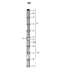
- FIG. 4 shows a schematic perspective view of the fuel assembly in the present embodiment.
- the fuel assembly 21a as the first fuel assembly will be described, but the fuel assembly 21b as the second fuel assembly has the same structure as the fuel assembly 21a.
- the fuel assembly 21a includes a plurality of fuel rods 22a.
- the end of the fuel rod 22a in the longitudinal direction is supported by the nozzle 27.
- the fuel rod 22a is supported by a plurality of support grids 25.
- the nozzle 27 and the support grid 25 support the fuel rods 22a apart from each other. In this embodiment, the distance between the fuel rods is maintained by the support grid.
- the present invention is not limited to this configuration, and a wire spacer or the like can be used instead of the support grid.
- the coolant flows between the fuel rods 22a to cool the fuel rods 22a.
- FIG. 5 shows a schematic perspective view of the fuel rod in the present embodiment.
- FIG. 5 shows a fuel rod in which the combustion of fuel moves from the upper side to the lower side.
- a part of the covering material is shown broken.
- Fuel rod 22a in the present embodiment includes a covering material 23a.
- the covering material 23a is formed in a cylindrical shape.
- the covering material 23a is made of, for example, stainless steel.
- the fuel rod 22a includes fuel pellets 24aa, 24ab, and 24ac.
- the fuel pellets 24aa, 24ab, 24ac are arranged inside the covering material 23a.
- the fuel rod 22 a is sealed with a stopper 29.
- the fuel pellets 24aa, 24ab, and 24ac are pressed by the coil spring 28.
- the fuel rod shown in FIG. 5 shows the initial state of the combustion cycle.
- the plurality of fuel pellets 24aa, 24ab, 24ac are arranged in the order of a fuel pellet 24aa containing new fuel, a fuel pellet 24ab in the middle of combustion, and a fuel pellet 24ac in which combustion has sufficiently progressed.
- the portion of the fuel pellet 24aa containing the new fuel defines the new fuel portion of the core.
- the combustion part of the core is defined by the part of the fuel pellet 24ab in the middle of combustion.
- the portion of the fuel pellet 24ac where combustion has progressed defines the portion where the combustion of the core has progressed.
- fuel pellets 24aa, 24ab, and 24ac having different burnups are arranged on the fuel rod 22a in the present embodiment.
- the covering material 23a is peeled off, and the fuel pellets in the portion where the combustion has progressed are separated from other fuel pellets.
- fuel rods for the next combustion cycle can be formed by arranging fuel pellets containing new fuel, recovered fuel pellets, and the like inside the new coating material.
- the covering material 23a may be peeled off after cutting the fuel rods for each portion. Also by this method, the fuel pellets arranged in the combustion part and the part where the combustion has progressed can be recovered.
- the fuel pellets arranged in the new fuel portion of fuel assembly 21a and fuel assembly 21b in the present embodiment include depleted uranium.
- the fuel in the present embodiment is a metal fuel, but is not limited to this form, and for example, a nitride fuel or the like can be used.
- the nuclear reactor in the present embodiment includes an auxiliary member 51 for absorbing neutrons.
- the auxiliary member 51 in the present embodiment includes an absorbing material having a function of absorbing neutrons.
- the absorbing substance a substance having a high fast neutron absorption capability is preferable.
- the absorbing material include boron carbide (B 4 C).
- FIG. 6 shows a schematic perspective view of the movable fuel assembly and auxiliary member in the present embodiment.
- the auxiliary member 51 in the present embodiment has the same configuration as that of the fuel assemblies 21a and 21b except that an absorbing material having a function of absorbing neutrons is disposed without the fuel being disposed inside the covering material.
- the auxiliary member 51 includes a plurality of absorption rods 52.
- the absorbing rod 52 has a covering material, and an absorbing substance is disposed inside the covering material.
- the auxiliary member 51 has a support grid 25 and a nozzle 27 for supporting the absorption rod 52. These support grids 25 and nozzles 27 may be the same as those used for the fuel assemblies 21a and 21b.
- the auxiliary member 51 is connected to the fuel assembly 21b.
- the fuel assembly 21b includes a plurality of fuel rods 22b.
- the fuel assembly 21 b is connected to the auxiliary member 51 via the connecting member 61.
- the fuel assembly 21b is connected to the auxiliary member 51 in series in the axial direction of the core.
- the nuclear reactor in the present embodiment includes a moving device for moving fuel assembly 21b.
- the moving device includes a driving device 71 for moving the fuel assembly 21b.
- the auxiliary member 51 is connected to the drive rod 72 via the connecting member 62.
- the drive rod 72 moves in the axial direction of the core 10 as indicated by an arrow 123.
- the auxiliary member 51 and the fuel assembly 21b can be moved in the axial direction of the core.
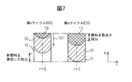
- FIG. 7 shows a schematic diagram for explaining the progress of the combustion of the core in the present embodiment.
- FIG. 7 is a schematic cross-sectional view when the core is cut along the axial direction.
- FIG. 7 shows an initial (BOC) core of the nth cycle after a plurality of combustion cycles and an end of the nth cycle (EOC) core. Also shown is a core that has been operated for multiple cycles with the same cycle length and the same fuel replacement method.
- the axis where the radial position r is zero is the core axis.
- the combustion section 12 moves toward the new fuel section 11 from the beginning to the end of the combustion cycle. That is, the core in the present embodiment performs CANDLE combustion.
- the moving speed of the combustion unit 12 is roughly proportional to the power density and inversely proportional to the fuel atom number density.
- the power density of the core in the present embodiment is high at the center of the core. At the outer periphery of the core, neutron leakage increases, so the power density decreases toward the outside in the radial direction. For this reason, the position of the combustion part in the axial direction is arranged at a position that is delayed toward the outside in the radial direction.
- the core 10 in the present embodiment includes a new fuel part 11, a combustion part 12, and a part 13 where combustion has progressed.
- the new fuel portion 11 is a portion where new fuel is disposed.
- the combustion part 12 is a part where neutrons are spontaneously generated and fuel combustion occurs. In the combustion part 12, the output is actually generated by the occurrence of fission.
- the portion 13 where combustion has progressed is a portion where combustion has progressed and almost no output is generated.
- the new fuel part 11 is arranged at the lower part of the core 10.
- the combustion unit 12 is disposed on the upper side of the new fuel unit 11. In the combustion section 12, fuel that has already started combustion in the previous cycle is arranged.
- the combustion section 12 arranged at the beginning of the cycle is a part for starting combustion. Combustion of fuel is started from the combustion unit 12, and combustion proceeds in a direction toward the new fuel unit 11 as indicated by an arrow 101. When the combustion in the n-th cycle proceeds and the end of the cycle is reached, the combustion unit 12 proceeds to the lower end of the core 10. In the present embodiment, the combustion is continued until the new fuel part 11 is almost exhausted. At the end of the combustion cycle, the new fuel portion 11 may remain.
- FIG. 8 is a graph illustrating the relationship between the neutron fluence of the fuel and the infinite neutron multiplication factor in the present embodiment.
- the horizontal axis represents the neutron fluence obtained by integrating the neutron flux with time, and the vertical axis represents the infinite neutron multiplication factor kinf.
- the neutron fluence is an amount corresponding to the burnup of the fuel, for example.
- deteriorated uranium is used as fuel.
- Depleted uranium includes, for example, about 99.8% uranium 238 and about 0.2% uranium 235.
- Uranium 238 transmutates as shown in the following equation 1 by absorbing neutrons. Uranium 238 is converted to plutonium 239.
- uranium 238 absorbs neutrons to generate plutonium 239, thereby increasing the infinite neutron multiplication factor.
- the ratio of the abundance of plutonium 239 and the like to the abundance of uranium 238 approaches a constant value, and fission products (FP) accumulate, and the infinite neutron multiplication factor gradually decreases.
- the fuel in the present embodiment has a characteristic that the infinite neutron multiplication factor increases at the initial stage of combustion, and then the infinite neutron multiplication factor gradually decreases.
- the size of the core is selected so as to satisfy such conditions, and the fuel assemblies and fuel rods are designed.
- CANDLE combustion can be carried out by adopting the core configuration as described above. That is, it is possible to form a core in which power is generated over the entire radial direction of the core and a combustion part is generated in a partial region in the axial direction of the core.
- Fig. 9 shows a graph of the infinite neutron multiplication factor when burning at an infinite core height.
- the horizontal axis represents the core height
- the vertical axis represents the infinite neutron multiplication factor of the fuel.
- the combustion section moves toward the new fuel section.
- the combustion part includes a region where the infinite neutron multiplication factor exceeds 1.
- the actual reactor core height is finite, and in this case, the infinite neutron multiplication factor at the end of the reactor core may slightly deviate from the graph shown in FIG.
- FIG. 10 shows a graph for explaining the state in which the combustion of the core proceeds and fuel replacement in the present embodiment.
- FIG. 10 shows an initial and final graph of the nth cycle core and an initial and final graph of the (n + 1) th cycle core. In each graph, the power density at the core axis, the number density of uranium 238, and the number density of fission products are shown.
- the maximum point of the power density moves toward the lower part of the core where the new fuel part 11 is arranged, as indicated by an arrow 101.
- Combustion in the present embodiment moves in a direction from the upper end to the lower end of the core.
- the speed at which the combustion section moves that is, the speed at which the maximum point of the power density moves is, for example, several centimeters per year.
- the combustion part moves slowly.
- the number density of uranium 238 becomes smaller on the downstream side of the combustion section by transmutation.
- the number density of fission products increases on the downstream side of the combustion section due to the occurrence of fission.
- the combustion ends when the combustion part reaches almost the lower end of the core.
- the combustion part arranged at the lower part of the core in the nth cycle is arranged at the upper part of the core and used as a part for starting combustion.
- a new new fuel part 11 is disposed at the lower part of the core.
- the fuel assembly 21 b is disposed inside the core 10 during the normal output operation.
- the auxiliary device 51 and the fuel assembly 21b are integrally moved as shown by the arrow 121 by driving the driving device 71.
- the fuel assembly 21b moves from the inside of the core 10 to the outside.
- the auxiliary member 51 is inserted into the core 10. That is, the movable fuel assembly 21 b is pulled out from the core 10 and the auxiliary member 51 is inserted into the core 10.
- FIG. 11 shows a schematic cross-sectional view of the core portion when the reactor is stopped in the core of the present embodiment.
- the entire movable fuel assembly 21b is pulled out from the core 10.
- An auxiliary member 51 is inserted into the core.
- the core 10 in the present embodiment maintains the criticality due to the occurrence of chained fission in the combustion portion 12.
- a part of the combustion part 12 is displaced in the axial direction of the core 10, and the fission chain in the combustion part 12 is suppressed. For this reason, the core 10 can be made subcritical.
- the auxiliary member 51 is inserted into the core 10 when the nuclear reactor is stopped.
- the auxiliary member 51 By inserting the auxiliary member 51 into the core, neutrons are absorbed by the auxiliary member 51. For this reason, the nuclear reactor can be stopped more reliably.
- the entire movable fuel assembly is formed so as to be extracted from the core.
- the nuclear reactor can be stopped more reliably.
- the extraction amount of the movable fuel is not limited to this form.
- a part of the fuel assembly is removed from the core. It may be formed so as to be pulled out.
- FIG. 12 is a schematic cross-sectional view of the core portion in the middle of starting up the nuclear reactor in the nuclear reactor according to the present embodiment. As described above, when the n-th cycle is completed, the fuel in the portion 13 where the combustion has progressed is taken out of each fuel assembly 21a, 21b, and new fuel is loaded into the new fuel portion 11.
- the fuel assembly 21b When the fuel assembly 21b is inserted into the core 10, if the fuel assembly 21b is moved at a high speed, a large positive reactivity may be applied to the core 10 and the output may increase rapidly. For this reason, when inserting the fuel assembly 21b into the core 10, it is preferable to move the fuel assembly 21b at a low speed. Alternatively, it is preferable to gradually insert the fuel assembly 21b. For example, it is preferable to gradually insert the fuel assembly 21b into the core 10 so that the output of the core reaches a predetermined ascent rate.
- the reactor core in the present embodiment can start and stop the reactor without using control rods.
- a flow path for inserting the control rod into the core 10 is unnecessary, and leakage of neutrons can be suppressed.
- the criticality of the core by CANDLE combustion can be easily achieved.
- the average power density of the core can be increased.
- the value obtained by integrating the power density in the axial direction of the core near the flow path becomes small.
- a value obtained by integrating the power density in the axial direction of the core at an arbitrary position in the radial direction is referred to as an axial integration output. Since the fuel is not loaded in the flow path for inserting the control rod, the axial integration output becomes small. For this reason, the burnup of the fuel arranged in the vicinity of the flow path into which the control rod is inserted becomes small. Fuel combustion becomes uneven in the radial direction of the core.
- the axial integration output can be made almost constant in the radial direction. That is, the radial output distribution can be made nearly constant. Fuel can be burned more uniformly.
- the radial power distribution can be made almost constant, for example, operation control is facilitated and the design of the reactor is facilitated.
- the core of the present embodiment includes a movable fuel assembly and an auxiliary member, and is formed so that the fuel assembly is pulled out from the core and the auxiliary member is inserted into the core.
- the auxiliary member may not be disposed as long as the nuclear reactor can be stopped and started by pulling out or inserting the movable fuel assembly. For example, by extracting some fuel assemblies from the core, neutron leakage from the core can be increased and the amount of uranium disposed in the core can be reduced. For this reason, a large negative reactivity can be applied to the reactor core, and depending on the structure of the nuclear reactor, the nuclear reactor can be stopped and started without an auxiliary member.
- the auxiliary member in the present embodiment includes an absorbing material having a function of absorbing neutrons, but is not limited to this form, and if the nuclear reactor can be stopped, the absorbing material is not included. It doesn't matter. Even if the absorbent material is not disposed, the mechanical strength of the core can be maintained by inserting the auxiliary member into the core.
- the movable fuel assemblies are arranged in the central region, and the fuel assemblies fixed to the core are arranged in the peripheral region. With this configuration, the configuration of the moving device that moves the fuel assembly can be simplified.
- Such a core is suitable for a small core having a small number of fuel assemblies, for example.
- the core in the present embodiment is formed so as to pull out the fuel assembly in the central region from the core, but is not limited to this form, and is formed so as to pull out the fuel assembly arranged in the peripheral region from the core. It does not matter.
- the number of fuel assemblies from which the fuel assemblies are drawn can be determined so that the reactor can be started and stopped. Further, the disposition of the movable fuel assembly is not limited to the above-described form, and can be disposed at an arbitrary position.
- FIG. 13 is a schematic plan view of another core in the present embodiment.
- the movable fuel assemblies 21b as the second fuel assemblies are arranged substantially evenly throughout the core 10.
- the plurality of fuel assemblies 21b are arranged without contacting each other at a predetermined interval.
- the plurality of fuel assemblies 21b are arranged discretely. Also by adopting this configuration, the reactor can be stopped or the reactor can be started by moving the fuel assembly 21b.
- Such a configuration in which the movable fuel assemblies are discretely arranged is particularly suitable for a large core.
- the core in the present embodiment is formed so as to pull out the movable fuel assembly downward.
- the present invention is not limited to this, and the movable fuel assembly is pulled out toward the upper side of the core. It may be formed as follows.
- the fuel assembly in the present embodiment is formed in a regular hexagonal column shape
- the fuel assembly is not limited to this form, and any shape fuel assembly can be adopted.
- the fuel assembly may be formed in a tapered shape in which the length in the radial direction gradually changes along the longitudinal direction so that the fuel assembly can be easily pulled out or inserted.
- the auxiliary member in the present embodiment has the same structure as that of the fuel assembly except for the substance disposed inside the covering material.
- the auxiliary member is not limited to this form, and the auxiliary member may have any structure. Can be adopted.
- the inside of the covering material may be hollow.
- the fuel in the present embodiment has been described by taking deteriorated uranium as an example of new fuel loaded in the core, but is not limited to this form, and at least one of natural uranium and deteriorated uranium is used to achieve CANDLE combustion. be able to. Further, the present invention can be applied to any fast neutron reactor capable of performing CANDLE combustion.
- the combustion part of the previous cycle is arranged above the new fuel part in the early stage of the combustion cycle, but the present invention is not limited to this form, and the new fuel part is one of the combustion parts in the axial direction of the core. It can be arranged at one end. Furthermore, new fuel portions may be disposed on both sides of the combustion portion.
- the portion that starts the combustion at the beginning of the cycle uses the fuel disposed at the lower part of the core at the end of the cycle of the previous cycle.
- the portion for starting the combustion in may be formed so as to spontaneously generate neutrons.
- a fuel containing a predetermined concentration of plutonium, enriched uranium, or the like may be disposed.
- combustion may be started by supplying neutrons from the outside.
- the core in the present embodiment has the core axial direction parallel to the vertical direction, but is not limited to this form, and the core axial direction may be parallel to the horizontal direction. That is, the core in the present embodiment may be placed horizontally.
- the operation method in which the reactivity control is not performed on the core when the fuel combustion is steady has been described as an example, but the present invention is not limited to this mode, and the reactivity control is not performed. You can go.
- the core of a nuclear reactor used for power generation equipment has been described as an example.
- the present invention is not limited to this embodiment, and the present invention can be applied to a nuclear reactor of any equipment.
- the nuclear reactor of the present invention can be used as a power source for ships and the like.
Landscapes
- Physics & Mathematics (AREA)
- Engineering & Computer Science (AREA)
- Plasma & Fusion (AREA)
- General Engineering & Computer Science (AREA)
- High Energy & Nuclear Physics (AREA)
- Chemical & Material Sciences (AREA)
- Chemical Kinetics & Catalysis (AREA)
- Monitoring And Testing Of Nuclear Reactors (AREA)
Abstract
原子炉は、新燃料部と、中性子を発生して燃料が燃焼する燃焼部とを含み、燃焼サイクルの初期から末期にかけて、燃焼部が新燃料部に向かう方向に移動する炉心を備える。炉心の複数の燃料集合体は、炉心に固定されている燃料集合体および燃料集合体の長手方向に移動可能な燃料集合体を含む。燃料集合体を炉心から引き抜くことにより原子炉を停止させ、更に燃料集合体を引き抜いた状態から炉心に挿入することにより原子炉を起動する。
Description
本発明は、原子炉に関する。
原子炉は、発電設備等に用いられている。原子炉は、高速中性子炉を含む。高速中性子炉は、主に高速中性子により核分裂性核種を核分裂させて出力を発生する原子炉であり、ナトリウム、鉛ビスマス合金等の重金属、またはガス等により炉心が冷却される。従来の技術の原子炉では、炉心全体で核分裂が生じるとともに出力が発生する。
原子炉の炉心の臨界の維持および出力の調整は、例えば制御棒によって行われる。制御棒は、中性子を吸収しやすい物質で形成されている。燃焼サイクルの初期には制御棒を炉心に挿入しておき、燃焼が進むとともに徐々に制御棒を引き抜くことにより、出力を維持しながら臨界状態を保っている。このように、原子炉の運転においては、原子炉の臨界を維持するための制御が必要である。燃焼サイクル初期から燃焼サイクル末期まで継続的に臨界の維持のための制御を行っている。
特許第3463100号公報においては、燃焼サイクルで臨界を維持するための制御が不要な原子炉が開示されている。この原子炉は、CANDLE(Constant Axial Shape of Neutron Flux, Nuclide Densities and Power Shape During Life of Energy Production)燃焼法と呼ばれる燃焼法を採用している。CANDLE燃焼法では、炉心をおおよそ新燃料部、燃焼部、燃焼が進んだ部分に分けることができる。燃焼部は、燃焼とともに、出力に比例した速さで新燃料部に向かって移動する。CANDLE燃焼では、一つの燃焼サイクルが終了した後、次の燃焼サイクルを行なうために燃料を交換する。燃料を交換するときには、炉心軸の方向において燃焼の進んだ燃料を取り出し、取り出した側の端部と反対側の端部に新燃料を装荷することができる。
CANDLE燃焼法では、臨界調整を行なわなくてもよく、また、出力分布の調整をしなくても出力分布が、ほぼ一定に保たれる。このため、燃焼サイクルの初期から末期にわたって、制御棒の操作等のような炉心の反応度制御は行わなくても良いという特徴を有する。また反応度係数も変化せずに、燃焼とともに運転方法を変化させなくても良いという特徴を有する。
原子炉の燃料の燃焼法としてCANDLE燃焼法を採用することにより、燃焼が進行しても炉心特性をほぼ一定にすることができて運転制御が簡単になり、事故の発生確率が低い原子炉を提供することができる。また、炉心に制御棒を配置しなくても良いために、運転期間中に制御棒が誤って引き抜かれるような事故の可能性が全くなくなる。また、燃料を取り出すときの燃焼度が高いことから、廃棄物の量を低減できる。
CANDLE燃焼法では、第2サイクル以降の新燃料として、天然ウランまたは劣化ウランだけを用いて運転を行なうことができる。これらの燃料は、未臨界であることから輸送や貯蔵が容易になる。また、濃縮や再処理を行なわずに、ウランのおよそ40%をエネルギーとして利用できることから、資源の有効利用ができる。また、第2サイクル以降の新燃料は、濃縮や再処理等が不要となることから、核拡散抵抗性が高いなどの特徴を有する。
ところで、従来の技術における原子炉の起動および停止は、制御棒を使用することにより行われている。たとえば、原子炉の運転中に、制御棒を炉心に挿入することにより、原子炉の出力を低下させて停止させることができる。また、原子炉の起動時には、挿入した制御棒を引き抜くことにより、炉心を臨界にした後に炉心の出力を上昇させることができる。
CANDL燃焼法を採用した炉心を備える原子炉においても、炉心に挿入する制御棒を配置することにより、原子炉の起動および停止を行うことができる。しかしながら、CANDLE燃焼法では、制御棒を挿入するための流路(チャンネル)を炉心に形成すると、臨界を達成するのが困難になる場合がある。従来の技術における炉心では、核分裂性のウランの濃度またはプルトニウムの濃度を大きくしたり、新燃料の燃料集合体の数を増加したりすることにより臨界を達成することができていた。CANDLE燃焼法においても濃縮ウラン等を新燃料に含めることができるが、濃縮ウラン等を使用せずに天然ウランまたは劣化ウランのみを新燃料として使用することが好ましい。
また、燃料を均一に燃焼させるには、径方向の出力分布が略一定であることが好ましい。ところが、制御棒を挿入するための流路を炉心に形成すると、炉心に燃料が装荷されていない空間が形成される。この空間においては、出力密度が小さくなってしまい、径方向出力分布が不均一になるという問題がある。
本発明は、燃料の燃焼とともに燃焼部が新燃料部に向かって移動する炉心を備え、制御棒を備えていなくても起動および停止を行うことができる原子炉を提供することを目的とする。
本発明の原子炉は、新燃料が装荷されている新燃料部と、新燃料部の一方の側に配置され、中性子を発生して燃料が燃焼する燃焼部とを含み、新燃料は天然ウランおよび劣化ウランのうち少なくとも一方のウランを含み、ウランが中性子を吸収して生成されたプルトニウムが核分裂することにより出力を発生し、燃焼サイクルの初期から末期にかけて、燃焼部が新燃料部に向かう方向に移動する炉心を備える原子炉である。原子炉は、出力運転の期間中には、複数の燃料集合体が炉心に配置されている。複数の燃料集合体は、炉心に固定されている燃料集合体および炉心の軸方向に移動可能な燃料集合体を含む。移動可能な燃料集合体を炉心から引き抜くことにより原子炉を停止させ、更に移動可能な燃料集合体を引き抜いた状態から炉心に挿入することにより原子炉を起動する。
本発明においては、中性子を吸収する機能を有する吸収物質を含む補助部材を備え、補助部材は、移動可能な燃料集合体に連結されており、原子炉を停止する場合には、移動可能な燃料集合体が炉心から引き抜かれると共に、補助部材が炉心に挿入されることが好ましい。
本発明においては、移動可能な燃料集合体は、炉心から燃料集合体の全体が引き抜かれるように形成されていることが好ましい。
本発明においては、炉心は、中央領域および周辺領域に区画されており、移動可能な燃料集合体は、中央領域に配置され、炉心に固定されている燃料集合体は、周辺領域に配置されることができる。
本発明においては、移動可能な燃料集合体は、予め定められた間隔を空けて離散して炉心に配置されることができる。
本発明によれば、燃料の燃焼とともに燃焼部が新燃料部に向かって移動する炉心を備え、制御棒を備えていなくても起動および停止を行うことができる原子炉を提供することができる。
図1から図13を参照して、実施の形態における原子炉について説明する。本実施の形態における原子炉は、主に高速中性子によりプルトニウムの核分裂を発生させる高速中性子炉である。本実施の形態における原子炉は、発電設備に配置されており、原子炉から流出する冷却材の熱を用いて発電を行なっている。
図1は、本実施の形態における原子炉の概略図である。本実施の形態における発電設備は、原子炉1を備える。原子炉1は、原子炉容器9を含む。原子炉1は、原子炉容器9の内部に配置されている炉心10を含む。原子炉容器9の内部には、冷却材が流れている。本実施の形態における炉心10の周りには、反射体が配置されていないが、この形態に限られず、炉心10の周りに反射体が配置されていても構わない。
冷却材は、矢印112に示すように、原子炉容器9に流入して、炉心10の内部を通過する。炉心10の熱は、冷却材に伝達される。本実施の形態における原子炉1は、冷却材が炉心10の下側から上側に向かって流れる。炉心10から流出した冷却材は、矢印111に示すように原子炉容器9から流出する。
冷却材は、中性子の減速能力や中性子の吸収能力が小さな材料を用いることができる。本実施の形態においては、鉛-ビスマス冷却材が用いられている。本実施の形態においては、冷却材が反射体の機能を有する。原子炉の冷却材としては、鉛系冷却材(液体金属)の他に、ナトリウムを使用することができる。または、ヘリウム等のガス冷却材を用いることができる。また、鉛系冷却材としては、鉛-ビスマスの他に鉛のみや、同位体分離された鉛208を採用することができる。
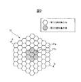
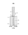
図2に、本実施の形態における原子炉の炉心の概略平面図を示す。図3に、本実施の形態における原子炉の炉心の概略断面図を示す。図3は、図2におけるA-A線に沿って切断したときの断面図である。図3は、原子炉の出力運転の期間中の状態を示している。
図2および図3を参照して、本実施の形態における炉心10は、平面形状がほぼ正六角形状に形成されている。原子炉の炉心は、この形態に限られず、平面視したときに、ほぼ円形となる任意の形状または円形に形成することができる。
本実施の形態における炉心10は、平面視したときに中央領域および周辺領域に区画されている。本実施の形態における炉心10は、複数の燃料集合体を含む。本実施の形態における原子炉の炉心10は、燃料集合体が規則的に配列されている。炉心の周辺領域には、第1の燃料集合体としての燃料集合体21aが配置されている。炉心の中央領域には、第2の燃料集合体としての燃料集合体21bが配置されている。
本実施の形態における燃料集合体21aと燃料集合体21bとは、同一の新燃料が装荷されている。本実施の形態においては、劣化ウランが装荷されている。また、燃料集合体21aと燃料集合体21bとは、燃料を支持するための構造がほぼ同一である。本実施の形態における燃料集合体21aと燃料集合体21bとは、互いに同じ高さになるように形成されている。周辺領域に配置されている燃料集合体21aは、炉心10に固定されている。一方で、中央領域に配置されている燃料集合体21bは、後述するように炉心の軸方向に移動可能に形成されている。本実施の形態における炉心は、鉛直方向が炉心の軸方向に相当する。
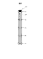
図4に、本実施の形態における燃料集合体の概略斜視図を示す。以下においては、第1の燃料集合体としての燃料集合体21aについて説明するが、第2の燃料集合体としての燃料集合体21bについても燃料集合体21aと同様の構造を有する。
燃料集合体21aは、複数の燃料棒22aを含む。燃料棒22aは、長手方向の端部がノズル27により支持されている。燃料棒22aは、複数の支持格子25により支持されている。ノズル27および支持格子25は、燃料棒22a同士を互いに離して支持している。本実施の形態では支持格子により燃料棒同士の間の距離を保っているが、この形態に限られず、支持格子の代わりにワイヤースペーサー等を用いることができる。冷却材は、燃料棒22a同士の間を流れて燃料棒22aを冷却する。
図5に、本実施の形態における燃料棒の概略斜視図を示す。図5では、燃料の燃焼が上側から下側に向かって移動する燃料棒を示している。また、被覆材の一部を破断して示している。本実施の形態における燃料棒22aは、被覆材23aを含む。被覆材23aは、筒状に形成されている。被覆材23aは、たとえばステンレス鋼で形成されている。燃料棒22aは、燃料ペレット24aa,24ab,24acを含む。燃料ペレット24aa,24ab,24acは、被覆材23aの内部に配置されている。燃料棒22aは、栓29により封止されている。燃料ペレット24aa,24ab,24acは、コイルスプリング28により押圧されている。
図5に示す燃料棒は、燃焼サイクル初期の状態を示している。複数の燃料ペレット24aa,24ab,24acは、新燃料を含む燃料ペレット24aa、燃焼途中の燃料ペレット24ab、および燃焼が十分に進んだ燃料ペレット24acの順に配置されている。新燃料を含む燃料ペレット24aaの部分により、炉心の新燃料部が画定される。燃焼途中の燃料ペレット24abの部分により、炉心の燃焼部が画定される。燃焼が進んだ燃料ペレット24acの部分により、炉心の燃焼が進んだ部分が画定される。
このように、本実施の形態における燃料棒22aには、燃焼度が互いに異なる燃料ペレット24aa,24ab,24acが配置されている。一つの燃焼サイクルが終了した後には、たとえば、被覆材23aを剥ぎ取り、燃焼が進んだ部分の燃料ペレットとそれ以外の燃料ペレットとを分離する。次に、新たな被覆材の内部に、新燃料を含む燃料ペレットおよび回収された燃料ペレット等を配置することにより、次の燃焼サイクルのための燃料棒を形成することができる。
または、燃料ペレットの回収方法としては、それぞれの部分ごとに燃料棒を切断した後に、被覆材23aを剥ぎ取っても構わない。この方法によっても、燃焼部および燃焼が進んだ部分に配置されていた燃料ペレットを回収することができる。
図2から図5を参照して、本実施の形態における燃料集合体21aおよび燃料集合体21bの新燃料部に配置される燃料ペレットは、劣化ウランを含む。本実施の形態における燃料は、金属燃料であるが、この形態に限られず、例えば、窒化物燃料等を用いることができる。
図1および図3を参照して、本実施の形態における原子炉は、中性子を吸収するための補助部材51を備える。本実施の形態における補助部材51は、中性子を吸収する機能を有する吸収物質を含む。吸収物質としては、高速中性子の吸収能力が高い物質が好ましい。吸収物質としては、例えば、炭化ほう素(B4C)等を例示することができる。
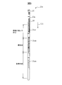
図6に、本実施の形態における移動可能な燃料集合体および補助部材の概略斜視図を示す。本実施の形態における補助部材51は、被覆材の内部に燃料が配置されずに、中性子を吸収する機能を有する吸収物質が配置されていること以外は、燃料集合体21a,21bと同様の構成を有する。
補助部材51は、複数の吸収棒52を含む。吸収棒52は、被覆材を有し、被覆材の内部には、吸収物質が配置されている。補助部材51は、吸収棒52を支持するための支持格子25およびノズル27を有する。これらの支持格子25およびノズル27は、燃料集合体21a,21bに用いるものの同様のものを採用することができる。
補助部材51は、燃料集合体21bに連結されている。燃料集合体21bは、複数の燃料棒22bを含む。本実施の形態においては、燃料集合体21bは、連結部材61を介して補助部材51に連結されている。燃料集合体21bは、補助部材51に炉心の軸方向に直列に接続されている。
図1および図3を参照して、本実施の形態における原子炉は、燃料集合体21bを移動させるための移動装置を備える。移動装置は、燃料集合体21bを移動させるための駆動装置71を含む。補助部材51は、連結部材62を介して駆動棒72に接続されている。駆動装置71を始動することにより、駆動棒72が矢印123に示すように炉心10の軸方向に移動する。補助部材51および燃料集合体21bを、炉心の軸方向に移動させることができる。
次に、本実施の形態における炉心の出力運転について説明する。本実施の形態においては、出力運転中にほぼ一定の出力に保たれる例について説明する。
図7に、本実施の形態における炉心の燃焼の進行状況を説明する模式図を示す。図7は、炉心を軸方向に沿って切断したときの概略断面図である。図7は、複数回の燃焼サイクルを行なった後の第nサイクルの初期(BOC)の炉心と、第nサイクルの末期(EOC)の炉心とを示している。また、同一のサイクル長さおよび同一の燃料取替え方法で複数サイクル運転を行なった炉心を示している。径方向の位置rが零の軸が炉心軸である。
本実施の形態における原子炉の炉心10は、燃焼サイクルの初期から末期にかけて燃焼部12が、新燃料部11に向けて移動する。すなわち、本実施の形態における炉心は、CANDLE燃焼を行なう。燃焼部12の移動する速度は、凡そ出力密度に比例し、燃料原子数密度に反比例する。
本実施の形態における炉心の出力密度は、炉心の中央において高くなる。炉心の外周においては、中性子の漏れが多くなるために、径方向の外側に向かうほど出力密度が小さくなる。このため、燃焼部の軸方向の位置は、径方向の外側に向かうほど遅れた位置に配置される。
本実施の形態における炉心10は、新燃料部11、燃焼部12および燃焼が進んだ部分13を含む。新燃料部11は、新燃料が配置されている部分である。燃焼部12は、自発的に中性子が発生し、燃料の燃焼が生じる部分である。燃焼部12では、核分裂が発生することにより実質に出力が生じている。燃焼が進んだ部分13は、燃焼が進んで、ほとんど出力を発生していない部分である。
第nサイクルの初期の炉心において、新燃料部11は、炉心10の下部に配置されている。燃焼部12は、新燃料部11の上側に配置されている。燃焼部12には、前サイクルで既に燃焼が始まっていた燃料が配置されている。
本実施の形態においては、サイクル初期に配置された燃焼部12は、燃焼を開始する部分になる。燃焼部12から燃料の燃焼が開始され、矢印101に示すように、新燃料部11に向かう方向に燃焼が進行する。第nサイクルの燃焼が進行してサイクル末期になった場合には、燃焼部12が炉心10の下端まで進行する。本実施の形態においては、新燃料部11がほとんどなくなるまで燃焼を継続している。燃焼サイクル末期では、新燃料部11が残っていても構わない。
図8に、本実施の形態における燃料の中性子フルエンスと無限中性子増倍率との関係を説明するグラフを示す。横軸が、中性子束を時間で積分した中性子フルエンスであり、縦軸が無限中性子増倍率kinfである。中性子フルエンスは、たとえば燃料の燃焼度に対応する量である。本実施の形態においては劣化ウランを燃料としている。劣化ウランは、たとえば、約99.8%のウラン238と、約0.2%のウラン235とを含む。ウラン238は、中性子を吸収することにより次の数1のように核変換する。ウラン238は、プルトニウム239に変換される。

中性子フルエンスが零の近傍では、ウラン238が中性子を吸収してプルトニウム239が生成されることにより、無限中性子増倍率が上昇する。所定の中性子フルエンスに達すると、プルトニウム239等の存在量のウラン238の存在量に対する比が一定に近づき、更に核分裂生成物(FP)が蓄積して、無限中性子増倍率が徐々に減少する。このように、本実施の形態における燃料は、燃焼の初期において無限中性子増倍率が増加し、その後に徐々に無限中性子増倍率が減少する特性を有する。
また、劣化ウランの未臨界度は大きいために、炉心の一部分を臨界以上にするためには、多くの中性子をウラン238に吸収させる必要がある。本実施の形態においては、このような条件を満たすように炉心の大きさを選定するとともに燃料集合体や燃料棒を設計している。
上記のような炉心の構成を採用することにより、CANDLE燃焼を実施することができる。すなわち、炉心の径方向の全体にわたって出力が生じ、炉心の軸方向の一部の領域において燃焼部が生成される炉心を形成することができる。
図9に、炉心高さを無限大にして燃焼を行なっているときの無限中性子増倍率のグラフを示す。横軸が炉心高さであり、縦軸が燃料の無限中性子増倍率を示している。本実施の形態においては、矢印101に示すように、燃焼部が新燃料部に向かって移動する。燃焼部は、無限中性子増倍率が1を超える領域を含む。実際の原子炉の炉心の高さは有限であり、この場合には、炉心の端部での無限中性子増倍率は、図9に示すグラフから僅かにずれる場合がある。
図10に、本実施の形態における炉心の燃焼が進行する状態および燃料取り換えを説明するグラフを示す。図10には、第nサイクルの炉心の初期および末期のグラフと、第(n+1)サイクルの炉心の初期および末期のグラフが示されている。それぞれのグラフにおいては、炉心軸における出力密度、ウラン238の数密度および核分裂生成物の数密度が示されている。
図9および図10を参照して、出力密度の最大点は、矢印101に示すように、新燃料部11が配置されている炉心下部に向けて移動する。本実施の形態における燃焼は、炉心の上端から下端に向かう方向に移動する。燃焼部が移動していく速度、すなわち、出力密度の最大点が移動する速度は、例えば、1年間に数cmである。このように、ゆっくりと燃焼部が移動する。ウラン238の数密度は、核変換されることにより燃焼部の下流側で小さくなる。また、核分裂生成物の数密度は、核分裂が生じることにより燃焼部の下流側で大きくなる。本実施の形態においては、燃焼部が、炉心のほぼ下端に達したときに燃焼を終了している。
第nサイクルが終了すると燃料が進んだ部分の一部の燃料を取り出す。第(n+1)サイクルの初期の炉心では、矢印117に示すように、第nサイクルにおいて炉心の下部に配置されている燃焼部を炉心の上部に配置して、燃焼を開始する部分として使用する。第(n+1)サイクルの炉心においては、炉心の下部に新たな新燃料部11を配置する。このような燃料交換を行なうことにより、第(n+1)サイクルの炉心においても、第nサイクルの炉心と同様の燃焼を行なうことができる。
次に、本実施の形態における原子炉の停止について説明する。図1から図3を参照して、通常の出力運転の期間中において、燃料集合体21bは、炉心10の内部に配置されている。原子炉を停止すべきときには、駆動装置71を駆動することにより、矢印121に示すように、補助部材51と燃料集合体21bとを一体的に移動させる。燃料集合体21bは、炉心10の内部から外部に移動する。一方で、補助部材51が炉心10の内部に挿入される。すなわち、移動可能な燃料集合体21bが炉心10から引き抜かれるとともに、補助部材51が炉心10に挿入される。
図11に、本実施の形態の炉心において、原子炉を停止した時の炉心の部分の概略断面図を示す。本実施の形態における炉心は、移動可能な燃料集合体21bの全体が、炉心10から引き抜かれている。また、補助部材51が炉心に挿入されている。
燃料集合体21bが炉心10から引き抜かれることにより、炉心10からの中性子の漏れが多くなり、炉心10を未臨界にして停止することができる。図7を参照して、本実施の形態における炉心10は、燃焼部12の部分において、連鎖的な核分裂が生じることにより臨界を保っている。ところが、燃料集合体21bを移動することにより、燃焼部12の一部が炉心10の軸方向にずれることになり、燃焼部12における核分裂の連鎖が抑制される。このために、炉心10を未臨界にすることができる。
また、本実施の形態の炉心10においては、原子炉を停止するときに補助部材51が炉心10に挿入される。補助部材51が炉心に挿入されることにより、中性子が補助部材51に吸収される。このために、より確実に原子炉を停止させることができる。
本実施の形態においては、移動可能な燃料集合体の全体が炉心から引き抜かれるように形成されている。この構成により、より確実に原子炉を停止することができる。移動可能な燃料の引抜き量については、この形態に限られず、移動可能な燃料集合体の一部を引き抜くことにより原子炉を停止することができる場合には、炉心から燃料集合体の一部が引き抜かれるように形成されていても構わない。
次に、本実施の形態における原子炉の起動について説明する。原子炉の起動時には、燃料の交換が行なわれた燃料集合体のうち、移動可能な燃料集合体を炉心に挿入することにより、臨界の達成および出力の上昇を行う。
図12に、本実施の形態の原子炉において、原子炉を起動している途中の炉心の部分の概略断面図を示す。前述したように、第nサイクルが終了すると、それぞれの燃料集合体21a,21bにおいて、燃焼が進んだ部分13の燃料を取り出して新燃料部11に新燃料を装荷する。
図11および図12を参照して、原子炉を起動すべき時には、移動可能な燃料集合体21bの少なくとも一部分が炉心10から引き抜かれている。燃料集合体21bを、矢印122に示すように移動して、炉心10の内部に挿入する。燃料集合体21bを挿入すると、所定の位置において炉心10が臨界になる。さらに、燃料集合体21bを挿入すると、炉心10の出力が上昇する。燃料集合体21b全体を挿入することにより、炉心の出力が予め定められた出力に到達する。この後に定常的な出力運転を継続することができる。
燃料集合体21bを炉心10に挿入する場合に、高速で燃料集合体21bを移動すると、炉心10に大きな正の反応度が印加されて、出力が急上昇する場合がある。このため、燃料集合体21bを炉心10に挿入するときには、低速で燃料集合体21bを移動することが好ましい。または、燃料集合体21bを徐々に挿入することが好ましい。例えば、炉心の出力が予め定められた上昇速度となるように、徐々に燃料集合体21bを炉心10に挿入することが好ましい。
本実施の形態における原子炉の炉心は、制御棒を使用しなくても、原子炉の起動および原子炉の停止を行なうことができる。制御棒を炉心10に挿入するための流路が不要であり、中性子の漏れを抑制することができる。このために、CANDLE燃焼による炉心の臨界を容易に達成することができる。さらに、炉心の平均出力密度を高くすることができる。
また、炉心10に、制御棒が挿入される流路を形成すると、その流路の近傍において炉心の軸方向に出力密度を積分した値が小さくなる。ここで、本実施の形態においては、径方向の任意の位置において出力密度を炉心の軸方向に積分した値を軸方向積分出力という。制御棒を挿入するための流路には燃料が装荷されていないために、軸方向積分出力が小さくなってしまう。このために、制御棒を挿入する流路の近傍に配置されている燃料の燃焼度が小さくなる。炉心の径方向において燃料の燃焼が不均一になる。
本実施の形態における炉心では、制御棒が挿入される流路を排除することができるために、径方向において軸方向積分出力をほぼ一定に近づけることができる。すなわち、径方向の出力分布を一定に近づけることができる。より一様に燃料を燃焼させることができる。また、径方向の出力分布を一定に近づけることができるため、例えば、運転制御が容易になったり、原子炉の設計が容易になったりする。
本実施の形態の炉心においては、移動可能な燃料集合体と補助部材を備え、燃料集合体が炉心から引き抜かれるとともに、補助部材が炉心に挿入されるように形成されているが、この形態に限られず、移動可能な燃料集合体を引き抜いたり挿入したりすることにより、原子炉の停止および起動を行うことができれば、補助部材が配置されていなくても構わない。たとえば、一部の燃料集合体を炉心から引き抜くことにより、炉心からの中性子の漏れを増加させるとともに、炉心に配置されているウランの量を少なくすることができる。このために、炉心に大きな負の反応度を印加することができ、原子炉の構造によっては、補助部材を配置しなくても原子炉の停止および起動を行うことができる。
また、本実施の形態における補助部材は、中性子を吸収する機能を有する吸収物質が含まれているが、この形態に限られず、原子炉を停止することができれば、吸収物質が含まれていなくても構わない。吸収物質が配置されていなくても、補助部材を炉心に挿入することにより、炉心の機械的な強度を維持することができる。
上記の炉心においては、移動可能な燃料集合体が中央領域に配置されて、炉心に固定されている燃料集合体が周辺領域に配置されている。この構成により、燃料集合体を移動させる移動装置の構成を簡易にすることができる。このような炉心は、例えば、燃料集合体の数が少ない小型の炉心に好適である。
本実施の形態における炉心は、中央領域の燃料集合体を炉心から引き抜く様に形成されているが、この形態に限られず、周辺領域に配置されている燃料集合体を炉心から引き抜くように形成されていても構わない。燃料集合体を引き抜く燃料集合体の本数は、原子炉の起動および停止が可能なように定めることができる。また、移動可能な燃料集合体の配置としては、上記の形態に限られず、任意の位置に配置することができる。
図13は、本実施の形態における他の炉心の概略平面図である。第2の燃料集合体としての移動可能な燃料集合体21bは、炉心10の全体にわたって、ほぼ均等に配置されている。複数の燃料集合体21bは、予め定められた間隔をあけて、互いに接触せずに配置されている。複数の燃料集合体21bは、離散して配置されている。この構成を採用することによっても、燃料集合体21bを移動することにより、原子炉の停止や原子炉の起動を行なうことができる。このような移動可能な燃料集合体を離散して配置する構成は、特に、大型の炉心に好適である。
本実施の形態における炉心は、移動可能な燃料集合体を下側に向かって引き抜く様に形成されているが、この形態に限られず、移動可能な燃料集合体は、炉心の上側に向かって引き抜くように形成されていても構わない。
また、本実施の形態における燃料集合体は、正六角柱状に形成されているが、この形態に限られず、任意の形状の燃料集合体を採用することができる。例えば、燃料集合体の引抜きまたは挿入が容易になるように、燃料集合体は、長手方向に沿って径方向の長さが徐々に変化するテーパ形状に形成されていて構わない。
本実施の形態における補助部材は、被覆材の内部に配置されている物質以外は、燃料集合体と同様の構造を有するが、この形態に限られず、補助部材としては、任意の構造のものを採用することができる。被覆材の内部が空洞であっても構わない。
本実施の形態における燃料は、炉心に装荷する新燃料として劣化ウランを例に取り上げて説明したが、この形態に限られず、天然ウランおよび劣化ウランのうち少なくとも一方を用いて、CANDLE燃焼を達成することができる。また、CANDLE燃焼を行なうことができる任意の高速中性子炉に、本発明を適用することができる。
本実施の形態においては、燃焼サイクル初期において前サイクルの燃焼部を新燃料部の上側に配置したが、この形態に限られず、新燃料部は、炉心の軸方向のうち、燃焼部のいずれか一方の端部に配置することができる。さらには、燃焼部の両側に新燃料部が配置されていても構わない。
また、本実施の形態においては、サイクル初期の燃焼を開始する部分は、前サイクルのサイクル末期において、炉心の下部に配置されている燃料を使用しているが、この形態に限られず、サイクル初期における燃焼を開始する部分は、中性子を自発的に発生するように形成されていれば構わない。たとえば、所定の濃度のプルトニウムや濃縮ウランなどを含む燃料が配置されていても構わない。更には、外部から中性子が供給されることにより、燃焼が開始されても構わない。
また、本実施の形態における炉心は、炉心の軸方向が鉛直方向と平行になっているが、この形態に限られず、炉心の軸方向は水平方向と平行になっていても構わない。すなわち、本実施の形態における炉心を横置きにしても構わない。
本実施の形態においては、燃料の燃焼が定常になっている時に、炉心に対して反応度の制御を行わない運転方法を例に取り上げて説明したが、この形態に限られず、反応度制御を行っても構わない。
本実施の形態においては、発電設備に用いられる原子炉の炉心を例に取り上げて説明したが、この形態に限られず、任意の設備の原子炉に本発明を適用することができる。たとえば、船舶等の動力源として本発明の原子炉を用いることができる。
上述のそれぞれの図において、同一または相当する部分には同一の符号を付している。なお、上記の実施の形態は例示であり発明を限定するものではない。また、実施の形態においては、請求の範囲に示される変更が含まれている。
1 原子炉
10 炉心
11 新燃料部
12 燃焼部
13 燃焼が進んだ部分
21a 燃料集合体
21b 燃料集合体
22a 燃料棒
23a 被覆材
24aa,24ab,24ac 燃料ペレット
51 補助部材
52 吸収棒
71 駆動装置
72 駆動棒
10 炉心
11 新燃料部
12 燃焼部
13 燃焼が進んだ部分
21a 燃料集合体
21b 燃料集合体
22a 燃料棒
23a 被覆材
24aa,24ab,24ac 燃料ペレット
51 補助部材
52 吸収棒
71 駆動装置
72 駆動棒
Claims (5)
- 新燃料が装荷されている新燃料部と、新燃料部の一方の側に配置され、中性子を発生して燃料が燃焼する燃焼部とを含み、新燃料は天然ウランおよび劣化ウランのうち少なくとも一方のウランを含み、ウランが中性子を吸収して生成されたプルトニウムが核分裂することにより出力を発生し、燃焼サイクルの初期から末期にかけて、燃焼部が新燃料部に向かう方向に移動する炉心を備える原子炉であって、
出力運転の期間中には、複数の燃料集合体が炉心に配置されており、
複数の燃料集合体は、炉心に固定されている燃料集合体および炉心の軸方向に移動可能な燃料集合体を含み、
移動可能な燃料集合体を炉心から引き抜くことにより原子炉を停止させ、更に移動可能な燃料集合体を引き抜いた状態から炉心に挿入することにより原子炉を起動することを特徴とする、原子炉。 - 中性子を吸収する機能を有する吸収物質を含む補助部材を備え、
補助部材は、移動可能な燃料集合体に連結されており、
原子炉を停止する場合には、移動可能な燃料集合体が炉心から引き抜かれると共に、補助部材が炉心に挿入されることを特徴とする、請求項1に記載の原子炉。 - 移動可能な燃料集合体は、炉心から燃料集合体の全体が引き抜かれるように形成されていることを特徴とする、請求項1に記載の原子炉。
- 炉心は、中央領域および周辺領域に区画されており、
移動可能な燃料集合体は、中央領域に配置され、
炉心に固定されている燃料集合体は、周辺領域に配置されていることを特徴とする、請求項1に記載の原子炉。 - 移動可能な燃料集合体は、予め定められた間隔をあけて離散して炉心に配置されていることを特徴とする、請求項1に記載の原子炉。
Priority Applications (3)
| Application Number | Priority Date | Filing Date | Title |
|---|---|---|---|
| US13/978,565 US20130294559A1 (en) | 2011-01-07 | 2012-01-05 | Nuclear reactor |
| CN201280004627.3A CN103299374B (zh) | 2011-01-07 | 2012-01-05 | 原子反应堆 |
| EP12732268.3A EP2662863A4 (en) | 2011-01-07 | 2012-01-05 | Nuclear reactor |
Applications Claiming Priority (2)
| Application Number | Priority Date | Filing Date | Title |
|---|---|---|---|
| JP2011-001865 | 2011-01-07 | ||
| JP2011001865A JP5807868B2 (ja) | 2011-01-07 | 2011-01-07 | 原子炉 |
Publications (1)
| Publication Number | Publication Date |
|---|---|
| WO2012093700A1 true WO2012093700A1 (ja) | 2012-07-12 |
Family
ID=46457550
Family Applications (1)
| Application Number | Title | Priority Date | Filing Date |
|---|---|---|---|
| PCT/JP2012/050112 Ceased WO2012093700A1 (ja) | 2011-01-07 | 2012-01-05 | 原子炉 |
Country Status (5)
| Country | Link |
|---|---|
| US (1) | US20130294559A1 (ja) |
| EP (1) | EP2662863A4 (ja) |
| JP (1) | JP5807868B2 (ja) |
| CN (1) | CN103299374B (ja) |
| WO (1) | WO2012093700A1 (ja) |
Families Citing this family (7)
| Publication number | Priority date | Publication date | Assignee | Title |
|---|---|---|---|---|
| US9831004B2 (en) * | 2006-11-28 | 2017-11-28 | Terrapower, Llc | Controllable long term operation of a nuclear reactor |
| US10593436B2 (en) * | 2013-11-21 | 2020-03-17 | Terrapower, Llc | Method and system for generating a nuclear reactor core loading distribution |
| CN104464842B (zh) * | 2014-12-22 | 2017-02-22 | 中国科学院合肥物质科学研究院 | 加速器驱动铅铋冷却次临界行波堆 |
| KR101879428B1 (ko) | 2017-03-23 | 2018-07-17 | 한국전력기술 주식회사 | 슬라이딩 도어를 이용한 원자로 이차 정지구조 |
| CN107507653A (zh) * | 2017-08-29 | 2017-12-22 | 华北电力大学 | 一种铅冷快堆可分离堆芯实施方案 |
| CN107578825A (zh) * | 2017-09-19 | 2018-01-12 | 中广核研究院有限公司 | 反应堆堆芯结构及其启停堆控制方式 |
| CN111739666B (zh) * | 2020-06-23 | 2021-12-31 | 上海交通大学 | 一种用于空间探索的行波堆 |
Citations (2)
| Publication number | Priority date | Publication date | Assignee | Title |
|---|---|---|---|---|
| JP2002071866A (ja) * | 2000-08-30 | 2002-03-12 | Tokyo Inst Of Technol | 原子炉の炉心およびその炉心における核燃料物質の取替方法 |
| JP2007232429A (ja) * | 2006-02-28 | 2007-09-13 | Tokyo Institute Of Technology | 原子炉の運転方法 |
Family Cites Families (6)
| Publication number | Priority date | Publication date | Assignee | Title |
|---|---|---|---|---|
| US2954335A (en) * | 1946-02-04 | 1960-09-27 | Eugene P Wigner | Neutronic reactor |
| US2841545A (en) * | 1954-06-15 | 1958-07-01 | Walter H Zinn | Power reactor |
| US3671392A (en) * | 1971-03-15 | 1972-06-20 | Atomic Energy Commission | Light-water breeder reactor |
| JP2001099974A (ja) * | 1999-09-29 | 2001-04-13 | Toshiba Corp | 制御棒駆動装置、その運転方法、その試験方法及びその試験装置、その点検装置、その保管方法及びその保管装置並びにトルク伝達装置及びその試験方法 |
| US7860207B2 (en) * | 2006-11-28 | 2010-12-28 | The Invention Science Fund I, Llc | Method and system for providing fuel in a nuclear reactor |
| JP5398254B2 (ja) * | 2008-12-19 | 2014-01-29 | 株式会社東芝 | 制御棒・燃料支持金具取扱装置 |
-
2011
- 2011-01-07 JP JP2011001865A patent/JP5807868B2/ja not_active Expired - Fee Related
-
2012
- 2012-01-05 CN CN201280004627.3A patent/CN103299374B/zh not_active Expired - Fee Related
- 2012-01-05 WO PCT/JP2012/050112 patent/WO2012093700A1/ja not_active Ceased
- 2012-01-05 EP EP12732268.3A patent/EP2662863A4/en not_active Withdrawn
- 2012-01-05 US US13/978,565 patent/US20130294559A1/en not_active Abandoned
Patent Citations (3)
| Publication number | Priority date | Publication date | Assignee | Title |
|---|---|---|---|---|
| JP2002071866A (ja) * | 2000-08-30 | 2002-03-12 | Tokyo Inst Of Technol | 原子炉の炉心およびその炉心における核燃料物質の取替方法 |
| JP3463100B2 (ja) | 2000-08-30 | 2003-11-05 | 東京工業大学長 | 原子炉の炉心における核燃料物質の取替方法 |
| JP2007232429A (ja) * | 2006-02-28 | 2007-09-13 | Tokyo Institute Of Technology | 原子炉の運転方法 |
Non-Patent Citations (1)
| Title |
|---|
| See also references of EP2662863A4 * |
Also Published As
| Publication number | Publication date |
|---|---|
| JP2012145353A (ja) | 2012-08-02 |
| EP2662863A1 (en) | 2013-11-13 |
| CN103299374A (zh) | 2013-09-11 |
| US20130294559A1 (en) | 2013-11-07 |
| JP5807868B2 (ja) | 2015-11-10 |
| EP2662863A4 (en) | 2017-11-15 |
| CN103299374B (zh) | 2016-06-08 |
Similar Documents
| Publication | Publication Date | Title |
|---|---|---|
| JP5807868B2 (ja) | 原子炉 | |
| EP2889878B1 (en) | Burnable absorber-integrated control rod guide thimble | |
| EP2887357B1 (en) | Nuclear reactor fluence reduction systems and methods | |
| KR102605338B1 (ko) | 도플러 반응도 증대 장치 | |
| JP5716920B2 (ja) | 原子炉の炉心および原子炉 | |
| JP2007232429A (ja) | 原子炉の運転方法 | |
| JP5947733B2 (ja) | 高速炉の炉心 | |
| JP2002071866A (ja) | 原子炉の炉心およびその炉心における核燃料物質の取替方法 | |
| JP5006233B2 (ja) | トリウム系核燃料を用いた増殖可能な核燃料集合体。 | |
| US9543045B2 (en) | Nuclear reactor and power generation facility | |
| JP2012145552A (ja) | 原子炉の炉心および原子炉 | |
| JP5717091B2 (ja) | 原子炉を備える設備 | |
| KR20140096807A (ko) | 원자력발전소 사용후핵연료를 이용한 초장주기 고속로 | |
| RU2013135377A (ru) | Способ эксплуатации ядерного реактора в ториевом топливном цикле с расширенным воспроизводством изотопа 233u | |
| Hartanto et al. | An optimization study on the excess reactivity in a linear breed-and-burn fast reactor (B&BR) | |
| JP2012167953A (ja) | 原子炉の炉心および原子炉 | |
| JP3062770B2 (ja) | 燃料集合体の構造 | |
| JP2006064678A (ja) | 原子炉の燃料集合体配置方法、燃料棒および燃料集合体 | |
| JP2017032408A (ja) | 超ウラン元素変換燃料集合体、超ウラン元素変換炉心および超ウラン元素変換燃料集合体設計方法 | |
| Hartanto et al. | A physics study on alternative reflectors in a compact sodium-cooled breed-and-burn fast reactor | |
| JP7278937B2 (ja) | 核燃料要素の製造方法 | |
| JP3993624B2 (ja) | 原子炉用燃料集合体の余剰反応度制御方法 | |
| JP2012207962A (ja) | 原子炉の燃料要素の製造方法 | |
| Obara et al. | Small Reactor for Semiconductor Production by Neutron Transmutation Doping | |
| JPS59188592A (ja) | 原子炉の燃焼制御方法及び装置 |
Legal Events
| Date | Code | Title | Description |
|---|---|---|---|
| 121 | Ep: the epo has been informed by wipo that ep was designated in this application |
Ref document number: 12732268 Country of ref document: EP Kind code of ref document: A1 |
|
| NENP | Non-entry into the national phase |
Ref country code: DE |
|
| WWE | Wipo information: entry into national phase |
Ref document number: 13978565 Country of ref document: US |
|
| WWE | Wipo information: entry into national phase |
Ref document number: 2012732268 Country of ref document: EP |