WO2012095964A1 - 車両用情報処理システム - Google Patents
車両用情報処理システム Download PDFInfo
- Publication number
- WO2012095964A1 WO2012095964A1 PCT/JP2011/050368 JP2011050368W WO2012095964A1 WO 2012095964 A1 WO2012095964 A1 WO 2012095964A1 JP 2011050368 W JP2011050368 W JP 2011050368W WO 2012095964 A1 WO2012095964 A1 WO 2012095964A1
- Authority
- WO
- WIPO (PCT)
- Prior art keywords
- information
- deceleration
- vehicle
- pattern
- support
- Prior art date
- Legal status (The legal status is an assumption and is not a legal conclusion. Google has not performed a legal analysis and makes no representation as to the accuracy of the status listed.)
- Ceased
Links
Images





Classifications
-
- B—PERFORMING OPERATIONS; TRANSPORTING
- B60—VEHICLES IN GENERAL
- B60W—CONJOINT CONTROL OF VEHICLE SUB-UNITS OF DIFFERENT TYPE OR DIFFERENT FUNCTION; CONTROL SYSTEMS SPECIALLY ADAPTED FOR HYBRID VEHICLES; ROAD VEHICLE DRIVE CONTROL SYSTEMS FOR PURPOSES NOT RELATED TO THE CONTROL OF A PARTICULAR SUB-UNIT
- B60W40/00—Estimation or calculation of non-directly measurable driving parameters for road vehicle drive control systems not related to the control of a particular sub unit, e.g. by using mathematical models
- B60W40/08—Estimation or calculation of non-directly measurable driving parameters for road vehicle drive control systems not related to the control of a particular sub unit, e.g. by using mathematical models related to drivers or passengers
-
- B—PERFORMING OPERATIONS; TRANSPORTING
- B60—VEHICLES IN GENERAL
- B60L—PROPULSION OF ELECTRICALLY-PROPELLED VEHICLES; SUPPLYING ELECTRIC POWER FOR AUXILIARY EQUIPMENT OF ELECTRICALLY-PROPELLED VEHICLES; ELECTRODYNAMIC BRAKE SYSTEMS FOR VEHICLES IN GENERAL; MAGNETIC SUSPENSION OR LEVITATION FOR VEHICLES; MONITORING OPERATING VARIABLES OF ELECTRICALLY-PROPELLED VEHICLES; ELECTRIC SAFETY DEVICES FOR ELECTRICALLY-PROPELLED VEHICLES
- B60L15/00—Methods, circuits, or devices for controlling the traction-motor speed of electrically-propelled vehicles
- B60L15/20—Methods, circuits, or devices for controlling the traction-motor speed of electrically-propelled vehicles for control of the vehicle or its driving motor to achieve a desired performance, e.g. speed, torque, programmed variation of speed
- B60L15/2009—Methods, circuits, or devices for controlling the traction-motor speed of electrically-propelled vehicles for control of the vehicle or its driving motor to achieve a desired performance, e.g. speed, torque, programmed variation of speed for braking
-
- B—PERFORMING OPERATIONS; TRANSPORTING
- B60—VEHICLES IN GENERAL
- B60L—PROPULSION OF ELECTRICALLY-PROPELLED VEHICLES; SUPPLYING ELECTRIC POWER FOR AUXILIARY EQUIPMENT OF ELECTRICALLY-PROPELLED VEHICLES; ELECTRODYNAMIC BRAKE SYSTEMS FOR VEHICLES IN GENERAL; MAGNETIC SUSPENSION OR LEVITATION FOR VEHICLES; MONITORING OPERATING VARIABLES OF ELECTRICALLY-PROPELLED VEHICLES; ELECTRIC SAFETY DEVICES FOR ELECTRICALLY-PROPELLED VEHICLES
- B60L15/00—Methods, circuits, or devices for controlling the traction-motor speed of electrically-propelled vehicles
- B60L15/20—Methods, circuits, or devices for controlling the traction-motor speed of electrically-propelled vehicles for control of the vehicle or its driving motor to achieve a desired performance, e.g. speed, torque, programmed variation of speed
- B60L15/2045—Methods, circuits, or devices for controlling the traction-motor speed of electrically-propelled vehicles for control of the vehicle or its driving motor to achieve a desired performance, e.g. speed, torque, programmed variation of speed for optimising the use of energy
-
- B—PERFORMING OPERATIONS; TRANSPORTING
- B60—VEHICLES IN GENERAL
- B60W—CONJOINT CONTROL OF VEHICLE SUB-UNITS OF DIFFERENT TYPE OR DIFFERENT FUNCTION; CONTROL SYSTEMS SPECIALLY ADAPTED FOR HYBRID VEHICLES; ROAD VEHICLE DRIVE CONTROL SYSTEMS FOR PURPOSES NOT RELATED TO THE CONTROL OF A PARTICULAR SUB-UNIT
- B60W10/00—Conjoint control of vehicle sub-units of different type or different function
- B60W10/04—Conjoint control of vehicle sub-units of different type or different function including control of propulsion units
- B60W10/06—Conjoint control of vehicle sub-units of different type or different function including control of propulsion units including control of combustion engines
-
- B—PERFORMING OPERATIONS; TRANSPORTING
- B60—VEHICLES IN GENERAL
- B60W—CONJOINT CONTROL OF VEHICLE SUB-UNITS OF DIFFERENT TYPE OR DIFFERENT FUNCTION; CONTROL SYSTEMS SPECIALLY ADAPTED FOR HYBRID VEHICLES; ROAD VEHICLE DRIVE CONTROL SYSTEMS FOR PURPOSES NOT RELATED TO THE CONTROL OF A PARTICULAR SUB-UNIT
- B60W10/00—Conjoint control of vehicle sub-units of different type or different function
- B60W10/04—Conjoint control of vehicle sub-units of different type or different function including control of propulsion units
- B60W10/08—Conjoint control of vehicle sub-units of different type or different function including control of propulsion units including control of electric propulsion units, e.g. motors or generators
-
- B—PERFORMING OPERATIONS; TRANSPORTING
- B60—VEHICLES IN GENERAL
- B60W—CONJOINT CONTROL OF VEHICLE SUB-UNITS OF DIFFERENT TYPE OR DIFFERENT FUNCTION; CONTROL SYSTEMS SPECIALLY ADAPTED FOR HYBRID VEHICLES; ROAD VEHICLE DRIVE CONTROL SYSTEMS FOR PURPOSES NOT RELATED TO THE CONTROL OF A PARTICULAR SUB-UNIT
- B60W20/00—Control systems specially adapted for hybrid vehicles
-
- B—PERFORMING OPERATIONS; TRANSPORTING
- B60—VEHICLES IN GENERAL
- B60W—CONJOINT CONTROL OF VEHICLE SUB-UNITS OF DIFFERENT TYPE OR DIFFERENT FUNCTION; CONTROL SYSTEMS SPECIALLY ADAPTED FOR HYBRID VEHICLES; ROAD VEHICLE DRIVE CONTROL SYSTEMS FOR PURPOSES NOT RELATED TO THE CONTROL OF A PARTICULAR SUB-UNIT
- B60W30/00—Purposes of road vehicle drive control systems not related to the control of a particular sub-unit, e.g. of systems using conjoint control of vehicle sub-units
- B60W30/14—Adaptive cruise control
- B60W30/143—Speed control
-
- B—PERFORMING OPERATIONS; TRANSPORTING
- B60—VEHICLES IN GENERAL
- B60W—CONJOINT CONTROL OF VEHICLE SUB-UNITS OF DIFFERENT TYPE OR DIFFERENT FUNCTION; CONTROL SYSTEMS SPECIALLY ADAPTED FOR HYBRID VEHICLES; ROAD VEHICLE DRIVE CONTROL SYSTEMS FOR PURPOSES NOT RELATED TO THE CONTROL OF A PARTICULAR SUB-UNIT
- B60W50/00—Details of control systems for road vehicle drive control not related to the control of a particular sub-unit, e.g. process diagnostic or vehicle driver interfaces
- B60W50/0097—Predicting future conditions
-
- B—PERFORMING OPERATIONS; TRANSPORTING
- B60—VEHICLES IN GENERAL
- B60W—CONJOINT CONTROL OF VEHICLE SUB-UNITS OF DIFFERENT TYPE OR DIFFERENT FUNCTION; CONTROL SYSTEMS SPECIALLY ADAPTED FOR HYBRID VEHICLES; ROAD VEHICLE DRIVE CONTROL SYSTEMS FOR PURPOSES NOT RELATED TO THE CONTROL OF A PARTICULAR SUB-UNIT
- B60W50/00—Details of control systems for road vehicle drive control not related to the control of a particular sub-unit, e.g. process diagnostic or vehicle driver interfaces
- B60W50/0098—Details of control systems ensuring comfort, safety or stability not otherwise provided for
-
- B—PERFORMING OPERATIONS; TRANSPORTING
- B60—VEHICLES IN GENERAL
- B60L—PROPULSION OF ELECTRICALLY-PROPELLED VEHICLES; SUPPLYING ELECTRIC POWER FOR AUXILIARY EQUIPMENT OF ELECTRICALLY-PROPELLED VEHICLES; ELECTRODYNAMIC BRAKE SYSTEMS FOR VEHICLES IN GENERAL; MAGNETIC SUSPENSION OR LEVITATION FOR VEHICLES; MONITORING OPERATING VARIABLES OF ELECTRICALLY-PROPELLED VEHICLES; ELECTRIC SAFETY DEVICES FOR ELECTRICALLY-PROPELLED VEHICLES
- B60L2240/00—Control parameters of input or output; Target parameters
- B60L2240/60—Navigation input
- B60L2240/62—Vehicle position
- B60L2240/622—Vehicle position by satellite navigation
-
- B—PERFORMING OPERATIONS; TRANSPORTING
- B60—VEHICLES IN GENERAL
- B60L—PROPULSION OF ELECTRICALLY-PROPELLED VEHICLES; SUPPLYING ELECTRIC POWER FOR AUXILIARY EQUIPMENT OF ELECTRICALLY-PROPELLED VEHICLES; ELECTRODYNAMIC BRAKE SYSTEMS FOR VEHICLES IN GENERAL; MAGNETIC SUSPENSION OR LEVITATION FOR VEHICLES; MONITORING OPERATING VARIABLES OF ELECTRICALLY-PROPELLED VEHICLES; ELECTRIC SAFETY DEVICES FOR ELECTRICALLY-PROPELLED VEHICLES
- B60L2250/00—Driver interactions
- B60L2250/26—Driver interactions by pedal actuation
-
- B—PERFORMING OPERATIONS; TRANSPORTING
- B60—VEHICLES IN GENERAL
- B60L—PROPULSION OF ELECTRICALLY-PROPELLED VEHICLES; SUPPLYING ELECTRIC POWER FOR AUXILIARY EQUIPMENT OF ELECTRICALLY-PROPELLED VEHICLES; ELECTRODYNAMIC BRAKE SYSTEMS FOR VEHICLES IN GENERAL; MAGNETIC SUSPENSION OR LEVITATION FOR VEHICLES; MONITORING OPERATING VARIABLES OF ELECTRICALLY-PROPELLED VEHICLES; ELECTRIC SAFETY DEVICES FOR ELECTRICALLY-PROPELLED VEHICLES
- B60L2260/00—Operating Modes
- B60L2260/20—Drive modes; Transition between modes
- B60L2260/26—Transition between different drive modes
-
- B—PERFORMING OPERATIONS; TRANSPORTING
- B60—VEHICLES IN GENERAL
- B60L—PROPULSION OF ELECTRICALLY-PROPELLED VEHICLES; SUPPLYING ELECTRIC POWER FOR AUXILIARY EQUIPMENT OF ELECTRICALLY-PROPELLED VEHICLES; ELECTRODYNAMIC BRAKE SYSTEMS FOR VEHICLES IN GENERAL; MAGNETIC SUSPENSION OR LEVITATION FOR VEHICLES; MONITORING OPERATING VARIABLES OF ELECTRICALLY-PROPELLED VEHICLES; ELECTRIC SAFETY DEVICES FOR ELECTRICALLY-PROPELLED VEHICLES
- B60L2260/00—Operating Modes
- B60L2260/40—Control modes
- B60L2260/50—Control modes by future state prediction
-
- B—PERFORMING OPERATIONS; TRANSPORTING
- B60—VEHICLES IN GENERAL
- B60W—CONJOINT CONTROL OF VEHICLE SUB-UNITS OF DIFFERENT TYPE OR DIFFERENT FUNCTION; CONTROL SYSTEMS SPECIALLY ADAPTED FOR HYBRID VEHICLES; ROAD VEHICLE DRIVE CONTROL SYSTEMS FOR PURPOSES NOT RELATED TO THE CONTROL OF A PARTICULAR SUB-UNIT
- B60W50/00—Details of control systems for road vehicle drive control not related to the control of a particular sub-unit, e.g. process diagnostic or vehicle driver interfaces
- B60W2050/0062—Adapting control system settings
- B60W2050/0075—Automatic parameter input, automatic initialising or calibrating means
-
- B—PERFORMING OPERATIONS; TRANSPORTING
- B60—VEHICLES IN GENERAL
- B60W—CONJOINT CONTROL OF VEHICLE SUB-UNITS OF DIFFERENT TYPE OR DIFFERENT FUNCTION; CONTROL SYSTEMS SPECIALLY ADAPTED FOR HYBRID VEHICLES; ROAD VEHICLE DRIVE CONTROL SYSTEMS FOR PURPOSES NOT RELATED TO THE CONTROL OF A PARTICULAR SUB-UNIT
- B60W2540/00—Input parameters relating to occupants
- B60W2540/30—Driving style
-
- B—PERFORMING OPERATIONS; TRANSPORTING
- B60—VEHICLES IN GENERAL
- B60W—CONJOINT CONTROL OF VEHICLE SUB-UNITS OF DIFFERENT TYPE OR DIFFERENT FUNCTION; CONTROL SYSTEMS SPECIALLY ADAPTED FOR HYBRID VEHICLES; ROAD VEHICLE DRIVE CONTROL SYSTEMS FOR PURPOSES NOT RELATED TO THE CONTROL OF A PARTICULAR SUB-UNIT
- B60W2552/00—Input parameters relating to infrastructure
- B60W2552/20—Road profile, i.e. the change in elevation or curvature of a plurality of continuous road segments
-
- B—PERFORMING OPERATIONS; TRANSPORTING
- B60—VEHICLES IN GENERAL
- B60W—CONJOINT CONTROL OF VEHICLE SUB-UNITS OF DIFFERENT TYPE OR DIFFERENT FUNCTION; CONTROL SYSTEMS SPECIALLY ADAPTED FOR HYBRID VEHICLES; ROAD VEHICLE DRIVE CONTROL SYSTEMS FOR PURPOSES NOT RELATED TO THE CONTROL OF A PARTICULAR SUB-UNIT
- B60W2555/00—Input parameters relating to exterior conditions, not covered by groups B60W2552/00, B60W2554/00
- B60W2555/60—Traffic rules, e.g. speed limits or right of way
-
- B—PERFORMING OPERATIONS; TRANSPORTING
- B60—VEHICLES IN GENERAL
- B60W—CONJOINT CONTROL OF VEHICLE SUB-UNITS OF DIFFERENT TYPE OR DIFFERENT FUNCTION; CONTROL SYSTEMS SPECIALLY ADAPTED FOR HYBRID VEHICLES; ROAD VEHICLE DRIVE CONTROL SYSTEMS FOR PURPOSES NOT RELATED TO THE CONTROL OF A PARTICULAR SUB-UNIT
- B60W2556/00—Input parameters relating to data
- B60W2556/10—Historical data
-
- B—PERFORMING OPERATIONS; TRANSPORTING
- B60—VEHICLES IN GENERAL
- B60W—CONJOINT CONTROL OF VEHICLE SUB-UNITS OF DIFFERENT TYPE OR DIFFERENT FUNCTION; CONTROL SYSTEMS SPECIALLY ADAPTED FOR HYBRID VEHICLES; ROAD VEHICLE DRIVE CONTROL SYSTEMS FOR PURPOSES NOT RELATED TO THE CONTROL OF A PARTICULAR SUB-UNIT
- B60W2556/00—Input parameters relating to data
- B60W2556/45—External transmission of data to or from the vehicle
- B60W2556/50—External transmission of data to or from the vehicle of positioning data, e.g. GPS [Global Positioning System] data
-
- B—PERFORMING OPERATIONS; TRANSPORTING
- B60—VEHICLES IN GENERAL
- B60W—CONJOINT CONTROL OF VEHICLE SUB-UNITS OF DIFFERENT TYPE OR DIFFERENT FUNCTION; CONTROL SYSTEMS SPECIALLY ADAPTED FOR HYBRID VEHICLES; ROAD VEHICLE DRIVE CONTROL SYSTEMS FOR PURPOSES NOT RELATED TO THE CONTROL OF A PARTICULAR SUB-UNIT
- B60W30/00—Purposes of road vehicle drive control systems not related to the control of a particular sub-unit, e.g. of systems using conjoint control of vehicle sub-units
- B60W30/18—Propelling the vehicle
- B60W30/18009—Propelling the vehicle related to particular drive situations
- B60W30/18109—Braking
- B60W30/18127—Regenerative braking
-
- B—PERFORMING OPERATIONS; TRANSPORTING
- B60—VEHICLES IN GENERAL
- B60W—CONJOINT CONTROL OF VEHICLE SUB-UNITS OF DIFFERENT TYPE OR DIFFERENT FUNCTION; CONTROL SYSTEMS SPECIALLY ADAPTED FOR HYBRID VEHICLES; ROAD VEHICLE DRIVE CONTROL SYSTEMS FOR PURPOSES NOT RELATED TO THE CONTROL OF A PARTICULAR SUB-UNIT
- B60W30/00—Purposes of road vehicle drive control systems not related to the control of a particular sub-unit, e.g. of systems using conjoint control of vehicle sub-units
- B60W30/18—Propelling the vehicle
- B60W30/18009—Propelling the vehicle related to particular drive situations
- B60W30/18154—Approaching an intersection
-
- Y—GENERAL TAGGING OF NEW TECHNOLOGICAL DEVELOPMENTS; GENERAL TAGGING OF CROSS-SECTIONAL TECHNOLOGIES SPANNING OVER SEVERAL SECTIONS OF THE IPC; TECHNICAL SUBJECTS COVERED BY FORMER USPC CROSS-REFERENCE ART COLLECTIONS [XRACs] AND DIGESTS
- Y02—TECHNOLOGIES OR APPLICATIONS FOR MITIGATION OR ADAPTATION AGAINST CLIMATE CHANGE
- Y02T—CLIMATE CHANGE MITIGATION TECHNOLOGIES RELATED TO TRANSPORTATION
- Y02T10/00—Road transport of goods or passengers
- Y02T10/60—Other road transportation technologies with climate change mitigation effect
- Y02T10/64—Electric machine technologies in electromobility
-
- Y—GENERAL TAGGING OF NEW TECHNOLOGICAL DEVELOPMENTS; GENERAL TAGGING OF CROSS-SECTIONAL TECHNOLOGIES SPANNING OVER SEVERAL SECTIONS OF THE IPC; TECHNICAL SUBJECTS COVERED BY FORMER USPC CROSS-REFERENCE ART COLLECTIONS [XRACs] AND DIGESTS
- Y02—TECHNOLOGIES OR APPLICATIONS FOR MITIGATION OR ADAPTATION AGAINST CLIMATE CHANGE
- Y02T—CLIMATE CHANGE MITIGATION TECHNOLOGIES RELATED TO TRANSPORTATION
- Y02T10/00—Road transport of goods or passengers
- Y02T10/60—Other road transportation technologies with climate change mitigation effect
- Y02T10/72—Electric energy management in electromobility
-
- Y—GENERAL TAGGING OF NEW TECHNOLOGICAL DEVELOPMENTS; GENERAL TAGGING OF CROSS-SECTIONAL TECHNOLOGIES SPANNING OVER SEVERAL SECTIONS OF THE IPC; TECHNICAL SUBJECTS COVERED BY FORMER USPC CROSS-REFERENCE ART COLLECTIONS [XRACs] AND DIGESTS
- Y02—TECHNOLOGIES OR APPLICATIONS FOR MITIGATION OR ADAPTATION AGAINST CLIMATE CHANGE
- Y02T—CLIMATE CHANGE MITIGATION TECHNOLOGIES RELATED TO TRANSPORTATION
- Y02T10/00—Road transport of goods or passengers
- Y02T10/80—Technologies aiming to reduce greenhouse gasses emissions common to all road transportation technologies
- Y02T10/84—Data processing systems or methods, management, administration
-
- Y—GENERAL TAGGING OF NEW TECHNOLOGICAL DEVELOPMENTS; GENERAL TAGGING OF CROSS-SECTIONAL TECHNOLOGIES SPANNING OVER SEVERAL SECTIONS OF THE IPC; TECHNICAL SUBJECTS COVERED BY FORMER USPC CROSS-REFERENCE ART COLLECTIONS [XRACs] AND DIGESTS
- Y02—TECHNOLOGIES OR APPLICATIONS FOR MITIGATION OR ADAPTATION AGAINST CLIMATE CHANGE
- Y02T—CLIMATE CHANGE MITIGATION TECHNOLOGIES RELATED TO TRANSPORTATION
- Y02T90/00—Enabling technologies or technologies with a potential or indirect contribution to GHG emissions mitigation
- Y02T90/10—Technologies relating to charging of electric vehicles
- Y02T90/16—Information or communication technologies improving the operation of electric vehicles
-
- Y—GENERAL TAGGING OF NEW TECHNOLOGICAL DEVELOPMENTS; GENERAL TAGGING OF CROSS-SECTIONAL TECHNOLOGIES SPANNING OVER SEVERAL SECTIONS OF THE IPC; TECHNICAL SUBJECTS COVERED BY FORMER USPC CROSS-REFERENCE ART COLLECTIONS [XRACs] AND DIGESTS
- Y10—TECHNICAL SUBJECTS COVERED BY FORMER USPC
- Y10S—TECHNICAL SUBJECTS COVERED BY FORMER USPC CROSS-REFERENCE ART COLLECTIONS [XRACs] AND DIGESTS
- Y10S903/00—Hybrid electric vehicles, HEVS
- Y10S903/902—Prime movers comprising electrical and internal combustion motors
- Y10S903/903—Prime movers comprising electrical and internal combustion motors having energy storing means, e.g. battery, capacitor
- Y10S903/93—Conjoint control of different elements
Definitions
- the present invention relates to a vehicle information processing system for assisting a vehicle driver.
- a stop position of a vehicle is specified in advance based on map information and traffic information, and the inertia is reached to the stop position based on the specified stop position and the reachable distance in inertia traveling.
- the inertial traveling start position for traveling is specified, the inertial traveling start position (accelerator OFF), the braking start position (brake ON), etc. are notified to the driver, and the driver is caused to perform energy saving operation.
- the stop position is uniformly identified from the map information and the traffic information, and uniform support is performed based on the uniform stop position.
- the stop position is different for each vehicle (and thus for each driver of the vehicle), and the operation at the time of deceleration stop is also different for each driver at the timing of turning off the accelerator and turning on the brake. Therefore, when assistance is provided uniformly regardless of the vehicle (driver), the driver feels troublesome.
- an object of the present invention is to provide a vehicle information processing system capable of providing high-precision support suitable for a driver.
- An information processing system for a vehicle is an information processing system for a vehicle for providing assistance to a driver in a specified assistance area, and is based on driving operation information of the driver when entering the assistance area.
- Operation pattern setting means for setting an operation pattern in the area
- support information determination means for determining support information for providing support to the driver in the support area according to the operation pattern in the support area set by the operation pattern setting means It is characterized by providing.
- the driver's operation pattern also changes. Even in the same support area, the driving pattern varies depending on the driver, so the operation pattern changes. Even in the same support area, when the surrounding situation changes (disturbance), the driver's operation pattern changes according to the surrounding situation. By grasping the operation pattern of the driver in such a support area and performing support according to the operation pattern, it is possible to provide high-precision support suitable for the driver.
- the operation pattern setting means sets the driver operation pattern in the support area based on the driver operation information (for example, accelerator operation information, brake operation information) when entering the support area.
- the support information determining means determines support information for assisting the driver according to the operation pattern, and assists the driver based on the support information.
- the driver's operation pattern is set, and the support information is determined according to the operation pattern, thereby using the highly accurate support information according to the operation pattern.
- the driver can receive support without being bothered or discomforted by the support.
- the operation pattern in the support area is provided according to the operation factor, and the operation pattern setting means includes the driver operation information from the time when the support area is entered to the pre-stop action start position. Based on this, an operation pattern in the support area is set.
- an operation pattern is prepared for each support area in accordance with a driver's operation factor (for example, driver's driving habit, disturbance (stopped vehicle avoidance, interruption, etc.)).
- the operation pattern setting means causes the action start position before stopping from the time of entering the support area (for example, the deceleration start position when the accelerator is OFF, the brake start position when the brake is ON, and the stop position when the brake is OFF.
- the operation pattern is set from the prepared operation patterns based on the driving operation information of the driver up to. In this way, in the vehicle information processing system, by preparing an operation pattern according to the operation factor, the operation pattern can be set easily and with high accuracy based on the driving operation information of the driver. The support information with high accuracy can be determined by the operated pattern.
- the support information determination unit changes the support information according to the changed operation pattern.
- the support information is also changed by the support information determination unit according to the changed operation pattern.
- the support information can be changed to higher-precision support information, and high-precision support can be provided to the driver. .
- the reliability is set for each operation pattern in accordance with the pre-stop action start position from the support area entry position, and the support information determination means is based on the reliability for each operation pattern. Determine support information.
- the reliability is set for each operation pattern.
- the reliability is an index for determining support information, and is determined by the action start position before stopping from the support area approach position (that is, the distance between the support area approach position and the action start position before stop of each operation pattern). Set accordingly.
- the operation pattern that is the basis of deceleration stop without the influence of disturbance or the like is that the pre-stop action start position is close to the entry position of the support area, and that the deceleration stop action is started earliest.
- the support information is determined by the support information determination unit based on the reliability of the operation pattern.
- the support information is easily and accurately based on the reliability by setting the reliability for each operation pattern according to the pre-stop action start position from the support area entry position. Can be determined.
- the reliability is set to be higher for an operation pattern in which the pre-stop action start position in the support area is closer to the support area entry position.
- the action start position before stopping is close to the entry position of the support area.
- the driver usually performs a driving operation with such an operation pattern.
- the action start position before stoppage becomes far from the entry point of the support area. Therefore, in the vehicle information processing system, the higher reliability is set as the action start position before stopping of the operation pattern is closer to the support area entry position. In this way, in the vehicle information processing system, the reliability can be set with high accuracy for each traveling pattern by setting the higher reliability for the operation pattern whose action start position before stop is closer to the support area entry position.
- the reliability is set based on the frequency with which the driver performs the same operation pattern in the support area.
- the operation pattern that the driver performs more frequently in each support area is the operation pattern that the driver is more likely to perform in the support area. Therefore, in the vehicle information processing system, the reliability is set based on the frequency at which the driver performs each operation pattern in the support area. Thus, in the vehicle information processing system, the reliability can be set with high accuracy for each traveling pattern by setting the reliability for each operation pattern based on the execution frequency of the driver.
- the reliability is set to a high reliability for an operation pattern having a higher implementation frequency than an operation pattern having a lower implementation frequency.
- an operation pattern that is more frequently performed by the driver is an operation pattern that is more likely to be performed by the driver in the support area. Therefore, in the vehicle information processing system, a high reliability is set for an operation pattern having a higher execution frequency than an operation pattern having a lower execution frequency. Thus, in the vehicle information processing system, the reliability can be set with high accuracy for each traveling pattern by setting the high reliability to the operation pattern having a higher execution frequency than the operation pattern having a lower execution frequency.
- An information processing system for a vehicle is an information processing system for a vehicle for providing assistance to a driver in a specified assistance area, and provides an operation pattern for each assistance area and a driver corresponding to the operation pattern. It is characterized by comprising data for storing support information linked to support.
- this vehicle information processing system by providing a database for storing an operation pattern and support information corresponding to the operation pattern for each support area in association with each other, the database is used to enter the support area for each support area.
- the driver operation pattern can be set in the support area based on the driving operation information of the driver, and the support information associated with the set operation pattern can be determined. Therefore, this vehicle information processing system has the same effects as the vehicle information processing system according to the present invention.
- the reliability is set for each operation pattern stored in the database.
- the vehicle information processing system uses the reliability set for each operation pattern by setting the reliability for each operation pattern stored in the database. The same effect as the information processing system is achieved.
- the driving operation information by the driver and the vehicle position information are stored in association with each other, and the stop of the vehicle is determined based on the stored information. It is preferable that the support area is specified based on the stop frequency.
- driving operation information by a driver and vehicle position information are linked and stored.
- stop of the vehicle due to the driving operation of the driver in each area is determined based on the stored information, and the support area is specified based on the stop frequency in the same area.
- the driver of the vehicle always decelerates to a stop or starts acceleration in an area where the stop frequency is high, so that the driver can be supported at the usual deceleration stop location or start acceleration location of the vehicle.
- each vehicle's usual deceleration start position when the accelerator is OFF
- brake start position when the brake is ON
- stop position Therefore, the driver can be assisted with the usual driving feeling of the driver of the vehicle.
- the vehicle information processing system is more suitable for the driver by learning the driver's driving behavior and identifying the support area based on the information that links the driving operation information by the driver and the vehicle position information. Can provide support.
- the driver's operation pattern when entering the support area, the driver's operation pattern is set, and the support information is determined according to the operation pattern.
- Support can be performed, and support suitable for the driver can be performed with high accuracy.
- the present invention is applied to a vehicle information processing system mounted on a hybrid vehicle having an eco-support function.
- vehicle information processing system according to the present embodiment, as one function of ITS [Intelligent Transport Systems], eco-support suitable for the driver for each vehicle at the time of deceleration stop (assist driving with good fuel efficiency to the driver of the vehicle) Configured the function to realize In this embodiment, the function will be described in detail.
- deceleration is an action of reducing the speed with a foot brake operation. Judged that there is room for improvement in fuel consumption due to foot brake operation.
- the target area for eco-support is an intersection where infrastructure facilities (for example, beacons) are installed.
- infrastructure facilities for example, beacons
- a candidate area for a support area is set by learning, and a support area where the vehicle always decelerates and stops from the candidate area by learning (a vehicle is a normal travel route).
- An area with high reproducibility of the deceleration stop action) is identified, a vehicle specific deceleration action in the support area is extracted, and eco support is performed using the support area and the deceleration action (deceleration prediction information).
- FIG. 1 is a configuration diagram of a vehicle information processing system according to the present embodiment.
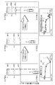
- FIG. 2 is an example of a candidate area (support area) according to the present embodiment.
- FIG. 3 is an explanatory diagram of a deceleration pattern according to the present embodiment.
- FIG. 4 is an explanatory diagram of a running pattern according to the present embodiment.
- FIG. 5 is an explanatory diagram of deceleration prediction according to the present embodiment.
- FIG. 6 is an example of the pre-approach action distribution of the accelerator pattern flapping with the deceleration start position distribution of each traveling pattern according to the present embodiment.
- the vehicle information processing system 1 learns candidate areas for setting support candidate areas, learns deceleration actions for each candidate area and extracts deceleration prediction information, and predicts deceleration prediction information for each support area (read ahead). Information) is output, and eco-support is performed using the deceleration prediction information.
- the vehicle information processing system 1 includes a road-vehicle communication device 2, a navigation system 3, a CAN [Controller Area Network] 4, an ITSECU [ElectronicElectroControl Unit] 5, and an HV [Hybridbrvehicle] ECU 6.
- information for each vehicle is stored in a database.
- a means for recognizing a driver may be provided, and information may be stored in the database for each recognized driver. If a driver who drives the vehicle is specified, information on the driver is stored in the database.
- a method for specifying the driver for example, a method for specifying the driver from the behavior of the vehicle, the travel route, or the like is used.
- the road-to-vehicle communication device 2 is a device for performing road-to-vehicle communication with infrastructure beacons and the like.
- the road-to-vehicle communication device 2 receives information from the infrastructure and transmits the received information to the ITSECU 5.
- the information required by the ITSECU 5 includes, for example, road alignment information up to the serviced intersection, information on the intersection (for example, intersection shape information and position information, stop line information), signal cycle, etc. There is information.
- Navigation system 3 is a system that detects the current position of the vehicle and provides route guidance to the destination.
- the navigation system 3 transmits the current position information to the ITSECU 5 and the HVECU 6 when the current position of the vehicle is detected at regular intervals based on signals received by a GPS [Global Positioning System] device.
- the map information required by the ITSECU 5 among the data stored in the map database is transmitted to the ITSECU 5.
- the information required by the ITSECU 5 is, for example, position information of a place where the vehicle stop is stipulated by law, and position information such as temporary stop, railroad crossing, and traffic lights.
- a configuration may be provided that includes a GPS device in order to acquire the current position of the vehicle.
- CAN4 is a LAN in the vehicle and is used for transmission / reception of information in the vehicle.
- information required by the ITSECU 5 includes, for example, accelerator operation information, brake operation information, vehicle speed information, and acceleration / deceleration information.
- the ITSECU 5 has a CAN 4 communication interface.
- the ITSECU 5 is an electronic control unit including a CPU [Central Processing Unit], ROM [Read Only Memory], RAM [Random Access Memory], and implements various functions of the intelligent transportation system.
- a CPU Central Processing Unit
- ROM Read Only Memory
- RAM Random Access Memory
- each process in the ITSECU 5 corresponds to an operation pattern setting unit and support information determination unit described in the claims
- the database 5b corresponds to a database described in the claims.
- a frequent deceleration operation section is extracted as a candidate area in the travel route of the vehicle (and thus the driver of the vehicle).
- One method is to select candidate areas based on the position where the vehicle is predicted to decelerate and stop on the route of the vehicle (for example, temporary stop, traffic light (red light), crossing, etc., which are determined by law). This is the extraction method.
- Another method is that the driver's pedal operation information and the vehicle position information when the driver is driving the vehicle are linked and stored, and the vehicle driver actually uses the stored information based on the stored information. This is a method of extracting a section where deceleration operations occur frequently as a candidate area.
- the ITS ECU 5 receives from the navigation system 3 (map database) map information relating to the road on which the vehicle is running (particularly, information on the position where the vehicle such as temporary stop, railroad crossing, traffic lights, etc. is predicted to stop). Then, every time the current position information is received from the navigation system 3, the ITSECU 5 passes the position where the vehicle is predicted to stop (in such a position, it is predicted that deceleration operations will frequently occur in the previous section). Determine whether or not. When the vehicle passes a position where the vehicle is predicted to stop, the ITSECU 5 sets a candidate area based on the position information. Note that the position where the vehicle is predicted to stop may include a position registered at a destination or a point in the navigation system 3 such as a home or office.
- the ITSECU 5 stores the accelerator operation information and brake operation information from the CAN 4 and the current position information from the navigation system 3 in the database 5a in association with each other at a certain time or a certain traveling distance while the vehicle is traveling.
- the ITSECU 5 extracts a deceleration operation based on the accelerator operation information and the brake operation information accumulated in the database 5a.
- the deceleration operation is an operation performed in the order of accelerator OFF, brake ON / OFF (repeatable), and accelerator ON.
- the ITSECU 5 counts up the number of passages that have passed through the same route, and when a deceleration operation is extracted in the same section, counts up the number of deceleration operations, and divides the number of deceleration operations by the number of passages to reduce the deceleration operation rate. Is calculated. Further, in the ITSECU 5, a section where the number of times of passage is a predetermined number or more (for example, 5 times, 10 times or more) and the deceleration operation rate is a threshold value or more (for example, 80% or 90% or more) is set as a candidate area. Other methods may be used as a method for determining a section where deceleration operations frequently occur.
- the ITSECU 5 When setting the candidate area, the ITSECU 5 sets an area that includes all lanes in the vehicle traveling direction as the width direction as the candidate area and has a predetermined distance as the length direction.
- the predetermined distance is a distance that sufficiently includes the driver's deceleration operation for stopping. For example, as shown in FIG. 2, in the case of an intersection with a temporary stop line L, from a central position in the intersection in front of the temporary stop line L to a predetermined position (position several hundred meters before) of the temporary stop line L Is set as the candidate area CA.
- the length of this section is a distance that can sufficiently extract the deceleration action when stopping.
- a range suitable for each vehicle may be set by learning and utilizing the travel distance during the driver's deceleration operation for each vehicle.
- deceleration learning In deceleration action learning, each time passing through a candidate area, various types of information are accumulated, an effective deceleration operation (approach action) within the candidate area is extracted from the accumulated information, and an effective deceleration operation is extracted. A candidate area with a high frequency is identified as a support area, and deceleration prediction information in the support area is generated.
- deceleration prediction information In deceleration behavior learning, the driving operation before the extracted approach behavior (pre-approach behavior) is extracted, and deceleration prediction information is provided for each driving pattern corresponding to the pre-approach behavior. Generate and set reliability for each running pattern.
- the deceleration prediction information includes the deceleration start position (position where the accelerator is turned off) AF, brake start position (position where the brake is turned on) BN, stop position (brake is turned off) for each support area AA. Position) BF.
- the deceleration prediction information is generated for each support area and is generated for each travel pattern of each support area.
- the deceleration pattern is a pattern that shows the transition of pedal operation that can respond to a wide variety of driving behaviors, focusing on pedal operations that are essential for carrying out deceleration behaviors, and accompanied by a brake operation triggered by an accelerator OFF operation It is a pattern of deceleration action.
- FIG. 3 shows an example of the deceleration pattern.
- the deceleration pattern indicated by reference numeral P1 is a basic operation deceleration pattern
- the deceleration pattern indicated by reference numeral P2 is a disturbance (for example, a stopped vehicle) before the deceleration target is decelerated.
- (Avoidance, interruption) is a deceleration pattern with deceleration
- the deceleration pattern indicated by reference symbol P3 is a two-step stop deceleration pattern
- the deceleration pattern indicated by symbol P4 is a deceleration pattern at the pumping brake, and is indicated by reference symbol P5.
- the pattern is a deceleration pattern when a creep operation is performed.
- this creep operation is an operation in which the driver gradually changes the stop position by repeatedly turning the brake on / off after the vehicle stops.
- the horizontal axis is the vehicle position (travel distance) L
- the vertical axis is the vehicle speed V.
- a white triangle in the figure indicates an accelerator OFF operation
- a white circle indicates an accelerator ON operation
- a black triangle indicates a brake OFF operation
- a black circle indicates a brake ON operation.
- the section (b) shown in the figure is the section for the approach action to the deceleration target
- the section (a) is the section for the pre-approach action
- (c) is the section for the post-approach action.
- the deceleration action in the approach action section in (b) is a deceleration stop action to the deceleration target of the vehicle (driver).
- the driving pattern is a pattern showing a transition of pedal operation that can cope with various driving actions in the support area including the deceleration stop action (approach action) to the deceleration target in the approach action section described above (in the claims) Equivalent to the operation pattern).
- the driving pattern is set by focusing on the pre-approach action in consideration of the driver's driving habit and the influence of disturbance (the driver's pedal operation factor). By using such various driving patterns, it is possible to distinguish whether the approach behavior is due to the driver's driving habit or the influence of disturbance, and to provide more accurate deceleration prediction information . Each travel pattern is given reliability.
- FIG. 4 shows an example of the traveling pattern.
- the traveling pattern indicated by reference numeral M1 is a basic pattern
- the traveling pattern indicated by reference numeral M2 is an accelerator pattern
- the traveling pattern indicated by reference numeral M3 is decelerated due to disturbance. This is a pattern, and is a deceleration pattern caused by an accelerator and disturbance in which the running pattern indicated by reference numeral M4 flutters.
- the basic pattern M1 is a pattern having no action before the approach action A1.
- the flapping accelerator pattern M2 is a pattern in which the pre-approach action F2 of the accelerator operation ON / OFF operation is present before the approach action A2. In the example shown in FIG. 4, there is also a two-step stop deceleration operation after the approach action A2.
- the deceleration pattern M3 due to disturbance is a pattern in which the pre-approach action F3 of the deceleration operation due to disturbance is present before the approach action A3.
- the fluttering accelerator & disturbance deceleration pattern M4 is a pattern in which the accelerator operation ON / OFF pre-approach action F41 and the deceleration operation pre-approach action F42 due to disturbance are present before the approach action A4. Since these four driving patterns are data for generating deceleration prediction information for each driving pattern, they are necessary as learning data, and the data is stored.
- the driving pattern that does not include the deceleration stop action (approach action) to the deceleration target in the approach action section is not data for generating deceleration prediction information, and is not necessary as learning data. Is destroyed. This is the data of the “discarded area” shown in FIG. 4 and has a running pattern that does not include the deceleration stop action to the deceleration target mainly due to the influence of disturbance.
- the reliability is an index for determining a running pattern that is a base when generating deceleration prediction information that is output when the vehicle enters the support area.
- the reliability is an index for determining a running pattern that is a base when generating deceleration prediction information that is output when the vehicle enters the support area.
- four ranks of A rank, B rank, C rank, and D rank are prepared in descending order of reliability, and A rank is the base. It becomes a running pattern.
- the vehicle when the vehicle enters the support area, it outputs deceleration prediction information of the driving pattern of rank A, and the pre-approach action check section (from the entry point of the support area)
- the pre-approach action is checked based on the pedal operation in the A rank travel pattern to the deceleration start position
- the travel pattern is recognized, and the travel pattern other than the A rank travel pattern is recognized. Change to the deceleration prediction information of the running pattern and output.
- the reliability is set in two steps.
- the deceleration start positions of the approach behaviors of the respective travel patterns are compared, and high ranks are given in the order of starting the deceleration approach earliest from the area approach in the four travel patterns.
- FIG. 6 shows an example of the deceleration start position distribution of each travel pattern in a certain support area.
- the distribution indicated by reference sign D1 is the basic pattern deceleration start position distribution
- the distribution indicated by reference sign D2 is a flickering accelerator pattern.
- the distribution indicated by reference sign D3 is the deceleration start position distribution of the deceleration pattern due to disturbance
- the distribution indicated by reference sign D4 is the deceleration start position distribution of the deceleration pattern due to fluttering and disturbance.
- the A rank is set for the basic pattern
- the B rank for the flapping accelerator pattern the C rank for the deceleration pattern due to disturbance
- the D rank for the flapping accelerator & disturbance deceleration pattern By the way, as a result of verification in various areas, there is knowledge that the basic pattern starts deceleration action the earliest.
- the basic pattern is A rank
- the fluttering accelerator pattern is B rank. Therefore, the basic pattern deceleration prediction information is output when the support area is entered. Then, as shown in FIG. 6A, when the pre-approach action F21 of the fluttering accelerator can be detected in the pre-approach action check section, the deceleration prediction information of the fluttering accelerator pattern can be output.
- FIG. 6A when the pre-approach action F21 of the fluttering accelerator can be detected in the pre-approach action check section, the deceleration prediction information of the fluttering accelerator pattern can be output.
- the deceleration prediction information of the flapping accelerator pattern is output regardless of the flapping accelerator pattern. Can not. In such a case, the accuracy of the deceleration prediction information decreases.
- a rank and B rank are compared to solve the above-mentioned problems.
- the rank A deceleration start position distribution and the rank B pre-approach action distribution are compared. If the rank A deceleration start position distribution is closer to the stop position than the rank B pre-approach action distribution, The rank is maintained, and when the pre-approach action distribution of the B rank is closer to the stop position than the deceleration start position distribution of the A rank, the rank is changed according to the ratio of the execution frequency of the basic pattern. This specific change process will be described later in detail.
- the ITSECU 5 determines whether or not the vehicle has entered the candidate area every time the current position information is received from the navigation system 3 while the vehicle is traveling. If it is determined that the vehicle has entered the candidate area, the ITSECU 5 performs accelerator operation information and brake operation information from the CAN 4 and vehicle state information (for example, vehicle speed information, acceleration / deceleration information), navigation, and the like at regular time intervals or constant travel distances.
- vehicle state information for example, vehicle speed information, acceleration / deceleration information
- navigation and the like at regular time intervals or constant travel distances.
- the current position information from the system 3 is linked and stored in the database 5b.
- the ITSECU 5 determines whether or not the vehicle has left the candidate area every time the current position information is received from the navigation system 3 while the vehicle is traveling.
- the ITSECU 5 finishes accumulating the information in the database 5b and increments the number of times of passage for the candidate area that has passed by one. As the data stored in the database 5b, only information when the accelerator pedal / brake pedal ON / OFF is detected may be stored.
- the ITSECU 5 sorts the deceleration operation and the acceleration operation based on the data accumulated this time for the candidate area, and extracts the deceleration operation.
- the deceleration operation is an operation performed in the order of accelerator OFF, brake ON / OFF (repeatable), and accelerator ON.
- the acceleration operation is an operation performed in the order of accelerator OFF and accelerator ON (repeatable).
- the ITSECU 5 determines a corresponding deceleration pattern from the prepared deceleration patterns based on the deceleration operation, and the deceleration operation in the candidate area is an approach action to the deceleration target or before and after the approach. And only the approach action is extracted from the deceleration operations in the candidate area. In this way, the ITSECU 5 determines whether or not the vehicle has decelerated and stopped by the approach action (deceleration operation) within the candidate area. If there is no such action, the number of stops is not counted, and further processing thereafter is stopped.
- the deceleration operation at the approach is a deceleration from high speed to low speed (especially stop)
- the deceleration operation before the approach is a deceleration from high speed to high speed
- the deceleration operation is a deceleration from low speed to low speed. Therefore, the deceleration operation in the case of high speed to low speed (stop) is extracted as an approach action to the deceleration target.
- the deceleration operation S11 is an approach action, and the deceleration operation S11 is extracted.
- the deceleration pattern P2 with deceleration due to disturbance the deceleration operation S21 is a pre-approach action, the deceleration operation S22 is an approach action, and the deceleration operation S22 is extracted.
- the deceleration operation S31 is an approach action
- the deceleration operation S32 is an action after the approach
- the deceleration operation S31 is extracted.
- the deceleration operation S41 is an approach action, and the deceleration operation S41 is extracted.
- the deceleration operation S51 is an approach action. However, in this case, since the creep operation after stopping is extracted together, it is necessary to appropriately remove the creep portion.
- the ITSECU 5 determines whether or not the creep operation is performed in the approach action. In this determination, attention is paid to the vehicle speed when the brake is OFF in the operation within the approach, and when there are a plurality of brake OFF operations continuously at the low vehicle speed, it is determined that there is creep. If there is a creep operation, the vehicle stops and the stop position is changed by the driver's brake ON / OFF operation after the brake is turned off. Therefore, in order to accurately determine the vehicle stop position, the presence / absence of the creep operation is determined. Yes.
- the ITSECU 5 sorts the pre-approach action from the travel patterns for which the approach behavior can be extracted, and recognizes which of the four travel patterns is the travel pattern. First, it is determined whether or not there is a pre-approach action based on driving operation information in the area, and when there is no pre-approach action, it is determined as a basic pattern. If it is not a basic pattern, it is determined whether there is any operation of flapping accelerator operation, deceleration operation due to disturbance, flapping acceleration operation, or deceleration operation due to disturbance based on driving operation information before approach action in the area.
- the traveling pattern is an accelerator pattern that flutters, a deceleration pattern due to disturbance, or a flickering accelerator & deceleration pattern due to disturbance.
- the recognition result is used.
- the ITS ECU 5 identifies the deceleration start position from the position information when the accelerator is turned off based on the deceleration operation in the approach action, and determines the brake start position from the position information when the brake is turned on.
- the stop position is specified from the position information when the brake is turned off.
- the brake ON operation when the brake ON / OFF is repeated, the brake ON operation immediately after the accelerator OFF operation is extracted.
- the brake OFF operation when the brake ON / OFF is repeated, the last brake OFF operation is extracted. However, if there is a creep operation, the first brake-off operation that starts the creep operation is extracted.
- the position at the accelerator OFF operation AF1 is the deceleration start position
- the position at the brake ON operation BN1 is the brake start position
- the position at the brake OFF operation BF1 is the stop position.
- the position at the accelerator OFF operation AF3 is the deceleration start position
- the position at the brake ON operation BN3 is the brake start position
- the position at the brake OFF operation BF3 is the stop position.
- the position at the accelerator OFF operation AF4 is the deceleration start position
- the position at the brake ON operation BN4 is the brake start position
- the position at the brake OFF operation BF4 is the stop position.
- the position at the time of the accelerator OFF operation AF5 is the deceleration start position
- the position at the time of the brake ON operation BN5 is the brake start position
- the position at the time of the brake OFF operation BF5 is the stop position.
- the ITSECU 5 determines that there has been a deceleration stop action in the candidate area, the number of stops for that candidate area is incremented by one. Further, the ITSECU 5 divides the number of stops for the candidate area by the number of passes (total number of passes) to calculate a stop rate.
- the number of passages for the candidate area is a predetermined number or more (for example, 5 times, 10 times or more), and the stop rate (corresponding to the stop frequency) is a threshold value or more (for example, 80%, 90% or more).
- the candidate area is specified as the support area.
- the ITSECU 5 updates support area registration information for the support area.
- the support area registration information is deceleration prediction information for the support area, and is deceleration start position information, brake start position information, and stop position information for each support area (a stop rate (stop frequency) may also be included).
- This deceleration start position is the usual deceleration start position when the vehicle (driver) stops with respect to the deceleration target, and this brake start position is the usual brake start position where the driver of the vehicle starts the brake operation,
- This stop position is the usual stop position of the vehicle (driver).
- Assistance area registration information includes, for each support area, information including all travel patterns in the support area and information on four travel patterns. Therefore, every time deceleration action learning is performed for a certain area, the support area registration information as the entire area is updated, and the support area registration information of the travel pattern recognized by the learning at that time is updated.
- the ITSECU 5 stores the updated support area registration information in the database 5b.
- the ITSECU 5 sets (updates) the reliability for the four travel patterns.
- the ITSECU 5 stores the reliability of each changed traveling pattern in the database 5b.
- the ITSECU 5 compares the positions of the deceleration start position distributions of the four travel patterns using the deceleration start position information of the approach behavior of each travel pattern stored in the database 5b, and starts deceleration.
- a high rank is set as the reliability in the order of the position distribution closer to the area entry point.
- rank A is set for the basic pattern, and the deceleration start position distribution is compared for the other three traveling patterns, and the reliability Set. Therefore, in the first step, the basic pattern is set to A rank.
- the deceleration start position information of the approach behavior of the A rank traveling pattern (basic pattern traveling pattern) and the position information of the driving operation of the pre-approach behavior of the B rank traveling pattern accumulated in the database 5b are stored.
- the position of the deceleration start position distribution of the driving pattern of A rank and the pre-approach action distribution of the driving pattern of B rank are compared.
- the ITSECU 5 maintains the reliability rank according to the position comparison of the deceleration start position distribution. .
- the ITSECU 5 uses the number of stops of each driving pattern stored in the database 5b.
- the rank of reliability is set based on the ratio of the execution frequency with the basic pattern (when the conditions shown below are satisfied, the A rank and the B rank are switched).
- a traveling pattern having a high frequency of implementation in each area is usually an operation pattern often performed by the driver in that area, and therefore, there is a high possibility that the driving pattern is a driver's driving operation.
- the deceleration traveling pattern due to disturbance is affected by disturbance, so a high ratio of 2.0 times was used as a condition.
- the average position of the distribution is calculated and compared with the average position, or compared using the position farthest from the stop position in the distribution. To do.
- deceleration prediction when entering the support area, the deceleration prediction information of the rank A travel pattern is output.
- the traveling pattern is recognized in the pre-approach action check section, and when the recognized traveling pattern is not rank A, the deceleration prediction information of the recognized traveling pattern is output.
- the ITSECU 5 when it is determined that the candidate area has been entered by the above-described processing and the candidate area is specified as the support area, the travel pattern of rank A of this support area accumulated in the database 5b. Is output to the HVEUC 6. Then, every time the ITSECU 5 receives the current position information from the navigation system 3 after entering the support area, the ITSECU 5 determines whether or not the deceleration start position of the rank A travel pattern has been reached.
- the ITSECU 5 While it is determined that the deceleration start position of the driving pattern of rank A has not been reached (that is, the pre-approach action check section), the ITSECU 5 performs the accelerator operation in the pre-approach action check section accumulated in the database 5b. Using the information and the brake operation information, any one of the four traveling patterns is recognized.
- the travel pattern is recognized by determining whether there is a pre-approach action described in the above-mentioned deceleration action learning, and if there is a pre-approach action, which of the three travel patterns is the pre-approach action. To do. If the recognized traveling pattern is not the A-rank traveling pattern, the ITSECU 5 outputs to the HVEUC 6 the deceleration prediction information of the recognized traveling area in the support area stored in the database 5b.
- rank A is the basic pattern
- the basic pattern deceleration prediction information Y1 (deceleration start position AF1, brake start position BN1, stop position BF1) is output.
- the flickering acceleration pattern deceleration prediction information Y2 (deceleration start position AF2, brake start position BN2, stop position BF2) is obtained. Output.
- each position AF2, BN2, BF2 of the fluttering accelerator deceleration prediction information Y2 is closer to the temporary stop line L than each position AF1, BN1, BF1) of the basic pattern deceleration prediction information Y1, the positions AF2, BN2, BF2 are By using this, it is possible to provide more accurate eco-support that matches the current driving pattern of the driver.
- the HVECU 6 is an electronic control unit including a CPU, a ROM, a RAM, and the like, and controls an engine and a motor (inverter) that are power sources of the hybrid vehicle, a brake that is a braking source, and the like.
- a motor inverter
- the eco support function using the deceleration prediction information corresponding to the travel pattern from the ITSECU 5 among the functions in the HVECU 6 will be described.
- the HVECU 6 determines whether or not the vehicle has entered the support area every time the current position information is received from the navigation system 3 while the vehicle is traveling. When it is determined that the vehicle has entered the support area, the HVECU 6 provides information for prompting the driver to perform an accelerator OFF operation earlier than usual at a position before the deceleration start position based on the deceleration start position of the deceleration prediction information. In this information provision, for example, a message such as “If the accelerator is turned off earlier than usual, fuel consumption can be suppressed” is displayed on the screen, or a voice is output.
- the HVECU 6 increases the regenerative brake amount (for example, increases the deceleration) based on the stop position of the deceleration prediction information, so that the motor (inverter) And control the brake.
- the eco support using the deceleration prediction information shown here is an example, and the eco support may be performed by another method using the deceleration prediction information.
- acceleration / deceleration control is performed by control on the vehicle side. Therefore, based on the usual deceleration / stopping behavior of the vehicle (driver) at the usual deceleration / stop location of the vehicle (driver).
- acceleration / deceleration control is performed by control on the vehicle side. Therefore, based on the usual deceleration / stopping behavior of the vehicle (driver) at the usual deceleration / stop location of the vehicle (driver).
- By controlling the engine, motor, and brake on the vehicle side it is preferable to accelerate the accelerator off based on the deceleration prediction information, increase the regenerative brake amount, and stop the engine.
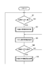
- FIG. 7 is a flowchart showing a flow of main processing in the ITSECU according to the present embodiment.
- FIG. 8 is a flowchart showing the flow of prefetch information provision processing in the ITSECU according to the present embodiment.
- FIG. 9 is a flowchart showing a flow of behavior characteristic information update processing in the ITSECU according to the present embodiment. In the ITSECU 5 or the like, each process is started when the ignition switch is turned on.
- the road-to-vehicle communication device 2 receives road alignment information from the infrastructure to the intersection to be serviced, information on the intersection, signal cycle information, and the like. Information is transmitted to the ITSECU 5.
- the navigation system 3 transmits the current position information and map information around the current position to the ITSECU 5 every time the current position is detected based on the GPS signal or the like. Further, the ITSECU 5 acquires pedal operation information, vehicle speed information, and the like from the CAN 4.
- the ITS ECU 5 determines whether or not the vehicle has passed a position where the vehicle is predicted to stop based on the map information (section where deceleration operations are expected to occur frequently) every time the vehicle receives the current position information while traveling. When the vehicle passes a position where the vehicle is predicted to stop, a candidate area is set based on the position information. Alternatively, the ITS ECU 5 accumulates the pedal operation information and the current position information in the database 5a in association with the pedal operation information at every certain time or every certain traveling distance during traveling of the vehicle. Then, the ITSECU 5 extracts a deceleration operation from the pedal operation information stored in the database 5a, discriminates a section with many deceleration operations in the same section, and sets the section as a candidate area.
- the ITSECU 5 determines whether or not the vehicle has entered the candidate area based on the current position information every time the current position information is received while the vehicle is traveling (S1). If it is determined in S1 that the vehicle has not entered the candidate area, the ITSECU 5 waits until the next current position information is received, and determines again whether or not the vehicle has entered the candidate area (S1). If it is determined in S1 that the candidate area has been entered, the ITSECU 5 performs prefetching information provision processing if the candidate area is identified as a support area (S2).
- the ITSECU 5 uses the assistance area registration information stored in the database 5b when entering the assistance area, and uses the assistance area registration information stored in the database 5b to obtain the deceleration prediction information of the driving pattern with the reliability A rank. Output to the HVECU 6 (S20).
- the ITSECU 5 obtains pedal operation information and vehicle behavior information (for example, vehicle speed information) from the CAN 4 every time the current position information is received (or at every fixed time or every time the pedal ON / OFF is detected). Then, the pedal operation information, the current position information, and the vehicle behavior information are associated with each other and stored in the database 5b as data of the candidate area that is currently approaching (S21). Then, the ITSECU 5 sorts the pre-approach action based on the information on the pre-approach action check section stored in the database 5b, and recognizes the current driving pattern of the driver in the support area being entered (S22). If the recognized traveling pattern is different from the traveling pattern with the reliability A rank, the ITSECU 5 uses the assistance area registration information stored in the database 5b to obtain the deceleration prediction information of the recognized traveling pattern. It outputs to the HVECU 6 (S23).
- vehicle behavior information for example, vehicle speed information
- the ITSECU 5 determines whether or not the deceleration start position of the travel pattern with the reliability A rank has been reached based on the current position information (S24). If it is determined in S24 that the deceleration start position has not been reached (within the pre-approach action check section), the ITSECU 5 returns to the process of S21. If it is determined in S24 that the deceleration start position has been reached (outside the pre-approach action check section), the ITSECU 5 ends the prefetch information providing process.
- the ITSECU 5 After completing the prefetch information providing process, the ITSECU 5 acquires pedal operation information and the like by the same process as S21 and stores it in the database 5b (S3). Then, the ITSECU 5 determines whether or not the candidate area has been exited based on the current position information (S4). If it is determined in S4 that the candidate area has not been exited, the ITSECU 5 returns to the process of S3. If it is determined in S4 that the candidate area has been exited, the ITSECU 5 proceeds to a behavior characteristic information update process (S5).
- S5 behavior characteristic information update process
- the ITSECU 5 increments the number of times of passage for the candidate area by 1 (S50).
- the ITSECU 5 sorts the deceleration operation and the acceleration operation based on the pedal operation information accumulated this time for the candidate area in the database 5b, and extracts the deceleration operation (S51). If the deceleration operation can be extracted in S51, the ITSECU 5 determines the corresponding deceleration pattern from the deceleration patterns as the first filter and determines whether the deceleration operation is an approach action to the deceleration target or a deceleration action before and after the approach. Is determined (S52).
- the ITSECU 5 determines whether or not the vehicle has been stopped by the deceleration operation of the approach action within the candidate area. When only the approach action is extracted from the deceleration operations in the candidate area, the ITSECU 5 determines the presence or absence of the creep operation in the approach action as the second filter (S52). In the case of an approach action without a creep operation, the ITSECU 5 specifies the deceleration start position from the position information when the accelerator is turned off based on the deceleration action in the approach action, and the brake is first turned on after the accelerator is turned off. The brake start position is specified from the position information at the time, and the stop position is specified from the position information when the brake is finally turned off.
- the ITSECU 5 specifies the deceleration start position and the brake start position in the same manner as described above, and determines the stop position from the position information when the brake that starts during the creep operation is first turned OFF. Specify the stop position.
- the ITSECU 5 When it is determined that there has been a deceleration stop action (when the filter has been passed through the filter inspection in S52), the ITSECU 5 adds the number of stops for that candidate area (1 count up) (S53). Further, the ITS ECU 5 updates the stop rate from the number of stops and the number of passes for the candidate area.
- the ITSECU 5 sorts the pre-approach action based on the information accumulated this time for the candidate area in the database 5b, and recognizes the current driving pattern of the driver (S54). If the traveling pattern can be recognized in the process of S22, the recognition result may be used.
- the ITSECU 5 compares the positions of the deceleration start position distributions of the four travel patterns based on the deceleration start position information for the four travel patterns accumulated so far for the candidate area in the database 5b, and starts deceleration. Highest rank travel patterns are set as reliability in the order of position distribution closer to the area entry point (S55).
- the deceleration start position information and the execution frequency information regarding the A rank traveling pattern accumulated up to the present in the database 5b for the candidate area, and the operation position of the pre-approach action regarding the B rank traveling pattern Based on the information and the execution frequency information, the position of the deceleration start position distribution of the driving pattern of the A rank and the pre-approach action distribution of the driving pattern of the B rank are compared. If it is closer to the stop position than the deceleration start position distribution of the rank travel pattern, the A rank and the B rank are switched only when the above condition is satisfied based on the ratio of the execution frequency to the basic pattern (S55).
- the ITSECU 5 identifies the candidate area as a support area when the number of times of passage for the candidate area is a predetermined number or more and the stop rate is a threshold or more.
- the ITSECU 5 includes support area registration information (deceleration prediction information, deceleration start position information, brake start position information, stop position information, stop frequency information, etc. for each support area. ) And the support area registration information for the current driving pattern are updated, and the updated information is stored in the database 5b (S56). Further, when the reliability of each traveling pattern is updated by the above processing, the ITSECU 5 accumulates the updated reliability of each traveling pattern in the database 5b (S56). Then, the ITSECU 5 ends the behavior characteristic information update process and returns to the process of S1.
- the HVECU 6 When deceleration prediction information is input from the ITSECU 5, the HVECU 6 based on the usual deceleration start position, brake start position, and stop position of the vehicle (and thus the driver of the vehicle) in the current travel pattern in the support area, Provide information and control vehicles for the purpose of eco-support.
- each of the four travel patterns and the deceleration support information of each travel pattern are linked and accumulated in the database 5b for each support area.
- the traveling pattern when entering, and outputting the deceleration support information according to the recognized traveling pattern, it is possible to assist the driver using the highly accurate deceleration prediction information according to the traveling pattern. (Prediction accuracy used for support is improved), and support suitable for the driver can be performed with high accuracy.
- the driver can receive assistance without being bothered or discomforted by the assistance.
- by outputting the deceleration support information corresponding to the travel pattern it is possible to provide eco support that matches the driver's travel pattern at that time.
- the vehicle information processing system 1 by preparing four driving patterns according to the influence of driver's driving habits and disturbances, it is possible to enter each area from the four driving patterns.
- the traveling pattern can be easily and accurately recognized based on the driving operation information of the driver.
- the deceleration support information to be output based on the reliability can be determined easily and with high accuracy.
- the reliability is highly accurate for each travel pattern. It can be set, and the deceleration support information of the running pattern that starts the deceleration approach earliest can be output.
- each of the A rank and B rank travel patterns can be switched between the A rank and the B rank based on the ratio of the execution frequency to the basic pattern.
- the vehicle information processing system 1 when different driving patterns are recognized in the pre-approach action check section while outputting the deceleration prediction information of the driving pattern of rank A at the time of entering the support area, By outputting the deceleration prediction information, highly accurate deceleration prediction information can be output at an early stage, and can be changed to more accurate deceleration prediction information.
- the vehicle is provided with a database and each vehicle learns, but a center that provides various services to the vehicle may include a database and each center may perform each learning.
- a center that provides various services to the vehicle may include a database and each center may perform each learning.
- the memory capacity and processing load in each vehicle can be reduced.
- the center includes a database
- wireless communication can be performed between the vehicle and the center, and the vehicle transmits each piece of information stored in the database to the center and receives support area registration information and the like from the center.
- the center database stores data for every vehicle (driver) to be supported.
- the center may be provided with a database, and each learning may be performed by each vehicle. Even in this case, the memory capacity in the vehicle can be reduced.
- the present invention is applied to support for deceleration stop, but can also be applied to support for start acceleration.
- the start acceleration the candidate area learning and the start acceleration action learning can be performed by the same method by using various start acceleration patterns and travel patterns.
- it can also be applied to other support.
- the support area is identified from the candidate areas based on the stop frequency, but another method may be used to identify the support area.
- the reliability setting method is set for each traveling pattern, and the deceleration prediction information to be output is determined based on the reliability.
- the deceleration prediction information is set without setting the reliability to the traveling pattern. It is good also as a structure to determine.
- the action start position before stop is set as the deceleration start position and the travel pattern is recognized based on the section to the deceleration start position.
- the action start position before stop includes the brake start position and the stop It may be a position.
- the present invention sets a driver's operation pattern when entering a support area and determines support information according to the operation pattern, thereby providing support to the driver using highly accurate support information according to the operation pattern. It is possible to provide support suitable for the driver with high accuracy.
- SYMBOLS 1 Information processing system for vehicles, 2 ... Road-to-vehicle communication apparatus, 3 ... Navigation system, 4 ... CAN, 5 ... ITSECU, 5a, 5b ... Database, 6 ... HVECU.
Landscapes
- Engineering & Computer Science (AREA)
- Transportation (AREA)
- Mechanical Engineering (AREA)
- Automation & Control Theory (AREA)
- Combustion & Propulsion (AREA)
- Chemical & Material Sciences (AREA)
- Power Engineering (AREA)
- Human Computer Interaction (AREA)
- Physics & Mathematics (AREA)
- Mathematical Physics (AREA)
- Traffic Control Systems (AREA)
- Control Of Driving Devices And Active Controlling Of Vehicle (AREA)
- Navigation (AREA)
Abstract
Description
Claims (10)
- 特定された支援エリアにおいてドライバに対して支援を行うための車両用情報処理システムであって、
前記支援エリア進入時のドライバの運転操作情報に基づいて該支援エリアにおける操作パターンを設定する操作パターン設定手段と、
前記操作パターン設定手段で設定した支援エリアにおける操作パターンに応じて該支援エリアにおいてドライバに対して支援を行うための支援情報を決定する支援情報決定手段と、
を備えることを特徴とする車両用情報処理システム。 - 前記支援エリアにおける操作パターンは、操作要因に応じて設けられ、
前記操作パターン設定手段は、支援エリア進入時から停止前行動開始位置までのドライバの運転操作情報に基づいて該支援エリアにおける操作パターンを設定することを特徴とする請求項1に記載の車両用情報処理システム。 - 前記支援情報決定手段は、前記操作パターン設定手段で設定した支援エリアにおける操作パターンに変更がある場合には該変更された操作パターンに応じて支援情報を変更することを特徴とする請求項1又は請求項2に記載の車両用情報処理システム。
- 前記支援エリア進入位置からの停止前行動開始位置に応じて操作パターン毎に信頼度が設定され、
前記支援情報決定手段は、操作パターン毎の信頼度に基づいて支援情報を決定することを特徴とする請求項1~請求項3のいずれか1項に記載の車両用情報処理システム。 - 前記信頼度は、前記支援エリアにおける前記停止前行動開始位置が前記支援エリア進入位置に近い操作パターンほど高い信頼度が設定されることを特徴とする請求項4に記載の車両用情報処理システム。
- 前記信頼度は、前記支援エリアにおいて同じ操作パターンをドライバが実施した頻度に基づいて設定されることを特徴とする請求項4又は請求項5に記載の車両用情報処理システム。
- 前記信頼度は、実施頻度が低い操作パターンよりも実施頻度が高い操作パターンに高い信頼度が設定されることを特徴とする請求項6に記載の車両用情報処理システム。
- 特定された支援エリアにおいてドライバに対して支援を行うための車両用情報処理システムであって、
前記支援エリア毎に操作パターンと該操作パターンに応じたドライバに対して支援を行うための支援情報とを紐付けて記憶するデータースを備えることを特徴とする車両用情報処理システム。 - 前記データベースに記憶される操作パターン毎に信頼度が設定されることを特徴とする請求項8に記載の車両用情報処理システム。
- ドライバによる運転操作情報と車両の位置情報とを紐付けて記憶されており、該記憶されている情報に基づいて車両の停止が判断され、同じエリアでの停止頻度に基づいて支援エリアが特定されることを特徴とする請求項1~請求項9のいずれか1項に記載の車両用情報処理システム。
Priority Applications (5)
| Application Number | Priority Date | Filing Date | Title |
|---|---|---|---|
| JP2012552565A JP5605439B2 (ja) | 2011-01-12 | 2011-01-12 | 車両用情報処理システム |
| PCT/JP2011/050368 WO2012095964A1 (ja) | 2011-01-12 | 2011-01-12 | 車両用情報処理システム |
| CN201180064811.2A CN103298673B (zh) | 2011-01-12 | 2011-01-12 | 车辆用信息处理系统 |
| EP11855881.6A EP2665049B1 (en) | 2011-01-12 | 2011-01-12 | Vehicle information processing system |
| US13/976,752 US9457793B2 (en) | 2011-01-12 | 2011-01-12 | Vehicle information processing system |
Applications Claiming Priority (1)
| Application Number | Priority Date | Filing Date | Title |
|---|---|---|---|
| PCT/JP2011/050368 WO2012095964A1 (ja) | 2011-01-12 | 2011-01-12 | 車両用情報処理システム |
Publications (1)
| Publication Number | Publication Date |
|---|---|
| WO2012095964A1 true WO2012095964A1 (ja) | 2012-07-19 |
Family
ID=46506887
Family Applications (1)
| Application Number | Title | Priority Date | Filing Date |
|---|---|---|---|
| PCT/JP2011/050368 Ceased WO2012095964A1 (ja) | 2011-01-12 | 2011-01-12 | 車両用情報処理システム |
Country Status (5)
| Country | Link |
|---|---|
| US (1) | US9457793B2 (ja) |
| EP (1) | EP2665049B1 (ja) |
| JP (1) | JP5605439B2 (ja) |
| CN (1) | CN103298673B (ja) |
| WO (1) | WO2012095964A1 (ja) |
Cited By (5)
| Publication number | Priority date | Publication date | Assignee | Title |
|---|---|---|---|---|
| JP2014110677A (ja) * | 2012-11-30 | 2014-06-12 | Toyota Motor Corp | 運転支援装置 |
| WO2014202317A1 (de) * | 2013-06-18 | 2014-12-24 | Bayerische Motoren Werke Aktiengesellschaft | Verfahren zur bedarfsgerechten steuerung bzw. regelung des rekuperationsmoments einer im generatorbetrieb arbeitenden elektrischen maschine eines fahrzeugs |
| WO2015052027A1 (de) * | 2013-10-10 | 2015-04-16 | Continental Automotive Gmbh | Prädiktives verfahren zum betreiben eines fahrzeugs und dementsprechendes fahrerassistenzsystem für ein fahrzeug |
| US9360330B2 (en) | 2011-05-23 | 2016-06-07 | Toyota Jidosha Kabushiki Kaisha | Information processing system for vehicle |
| JPWO2017013750A1 (ja) * | 2015-07-21 | 2018-05-24 | 日産自動車株式会社 | 運転計画装置、走行支援装置、運転計画方法 |
Families Citing this family (11)
| Publication number | Priority date | Publication date | Assignee | Title |
|---|---|---|---|---|
| JP6001792B2 (ja) * | 2013-09-09 | 2016-10-05 | 三菱電機株式会社 | 運転支援装置および運転支援方法 |
| MX356836B (es) * | 2013-12-11 | 2018-06-15 | Intel Corp | Asistencia computarizada adaptada de preferencias de conducción individuales o conducción autónoma de vehículos. |
| US10053093B2 (en) | 2015-11-24 | 2018-08-21 | Bendix Commercial Vehicle Systems Llc | Method and system for controlling a cruise control system |
| US10189453B2 (en) | 2016-10-05 | 2019-01-29 | Toyota Motor Engineering & Manufacturing North America, Inc. | Coasting guidance timing and drive force adjustment |
| US9896106B1 (en) | 2016-10-24 | 2018-02-20 | Toyota Motor Engineering & Manufacturing North America, Inc. | Coasting distance determination for coasting assistance system |
| US9898928B1 (en) | 2016-10-25 | 2018-02-20 | Toyota Motor Engineering & Manufacturing North America, Inc. | Coasting guidance timing and learning based on approach lane |
| CN117022255A (zh) * | 2018-03-20 | 2023-11-10 | 御眼视觉技术有限公司 | 用于主车辆的自动驾驶系统、机器可读存储介质和装置 |
| JP6847885B2 (ja) * | 2018-03-20 | 2021-03-24 | 株式会社東芝 | 情報処理装置、情報処理方法及びプログラム |
| US11480117B2 (en) | 2018-12-17 | 2022-10-25 | Ford Global Technologies, Llc | Method and system for vehicle stop/start control |
| CN113395462B (zh) * | 2021-08-17 | 2021-12-14 | 腾讯科技(深圳)有限公司 | 导航视频生成、采集方法、装置、服务器、设备及介质 |
| DE102021213166B4 (de) * | 2021-11-23 | 2026-01-22 | Mercedes-Benz Group AG | Verfahren und Vorrichtung zur Steuerung eines automatisiert fahrenden Fahrzeugs |
Citations (5)
| Publication number | Priority date | Publication date | Assignee | Title |
|---|---|---|---|---|
| JP2008108247A (ja) * | 2007-10-09 | 2008-05-08 | Equos Research Co Ltd | 情報処理装置、及びハイブリッド車両 |
| JP2008213699A (ja) * | 2007-03-06 | 2008-09-18 | Toyota Motor Corp | 車両の運転制御装置および運転制御方法 |
| JP2009031837A (ja) * | 2007-07-24 | 2009-02-12 | Nissan Motor Co Ltd | 交差点通過支援装置および交差点通過支援方法 |
| JP2009053732A (ja) | 2007-08-23 | 2009-03-12 | Nissan Motor Co Ltd | 停止目標位置検出装置及び停止目標位置検出方法 |
| JP2009244167A (ja) | 2008-03-31 | 2009-10-22 | Mazda Motor Corp | 車両の運転支援方法及び運転支援装置 |
Family Cites Families (35)
| Publication number | Priority date | Publication date | Assignee | Title |
|---|---|---|---|---|
| US3872283A (en) | 1973-07-13 | 1975-03-18 | Cadre Corp | Vehicle identification method and apparatus |
| US5521823A (en) * | 1991-09-03 | 1996-05-28 | Mazda Motor Corporation | Learning control vehicle |
| US5661650A (en) | 1994-02-23 | 1997-08-26 | Honda Giken Kogyo Kabushiki Kaisha | System for controlling a vehicle relative to a judged shape of a travel road |
| US8019501B2 (en) | 1995-06-07 | 2011-09-13 | Automotive Technologies International, Inc. | Vehicle diagnostic and prognostic methods and systems |
| EP0863381B1 (en) | 1997-03-07 | 2004-06-02 | Pioneer Electronic Corporation | Navigation apparatus |
| US6252544B1 (en) | 1998-01-27 | 2001-06-26 | Steven M. Hoffberg | Mobile communication device |
| US6161072A (en) | 1999-01-21 | 2000-12-12 | Intel Corporation | Automatic cruise control |
| US6993421B2 (en) | 1999-07-30 | 2006-01-31 | Oshkosh Truck Corporation | Equipment service vehicle with network-assisted vehicle service and repair |
| SE516119C2 (sv) | 1999-08-27 | 2001-11-19 | Thoreb Ab | Metod och anordning för att assistera en förare av ett fordon |
| US6297732B2 (en) | 1999-09-08 | 2001-10-02 | Precision Navigation, Inc. | Radar/laser detection device with multi-sensing and reporting capability |
| US6847892B2 (en) | 2001-10-29 | 2005-01-25 | Digital Angel Corporation | System for localizing and sensing objects and providing alerts |
| DE20114418U1 (de) | 2001-08-31 | 2001-10-31 | Brose Fahrzeugteile GmbH & Co. Kommanditgesellschaft, 96450 Coburg | Steuersystem zum Steuern eines kraftfahrzeugseitigen Gerätes |
| JP4013712B2 (ja) * | 2002-09-13 | 2007-11-28 | 株式会社エクォス・リサーチ | 車両走行パターン作成装置、車両走行パターン作成方法及びエンジン始動停止装置 |
| US6631322B1 (en) | 2002-12-06 | 2003-10-07 | General Electric Co. | Method and apparatus for vehicle management |
| DE10315047A1 (de) * | 2003-04-02 | 2004-10-28 | Daimlerchrysler Ag | Vorrichtung zur positionsabhängigen Steuerung von Fahrzeugfunktionen |
| WO2005003885A2 (en) | 2003-07-07 | 2005-01-13 | Sensomatix Ltd. | Traffic information system |
| JP2005297817A (ja) | 2004-04-13 | 2005-10-27 | Fujitsu Ten Ltd | 運転支援装置 |
| JP2006058100A (ja) * | 2004-08-19 | 2006-03-02 | Fujitsu Ten Ltd | 運転支援装置、運転支援システムおよび運転支援方法 |
| JP2006072936A (ja) * | 2004-09-06 | 2006-03-16 | Sumitomo Electric Ind Ltd | 車両停止要求システム |
| JP2006347531A (ja) | 2005-05-16 | 2006-12-28 | Xanavi Informatics Corp | 車載端末装置、自動車の走行制御システム、及び自動車の制御方法 |
| JP4737519B2 (ja) | 2005-06-28 | 2011-08-03 | アイシン・エィ・ダブリュ株式会社 | 車両制御補助装置及び車両制御補助方法 |
| JP4816104B2 (ja) | 2006-01-26 | 2011-11-16 | トヨタ自動車株式会社 | 車両位置判定装置及び車両用駆動力制御装置 |
| US20070265759A1 (en) | 2006-05-09 | 2007-11-15 | David Salinas | Method and system for utilizing topographical awareness in an adaptive cruise control |
| JP4858039B2 (ja) | 2006-09-25 | 2012-01-18 | トヨタ自動車株式会社 | 車両制御装置 |
| WO2008136193A1 (ja) * | 2007-05-02 | 2008-11-13 | Panasonic Corporation | 移動先予測装置、移動先予測方法及びナビゲーション装置 |
| US7849944B2 (en) | 2007-06-12 | 2010-12-14 | Ut-Battelle, Llc | Self-learning control system for plug-in hybrid vehicles |
| JP4427759B2 (ja) * | 2007-06-29 | 2010-03-10 | アイシン・エィ・ダブリュ株式会社 | 車両挙動学習装置及び車両挙動学習プログラム |
| JP4518122B2 (ja) * | 2007-08-29 | 2010-08-04 | トヨタ自動車株式会社 | 運転支援装置 |
| JP4375488B2 (ja) * | 2007-10-11 | 2009-12-02 | トヨタ自動車株式会社 | 運転支援装置 |
| JP2009126255A (ja) * | 2007-11-21 | 2009-06-11 | Aisin Aw Co Ltd | 車両制御装置、車両制御方法及びコンピュータプログラム |
| DE102008019174A1 (de) | 2008-04-17 | 2009-10-22 | Daimler Ag | Verfahren und Vorrichtung zum Betreiben eines Fahrzeuges |
| JP5077767B2 (ja) | 2008-09-09 | 2012-11-21 | アイシン・エィ・ダブリュ株式会社 | ナビゲーション装置及びプログラム |
| JP5057167B2 (ja) | 2008-10-30 | 2012-10-24 | アイシン・エィ・ダブリュ株式会社 | 安全運転評価システム及び安全運転評価プログラム |
| WO2010081837A1 (en) | 2009-01-16 | 2010-07-22 | Tele Atlas B.V. | Method for creating speed profiles for digital maps |
| CN103221780B (zh) | 2010-10-15 | 2016-08-03 | 丰田自动车株式会社 | 车辆用信息处理系统及驾驶支援系统 |
-
2011
- 2011-01-12 CN CN201180064811.2A patent/CN103298673B/zh active Active
- 2011-01-12 US US13/976,752 patent/US9457793B2/en active Active
- 2011-01-12 EP EP11855881.6A patent/EP2665049B1/en active Active
- 2011-01-12 WO PCT/JP2011/050368 patent/WO2012095964A1/ja not_active Ceased
- 2011-01-12 JP JP2012552565A patent/JP5605439B2/ja active Active
Patent Citations (5)
| Publication number | Priority date | Publication date | Assignee | Title |
|---|---|---|---|---|
| JP2008213699A (ja) * | 2007-03-06 | 2008-09-18 | Toyota Motor Corp | 車両の運転制御装置および運転制御方法 |
| JP2009031837A (ja) * | 2007-07-24 | 2009-02-12 | Nissan Motor Co Ltd | 交差点通過支援装置および交差点通過支援方法 |
| JP2009053732A (ja) | 2007-08-23 | 2009-03-12 | Nissan Motor Co Ltd | 停止目標位置検出装置及び停止目標位置検出方法 |
| JP2008108247A (ja) * | 2007-10-09 | 2008-05-08 | Equos Research Co Ltd | 情報処理装置、及びハイブリッド車両 |
| JP2009244167A (ja) | 2008-03-31 | 2009-10-22 | Mazda Motor Corp | 車両の運転支援方法及び運転支援装置 |
Non-Patent Citations (1)
| Title |
|---|
| See also references of EP2665049A4 |
Cited By (7)
| Publication number | Priority date | Publication date | Assignee | Title |
|---|---|---|---|---|
| US9360330B2 (en) | 2011-05-23 | 2016-06-07 | Toyota Jidosha Kabushiki Kaisha | Information processing system for vehicle |
| JP2014110677A (ja) * | 2012-11-30 | 2014-06-12 | Toyota Motor Corp | 運転支援装置 |
| WO2014202317A1 (de) * | 2013-06-18 | 2014-12-24 | Bayerische Motoren Werke Aktiengesellschaft | Verfahren zur bedarfsgerechten steuerung bzw. regelung des rekuperationsmoments einer im generatorbetrieb arbeitenden elektrischen maschine eines fahrzeugs |
| CN105121245A (zh) * | 2013-06-18 | 2015-12-02 | 宝马股份公司 | 用于根据需要来控制或调节车辆的以发电机运行来工作的电机的回收力矩的方法 |
| WO2015052027A1 (de) * | 2013-10-10 | 2015-04-16 | Continental Automotive Gmbh | Prädiktives verfahren zum betreiben eines fahrzeugs und dementsprechendes fahrerassistenzsystem für ein fahrzeug |
| US9981560B2 (en) | 2013-10-10 | 2018-05-29 | Continental Automotive Gmbh | Predictive method for operating a vehicle and corresponding driver assistance system for a vehicle |
| JPWO2017013750A1 (ja) * | 2015-07-21 | 2018-05-24 | 日産自動車株式会社 | 運転計画装置、走行支援装置、運転計画方法 |
Also Published As
| Publication number | Publication date |
|---|---|
| EP2665049B1 (en) | 2017-04-12 |
| JPWO2012095964A1 (ja) | 2014-06-09 |
| US20130274958A1 (en) | 2013-10-17 |
| US9457793B2 (en) | 2016-10-04 |
| EP2665049A4 (en) | 2015-05-27 |
| EP2665049A1 (en) | 2013-11-20 |
| JP5605439B2 (ja) | 2014-10-15 |
| CN103298673B (zh) | 2016-01-27 |
| CN103298673A (zh) | 2013-09-11 |
Similar Documents
| Publication | Publication Date | Title |
|---|---|---|
| JP5605439B2 (ja) | 車両用情報処理システム | |
| JP5527421B2 (ja) | 車両用情報処理システム及び運転支援システム | |
| US9360330B2 (en) | Information processing system for vehicle | |
| JP5880580B2 (ja) | 車両挙動予測装置及び車両挙動予測方法、並びに運転支援装置 | |
| JP5796676B2 (ja) | 交通制御装置及び交通制御システム | |
| JP4367431B2 (ja) | 車両用運転支援システム | |
| JP5874837B2 (ja) | 車両運転行動予測装置 | |
| US20140058579A1 (en) | Driving assist device and driving assist method | |
| WO2012073373A1 (ja) | 車両制御装置 | |
| CN106103232A (zh) | 行驶控制装置、车载用显示装置和行驶控制系统 | |
| JP2009511357A (ja) | 渋滞検出装置を備えた間隔・速度制御装置 | |
| CN111127954B (zh) | 一种无信号灯路口车辆安全通行方法 | |
| JP2010257108A (ja) | 運転支援装置 | |
| JP2019152958A (ja) | 運転支援装置 | |
| CN109658720B (zh) | 一种路口车辆通行的系统及方法 | |
| JP2020045039A (ja) | 車両制御方法及び車両制御装置 | |
| CN109472732B (zh) | 一种智慧高速综合管控方法及管控平台 | |
| WO2020194018A1 (ja) | 挙動予測方法及び挙動予測装置並びに車両制御装置 | |
| JP2018124603A (ja) | 自動運転支援システムおよび自動運転支援プログラム | |
| US20250299568A1 (en) | System and method for traffic signal control by classifying intersection crash risk priority | |
| WO2012157121A1 (ja) | 車両用表示装置及び運転支援装置 |
Legal Events
| Date | Code | Title | Description |
|---|---|---|---|
| 121 | Ep: the epo has been informed by wipo that ep was designated in this application |
Ref document number: 11855881 Country of ref document: EP Kind code of ref document: A1 |
|
| ENP | Entry into the national phase |
Ref document number: 2012552565 Country of ref document: JP Kind code of ref document: A |
|
| WWE | Wipo information: entry into national phase |
Ref document number: 13976752 Country of ref document: US |
|
| NENP | Non-entry into the national phase |
Ref country code: DE |
|
| REEP | Request for entry into the european phase |
Ref document number: 2011855881 Country of ref document: EP |
|
| WWE | Wipo information: entry into national phase |
Ref document number: 2011855881 Country of ref document: EP |