WO2012095986A1 - グロメット及びその取り付け方法 - Google Patents
グロメット及びその取り付け方法 Download PDFInfo
- Publication number
- WO2012095986A1 WO2012095986A1 PCT/JP2011/050524 JP2011050524W WO2012095986A1 WO 2012095986 A1 WO2012095986 A1 WO 2012095986A1 JP 2011050524 W JP2011050524 W JP 2011050524W WO 2012095986 A1 WO2012095986 A1 WO 2012095986A1
- Authority
- WO
- WIPO (PCT)
- Prior art keywords
- wire harness
- panel
- coupling portion
- grommet
- shape
- Prior art date
- Legal status (The legal status is an assumption and is not a legal conclusion. Google has not performed a legal analysis and makes no representation as to the accuracy of the status listed.)
- Ceased
Links
Images


Classifications
-
- H—ELECTRICITY
- H02—GENERATION; CONVERSION OR DISTRIBUTION OF ELECTRIC POWER
- H02G—INSTALLATION OF ELECTRIC CABLES OR LINES, OR OF COMBINED OPTICAL AND ELECTRIC CABLES OR LINES
- H02G3/00—Installations of electric cables or lines or protective tubing therefor in or on buildings, equivalent structures or vehicles
- H02G3/02—Details
- H02G3/04—Protective tubing or conduits, e.g. cable ladders or cable troughs
- H02G3/0462—Tubings, i.e. having a closed section
- H02G3/0487—Tubings, i.e. having a closed section with a non-circular cross-section
-
- B—PERFORMING OPERATIONS; TRANSPORTING
- B60—VEHICLES IN GENERAL
- B60R—VEHICLES, VEHICLE FITTINGS, OR VEHICLE PARTS, NOT OTHERWISE PROVIDED FOR
- B60R16/00—Electric or fluid circuits specially adapted for vehicles and not otherwise provided for; Arrangement of elements of electric or fluid circuits specially adapted for vehicles and not otherwise provided for
- B60R16/02—Electric or fluid circuits specially adapted for vehicles and not otherwise provided for; Arrangement of elements of electric or fluid circuits specially adapted for vehicles and not otherwise provided for electric constitutive elements
- B60R16/0207—Wire harnesses
- B60R16/0215—Protecting, fastening and routing means therefor
- B60R16/0222—Grommets
-
- H—ELECTRICITY
- H02—GENERATION; CONVERSION OR DISTRIBUTION OF ELECTRIC POWER
- H02G—INSTALLATION OF ELECTRIC CABLES OR LINES, OR OF COMBINED OPTICAL AND ELECTRIC CABLES OR LINES
- H02G3/00—Installations of electric cables or lines or protective tubing therefor in or on buildings, equivalent structures or vehicles
- H02G3/22—Installations of cables or lines through walls, floors or ceilings, e.g. into buildings
-
- H—ELECTRICITY
- H05—ELECTRIC TECHNIQUES NOT OTHERWISE PROVIDED FOR
- H05K—PRINTED CIRCUITS; CASINGS OR CONSTRUCTIONAL DETAILS OF ELECTRIC APPARATUS; MANUFACTURE OF ASSEMBLAGES OF ELECTRICAL COMPONENTS
- H05K13/00—Apparatus or processes specially adapted for manufacturing or adjusting assemblages of electric components
-
- Y—GENERAL TAGGING OF NEW TECHNOLOGICAL DEVELOPMENTS; GENERAL TAGGING OF CROSS-SECTIONAL TECHNOLOGIES SPANNING OVER SEVERAL SECTIONS OF THE IPC; TECHNICAL SUBJECTS COVERED BY FORMER USPC CROSS-REFERENCE ART COLLECTIONS [XRACs] AND DIGESTS
- Y10—TECHNICAL SUBJECTS COVERED BY FORMER USPC
- Y10T—TECHNICAL SUBJECTS COVERED BY FORMER US CLASSIFICATION
- Y10T29/00—Metal working
- Y10T29/49—Method of mechanical manufacture
- Y10T29/49002—Electrical device making
Definitions
- the present invention relates to a grommet to be attached to a wire harness and a method for attaching the grommet to a panel opening, and in particular, when attaching a connector at the tip of the wire harness to a corresponding connector in a junction box disposed in the panel opening.
- the present invention relates to a grommet capable of securing a work space and a method for attaching the grommet to a panel opening.
- This waterproof grommet is configured to be fixed to the panel with two bolts, and when connecting the connector, the waterproof grommet is rotated 90 degrees with respect to the normal fixing position while using one bolt shaft as a rotation axis, The waterproof grommet body is displaced from the panel opening so that a space for connector connection work can be secured.
- this waterproof grommet is composed of a bellows portion whose side wall can be expanded and contracted, and when the bellows portion is compressed, the connector inside the bellows portion can be completely exposed, and interference with the connector can be prevented. While avoiding the rotation, rotation with the one bolt shaft as the rotation shaft is made possible.
- an object of the present invention is to provide a grommet that further improves the connection workability of a connector, and a method for attaching the grommet to a panel opening.
- a grommet includes a wire harness coupling portion that is liquid-tightly coupled to a wire harness, a panel coupling portion that can be liquid-tightly coupled to a panel opening, and the wire An extending portion extending in a variable shape between a harness coupling portion and the panel coupling portion; and the wire harness coupling portion and the panel coupling portion when the panel coupling portion is liquid-tightly coupled to the panel opening.
- An extension portion shape holding portion that holds the shape of the extension portion in a state where the distance is shorter than the distance in the length direction of the wire harness between the first and second wire harnesses.
- the grommet mounting method includes a wire harness coupling portion that is liquid-tightly coupled to a wire harness, a panel coupling portion that can be liquid-tightly coupled to a panel opening, the wire harness coupling portion, A method of attaching a grommet to an opening of a panel, comprising: an extending portion that variably extends between a panel coupling portion; and an extending portion shape holding portion that holds the shape of the extending portion.
- the distance in the length direction of the wire harness between the wire harness coupling portion and the panel coupling portion is set.
- the connector at the tip of the wire harness is connected to the corresponding connector disposed in the panel opening while maintaining the shape of the extending portion in a state where the distance is shorter than that of the wire harness.
- step, by changing the shape of the extending portion and longer the distance characterized in that it comprises the steps of: attaching the panel coupling section to said panel opening.
- the present invention can provide a grommet that further improves the connection workability of the connector and a method for attaching the grommet to the panel opening.
- FIG. 2 is a view of a plane defined by line II-II in FIG. 1 as viewed from the direction of an arrow AR1. It is a fragmentary sectional view which shows the state after the panel coupling
- FIG. 4 is a view of a plane defined by line IV-IV in FIG. 3 as viewed from the direction of an arrow AR2. It is a fragmentary sectional view which shows the structural example of the grommet (before panel coupling
- FIG. 6 is a view of a plane defined by line VI-VI in FIG.
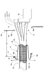
- FIG. 1 is a partial sectional view showing a configuration example of a grommet 10 according to an embodiment of the present invention (the entire grommet 10 and a part of the wire harness 20 are represented by a cross section (shaded portion)).
- a state before the grommet 10 attached to the wire harness 20 is coupled to the dash panel 30 is shown.
- the connector 21 (21a, 21b, 21c) at the tip of the wire harness 20 to which the grommet 10 is attached passes through the panel opening 31 of the dash panel 30 from the engine room ER side at the front of the vehicle and passes through the vehicle compartment VI. It is assumed that it is connected to the corresponding connector in the junction box 40 of the instrument panel installed in the (space where the air conditioner unit or the like is installed).
- FIG. 2 is a view of the plane defined by the line II-II in FIG. 1 as viewed from the direction of the arrow AR1.
- the grommet 10 is a member formed of a synthetic rubber such as EPDM (Ethylene-Propylene-Diene-Monomer) rubber, and mainly includes a wire harness connecting portion 11, an intermediate extending portion 12, and a panel connecting portion 13.
- EPDM Ethylene-Propylene-Diene-Monomer
- the wire harness coupling portion 11 is a portion that is liquid-tightly coupled to the outer periphery of the wire harness 20.
- the wire harness coupling portion 11 has a cylindrical shape and is between the outer surface of the wire harness 20 and the inner surface of the wire harness coupling portion 11.
- an adhesive such as a modified silicone resin adhesive, the wire harness 20 is liquid-tightly bonded.
- bond part 11 may be hardened
- the intermediate extension portion 12 is a flexible portion having a variable shape extending between the wire harness joint portion 11 and the panel joint portion 13.
- the intermediate extension portion 12 extends in the direction of the wire harness 20 (facing the tip where the connector 21 is located).
- the extending portion shape holding portion 12a is provided for holding the shape in a state of curving in a direction opposite to the direction).
- maintenance part 12a is formed with the same material (for example, it is EPDM rubber) as the other part (The wire harness coupling
- the intermediate extension portion 12 is formed in a state of being thicker than other portions or by applying a curing agent. Regardless of whether or not it is rolled up, it is configured to maintain its shape.
- the grommet 10 is preferably supplied in a state where the intermediate extension 12 is rolled up. This is because the operator can enter the connector connection work without having to manually lift up the intermediate extension 12.
- the panel coupling portion 13 is a portion that is liquid-tightly coupled to the peripheral edge of the panel opening 31 of the dash panel 30, and has, for example, an opening that matches the shape of the peripheral edge of the panel opening 31 (for example, a rectangular shape).
- the peripheral edge thereof is reinforced by the plate portion 14 so as to be fastened by a fastening member such as a bolt.
- bond part 13 can ensure rigidity higher than the intermediate
- FIG. 1 when the intermediate extension portion 12 is in a state of being rolled up, the extension of the wire harness 20 is extended by the extension portion shape holding portion 12a in the immediate vicinity of the joint portions 13a and 13b. A curved portion 12b is formed that reverses the intermediate extending portion 12 raised in the direction opposite to the existing direction in the extending direction of the wire harness 20 again.
- the panel coupling portion 13 is in a state in which the connector 21 of the wire harness 20 is connected to the corresponding connector in the junction box 40 when the intermediate extension portion 12 is rolled up as shown in FIG.
- the work space (work) when the connector 21 of the wire harness 20 is connected to the corresponding connector in the junction box 40 is held so as to be located at a certain distance D or more from the dash panel 30 (for example, 150 millimeters). It is a space in which a person can insert a hand, and is also referred to as “hand space”).
- the plate portion 14 is a member for reinforcing the peripheral edge of the panel coupling portion 13 and is formed of, for example, a metal such as iron and is fastened to the dash panel 30 together with the panel coupling portion 13 by a fastening member such as a bolt.
- the panel coupling portion 13 (plate portion 14) has a rectangular shape that conforms to the peripheral shape (rectangular shape) of the panel opening 31 as shown in FIG. As long as it can be tightly sealed, it does not necessarily have to conform to the shape of the panel opening 31, and may have an opening of another shape such as a circle, an ellipse, or a polygon.
- the wire harness 20 includes three connectors 21a, 21b, and 21c at the tip thereof, and is connected to the corresponding connector in the junction box 40 through the single panel opening 31.
- One or two connectors may be provided, or four or more connectors may be provided.
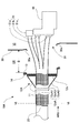
- FIG. 3 is a partial cross-sectional view showing a configuration example of the grommet 10 according to the embodiment of the present invention, as in FIG. 1, and shows a state after the grommet 10 is coupled to the dash panel 30.
- FIG. 4 is a view of the plane defined by the line IV-IV in FIG. 3 as viewed from the direction of the arrow AR2.
- the operator manually connects the connector 21 of the wire harness 20 to the corresponding connector in the junction box 40, and then places the intermediate extension 12 in the state of being rolled up as shown in FIG. 1 in the direction of the dash panel 30.
- the panel coupling portion 13 is brought into close contact with the engine room ER side surface 30a (see FIG. 1) at the periphery of the panel opening 31 of the dash panel 30, and the panel coupling portion 13 and the plate
- the panel coupling portion 13 is fastened to the dash panel 30 together with the plate portion 14 by bolts 32a to 32d (see FIG. 4) inserted into bolt holes 15a to 15d (see FIG. 2) penetrating the portion 14, respectively.
- the extension portion shape holding portion 12 a is formed when the intermediate extension portion 12 is lifted in the direction opposite to the direction of the dash panel 30, and the intermediate extension portion 12. In any case where is pulled down in the direction of the dash panel 30, the shape (a state of warping in the direction opposite to the extending direction of the wire harness 20) is maintained.
- the extension in a state where the intermediate extension portion 12 is warped in a direction opposite to the extension direction of the wire harness 20.
- the curved part 12b is formed by reversing the direction in the extending direction of the wire harness 20 and extending toward the dash panel 30.
- the operator uses the characteristic of the extension shape holding portion 12a that maintains its shape regardless of the state of the intermediate extension portion 12, and extends in the direction of the dash panel 30 as shown in FIG. It is also possible to manually lift up the intermediate extension 12 and return it to the rolled-up state as shown in FIG.
- the grommet 10 allows the intermediate extension portion 12 to extend in the direction opposite to the extension direction of the wire harness 20 when the operator connects the connector 21 of the wire harness 20 to the corresponding connector in the junction box 40. Therefore, the work space for the connection can be secured without any special manual work by the worker, and the workability can be further improved.
- the grommet 10 can repeatedly go back and forth between the state in which the intermediate extension portion 12 is lifted and the state in which the intermediate extension portion 12 is pulled down, the operator has pulled down the intermediate extension portion 12. Even if the connection work of the connector 21 of the wire harness 20 is performed again later, the intermediate extension portion 12 can be lifted to secure a work space.
- the intermediate extension part 12 is held in a state where the extension direction is reversed at two places of the extension part shape holding part 12a and the bending part 12b and the panel coupling part 13 is finally directed to the dash panel 30.
- the panel coupling portion 13 is rolled up and the panel coupling portion 13 is directed in a direction opposite to the direction of the dash panel 30 (the panel coupling portion 13 is coupled to the dash panel 30).
- the intermediate extension portion 12 and the panel coupling portion 13 may be held.
- FIGS. 1 to 4 Components common to the grommet 10 shown in FIGS. 1 to 4 are referred to using the same reference numerals.
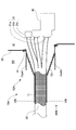
- FIG. 5 is a partial cross-sectional view showing a configuration example of a grommet 10A according to another embodiment of the present invention (the entire grommet 10A and a part of the wire harness 20 are represented by a cross section (shaded portion)).
- the connector 21 (21a, 21b, 21c) at the tip of the wire harness 20 to which the grommet 10A is attached passes through the panel opening 31 of the dash panel 30 from the engine room ER side at the front of the vehicle and passes through the vehicle compartment VI. It is assumed that it is connected to the corresponding connector in the junction box 40 of the instrument panel installed in the (space where the air conditioner unit or the like is installed).
- FIG. 6 is a view of the plane defined by the line VI-VI in FIG. 5 as seen from the direction of the arrow AR3.
- the grommet 10A includes an intermediate extension portion 12A having a bellows structure portion 12c and an extension portion shape holding portion 12aA for holding the bellows structure portion 12c in a folded state.
- the grommet 10 is the same as the grommet 10 in other points. Therefore, the difference will be described in detail while omitting the description of the common points.
- the intermediate extending portion 12A is a flexible portion (a part of the grommet 10A) having a variable shape extending between the wire harness connecting portion 11 and the panel connecting portion 13, and the connector 21 of the wire harness 20 is connected to the junction box 40. From the folded state in which the panel coupling portion 13 is held at a certain distance D (for example, 150 millimeters) or more from the dash panel 30 to the extended state in which the panel coupling portion 13 is brought into close contact with the dash panel 30.
- the bellows structure part 12c which changes a shape is provided.
- the extension part shape holding part 12aA is a constituent element of the intermediate extension part 12A, and is the same material (for example, EPDM rubber) as other parts of the grommet 10A (the wire harness joint part 11 and the panel joint part 13). And includes a bellows structure portion folding tongue 12aA1, 12aA2 and a tongue holding tape 12aA3.
- the bellows structure part folding tongues 12aA1 and 12aA2 are members extending in a direction opposite to the extending direction of the wire harness 20 from the joint portion between the bellows structure part 12c and the panel coupling part 13, and fold the bellows structure part 12c. By holding each free end in contact with the outer surface of the wire harness coupling portion 11 while still in the state, the folded state of the bellows structure portion 12c can be maintained.
- the tongue holding tape 12aA3 is a fastening member for holding the respective free ends of the bellows structure folding tongues 12aA1 and 12aA2 in contact with the outer surface of the wire harness coupling portion 11, such as a wire harness 20 (wire harness). It is a ring-shaped elastic member that is arranged on the outer periphery of the coupling part 11) so as to be stretchable.
- the tongue holding tape 12aA3 may be formed of a material different from that of the other parts of the grommet 10A.
- the grommet 10A is preferably supplied in a state in which the bellows structure portion 12c of the intermediate extension portion 12A is folded.
- the extending portion shape holding portion 12aA includes two bellows structure folding tongue portions arranged on both sides (up and down) across the central axis of the wire harness 20, as shown in FIG. Although it is configured to include 12aA1 and 12aA2, it may include one or three or more bellows structure folding tongues.
- the bellows structure portion folding tongues 12aA1 and 12aA2 are held in contact with the outer periphery of the wire harness 20 (wire harness coupling portion 11) by the tongue holding tape 12aA3.
- the adhesive may be held on the outer periphery of the wire harness 20 (wire harness coupling portion 11) so as to be peeled off.
- FIG. 7 is a partial cross-sectional view showing a configuration example of the grommet 10 ⁇ / b> A, similar to FIG. 5, and shows a state after the grommet 10 ⁇ / b> A is coupled to the dash panel 30.
- FIG. 8 is a view of the plane defined by the line VIII-VIII in FIG. 7 as seen from the direction of the arrow AR4.
- the operator manually connects the connector 21 of the wire harness 20 to the corresponding connector in the junction box 40 and then cuts the tongue holding tape 12aA3 or in a direction opposite to the extending direction of the wire harness 20.
- the free ends of the bellows structure part folding tongues 12aA1 and 12aA2 are released by shifting.
- the operator stretches the bellows structure portion 12c of the intermediate extension portion 12A in the folded state as shown in FIG. 5 so as to spread toward the dash panel 30, and as shown in FIG.
- the panel coupling portion 13 is brought into close contact with the surface 30a (see FIG. 5) on the engine room ER side at the periphery of the panel opening 31 of the dash panel 30, and the bolt holes 15a ⁇
- the panel coupling portion 13 is fastened to the dash panel 30 together with the plate portion 14 by bolts 32a to 32d (see FIG. 8) inserted into 15d (see FIG. 6).
- the operator manually folds the bellows structure portion 12c extending in the direction of the dash panel 30 by hand, and the tongue is shifted in the direction opposite to the extending direction of the wire harness 20.
- the holding bellows structure portion 12c is folded as shown in FIG. 5 by re-contacting and holding the free ends of the bellows structure portion folding tongues 12aA1 and 12aA2 to the outer surface of the wire harness coupling portion 11 with the holding tape 12aA3. It is also possible to return to the restored state.
- the grommet 10A holds the bellows structure portion 12c of the intermediate extension portion 12A in a folded state when the operator connects the connector 21 of the wire harness 20 to the corresponding connector in the junction box 40. Further, it is possible to secure a work space for the connection without special manual work by the worker, and the workability can be further improved.
- the grommet 10A folds the bellows structure portion 12c when the tongue holding portion 12aA1 and 12aA2 are released from the outer surface of the wire harness coupling portion 11 by shifting the position of the tongue holding tape 12aA3. Since the state and the state in which the bellows structure portion 12c is extended can be repeatedly moved, the operator may perform the connection work of the connector 21 of the wire harness 20 again after extending the bellows structure portion 12c. Even if it exists, the work space can be ensured by folding the bellows structure part 12c.
- the grommet 10A can extend the bellows structure part 12c in the folded state so as to spread toward the dash panel 30, the opening size of the panel coupling part 13 can be set flexibly. It is possible to deal with panel openings 31 of various sizes including a relatively large panel opening 31 through which a plurality of connectors pass.
- bellows structure part 12c may be configured to be stretched in a cylindrical shape along the wire harness 20 without expanding the skirt. In that case, you may make it arrange
- the bellows structure portion 12 c is held so that its folded portion is overlapped in a direction perpendicular to the outer surface of the wire harness 20, but in a direction parallel to the wire harness 20. You may make it hold
- bellows structure portion 12c may be held such that its folded portion is overlapped in a direction opposite to the extending direction of the wire harness 20 beyond the direction perpendicular to the outer surface of the wire harness 20.
- the grommet 10A holds the bellows structure portion 12c in a folded state using the bellows structure portion folding tongues 12aA1 and 12aA2 and the tongue holding tape 12aA3. While omitting the portions 12aA1, 12aA2 and the tongue holding tape 12aA3, a part of the flexible intermediate extending portion 12A having no bellows structure is raised in a direction opposite to the extending direction of the wire harness 20 ( For example, the intermediate extension portion 12A and the panel coupling portion 13 are joined to each other on the outer surface of the wire harness coupling portion 11 with an adhesive, and the intermediate extension portion 12A is lifted up. You may make it hold
- the grommet 10A partially changes the thickness and flexibility of the intermediate extension portion 12A after omitting the bellows structure folding tongue portions 12aA1 and 12aA2 and the tongue holding tape 12aA3.
- a certain shape holding force that can hold the bellows structure portion 12c in a folded state is generated, and the panel coupling portion 13 is brought into close contact with the dash panel 30 by the operator applying force.
- the bellows structure portion 12c may be returned to the folded state when the operator releases his / her hand so that the panel coupling portion 13 naturally moves away from the dash panel 30 to a predetermined position.
- the intermediate extension portion 12A does not necessarily adopt the bellows structure portion 12c, and may adopt a structure that extends smoothly.
- the grommets 10 and 10A are attached to the wire harness 20 having a circular cross section, but may be attached to a wire harness having another cross-sectional shape such as an ellipse or a rectangle.
Landscapes
- Engineering & Computer Science (AREA)
- Architecture (AREA)
- Civil Engineering (AREA)
- Structural Engineering (AREA)
- Mechanical Engineering (AREA)
- Manufacturing & Machinery (AREA)
- Microelectronics & Electronic Packaging (AREA)
- Installation Of Indoor Wiring (AREA)
- Insulating Bodies (AREA)
Abstract
Description
11 ワイヤハーネス結合部
12、12A 中間延在部
12a、12aA 延在部形状保持部
12aA1、12aA2 蛇腹構造部折り畳み用舌部
12aA3 舌部保持テープ
12b 湾曲部
12c 蛇腹構造部
13 パネル結合部
14 プレート部
15a~15d ボルト孔
20 ワイヤハーネス
21、21a~21c コネクタ
30 ダッシュパネル
30a ダッシュパネル表面
31 パネル開口
32a~32d ボルト
ER エンジンルーム
VI 車室
Claims (5)
- ワイヤハーネスに液密に結合されるワイヤハーネス結合部と、
パネル開口に液密に結合可能なパネル結合部と、
前記ワイヤハーネス結合部と前記パネル結合部との間に形状可変に延在する延在部と、
前記パネル結合部を前記パネル開口に液密に結合する場合における前記ワイヤハーネス結合部と前記パネル結合部との間の前記ワイヤハーネスの長さ方向における距離に比べて該距離がより短い状態の前記延在部の形状を保持する延在部形状保持部と、
を備えることを特徴とするグロメット。 - 前記延在部形状保持部は、前記延在部が捲れ上がった状態の前記延在部の形状を保持する形状保持構造を有する、
ことを特徴とする請求項1に記載のグロメット。 - 前記形状保持構造は、前記延在部が前記ワイヤハーネス結合部の方向に捲れ上がった状態と前記延在部が前記パネル結合部の方向に延びた状態とを切り替え可能にする、
ことを特徴とする請求項2に記載のグロメット。 - 前記延在部は、蛇腹構造を有し、
前記延在部形状保持部は、前記延在部の蛇腹構造を折り畳んだ状態の前記延在部の形状を保持する、
ことを特徴とする請求項1に記載のグロメット。 - ワイヤハーネスに液密に結合されるワイヤハーネス結合部と、パネル開口に液密に結合可能なパネル結合部と、該ワイヤハーネス結合部と該パネル結合部との間に形状可変に延在する延在部と、該延在部の形状を保持する延在部形状保持部と、を備えたグロメットの該パネル開口への取り付け方法であって、
前記延在部形状保持部により、前記パネル結合部を前記パネル開口に液密に結合する場合における前記ワイヤハーネス結合部と前記パネル結合部との間の前記ワイヤハーネスの長さ方向における距離に比べて該距離がより短い状態の前記延在部の形状を保持したまま、前記ワイヤハーネスの先端にあるコネクタと前記パネル開口内に配置された対応するコネクタとを接続するステップと、
前記延在部の形状を変えて前記距離をより長くし、前記パネル結合部を前記パネル開口に取り付けるステップと、
を備えることを特徴とするグロメット取り付け方法。
Priority Applications (5)
| Application Number | Priority Date | Filing Date | Title |
|---|---|---|---|
| PCT/JP2011/050524 WO2012095986A1 (ja) | 2011-01-14 | 2011-01-14 | グロメット及びその取り付け方法 |
| CN201180064319.5A CN103299497B (zh) | 2011-01-14 | 2011-01-14 | 护环及其安装方法 |
| US13/978,555 US8835778B2 (en) | 2011-01-14 | 2011-01-14 | Grommet and method of mounting thereof |
| EP11855701.6A EP2665145B1 (en) | 2011-01-14 | 2011-01-14 | Grommet and method of installing thereof |
| JP2012552606A JP5553113B2 (ja) | 2011-01-14 | 2011-01-14 | グロメット及びその取り付け方法 |
Applications Claiming Priority (1)
| Application Number | Priority Date | Filing Date | Title |
|---|---|---|---|
| PCT/JP2011/050524 WO2012095986A1 (ja) | 2011-01-14 | 2011-01-14 | グロメット及びその取り付け方法 |
Publications (1)
| Publication Number | Publication Date |
|---|---|
| WO2012095986A1 true WO2012095986A1 (ja) | 2012-07-19 |
Family
ID=46506907
Family Applications (1)
| Application Number | Title | Priority Date | Filing Date |
|---|---|---|---|
| PCT/JP2011/050524 Ceased WO2012095986A1 (ja) | 2011-01-14 | 2011-01-14 | グロメット及びその取り付け方法 |
Country Status (5)
| Country | Link |
|---|---|
| US (1) | US8835778B2 (ja) |
| EP (1) | EP2665145B1 (ja) |
| JP (1) | JP5553113B2 (ja) |
| CN (1) | CN103299497B (ja) |
| WO (1) | WO2012095986A1 (ja) |
Families Citing this family (4)
| Publication number | Priority date | Publication date | Assignee | Title |
|---|---|---|---|---|
| CN108347004A (zh) * | 2018-04-17 | 2018-07-31 | 广东电网有限责任公司 | 一种低压导线外露导体快速包封绝缘套 |
| JP7268576B2 (ja) * | 2019-10-30 | 2023-05-08 | 住友電装株式会社 | グロメット |
| JP7616034B2 (ja) * | 2021-11-26 | 2025-01-17 | 株式会社豊田自動織機 | 電動圧縮機 |
| DE102023211773B3 (de) | 2023-11-27 | 2025-01-30 | Volkswagen Aktiengesellschaft | Tülle zum Halten von Leitungen, Verfahren zum Montieren einer Tülle sowie Kraftfahrzeug |
Citations (5)
| Publication number | Priority date | Publication date | Assignee | Title |
|---|---|---|---|---|
| JPH09284953A (ja) * | 1996-04-08 | 1997-10-31 | Yazaki Corp | 長尺筒状部付きのグロメット |
| JP2000358315A (ja) * | 1999-06-11 | 2000-12-26 | Calsonic Kansei Corp | グロメット |
| JP2001186623A (ja) * | 1999-12-24 | 2001-07-06 | Yazaki Corp | モジュール用コネクタ取付構造 |
| JP2001309528A (ja) | 2000-04-21 | 2001-11-02 | Yazaki Corp | パネル貫通型コネクタの防水構造 |
| JP2003111249A (ja) * | 2001-09-28 | 2003-04-11 | Fujikura Ltd | グロメット |
Family Cites Families (15)
| Publication number | Priority date | Publication date | Assignee | Title |
|---|---|---|---|---|
| JPH0616192Y2 (ja) * | 1988-12-27 | 1994-04-27 | トヨタ自動車株式会社 | ワイヤハーネス用グロメット |
| JP2947000B2 (ja) * | 1993-06-08 | 1999-09-13 | 住友電装株式会社 | ワイヤハーネスの防水方法および防水構造 |
| JP3757106B2 (ja) * | 2000-10-27 | 2006-03-22 | 矢崎総業株式会社 | グロメット |
| JP3825278B2 (ja) * | 2001-05-29 | 2006-09-27 | 矢崎総業株式会社 | グロメット |
| JP2003011249A (ja) * | 2001-07-03 | 2003-01-15 | Dainippon Printing Co Ltd | 紙カップ成形機 |
| US6927338B2 (en) * | 2002-10-09 | 2005-08-09 | The Xlo Group Of Companies, Inc. | Wire pass through seal with grommets |
| JP3915673B2 (ja) * | 2002-11-20 | 2007-05-16 | 住友電装株式会社 | グロメットとプロテクタの車体取付構造 |
| US6897380B2 (en) * | 2002-11-29 | 2005-05-24 | Sumitomo Wiring Systems, Ltd. | Grommet for a wire harness |
| JP4405276B2 (ja) | 2004-02-16 | 2010-01-27 | 矢崎総業株式会社 | 車両用ドアハーネスの防水構造および配索方法 |
| FR2904398B1 (fr) | 2006-07-25 | 2008-09-26 | Societe Des Polymeres Barre-Thomas | Dispositif de coudage de tuyau souple, notamment pour un fourreau passe-cables de porte ou de volet de vehicule automobile |
| JP4791396B2 (ja) | 2007-03-19 | 2011-10-12 | 矢崎総業株式会社 | グロメットおよびその組付方法 |
| JP2009201179A (ja) * | 2008-02-19 | 2009-09-03 | Yazaki Corp | グロメット |
| JP5157513B2 (ja) * | 2008-02-20 | 2013-03-06 | 住友電装株式会社 | グロメット |
| JP2012239353A (ja) * | 2011-05-13 | 2012-12-06 | Sumitomo Wiring Syst Ltd | グロメット |
| JP5747694B2 (ja) * | 2011-07-06 | 2015-07-15 | 住友電装株式会社 | グロメット |
-
2011
- 2011-01-14 EP EP11855701.6A patent/EP2665145B1/en not_active Not-in-force
- 2011-01-14 WO PCT/JP2011/050524 patent/WO2012095986A1/ja not_active Ceased
- 2011-01-14 JP JP2012552606A patent/JP5553113B2/ja not_active Expired - Fee Related
- 2011-01-14 US US13/978,555 patent/US8835778B2/en not_active Expired - Fee Related
- 2011-01-14 CN CN201180064319.5A patent/CN103299497B/zh not_active Expired - Fee Related
Patent Citations (5)
| Publication number | Priority date | Publication date | Assignee | Title |
|---|---|---|---|---|
| JPH09284953A (ja) * | 1996-04-08 | 1997-10-31 | Yazaki Corp | 長尺筒状部付きのグロメット |
| JP2000358315A (ja) * | 1999-06-11 | 2000-12-26 | Calsonic Kansei Corp | グロメット |
| JP2001186623A (ja) * | 1999-12-24 | 2001-07-06 | Yazaki Corp | モジュール用コネクタ取付構造 |
| JP2001309528A (ja) | 2000-04-21 | 2001-11-02 | Yazaki Corp | パネル貫通型コネクタの防水構造 |
| JP2003111249A (ja) * | 2001-09-28 | 2003-04-11 | Fujikura Ltd | グロメット |
Non-Patent Citations (1)
| Title |
|---|
| See also references of EP2665145A4 |
Also Published As
| Publication number | Publication date |
|---|---|
| JP5553113B2 (ja) | 2014-07-16 |
| EP2665145A4 (en) | 2013-11-20 |
| CN103299497A (zh) | 2013-09-11 |
| US8835778B2 (en) | 2014-09-16 |
| US20130292158A1 (en) | 2013-11-07 |
| EP2665145A1 (en) | 2013-11-20 |
| CN103299497B (zh) | 2016-08-10 |
| EP2665145B1 (en) | 2016-12-21 |
| JPWO2012095986A1 (ja) | 2014-06-09 |
Similar Documents
| Publication | Publication Date | Title |
|---|---|---|
| CN103415969B (zh) | 护线套的密封结构 | |
| CN103733456B (zh) | 线束 | |
| JP5553113B2 (ja) | グロメット及びその取り付け方法 | |
| JP6389674B2 (ja) | クランプ及び該クランプを備えたワイヤハーネス | |
| CN110582913A (zh) | 线束的固定结构 | |
| JP2018190696A (ja) | 配線モジュール、複合配線モジュール及び配線モジュール付固定対象部材 | |
| CN106058756A (zh) | 一种线束保护装置 | |
| JP2016088408A (ja) | ワイヤーハーネスの組み付け方法、干渉抑制部材及びワイヤーハーネスの組付構造 | |
| JP2008284966A (ja) | サービスホールカバーの取付方法及びそのためのサービスホールカバー | |
| JP2016210356A (ja) | ワイヤハーネス付き防音材 | |
| US10099632B1 (en) | Integrated bracket for trim ring reinforcement | |
| JP6166673B2 (ja) | 車両用バックドア | |
| WO2018207641A1 (ja) | 配線モジュール、複合配線モジュール及び配線モジュール付固定対象部材 | |
| JP2002058142A (ja) | 補助具付グロメット | |
| CN110944876A (zh) | 机动车辆的折叠内衬板 | |
| JP5512197B2 (ja) | 車両用ダッシュサイレンサ | |
| JP4062218B2 (ja) | グロメット | |
| JP6116412B2 (ja) | ワイヤハーネスの固定構造 | |
| JP2017065376A (ja) | 車載スピーカの取付構造 | |
| CN116802083A (zh) | 具有适用于使黏性密封垫粘合在其自身上的壁的设备 | |
| JPH0523376Y2 (ja) | ||
| JPH1125786A (ja) | グロメット | |
| JP5761165B2 (ja) | グロメット | |
| JP6202682B2 (ja) | 自動車用内装部品 | |
| CN110834592B (zh) | 具有集成的翻倍的加强部段的平面的机动车覆盖构件 |
Legal Events
| Date | Code | Title | Description |
|---|---|---|---|
| 121 | Ep: the epo has been informed by wipo that ep was designated in this application |
Ref document number: 11855701 Country of ref document: EP Kind code of ref document: A1 |
|
| ENP | Entry into the national phase |
Ref document number: 2012552606 Country of ref document: JP Kind code of ref document: A |
|
| REEP | Request for entry into the european phase |
Ref document number: 2011855701 Country of ref document: EP |
|
| WWE | Wipo information: entry into national phase |
Ref document number: 2011855701 Country of ref document: EP |
|
| WWE | Wipo information: entry into national phase |
Ref document number: 13978555 Country of ref document: US |
|
| NENP | Non-entry into the national phase |
Ref country code: DE |