WO2012096146A1 - 映像符号化装置、映像復号装置、映像符号化方法、映像復号方法及びプログラム - Google Patents
映像符号化装置、映像復号装置、映像符号化方法、映像復号方法及びプログラム Download PDFInfo
- Publication number
- WO2012096146A1 WO2012096146A1 PCT/JP2012/000045 JP2012000045W WO2012096146A1 WO 2012096146 A1 WO2012096146 A1 WO 2012096146A1 JP 2012000045 W JP2012000045 W JP 2012000045W WO 2012096146 A1 WO2012096146 A1 WO 2012096146A1
- Authority
- WO
- WIPO (PCT)
- Prior art keywords
- motion vectors
- inter
- image block
- predetermined area
- encoding
- Prior art date
- Legal status (The legal status is an assumption and is not a legal conclusion. Google has not performed a legal analysis and makes no representation as to the accuracy of the status listed.)
- Ceased
Links
Images


Classifications
-
- H—ELECTRICITY
- H04—ELECTRIC COMMUNICATION TECHNIQUE
- H04N—PICTORIAL COMMUNICATION, e.g. TELEVISION
- H04N19/00—Methods or arrangements for coding, decoding, compressing or decompressing digital video signals
- H04N19/50—Methods or arrangements for coding, decoding, compressing or decompressing digital video signals using predictive coding
- H04N19/503—Methods or arrangements for coding, decoding, compressing or decompressing digital video signals using predictive coding involving temporal prediction
-
- H—ELECTRICITY
- H04—ELECTRIC COMMUNICATION TECHNIQUE
- H04N—PICTORIAL COMMUNICATION, e.g. TELEVISION
- H04N19/00—Methods or arrangements for coding, decoding, compressing or decompressing digital video signals
- H04N19/10—Methods or arrangements for coding, decoding, compressing or decompressing digital video signals using adaptive coding
- H04N19/102—Methods or arrangements for coding, decoding, compressing or decompressing digital video signals using adaptive coding characterised by the element, parameter or selection affected or controlled by the adaptive coding
- H04N19/103—Selection of coding mode or of prediction mode
- H04N19/109—Selection of coding mode or of prediction mode among a plurality of temporal predictive coding modes
-
- H—ELECTRICITY
- H04—ELECTRIC COMMUNICATION TECHNIQUE
- H04N—PICTORIAL COMMUNICATION, e.g. TELEVISION
- H04N19/00—Methods or arrangements for coding, decoding, compressing or decompressing digital video signals
- H04N19/10—Methods or arrangements for coding, decoding, compressing or decompressing digital video signals using adaptive coding
- H04N19/102—Methods or arrangements for coding, decoding, compressing or decompressing digital video signals using adaptive coding characterised by the element, parameter or selection affected or controlled by the adaptive coding
- H04N19/119—Adaptive subdivision aspects, e.g. subdivision of a picture into rectangular or non-rectangular coding blocks
-
- H—ELECTRICITY
- H04—ELECTRIC COMMUNICATION TECHNIQUE
- H04N—PICTORIAL COMMUNICATION, e.g. TELEVISION
- H04N19/00—Methods or arrangements for coding, decoding, compressing or decompressing digital video signals
- H04N19/10—Methods or arrangements for coding, decoding, compressing or decompressing digital video signals using adaptive coding
- H04N19/102—Methods or arrangements for coding, decoding, compressing or decompressing digital video signals using adaptive coding characterised by the element, parameter or selection affected or controlled by the adaptive coding
- H04N19/12—Selection from among a plurality of transforms or standards, e.g. selection between discrete cosine transform [DCT] and sub-band transform or selection between H.263 and H.264
- H04N19/122—Selection of transform size, e.g. 8x8 or 2x4x8 DCT; Selection of sub-band transforms of varying structure or type
-
- H—ELECTRICITY
- H04—ELECTRIC COMMUNICATION TECHNIQUE
- H04N—PICTORIAL COMMUNICATION, e.g. TELEVISION
- H04N19/00—Methods or arrangements for coding, decoding, compressing or decompressing digital video signals
- H04N19/10—Methods or arrangements for coding, decoding, compressing or decompressing digital video signals using adaptive coding
- H04N19/134—Methods or arrangements for coding, decoding, compressing or decompressing digital video signals using adaptive coding characterised by the element, parameter or criterion affecting or controlling the adaptive coding
- H04N19/136—Incoming video signal characteristics or properties
- H04N19/137—Motion inside a coding unit, e.g. average field, frame or block difference
- H04N19/139—Analysis of motion vectors, e.g. their magnitude, direction, variance or reliability
-
- H—ELECTRICITY
- H04—ELECTRIC COMMUNICATION TECHNIQUE
- H04N—PICTORIAL COMMUNICATION, e.g. TELEVISION
- H04N19/00—Methods or arrangements for coding, decoding, compressing or decompressing digital video signals
- H04N19/10—Methods or arrangements for coding, decoding, compressing or decompressing digital video signals using adaptive coding
- H04N19/134—Methods or arrangements for coding, decoding, compressing or decompressing digital video signals using adaptive coding characterised by the element, parameter or criterion affecting or controlling the adaptive coding
- H04N19/146—Data rate or code amount at the encoder output
- H04N19/147—Data rate or code amount at the encoder output according to rate distortion criteria
-
- H—ELECTRICITY
- H04—ELECTRIC COMMUNICATION TECHNIQUE
- H04N—PICTORIAL COMMUNICATION, e.g. TELEVISION
- H04N19/00—Methods or arrangements for coding, decoding, compressing or decompressing digital video signals
- H04N19/10—Methods or arrangements for coding, decoding, compressing or decompressing digital video signals using adaptive coding
- H04N19/169—Methods or arrangements for coding, decoding, compressing or decompressing digital video signals using adaptive coding characterised by the coding unit, i.e. the structural portion or semantic portion of the video signal being the object or the subject of the adaptive coding
- H04N19/17—Methods or arrangements for coding, decoding, compressing or decompressing digital video signals using adaptive coding characterised by the coding unit, i.e. the structural portion or semantic portion of the video signal being the object or the subject of the adaptive coding the unit being an image region, e.g. an object
- H04N19/176—Methods or arrangements for coding, decoding, compressing or decompressing digital video signals using adaptive coding characterised by the coding unit, i.e. the structural portion or semantic portion of the video signal being the object or the subject of the adaptive coding the unit being an image region, e.g. an object the region being a block, e.g. a macroblock
-
- H—ELECTRICITY
- H04—ELECTRIC COMMUNICATION TECHNIQUE
- H04N—PICTORIAL COMMUNICATION, e.g. TELEVISION
- H04N19/00—Methods or arrangements for coding, decoding, compressing or decompressing digital video signals
- H04N19/46—Embedding additional information in the video signal during the compression process
-
- H—ELECTRICITY
- H04—ELECTRIC COMMUNICATION TECHNIQUE
- H04N—PICTORIAL COMMUNICATION, e.g. TELEVISION
- H04N19/00—Methods or arrangements for coding, decoding, compressing or decompressing digital video signals
- H04N19/50—Methods or arrangements for coding, decoding, compressing or decompressing digital video signals using predictive coding
- H04N19/503—Methods or arrangements for coding, decoding, compressing or decompressing digital video signals using predictive coding involving temporal prediction
- H04N19/51—Motion estimation or motion compensation
-
- H—ELECTRICITY
- H04—ELECTRIC COMMUNICATION TECHNIQUE
- H04N—PICTORIAL COMMUNICATION, e.g. TELEVISION
- H04N19/00—Methods or arrangements for coding, decoding, compressing or decompressing digital video signals
- H04N19/60—Methods or arrangements for coding, decoding, compressing or decompressing digital video signals using transform coding
- H04N19/61—Methods or arrangements for coding, decoding, compressing or decompressing digital video signals using transform coding in combination with predictive coding
-
- H—ELECTRICITY
- H04—ELECTRIC COMMUNICATION TECHNIQUE
- H04N—PICTORIAL COMMUNICATION, e.g. TELEVISION
- H04N19/00—Methods or arrangements for coding, decoding, compressing or decompressing digital video signals
- H04N19/65—Methods or arrangements for coding, decoding, compressing or decompressing digital video signals using error resilience
-
- H—ELECTRICITY
- H04—ELECTRIC COMMUNICATION TECHNIQUE
- H04N—PICTORIAL COMMUNICATION, e.g. TELEVISION
- H04N19/00—Methods or arrangements for coding, decoding, compressing or decompressing digital video signals
- H04N19/70—Methods or arrangements for coding, decoding, compressing or decompressing digital video signals characterised by syntax aspects related to video coding, e.g. related to compression standards
-
- H—ELECTRICITY
- H04—ELECTRIC COMMUNICATION TECHNIQUE
- H04N—PICTORIAL COMMUNICATION, e.g. TELEVISION
- H04N19/00—Methods or arrangements for coding, decoding, compressing or decompressing digital video signals
- H04N19/90—Methods or arrangements for coding, decoding, compressing or decompressing digital video signals using coding techniques not provided for in groups H04N19/10-H04N19/85, e.g. fractals
- H04N19/91—Entropy coding, e.g. variable length coding [VLC] or arithmetic coding
Definitions
- the present invention relates to a video encoding device, a video decoding device, a video encoding method, a video decoding method, and a program using a hierarchical encoding unit.
- Non-Patent Document 1 discloses a general video encoding method and video decoding method.
- the video encoding device described in Non-Patent Document 1 is configured as shown in FIG.
- the video encoding device shown in FIG. 17 is referred to as a general video encoding device.
- a container 17 includes a transform / quantizer 101, an entropy encoder 102, an inverse transform / inverse quantizer 103, a buffer 104, a predictor 105, a multiplexer 106, and a coding control.
- a container 108 is provided.
- the video encoding apparatus shown in FIG. 17 divides a frame into blocks each having a size of 16 ⁇ 16 pixels called a macro block (MB), and encodes each MB in order from the upper left of the frame.
- MB macro block
- FIG. 18 is an explanatory diagram showing an example of block division when the spatial resolution of the frame is QCIF (Quarter Common Intermediate Format).
- QCIF Quadrater Common Intermediate Format
- the input video divided into blocks is a prediction error image obtained by subtracting the prediction signal supplied from the predictor 105, and is input to the transform / quantizer 101.
- the inter prediction signal is also referred to as an inter-frame prediction signal.
- the intra prediction signal is a prediction signal generated based on an image of a reconstructed picture having the same display time as the current picture stored in the buffer 104.
- Intra_4 ⁇ 4 and Intra_8 ⁇ 8 are intra predictions of 4 ⁇ 4 block size and 8 ⁇ 8 block size, respectively, with reference to (a) and (c) of FIG.
- circles ( ⁇ ) in the drawing are reference pixels used for intra prediction, that is, pixels of a reconstructed picture having the same display time as the current picture.
- Intra_4 ⁇ 4 intra prediction the reconstructed neighboring pixels are used as reference pixels as they are, and prediction signals are formed by padding (extrapolating) reference pixels in nine types of directions shown in FIG.
- Intra_8 ⁇ 8 intra prediction peripheral pixels of the reconstructed picture image are smoothed by the low-pass filter (1/2, 1/4, 1/2) described under the right arrow in FIG.
- a prediction signal is formed by extrapolating the reference pixels in nine types of directions shown in FIG.
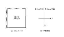
- Intra — 16 ⁇ 16 is an intra prediction of 16 ⁇ 16 block size with reference to FIG.
- circles ( ⁇ ) in the drawing are reference pixels used for intra prediction, that is, pixels of a reconstructed picture having the same display time as the current picture.
- Intra_16 ⁇ 16 intra prediction a prediction signal is formed by extrapolating reference pixels in four types of directions shown in FIG.
- an MB and a block encoded using an intra prediction signal are referred to as an intra MB and an intra block, respectively.
- the block size of intra prediction is called intra prediction block size.
- the extrapolation direction is referred to as an intra prediction direction. Note that the intra prediction block size and the intra prediction direction are prediction parameters related to intra prediction.
- the inter prediction signal is a prediction signal generated from an image of a reconstructed picture having a display time different from that of the current picture stored in the buffer 104.
- MBs and blocks encoded using inter prediction signals are referred to as inter MBs and inter blocks, respectively.
- 16 ⁇ 16, 16 ⁇ 8, 8 ⁇ 16, 8 ⁇ 8, 8 ⁇ 4, 4 ⁇ 8, and 4 ⁇ 4 can be selected as the inter prediction block size (inter prediction block size).
- FIG. 21 is an explanatory diagram illustrating an example of inter prediction using a block size of 16 ⁇ 16 as an example.
- the motion vector MV (mv x , mv y ) illustrated in FIG. 21 is an inter prediction prediction parameter indicating the amount of parallel movement of the inter prediction block (inter prediction signal) of the reference picture with respect to the current block.
- a reference picture index for identifying a reference picture used for inter prediction of the encoding target block Is also a prediction parameter for inter prediction. This is because in AVC, a plurality of reference pictures stored in the buffer 104 can be used for inter prediction.
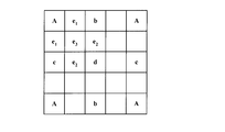
- FIG. 22 is an explanatory diagram illustrating a luminance signal interpolation process in motion compensation prediction.
- A is a pixel signal at an integer pixel position
- b, c, and d are pixel signals at a decimal pixel position with 1/2 pixel accuracy
- e 1 , e 2 , and e 3 are decimal pixel positions with 1/4 pixel accuracy.
- the pixel signal b is generated by applying a 6-tap filter to pixels at integer pixel positions in the horizontal direction.
- the pixel signal c is generated by applying a 6-tap filter to pixels at integer pixel positions in the vertical direction.
- the pixel signal d is generated by applying a 6-tap filter to a pixel at a decimal pixel position with 1/2 pixel accuracy in the horizontal or vertical direction.
- the 6-tap filter coefficient is represented by [1, -5, 20, 20, -5, 1] / 32.
- the pixel signals e 1 , e 2 , and e 3 are generated by applying a 2-tap filter [1, 1] / 2 to the pixels at neighboring integer pixel positions or decimal pixel positions, respectively.
- a picture encoded with only intra MB is called an I picture.
- a picture coded including not only an intra MB but also an inter MB is called a P picture.
- a picture that is encoded including inter MBs that use two reference pictures at the same time as well as one reference picture for inter prediction is called a B picture.
- the reference picture of the inter prediction signal with respect to the encoding target picture of the encoding target block is the forward prediction for the past inter prediction
- the reference picture of the inter prediction signal for the encoding target picture of the encoding target block Inter-prediction in which the direction of the future is called backward prediction, and inter-prediction using two reference pictures including the past and the future at the same time is called bidirectional prediction.
- the inter prediction direction is a prediction parameter for inter prediction.
- the predictor 105 compares the input video signal and the prediction signal in accordance with an instruction from the encoding controller 108, and determines a prediction parameter that minimizes the energy of the prediction error image block.
- the encoding controller 108 supplies the determined prediction parameter to the entropy encoder 102.
- the transform / quantizer 101 performs frequency conversion on the prediction error image to obtain a frequency conversion coefficient.
- the transform / quantizer 101 quantizes the frequency transform coefficient with a predetermined quantization step width Qs.
- the quantized frequency transform coefficient is referred to as a transform quantization value.
- the entropy encoder 102 entropy encodes the prediction parameter and the transform quantization value.
- the prediction parameter is information related to MB and block prediction, such as the above-described prediction mode (intra prediction, inter prediction), intra prediction block size, intra prediction direction, inter prediction block size, and motion vector.
- the inverse transform / inverse quantizer 103 inversely quantizes the transform quantization value with the quantization step width Qs. Further, the inverse transform / inverse quantizer 103 performs inverse frequency transform on the frequency transform coefficient obtained by inverse quantization. The reconstructed prediction error image subjected to the inverse frequency conversion is supplied with the prediction signal and supplied to the buffer 104.
- the buffer 104 stores the supplied reconstructed image.
- a reconstructed image for one frame is called a reconstructed picture.
- the multiplexer 106 multiplexes and outputs the output data of the entropy encoder 102 and the encoding parameter.
- the multiplexer 106 in the video encoding device Based on the above-described operation, the multiplexer 106 in the video encoding device generates a bit stream.
- Non-Patent Document 1 The video decoding device described in Non-Patent Document 1 is configured as shown in FIG.
- the video decoding apparatus shown in FIG. 23 is referred to as a general video decoding apparatus.
- the video decoding apparatus shown in FIG. 23 includes a demultiplexer 201, an entropy decoder 202, an inverse transform / inverse quantizer 203, a predictor 204, and a buffer 205.
- the demultiplexer 201 demultiplexes the input bit stream and extracts an entropy-encoded video bit stream.
- the entropy decoder 202 entropy decodes the video bitstream.
- the entropy decoder 202 entropy-decodes MB and block prediction parameters and transform quantization values, and supplies them to the inverse transform / inverse quantizer 203 and the predictor 204.
- the inverse transform / inverse quantizer 203 inversely quantizes the transform quantization value with the quantization step width. Further, the inverse transform / inverse quantizer 203 performs inverse frequency transform on the frequency transform coefficient obtained by inverse quantization.
- the predictor 204 After the inverse frequency conversion, the predictor 204 generates a prediction signal using the reconstructed picture image stored in the buffer 205 based on the entropy-decoded MB and block prediction parameters.
- the reconstructed prediction error image subjected to the inverse frequency transform by the inverse transform / inverse quantizer 203 is added with the prediction signal supplied from the predictor 204 and is supplied to the buffer 205 as a reconstructed image.
- the reconstructed picture stored in the buffer 205 is output as a decoded image (decoded video).
- a general video decoding device Based on the above-described operation, a general video decoding device generates a decoded image.
- Non-Patent Document 2 discloses a Test Model Consideration method (TMuC method). Unlike the method disclosed in Non-Patent Document 1, the TMuC method uses a coding unit (Coding Tree Block (CTB)) having a hierarchical structure shown in FIG. In this specification, a block of CTB is called Coding Unit (CU: Coding Unit).
- CTB Coding Tree Block
- PU Prediction Unit
- FIG. 25 a concept of Prediction Unit (PU) (see FIG. 25) is introduced as a prediction unit for a CU.
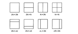
- PU is a basic unit of prediction, and is shown in FIG. 25, 8 types ⁇ 2N ⁇ 2N, 2N ⁇ N, N ⁇ 2N, N ⁇ N, 2N ⁇ nU, 2N ⁇ nD, nL ⁇ 2N, nR ⁇ 2N ⁇ .
- the PU partition type is defined.
- a PU using inter prediction is called an inter PU
- a PU using intra prediction is called an intra PU.
- a PU partition in which inter prediction is used is called an inter PU partition
- a PU partition in which intra prediction is used is called an intra PU partition.
- the intra PU partition supports only 2N ⁇ 2N and N ⁇ N squares among the shapes shown in FIG.
- the lengths of one side of CU and PU are referred to as CU size and PU size, respectively.
- a filter with a maximum of 12 taps can be used to obtain a predicted image with decimal precision.
- the relationship between the pixel position and the filter coefficient is as follows.
- a and E are pixels at integer pixel positions.
- b is a pixel at the 1/4 pixel position
- c is a pixel at the 1/2 pixel position
- d is a pixel at the 3/4 pixel position. The same applies to the vertical direction.
- the pixel b or pixel c shown in FIG. 22 is generated by applying the horizontal or vertical 1 ⁇ 2 pixel position filter once. Pixels e 1 is produced by applying one filter for quarter-pixel positions.
- the syntax indicating the PU partition type in the PU headers of the CUs of all hierarchies is intra_split_flag for intra prediction and inter_partitioning_idc for inter prediction) Embedded in the output bitstream.
- intra_split_flag syntax is referred to as intra PU partition type syntax
- inter_partitioning_idc syntax is referred to as inter PU partition type syntax.
- TMuC TMuC
- the size of the inter PU partition is smaller, there is a problem that memory access to the reference picture increases and the memory bandwidth is compressed.
- a fractional pixel is generated using a 12-tap filter, so that the memory band is further pressed.
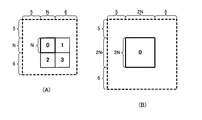
- FIG. 28 is an explanatory diagram for explaining a memory access area when a 12-tap filter is used.
- FIG. 28A shows the memory access area of one inter PU partition when the N ⁇ N PU partition type is selected
- FIG. 28B shows the case when the 2N ⁇ 2N inter PU partition type is selected. Represents a memory access area.
- the memory access amount is about 2.5 times.
- An object of the present invention is to reduce the memory bandwidth per predetermined area.
- a video encoding apparatus is a video encoding apparatus that performs video encoding using inter prediction, and is included in the maximum number of motion vectors allowed for an image block having a predetermined area and the image block having a predetermined area.
- An encoding control means is provided for controlling the inter PU partition type of the encoding target CU based on the number of motion vectors of the encoded image block.
- a video decoding apparatus is a video decoding apparatus that performs video decoding using inter prediction, and the maximum number of motion vectors allowed for an image block having a predetermined area and a decoded image included in the image block having a predetermined area.
- Decoding control means for controlling the inter PU partition type of the decoding target CU based on the number of block motion vectors is provided.
- the video encoding method according to the present invention is a video encoding method that performs video encoding using inter prediction, and is included in the maximum number of motion vectors allowed for an image block having a predetermined area and the image block having a predetermined area.
- the inter PU partition type of the CU to be encoded is controlled based on the number of motion vectors of the encoded image block.
- a video decoding method is a video decoding method that performs video decoding using inter prediction, and the maximum number of motion vectors allowed for an image block having a predetermined area and a decoded image included in the image block having a predetermined area.
- the inter-PU partition type of the decoding target CU is controlled based on the number of motion vectors of the block.
- a video encoding program allows a computer that performs video encoding using inter prediction to have a maximum number of motion vectors allowed for an image block of a predetermined area and an encoded image block included in the image block of a predetermined area. Based on the number of motion vectors, a process for controlling the inter-PU partition type of the CU to be encoded is executed.
- a video decoding program allows a computer that performs video decoding using inter prediction to have a maximum number of motion vectors allowed for an image block having a predetermined area and a motion vector of a decoded image block included in the image block having a predetermined area. And a process for controlling the inter-PU partition type of the decoding target CU based on the number of.
- the memory band per predetermined area can be reduced by limiting the usable inter PU partitions based on the number of motion vectors of the encoded image block included in the image block of the predetermined area.
- the memory bandwidth per predetermined area can be reduced by limiting the inter prediction direction based on the number of motion vectors of the encoded image block included in the image block of the predetermined area.
- an inter-PU partition of an encoding target CU based on the number of motion vectors of an encoded image block included in an image block having a predetermined area, an inter-PU partition of an encoding target CU, and The problem is solved by limiting the inter prediction direction.
- the problem is achieved by restricting inter PU partition type candidates and inter prediction direction candidates based on the number of motion vectors of an encoded image block included in an image block of a predetermined area. Resolve.
- the problem is solved by limiting inter-PU partition type syntax transmission of the PU header. According to the above example of the present invention, it is possible to suppress the memory band while improving the quality of the compressed video by suppressing the rate of the number of bits of the inter PU partition type syntax included in the bitstream.
- the predetermined area means, for example, one LCU or a plurality of continuous LCUs.
- Embodiment 1 based on the maximum number of motion vectors allowed for an image block having a predetermined area (predetermined region in an image) and the number of motion vectors of an encoded image block included in the image block having the predetermined area.
- numSucLcu LCUs one or more LCUs that are continuous in a predetermined area
- maxNumMV the maximum number of motion vectors allowed per predetermined area
- the number is currNumMV.
- the video encoding apparatus of the present embodiment is similar to the general video encoding apparatus shown in FIG. 17 in that a transform / quantizer 101, an entropy encoder 102, an inverse transform / An inverse quantizer 103, a buffer 104, a predictor 105, a multiplexer 106, and an encoding controller 107 are provided.
- NumSucLcu and maxNumMV are supplied to the encoding controller 107. Furthermore, numSucLcu and maxNumMV are also supplied to the multiplexer 106 in order to signal numSucLcu and maxNumMV to the video decoding apparatus.
- the coding controller 107 causes the predictor 105 to calculate the cost (Rate-Distortion cost: RD cost) calculated from the coding distortion (energy of the error image of the input signal and the reconstructed picture) and the generated bit amount.
- the encoding controller 107 determines the CU partition shape (the partition shape determined by split_coding_unit_flag as shown in FIG. 24) and the prediction parameter of each CU that minimize the RD cost.
- the encoding controller 107 supplies the determined split_coding_unit_flag and the prediction parameter of each CU to the predictor 105 and the entropy encoder 102.
- the prediction parameter is information related to prediction of the encoding target CU, such as a prediction mode (pred_mode), an intra PU partition type (intra_split_flag), an intra prediction direction, an inter PU partition type (inter_partitioning_idc), and a motion vector.
- pred_mode a prediction mode
- intra_split_flag an intra PU partition type
- intra_partitioning_idc an intra prediction direction
- motion vector a motion vector.
- the encoding controller 107 of this embodiment controls the PU partition type based on numSucLcu and maxNumMV as an example.
- the encoding controller 107 of the present embodiment sets the optimal PU partition type as a prediction parameter as intra prediction ⁇ 2N ⁇ 2N, N ⁇ N ⁇ and a total of 10 types of inter prediction. Select from.
- the encoding controller 107 sets the optimal PU partition type as a prediction parameter to intra prediction ⁇ 2N ⁇ 2N, N ⁇ N ⁇ , inter prediction ⁇ 2N ⁇ 2N, 2N ⁇ N.
- the encoding controller 107 sets three types of PU partition types, which are optimal as prediction parameters, intra prediction ⁇ 2N ⁇ 2N, N ⁇ N ⁇ and inter prediction ⁇ 2N ⁇ 2N ⁇ . Select from.
- maxNumMV-currNumMV ⁇ 1 the encoding controller 107 selects an optimal PU partition type as a prediction parameter from two types of intra prediction ⁇ 2N ⁇ 2N, N ⁇ N ⁇ .
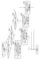
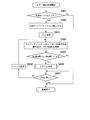
- FIG. 2 is a flowchart showing the operation of the encoding controller 107 of the present embodiment regarding the prediction parameter determination of each CU.
- the encoding controller 107 determines PU partition candidates in step S101.
- the encoding controller 107 determines an inter prediction direction candidate.
- a prediction parameter is determined based on the RD cost.
- the encoding controller 107 updates currNumMV from the PU partition type and the inter prediction direction determined in the processes of steps S102 and S103.
- FIG. 3 is a flowchart showing the operation of determining PU partition type candidates in step S101 in FIG.
- the PU partition type candidate is converted to intra prediction ⁇ 2N ⁇ 2N, N ⁇ N ⁇ and 10 types of inter prediction all sets in step S202. Set.
- a PU partition type candidate are set to nine types of intra prediction ⁇ 2N ⁇ 2N, N ⁇ N ⁇ , inter prediction ⁇ 2N ⁇ 2N, 2N ⁇ N, N ⁇ 2N, 2N ⁇ nU, 2N ⁇ nD, nL ⁇ 2N, nR ⁇ 2N ⁇ .
- step S205 a PU partition type candidate.
- the encoding controller 107 sets PU partition type candidates as two types of intra prediction ⁇ 2N ⁇ 2N, N ⁇ N ⁇ .
- FIG. 4 is a flowchart showing an operation of determining inter prediction direction candidates in step S102 of FIG.
- the index of each partition of the PU is represented by i
- the number of partitions is represented by m.
- i the index of each partition of the PU
- m 4
- the index i takes values of 1, 2, 3, and 4.
- step S302 the encoding controller 107 sets a variable i representing the index of the PU partition to 1.
- step S303 when it is determined in step S303 that maxNumMV ⁇ k-(mi) ⁇ 1, the encoding controller 107 selects a candidate for the inter prediction direction of partition i ⁇ previous, subsequent in step S306. ⁇ .
- step S308 if i is equal to m, the process is terminated.
- the predictor 105 selects a prediction signal corresponding to the prediction parameter of each CU determined by the encoding controller 107.
- the input video of each CU having the shape determined by the encoding controller 107 is a prediction error image obtained by subtracting the prediction signal supplied from the predictor 105 and is input to the transform / quantizer 101.
- the transform / quantizer 101 performs frequency conversion on the prediction error image to obtain a frequency conversion coefficient.
- the transform / quantizer 101 quantizes the frequency transform coefficient with the quantization step width Qs to obtain a transform quantized value.
- the entropy encoder 102 entropy-encodes the split_coding_unit_flag (see FIG. 24) supplied from the encoding controller 107, the prediction parameter, and the transform quantization value supplied from the transform / quantizer 101.
- the inverse transform / inverse quantizer 103 inversely quantizes the transform quantization value with the quantization step width Qs. Further, the inverse transform / inverse quantizer 103 performs inverse frequency transform on the frequency transform coefficient obtained by inverse quantization. The reconstructed prediction error image subjected to the inverse frequency conversion is supplied with the prediction signal and supplied to the buffer 104.
- the multiplexer 106 multiplexes and outputs information on the predetermined area, information on the number of motion vectors allowed per predetermined area, and output data of the entropy encoder 103.
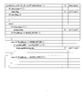
- the multiplexer 106 as represented in the list shown in FIG. 5, is num_successive_largest_coding_unit (the value of numSucLcu in this embodiment)
- the max_num_motion_vector syntax (in this embodiment, the value of maxNumMV) is multiplexed.
- the video encoding device of the invention Based on the above-described operation, the video encoding device of the invention generates a bitstream.
- the video encoding apparatus uses the maximum number of motion vectors allowed for an image block having a predetermined area so that more motion vectors than the maximum number of motion vectors allowed for an image block having a predetermined area within the predetermined area are not used.
- the encoding control means controls the inter PU partition type and inter prediction direction of the encoding target CU based on the number and the number of motion vectors of the encoded image block included in the image block having the predetermined area. .
- the video encoding device inter-PU partition type of the PU header layer of the encoding target CU Entropy encoding is performed with the syntax set to a predetermined inter-PU partition type.
- the memory bandwidth is reduced by preventing the use of more motion vectors than the maximum number of motion vectors within a predetermined area.
- the code amount of the PU header occupying the bitstream And the quality of the video is improved.
- the occurrence probability of each inter PU partition type is biased and the entropy is reduced, so that the efficiency of entropy coding is increased. Therefore, the quality of the compressed video can be maintained while reducing the memory bandwidth.
- the video encoding apparatus embeds information on a predetermined area and information on the maximum number of motion vectors allowed for an image block having a predetermined area in a bitstream. Therefore, the information regarding the predetermined area and the maximum number of motion vectors allowed for the image block of the predetermined area are signaled to the video decoding apparatus, and the interoperability between the video encoding apparatus and the video decoding apparatus can be improved. it can.
- Embodiment 2 The video encoding apparatus according to the second embodiment controls the inter PU partition type and the inter prediction direction based on a predetermined area set externally and the maximum number of motion vectors allowed for an image block of the predetermined area, Encoding control means for controlling entropy encoding of inter PU partition type syntax based on the number of motion vectors of an encoded image block included in an image block of a predetermined area, and a motion vector allowed for an image block of a predetermined area Information about a predetermined area, information on the maximum number of motion vectors allowed for an image block of a predetermined area, and a predetermined area for signaling information on the maximum number of motion vectors and the number of motion vectors allowed for the predetermined area to the video decoding apparatus. Information on the number of motion vectors allowed Comprising means for embedding in the stream.
- numSucLcu LCUs that are continuous in a predetermined area, the maximum number of motion vectors allowed for an image block of a predetermined area is maxNumMV, and the number of motion vectors of an encoded image block included in an image block within the predetermined area Is currNumMV.
- the configuration of the video encoding device of the present embodiment is the same as the configuration of the video encoding device of the first embodiment shown in FIG.
- numSucLcu maxNumMV is supplied to the encoding controller 107. Furthermore, numSucLcu and maxNumMV are also supplied to the multiplexer 106 in order to signal numSucLcu and maxNumMV to the video decoding apparatus.
- the coding controller 107 causes the predictor 105 to calculate the RD cost calculated from the coding distortion (energy of the error image of the input signal and the reconstructed picture) and the generated bit amount.
- the encoding controller 107 determines the CU partition shape (the partition shape determined by split_coding_unit_flag as shown in FIG. 24) and the prediction parameter of each CU that minimize the RD cost.
- the encoding controller 107 supplies the determined split_coding_unit_flag and the prediction parameter of each CU to the predictor 105 and the entropy encoder 102.
- the prediction parameter is information related to prediction of the encoding target CU, such as a prediction mode (pred_mode), an intra PU partition type (intra_split_flag), an intra prediction direction, an inter PU partition type (inter_partitioning_idc), and a motion vector.
- pred_mode a prediction mode
- intra_split_flag an intra PU partition type
- intra_partitioning_idc an intra prediction direction
- motion vector a motion vector.
- the encoding controller 107 of this embodiment determines PU partition type and inter prediction direction candidates as in the first embodiment.
- the encoding controller 107 determines a prediction parameter based on the RD cost using the determined PU partition and inter prediction direction candidates.
- the encoding controller 107 does not entropy-encode inter_partitioning_idc so that it is not entropy-encoded when the prediction mode of the encoding target CU is inter prediction and maxNumMV-currNumMV ⁇ 1. 102 is controlled.
- the predictor 105 selects a prediction signal corresponding to the prediction parameter of each CU determined by the encoding controller 107.
- the input video of each CU having the shape determined by the encoding controller 107 is a prediction error image obtained by subtracting the prediction signal supplied from the predictor 105 and is input to the transform / quantizer 101.
- the transform / quantizer 101 performs frequency conversion on the prediction error image to obtain a frequency conversion coefficient.
- the transform / quantizer 101 quantizes the frequency transform coefficient with the quantization step width Qs to obtain a transform quantized value.
- the entropy encoder 102 entropy-encodes the split_coding_unit_flag (see FIG. 24) supplied from the encoding controller 107, the prediction parameter, and the transform quantization value supplied from the transform / quantizer 101.
- the inverse transform / inverse quantizer 103 inversely quantizes the transform quantization value with the quantization step width Qs. Further, the inverse transform / inverse quantizer 103 performs inverse frequency transform on the frequency transform coefficient obtained by inverse quantization. The reconstructed prediction error image subjected to the inverse frequency conversion is supplied with the prediction signal and supplied to the buffer 104.
- the multiplexer 106 multiplexes and outputs information on the predetermined area, information on the number of motion vectors allowed per predetermined area, and output data of the entropy encoder 103.
- the multiplexer 106 as represented in the list shown in FIG. 5, is num_successive_largest_coding_unit (the value of numSucLcu in this embodiment)
- the max_num_motion_vector syntax (in this embodiment, the value of maxNumMV) is multiplexed.
- the video encoding device of the invention Based on the above-described operation, the video encoding device of the invention generates a bitstream.
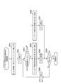
- inter-PU partition type syntax writing which is a feature of this embodiment, will be described with reference to the flowchart of FIG.
- the entropy encoder 102 entropy-encodes split_coding_unit_flag in step S401.
- step S402 the entropy encoder 102 performs entropy encoding on the prediction mode. That is, the pred_mode syntax is entropy encoded.
- step S403 If it is determined in step S403 that the prediction mode of the encoding target CU is inter prediction, and if it is determined in step S404 that maxNumMV ⁇ currNumMV ⁇ 1, the encoding controller 107 includes an entropy encoder. Control is performed so as to skip the entropy coding of the inter_partitioning_idc syntax in 102.
- step S403 If it is determined in step S403 that the CU to be encoded is intra prediction, or if it is determined in step S404 that maxNumMV ⁇ currNumMV ⁇ 2, the encoding controller 107 in step S405 determines the entropy code.
- the encoder 102 performs entropy encoding on the PU partition type information of the encoding target CU.
- the pred_mode syntax and the inter_partitioning_idc syntax described above are signaled as shown in the list shown in FIG. 7 according to the notation of 4.1.10 Prediction unit syntax of Non-Patent Document 2.
- the feature of this embodiment is that if the number is two or more, the inter_partitioning_idc syntax is signaled.
- the video encoding apparatus is based on the number of motion vectors allowed for a predetermined area based on the maximum number of motion vectors allowed for an image block having a predetermined area (in this embodiment, the maximum number of motion vectors ⁇ 1). And an encoding control means for controlling the inter PU partition type and the inter prediction direction.
- the video encoding device does not transmit unnecessary inter-PU partition type information, thereby reducing the bit rate of the inter-PU partition type included in the bitstream, and reducing the memory bandwidth and improving the quality of the compressed video. Can hold.
- the video encoding apparatus also allows information regarding externally set predetermined areas and motions allowed for image blocks having a predetermined area so that the inter-PU partition type syntax can be read from the bitstream in the same manner for video decoding.
- a means for embedding information on the maximum number of vectors and the number of motion vectors allowed for a predetermined area in the bit stream is provided. Therefore, the interoperability between the video encoding device and the video decoding device can be improved.
- the video encoding device of the present embodiment further includes the number of motion vectors of encoded image blocks included in an image block of a predetermined area so as to reduce the number of inter-PU partition type syntax signaled.
- the number of motion vectors subtracted by 1 from the maximum number of motion vectors is less than the number of motion vectors less than 1 subtracted from the maximum number of motion vectors without entropy encoding the inter PU partition type syntax of the PU header layer of the CU to be encoded Only to control the inter-PU partition type syntax.
- FIG. The video decoding device according to the third embodiment decodes the bitstream generated by the video encoding device according to the second embodiment.
- the video decoding apparatus includes a unit for demultiplexing information on a predetermined area multiplexed in a bitstream and information on the number of motion vectors allowed for an image block having a predetermined area, and an image block having a predetermined area. It is characterized by comprising reading means for reading the inter PU partition type from the bit stream based on the number of motion vectors of the encoded image block included.
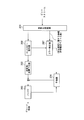
- the video decoding apparatus includes a demultiplexer 201, an entropy decoder 202, an inverse transform / inverse quantizer 203, a predictor 204, a buffer 205, and a decoding controller 206. .
- the demultiplexer 201 demultiplexes the input bitstream, and extracts information on a predetermined area, information on the number of motion vectors allowed for an image block having a predetermined area, and an entropy-coded video bitstream. .
- the demultiplexer 201 demultiplexes the num_successive_largest_coding_unit syntax and the max_num_motion_vector syntax in the sequence parameters as shown in the list shown in FIG.
- the demultiplexer 201 supplies the information related to the predetermined area and the maximum number of motion vectors allowed for the image block of the predetermined area to the decoding controller 206.
- the entropy decoder 202 entropy decodes the video bitstream.
- the entropy decoder 202 supplies the transform quantization value subjected to entropy decoding to the inverse transform / inverse quantizer 203.
- the entropy decoder 202 supplies the entropy-decoded split_coding_unit_flag and the prediction parameter to the decoding controller 206.
- the decoding controller 206 of the present embodiment has the prediction mode of the decoding target CU being inter prediction, and maxNumMV ⁇
- the entropy decoder 202 is caused to skip the entropy decoding of the inter PU partition type syntax of the decoding target CU.
- the demultiplexer 201 sets the inter PU partition type of the decoding target CU to 2N ⁇ 2N.
- currNumMV is updated based on the inter prediction direction of each partition decoded following the inter PU partition type.
- the inverse transform / inverse quantizer 203 inversely quantizes the transform quantization values of luminance and color difference with the quantization step width. Further, the inverse transform / inverse quantizer 203 performs inverse frequency transform on the frequency transform coefficient obtained by inverse quantization.
- the predictor 204 After the inverse frequency conversion, the predictor 204 generates a prediction signal using the reconstructed picture image stored in the buffer 205 based on the prediction parameter supplied from the decoding controller 206.
- the reconstructed prediction error image subjected to inverse frequency transform by the inverse transform / inverse quantizer 203 is added with the prediction signal supplied from the predictor 204 and supplied to the buffer 205 as a reconstructed picture.
- the reconstructed picture stored in the buffer 205 is output as a decoded image.
- the video decoding apparatus Based on the above-described operation, the video decoding apparatus according to the present embodiment generates a decoded image.
- the entropy decoder 202 entropy-decodes the split_coding_unit_flag in step S501 to determine the CU size.
- step S502 the entropy decoder 202 entropy decodes the prediction mode. That is, the pred_mode syntax is entropy decoded.
- step S503 When it is determined in step S503 that the prediction mode is intra prediction, or when it is determined in step S504 that maxNumMV ⁇ currNumMV ⁇ 2, the decoding controller 206 in step S506, the entropy decoder 204. Is subjected to entropy decoding, and the PU partition type of the CU is set as the PU partition type of the entropy decoding result.
- the video encoding apparatus includes information regarding the predetermined area (num_successive_largest_coding_unit) used in the first embodiment and information regarding the number of motion vectors allowed per predetermined area (max_num_motion_vector).
- the predetermined area number_successive_largest_coding_unit
- max_num_motion_vector information regarding the number of motion vectors allowed per predetermined area
- multiplexing can be performed in a picture parameter set or a slice header.
- FIG. 10 is an explanatory diagram of a list showing information on a predetermined area and information on the maximum number of motion vectors allowed for an image block having a predetermined area in the picture parameter set.
- FIG. 11 is an explanatory diagram of a list showing information on a predetermined area and information on the number of motion vectors allowed for an image block having a predetermined area in a slice header.
- the video decoding apparatus of the above-described invention can demultiplex the num_successive_largest_coding_unit syntax and the max_num_motion_vector syntax from the picture parameter set and slice header.
- the video decoding apparatus allows the maximum number of motion vectors allowed for an image block having a predetermined area so that a motion vector larger than the maximum number of motion vectors allowed for an image block having a predetermined area within the predetermined area is not used.
- decoding control means for controlling the inter PU partition type and inter prediction direction of the decoding target CU based on the number of motion vectors of the encoded image block included in the image block of the predetermined area.
- the memory bandwidth is reduced by preventing the use of more motion vectors than the maximum number of motion vectors within a predetermined area.
- Embodiment 4 The video decoding apparatus according to the fourth embodiment decodes the bitstream generated by the video encoding apparatus according to the first embodiment.
- the video decoding apparatus includes a unit for demultiplexing information on a predetermined area multiplexed in a bitstream and information on the maximum number of motion vectors allowed for an image block of the predetermined area, and the predetermined area It is characterized by comprising error detection means for detecting an error in the access unit of the bitstream including the decoding target CU based on the number of motion vectors of the encoded image block included in the image block.
- the access unit is a unit for storing encoded data for one picture as defined in 3.1 [access] unit of Non-Patent Document 1.
- An error means a violation of a constraint based on the number of motion vectors allowed per predetermined area.
- the video decoding apparatus includes a demultiplexer 201, an entropy decoder 202, an inverse transform / inverse quantizer 203, a predictor 204, a buffer 205, and an error detector 207. .
- the demultiplexer 201 operates in the same manner as the demultiplexer 201 in the third embodiment, demultiplexes the input bit stream, and moves the information regarding a predetermined area and an image block having a predetermined area. Information on the maximum number of vectors and an entropy-encoded video bitstream are extracted.
- the demultiplexer 201 demultiplexes the num_successive_largest_coding_unit syntax and the max_num_motion_vector syntax in the sequence parameters as shown in the list shown in FIG.
- the demultiplexer 201 supplies the error detector 207 with information on a predetermined area and the maximum number of motion vectors allowed for an image block of the predetermined area.
- the entropy decoder 202 entropy decodes the video bitstream.
- the entropy decoder 202 supplies the transform quantization value subjected to entropy decoding to the inverse transform / inverse quantizer 203.
- the entropy decoder 202 supplies the entropy-decoded split_coding_unit_flag and the prediction parameter to the error detector 207.
- the error detector 207 detects error of the prediction parameter supplied from the entropy decoder 201 based on the information regarding the predetermined area supplied from the demultiplexer 201 and the maximum number of motion vectors allowed for the image block of the predetermined area. To supply the prediction parameters to the predictor 204. The error detection operation will be described later. Note that the error detector 207 also serves as the decoding controller 206 in the third embodiment.
- the inverse transform / inverse quantizer 203 operates in the same manner as the inverse transform / inverse quantizer 203 in the third embodiment.
- the predictor 204 generates a prediction signal using the reconstructed picture image stored in the buffer 205 based on the prediction parameter supplied from the error detector 207.
- the buffer 205 operates in the same manner as the buffer 205 in the third embodiment.
- the video decoding apparatus Based on the above-described operation, the video decoding apparatus according to the present embodiment generates a decoded image.
- step S601 when the error detector 207 determines that the prediction mode of the PU of the decoding target CU is intra, the process ends.
- step S602 the error detector 207 sets m to the number of PU partitions of the decoding target CU.
- step S605 the error detector 207 determines that there is an error in step S606 if the number of motion vectors (maxNumMV-currNumMV) that can be used in the remaining inter-PUs is less than the number of remaining partitions (mi). It is determined that the error is reported to the outside. For example, the address of the CU in which an error has occurred is output.
- the error detector 207 detects an error in the access unit of the bit stream including the decoding target CU.
- the video encoding device and video decoding device of the invention described above controlled the inter PU partition of the encoding target CU based on the maximum number of motion vectors allowed for an image block of a predetermined area. It is also possible to perform control using the maximum number of inter PU partitions allowed for an image block of a predetermined area or the maximum amount of memory access allowed for an image block of a predetermined area.
- each of the above embodiments can be configured by hardware, it can also be realized by a computer program.
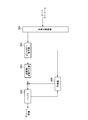
- the information processing system shown in FIG. 14 includes a processor 1001, a program memory 1002, a storage medium 1003 for storing video data, and a storage medium 1004 for storing a bitstream.
- the storage medium 1003 and the storage medium 1004 may be separate storage media, or may be storage areas composed of the same storage medium.
- a magnetic storage medium such as a hard disk can be used as the storage medium.
- the program memory 1002 stores a program for realizing the function of each block (excluding the buffer block) shown in each of FIG. 1, FIG. 8, and FIG. Is done.
- the processor 1001 implements the functions of the video encoding device or the video decoding device shown in FIGS. 1, 8, and 12 by executing processing according to the program stored in the program memory 1002. .
- FIG. 15 is a block diagram showing the main part of the video encoding apparatus according to the present invention.
- the video encoding apparatus according to the present invention is a video encoding apparatus that performs video encoding using inter prediction, and the maximum number (PA) of motion vectors allowed for an image block of a predetermined area.
- PB motion vectors
- FIG. 16 is a block diagram showing the main part of the video decoding apparatus according to the present invention.
- the video decoding apparatus according to the present invention is a video decoding apparatus that performs video decoding using inter prediction, and the maximum number (PA) of motion vectors allowed for an image block of a predetermined area, and a predetermined number.
- Decoding control means 21 for controlling the inter PU partition type of the decoding target CU based on the number of motion vectors (PB) of the decoded image blocks included in the image block of the area (for example, shown in FIGS. 8 and 12)
- PB motion vectors
- a decoding controller 207 A decoding controller 207).
- DESCRIPTION OF SYMBOLS 11 Coding control means 21 Decoding control means 101 Transformer / quantizer 102 Entropy coder 103 Inverse transform / dequantizer 104 Buffer 105 Predictor 106 Multiplexer 107,108 Encoding controller 201 Demultiplexer 202 Entropy decoder 203 Inverse transform / inverse quantizer 204 Predictor 205 Buffer 206 Decoding controller 207 Error detector 1001 Processor 1002 Program memory 1003 Storage medium 1004 Storage medium
Landscapes
- Engineering & Computer Science (AREA)
- Multimedia (AREA)
- Signal Processing (AREA)
- Compression Or Coding Systems Of Tv Signals (AREA)
- Two-Way Televisions, Distribution Of Moving Picture Or The Like (AREA)
Abstract
Description

第1の実施形態では、所定面積(画像における所定領域)の画像ブロックに許容する動きベクトルの最大本数と上記の所定面積の画像ブロックに含まれる符号化済み画像ブロックの動きベクトルの本数とに基づいて、インターPUパーティションタイプとインター予測方向を制御する符号化制御手段、及び、所定面積の画像ブロックに許容する動きベクトルの最大本数に関する情報を映像復号装置にシグナリングするための、所定面積に関する情報と所定面積の画像ブロックに許容する動きベクトルの最大本数に関する情報をビットストリームに埋め込む手段を備える映像符号化装置を示す。
第2の実施形態の映像符号化装置は、外部設定される所定面積と所定面積の画像ブロックに許容する動きベクトルの最大本数に基づいて、インターPUパーティションタイプとインター予測方向を制御し、上記の所定面積の画像ブロックに含まれる符号化済み画像ブロックの動きベクトルの本数に基づいてインターPUパーティションタイプシンタクスのエントロピー符号化を制御する符号化制御手段、及び、所定面積の画像ブロックに許容する動きベクトルの最大本数と所定面積に許容する動きベクトルの本数とに関する情報を映像復号装置にシグナリングするための、所定面積に関する情報と所定面積の画像ブロックに許容する動きベクトルの最大本数に関する情報と所定面積あたりに許容する動きベクトルの本数に関する情報とをビットストリームに埋め込む手段を備える。
第3の実施形態の映像復号装置は、第2の実施形態の映像符号化装置が生成したビットストリームを復号する。
第4の実施形態の映像復号装置は、第1の実施形態の映像符号化装置が生成したビットストリームを復号する。
21 復号制御手段
101 変換/量子化器
102 エントロピー符号化器
103 逆変換/逆量子化器
104 バッファ
105 予測器
106 多重化器
107,108 符号化制御器
201 多重化解除器
202 エントロピー復号器
203 逆変換/逆量子化器
204 予測器
205 バッファ
206 復号制御器
207 エラー検出器
1001 プロセッサ
1002 プログラムメモリ
1003 記憶媒体
1004 記憶媒体
Claims (30)
- インター予測を用いて映像符号化を行う映像符号化装置であって、
所定面積の画像ブロックに許容する動きベクトルの最大本数と、前記所定面積の画像ブロックに含まれる符号化済み画像ブロックの動きベクトルの本数とに基づいて、符号化対象CUのインターPUパーティションタイプを制御する符号化制御手段を備えることを特徴とする映像符号化装置。 - 前記符号化制御手段は、符号化対象CUのインターPUパーティションタイプのインター予測方向も制御する請求項1記載の映像符号化装置。
- 前記所定面積を示すデータ、及び前記動きベクトルの最大本数をビットストリームに多重化する多重化手段を備える請求項1又は請求項2記載の映像符号化装置。
- エントロピー符号化手段を備え、
前記符号化制御手段は、前記所定面積の画像ブロックに含まれる符号化済み画像ブロックの動きベクトルの本数が、前記動きベクトルの最大本数未満のときに、前記エントロピー符号化手段に、該符号化対象CUのPUヘッダレイヤのインターPUパーティションタイプシンタクスを所定のインターPUパーティションタイプに設定してエントロピー符号化させる請求項1から請求項3のうちのいずれか1項に記載の映像符号化装置。 - エントロピー符号化手段を備え、
前記符号化制御手段は、前記所定面積の画像ブロックに含まれる符号化済み画像ブロックの動きベクトルの本数が、前記動きベクトルの最大本数から1減じた本数以上であるときには、前記エントロピー符号化手段に、該符号化対象CUのPUヘッダレイヤのインターPUパーティションタイプシンタクスをエントロピー符号化させず、前記動きベクトルの本数が、前記動きベクトルの最大本数から1減じた本数未満であるときに、前記エントロピー符号化手段に、該符号化対象CUのPUヘッダレイヤのインターPUパーティションタイプシンタクスをエントロピー符号化させる請求項1から請求項3のうちのいずれか1項に記載の映像符号化装置。 - インター予測を用いて映像復号を行う映像復号装置であって、
所定面積の画像ブロックに許容する動きベクトルの最大本数と、前記所定面積の画像ブロックに含まれる復号済み画像ブロックの動きベクトルの本数とに基づいて、復号対象CUのインターPUパーティションタイプを制御する復号制御手段を備えることを特徴とする映像復号装置。 - 前記復号制御手段は、復号対象CUのインターPUパーティションタイプのインター予測方向も制御する請求項6記載の映像復号装置。
- 前記所定面積を示すデータ、及び、前記動きベクトルの最大本数をビットストリームから多重化解除する多重化解除手段を備える請求項6又は請求項7記載の映像復号装置。
- エントロピー復号手段を備え、
前記復号制御手段は、前記所定面積の画像ブロックに含まれる復号済み画像ブロックの動きベクトルの本数が、前記動きベクトルの最大本数から1減じた本数以上であるときには、前記エントロピー復号手段に、該復号対象CUのPUヘッダレイヤのインターPUパーティションタイプシンタクスをエントロピー復号させず、前記動きベクトルの本数が、前記動きベクトルの最大本数未満であるときに、前記エントロピー復号手段に、該復号対象CUのPUヘッダレイヤのインターPUパーティションタイプシンタクスをエントロピー復号させる請求項6から請求項8のうちのいずれか1項に記載の映像復号装置。 - 前記復号制御手段は、前記所定面積の画像ブロックに含まれる復号済み画像ブロックの動きベクトルの本数が、前記動きベクトルの最大本数より大きいときに、該復号CUを含むビットストリームのアクセスユニットにエラーがあると判断する請求項6から請求項8のうちのいずれか1項に記載の映像復号装置。
- インター予測を用いて映像符号化を行う映像符号化方法であって、
所定面積の画像ブロックに許容する動きベクトルの最大本数と、前記所定面積の画像ブロックに含まれる符号化済み画像ブロックの動きベクトルの本数とに基づいて、符号化対象CUのインターPUパーティションタイプを制御することを特徴とする映像符号化方法。 - 符号化対象CUのインターPUパーティションタイプのインター予測方向も制御する請求項11記載の映像符号化方法。
- 前記所定面積を示すデータ、及び前記動きベクトルの最大本数をビットストリームに多重化する請求項11又は請求項12記載の映像符号化方法。
- 前記所定面積の画像ブロックに含まれる符号化済み画像ブロックの動きベクトルの本数が、前記動きベクトルの最大本数未満のときに、該符号化対象CUのPUヘッダレイヤのインターPUパーティションタイプシンタクスを所定のインターPUパーティションタイプに設定してエントロピー符号化する請求項11から請求項13のうちのいずれか1項に記載の映像符号化方法。
- 前記所定面積の画像ブロックに含まれる符号化済み画像ブロックの動きベクトルの本数が、前記動きベクトルの最大本数から1減じた本数以上であるときには、該符号化対象CUのPUヘッダレイヤのインターPUパーティションタイプシンタクスをエントロピー符号化せず、前記動きベクトルの最大本数から1減じた本数未満であるときに、該符号化対象CUのPUヘッダレイヤのインターPUパーティションタイプシンタクスをエントロピー符号化する請求項11から請求項13のうちのいずれか1項に記載の映像符号化方法。
- インター予測を用いて映像復号を行う映像復号方法であって、
所定面積の画像ブロックに許容する動きベクトルの最大本数と、前記所定面積の画像ブロックに含まれる復号済み画像ブロックの動きベクトルの本数とに基づいて、復号対象CUのインターPUパーティションタイプを制御することを特徴とする映像復号方法。 - 復号対象CUのインターPUパーティションタイプのインター予測方向も制御する請求項16記載の映像復号方法。
- 前記所定面積を示すデータ、及び、前記動きベクトルの最大本数をビットストリームから多重化解除する請求項16又は請求項17記載の映像復号方法。
- 前記所定面積の画像ブロックに含まれる復号済み画像ブロックの動きベクトルの本数が、前記動きベクトルの最大本数から1減じた本数以上であるときには、該復号対象CUのPUヘッダレイヤのインターPUパーティションタイプシンタクスをエントロピー復号せず、前記動きベクトルの最大本数未満であるときに、該復号対象CUのPUヘッダレイヤのインターPUパーティションタイプシンタクスをエントロピー復号する請求項16から請求項18のうちのいずれか1項に記載の映像復号方法。
- 前記所定面積の画像ブロックに含まれる復号済み画像ブロックの動きベクトルの本数が、前記動きベクトルの最大本数より大きいときに、該復号CUを含むビットストリームのアクセスユニットにエラーがあると判断する請求項16から請求項18のうちのいずれか1項に記載の映像復号方法。
- インター予測を用いて映像符号化を行うコンピュータに、
所定面積の画像ブロックに許容する動きベクトルの最大本数と、前記所定面積の画像ブロックに含まれる符号化済み画像ブロックの動きベクトルの本数とに基づいて、符号化対象CUのインターPUパーティションタイプを制御する処理を実行させるための映像符号化プログラム。 - コンピュータに、符号化対象CUのインターPUパーティションタイプのインター予測方向を制御する処理も実行させる請求項21記載の映像符号化プログラム。
- コンピュータに、前記所定面積を示すデータ、及び前記動きベクトルの最大本数をビットストリームに多重化する処理を実行させる請求項21又は請求項22記載の映像符号化プログラム。
- コンピュータに、前記所定面積の画像ブロックに含まれる符号化済み画像ブロックの動きベクトルの本数が、前記動きベクトルの最大本数未満のときに、該符号化対象CUのPUヘッダレイヤのインターPUパーティションタイプシンタクスを所定のインターPUパーティションタイプに設定してエントロピー符号化する処理を実行させる請求項21から請求項23のうちのいずれか1項に記載の映像符号化プログラム。
- コンピュータに、前記所定面積の画像ブロックに含まれる符号化済み画像ブロックの動きベクトルの本数が、前記動きベクトルの最大本数から1減じた本数以上であるときには、該符号化対象CUのPUヘッダレイヤのインターPUパーティションタイプシンタクスをエントロピー符号化する処理を実行させず、前記動きベクトルの最大本数から1減じた本数未満であるときに、該符号化対象CUのPUヘッダレイヤのインターPUパーティションタイプシンタクスをエントロピー符号化する処理を実行させる請求項21から請求項23のうちのいずれか1項に記載の映像符号化プログラム。
- インター予測を用いて映像復号を行うコンピュータに、
所定面積の画像ブロックに許容する動きベクトルの最大本数と、前記所定面積の画像ブロックに含まれる復号済み画像ブロックの動きベクトルの本数とに基づいて、復号対象CUのインターPUパーティションタイプを制御する処理を実行させるための映像復号プログラム。 - コンピュータに、復号対象CUのインターPUパーティションタイプのインター予測方向を制御する処理も実行させる請求項26記載の映像復号プログラム。
- コンピュータに、前記所定面積を示すデータ、及び、前記動きベクトルの最大本数をビットストリームから多重化解除する処理を実行させる請求項26又は請求項27記載の映像復号プログラム。
- コンピュータに、前記所定面積の画像ブロックに含まれる復号済み画像ブロックの動きベクトルの本数が、前記動きベクトルの最大本数から1減じた本数以上であるときには、該復号対象CUのPUヘッダレイヤのインターPUパーティションタイプシンタクスをエントロピー復号する処理を実行させず、前記動きベクトルの最大本数未満であるときに、該復号対象CUのPUヘッダレイヤのインターPUパーティションタイプシンタクスをエントロピー復号する処理を実行させる請求項26から請求項28のうちのいずれか1項に記載の映像復号プログラム。
- コンピュータに、前記所定面積の画像ブロックに含まれる復号済み画像ブロックの動きベクトルの本数が、前記動きベクトルの最大本数より大きいときに、該復号CUを含むビットストリームのアクセスユニットにエラーがあると判断する処理を実行させる請求項26から請求項28のうちのいずれか1項に記載の映像復号プログラム。
Priority Applications (17)
| Application Number | Priority Date | Filing Date | Title |
|---|---|---|---|
| BR112013017802-7A BR112013017802B1 (pt) | 2011-01-13 | 2012-01-05 | Dispositivo de decodificação de vídeo e método de decodificação de vídeo |
| BR122020018552-0A BR122020018552B1 (pt) | 2011-01-13 | 2012-01-05 | Dispositivo de decodificação de vídeo e método de decodificação de vídeo |
| PL12734382T PL2665273T3 (pl) | 2011-01-13 | 2012-01-05 | Urządzenie do dekodowania wideo, sposób dekodowania wideo i program |
| BR122020018553-8A BR122020018553B1 (pt) | 2011-01-13 | 2012-01-05 | Dispositivo de decodificação de vídeo para decodificação de vídeo usando interprevisão e método de decodificação de vídeo para decodificação de vídeo usando interprevisão |
| KR1020187010850A KR101935217B1 (ko) | 2011-01-13 | 2012-01-05 | 영상 부호화 장치 및 영상 부호화 방법 |
| KR1020157022459A KR101841334B1 (ko) | 2011-01-13 | 2012-01-05 | 영상 부호화 장치, 영상 복호 장치, 영상 부호화 방법, 영상 복호 방법 및 프로그램 |
| US13/977,756 US10841588B2 (en) | 2011-01-13 | 2012-01-05 | Video encoding device, video decoding device, video encoding method, video decoding method, and program using inter prediction |
| EP12734382.0A EP2665273B1 (en) | 2011-01-13 | 2012-01-05 | Video decoding device, video decoding method, and program |
| ES12734382T ES2900775T3 (es) | 2011-01-13 | 2012-01-05 | Dispositivo de descodificación de vídeo, método de descodificación de vídeo y programa |
| CN201280005384.5A CN103314590B (zh) | 2011-01-13 | 2012-01-05 | 视频解码设备、视频解码方法 |
| JP2012552666A JP5974899B2 (ja) | 2011-01-13 | 2012-01-05 | 映像復号装置、映像復号方法及びプログラム |
| EP21197304.5A EP3965418A1 (en) | 2011-01-13 | 2012-01-05 | Video decoding method and video decoder |
| KR1020167022895A KR101840579B1 (ko) | 2011-01-13 | 2012-01-05 | 영상 복호 장치, 영상 복호 방법 및 프로그램 |
| KR1020137016920A KR101851326B1 (ko) | 2011-01-13 | 2012-01-05 | 영상 부호화 장치, 영상 복호 장치, 영상 부호화 방법, 영상 복호 방법 및 프로그램 |
| US17/060,828 US11323720B2 (en) | 2011-01-13 | 2020-10-01 | Video encoding device, video decoding device, video encoding method, video decoding method, and program using inter prediction |
| US17/685,543 US11665352B2 (en) | 2011-01-13 | 2022-03-03 | Video encoding device, video decoding device, video encoding method, video decoding method, and program using inter prediction |
| US17/685,579 US11647205B2 (en) | 2011-01-13 | 2022-03-03 | Video encoding device, video decoding device, video encoding method, video decoding method, and program using inter prediction |
Applications Claiming Priority (2)
| Application Number | Priority Date | Filing Date | Title |
|---|---|---|---|
| JP2011004963 | 2011-01-13 | ||
| JP2011-004963 | 2011-01-13 |
Related Child Applications (2)
| Application Number | Title | Priority Date | Filing Date |
|---|---|---|---|
| US13/977,756 A-371-Of-International US10841588B2 (en) | 2011-01-13 | 2012-01-05 | Video encoding device, video decoding device, video encoding method, video decoding method, and program using inter prediction |
| US17/060,828 Continuation US11323720B2 (en) | 2011-01-13 | 2020-10-01 | Video encoding device, video decoding device, video encoding method, video decoding method, and program using inter prediction |
Publications (1)
| Publication Number | Publication Date |
|---|---|
| WO2012096146A1 true WO2012096146A1 (ja) | 2012-07-19 |
Family
ID=46507055
Family Applications (1)
| Application Number | Title | Priority Date | Filing Date |
|---|---|---|---|
| PCT/JP2012/000045 Ceased WO2012096146A1 (ja) | 2011-01-13 | 2012-01-05 | 映像符号化装置、映像復号装置、映像符号化方法、映像復号方法及びプログラム |
Country Status (9)
| Country | Link |
|---|---|
| US (4) | US10841588B2 (ja) |
| EP (2) | EP2665273B1 (ja) |
| JP (4) | JP5974899B2 (ja) |
| KR (4) | KR101840579B1 (ja) |
| CN (4) | CN108093255B (ja) |
| BR (3) | BR122020018553B1 (ja) |
| ES (1) | ES2900775T3 (ja) |
| PL (1) | PL2665273T3 (ja) |
| WO (1) | WO2012096146A1 (ja) |
Cited By (1)
| Publication number | Priority date | Publication date | Assignee | Title |
|---|---|---|---|---|
| CN111480343A (zh) * | 2017-12-14 | 2020-07-31 | 交互数字Vc控股公司 | 用于编码图片块的方法和装置 |
Families Citing this family (11)
| Publication number | Priority date | Publication date | Assignee | Title |
|---|---|---|---|---|
| KR101840579B1 (ko) * | 2011-01-13 | 2018-03-20 | 닛본 덴끼 가부시끼가이샤 | 영상 복호 장치, 영상 복호 방법 및 프로그램 |
| US9762899B2 (en) * | 2011-10-04 | 2017-09-12 | Texas Instruments Incorporated | Virtual memory access bandwidth verification (VMBV) in video coding |
| JP6731574B2 (ja) * | 2014-03-06 | 2020-07-29 | パナソニックIpマネジメント株式会社 | 動画像符号化装置および動画像符号化方法 |
| JP2015173404A (ja) * | 2014-03-12 | 2015-10-01 | 富士通株式会社 | 動画像符号化装置、動画像符号化方法及び動画像符号化用コンピュータプログラム |
| US20160373744A1 (en) * | 2014-04-23 | 2016-12-22 | Sony Corporation | Image processing apparatus and image processing method |
| US10390087B2 (en) * | 2014-05-01 | 2019-08-20 | Qualcomm Incorporated | Hypothetical reference decoder parameters for partitioning schemes in video coding |
| CN104125469B (zh) * | 2014-07-10 | 2017-06-06 | 中山大学 | 一种用于hevc的快速编码方法 |
| WO2016153251A1 (ko) * | 2015-03-23 | 2016-09-29 | 엘지전자 주식회사 | 비디오 신호의 처리 방법 및 이를 위한 장치 |
| KR20180136967A (ko) * | 2016-04-22 | 2018-12-26 | 엘지전자 주식회사 | 인터 예측 모드 기반 영상 처리 방법 및 이를 위한 장치 |
| CN115174938B (zh) * | 2016-05-10 | 2024-07-09 | 三星电子株式会社 | 用于对图像进行编码/解码的方法及其装置 |
| CN108924551B (zh) * | 2018-08-29 | 2022-01-07 | 腾讯科技(深圳)有限公司 | 视频图像编码模式的预测方法及相关设备 |
Citations (3)
| Publication number | Priority date | Publication date | Assignee | Title |
|---|---|---|---|---|
| JP2007180776A (ja) * | 2005-12-27 | 2007-07-12 | Nec Corp | 符号化データ選定、符号化データ設定、再符号化データ生成及び再符号化の方法及び装置 |
| JP2011004963A (ja) | 2009-06-25 | 2011-01-13 | Universal Entertainment Corp | 不正を防止すると共にゲームの進行をディーラにナビゲートするゲーミングシステム |
| WO2012017858A1 (ja) * | 2010-08-03 | 2012-02-09 | ソニー株式会社 | 画像処理装置と画像処理方法 |
Family Cites Families (19)
| Publication number | Priority date | Publication date | Assignee | Title |
|---|---|---|---|---|
| JP2002101416A (ja) * | 2000-09-25 | 2002-04-05 | Fujitsu Ltd | 画像制御装置 |
| JP2004179687A (ja) * | 2002-11-22 | 2004-06-24 | Toshiba Corp | 動画像符号化/復号化方法及び装置 |
| US7894530B2 (en) | 2004-05-07 | 2011-02-22 | Broadcom Corporation | Method and system for dynamic selection of transform size in a video decoder based on signal content |
| JP4246722B2 (ja) * | 2005-08-26 | 2009-04-02 | 日本電信電話株式会社 | 動画像予測符号化方法、動画像予測符号化装置、動画像予測符号化プログラム及びそのプログラムを記録したコンピュータ読み取り可能な記録媒体 |
| KR101366093B1 (ko) * | 2007-03-28 | 2014-02-21 | 삼성전자주식회사 | 영상의 부호화, 복호화 방법 및 장치 |
| KR20080107965A (ko) * | 2007-06-08 | 2008-12-11 | 삼성전자주식회사 | 객체 경계 기반 파티션을 이용한 영상의 부호화, 복호화방법 및 장치 |
| CN103338364B (zh) * | 2007-06-29 | 2016-07-06 | 夏普株式会社 | 图像编码装置、图像编码方法、图像译码装置、图像译码方法 |
| EP2034742A3 (en) * | 2007-07-25 | 2009-10-14 | Hitachi Ltd. | Video coding method and device |
| CN101394580B (zh) | 2007-09-21 | 2012-01-25 | 电信科学技术研究院 | Eps承载管理的方法、装置、mme及通信系统 |
| EP2048886A1 (en) * | 2007-10-11 | 2009-04-15 | Panasonic Corporation | Coding of adaptive interpolation filter coefficients |
| US10080034B2 (en) * | 2008-03-10 | 2018-09-18 | Thomson Licensing Dtv | Method and apparatus for predictive frame selection supporting enhanced efficiency and subjective quality |
| CN101394560B (zh) * | 2008-06-30 | 2010-09-01 | 浙江大学 | 一种用于视频编码的混合流水线装置 |
| WO2010036772A2 (en) * | 2008-09-26 | 2010-04-01 | Dolby Laboratories Licensing Corporation | Complexity allocation for video and image coding applications |
| US8503527B2 (en) * | 2008-10-03 | 2013-08-06 | Qualcomm Incorporated | Video coding with large macroblocks |
| KR20110017719A (ko) | 2009-08-14 | 2011-02-22 | 삼성전자주식회사 | 비디오 부호화 방법 및 장치, 비디오 복호화 방법 및 장치 |
| US9137544B2 (en) * | 2010-11-29 | 2015-09-15 | Mediatek Inc. | Method and apparatus for derivation of mv/mvp candidate for inter/skip/merge modes |
| US20120147961A1 (en) * | 2010-12-09 | 2012-06-14 | Qualcomm Incorporated | Use of motion vectors in evaluating geometric partitioning modes |
| KR101840579B1 (ko) * | 2011-01-13 | 2018-03-20 | 닛본 덴끼 가부시끼가이샤 | 영상 복호 장치, 영상 복호 방법 및 프로그램 |
| US9313494B2 (en) * | 2011-06-20 | 2016-04-12 | Qualcomm Incorporated | Parallelization friendly merge candidates for video coding |
-
2012
- 2012-01-05 KR KR1020167022895A patent/KR101840579B1/ko active Active
- 2012-01-05 EP EP12734382.0A patent/EP2665273B1/en active Active
- 2012-01-05 BR BR122020018553-8A patent/BR122020018553B1/pt active IP Right Grant
- 2012-01-05 CN CN201810102760.1A patent/CN108093255B/zh active Active
- 2012-01-05 BR BR112013017802-7A patent/BR112013017802B1/pt active IP Right Grant
- 2012-01-05 PL PL12734382T patent/PL2665273T3/pl unknown
- 2012-01-05 KR KR1020137016920A patent/KR101851326B1/ko active Active
- 2012-01-05 BR BR122020018552-0A patent/BR122020018552B1/pt active IP Right Grant
- 2012-01-05 CN CN201280005384.5A patent/CN103314590B/zh active Active
- 2012-01-05 KR KR1020187010850A patent/KR101935217B1/ko active Active
- 2012-01-05 CN CN201810103418.3A patent/CN108111847B/zh active Active
- 2012-01-05 ES ES12734382T patent/ES2900775T3/es active Active
- 2012-01-05 US US13/977,756 patent/US10841588B2/en active Active
- 2012-01-05 WO PCT/JP2012/000045 patent/WO2012096146A1/ja not_active Ceased
- 2012-01-05 CN CN201810101737.0A patent/CN108055538B/zh active Active
- 2012-01-05 KR KR1020157022459A patent/KR101841334B1/ko active Active
- 2012-01-05 EP EP21197304.5A patent/EP3965418A1/en active Pending
- 2012-01-05 JP JP2012552666A patent/JP5974899B2/ja active Active
-
2016
- 2016-07-15 JP JP2016140172A patent/JP6233465B2/ja active Active
-
2017
- 2017-10-23 JP JP2017204299A patent/JP6432661B2/ja active Active
- 2017-10-23 JP JP2017204300A patent/JP6432662B2/ja active Active
-
2020
- 2020-10-01 US US17/060,828 patent/US11323720B2/en active Active
-
2022
- 2022-03-03 US US17/685,579 patent/US11647205B2/en active Active
- 2022-03-03 US US17/685,543 patent/US11665352B2/en active Active
Patent Citations (3)
| Publication number | Priority date | Publication date | Assignee | Title |
|---|---|---|---|---|
| JP2007180776A (ja) * | 2005-12-27 | 2007-07-12 | Nec Corp | 符号化データ選定、符号化データ設定、再符号化データ生成及び再符号化の方法及び装置 |
| JP2011004963A (ja) | 2009-06-25 | 2011-01-13 | Universal Entertainment Corp | 不正を防止すると共にゲームの進行をディーラにナビゲートするゲーミングシステム |
| WO2012017858A1 (ja) * | 2010-08-03 | 2012-02-09 | ソニー株式会社 | 画像処理装置と画像処理方法 |
Non-Patent Citations (2)
| Title |
|---|
| "Test Model under Consideration", DOCUMENT: JCTVC-B205, JOINT COLLABORATIVE TEAM ON VIDEO CODING (JCT- VC) OF ITU-T SG16 WP3 AND ISO/IEC JTC1/SC29/WG11 2ND MEETING, 21 July 2010 (2010-07-21) |
| See also references of EP2665273A4 |
Cited By (1)
| Publication number | Priority date | Publication date | Assignee | Title |
|---|---|---|---|---|
| CN111480343A (zh) * | 2017-12-14 | 2020-07-31 | 交互数字Vc控股公司 | 用于编码图片块的方法和装置 |
Also Published As
Similar Documents
| Publication | Publication Date | Title |
|---|---|---|
| JP6432662B2 (ja) | 映像符号化装置、映像符号化方法及びプログラム | |
| JP6497423B2 (ja) | 映像復号装置、映像復号方法及びプログラム |
Legal Events
| Date | Code | Title | Description |
|---|---|---|---|
| 121 | Ep: the epo has been informed by wipo that ep was designated in this application |
Ref document number: 12734382 Country of ref document: EP Kind code of ref document: A1 |
|
| ENP | Entry into the national phase |
Ref document number: 2012552666 Country of ref document: JP Kind code of ref document: A |
|
| WWE | Wipo information: entry into national phase |
Ref document number: 2012734382 Country of ref document: EP |
|
| ENP | Entry into the national phase |
Ref document number: 20137016920 Country of ref document: KR Kind code of ref document: A |
|
| NENP | Non-entry into the national phase |
Ref country code: DE |
|
| WWE | Wipo information: entry into national phase |
Ref document number: 13977756 Country of ref document: US |
|
| REG | Reference to national code |
Ref country code: BR Ref legal event code: B01A Ref document number: 112013017802 Country of ref document: BR |
|
| ENP | Entry into the national phase |
Ref document number: 112013017802 Country of ref document: BR Kind code of ref document: A2 Effective date: 20130711 |