WO2012096285A1 - 強化ガラス板の切断方法 - Google Patents
強化ガラス板の切断方法 Download PDFInfo
- Publication number
- WO2012096285A1 WO2012096285A1 PCT/JP2012/050335 JP2012050335W WO2012096285A1 WO 2012096285 A1 WO2012096285 A1 WO 2012096285A1 JP 2012050335 W JP2012050335 W JP 2012050335W WO 2012096285 A1 WO2012096285 A1 WO 2012096285A1
- Authority
- WO
- WIPO (PCT)
- Prior art keywords
- tempered glass
- glass plate
- cutting
- laser beam
- laser light
- Prior art date
- Legal status (The legal status is an assumption and is not a legal conclusion. Google has not performed a legal analysis and makes no representation as to the accuracy of the status listed.)
- Ceased
Links
Images







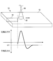
Classifications
-
- C—CHEMISTRY; METALLURGY
- C03—GLASS; MINERAL OR SLAG WOOL
- C03B—MANUFACTURE, SHAPING, OR SUPPLEMENTARY PROCESSES
- C03B33/00—Severing cooled glass
- C03B33/09—Severing cooled glass by thermal shock
-
- C—CHEMISTRY; METALLURGY
- C03—GLASS; MINERAL OR SLAG WOOL
- C03B—MANUFACTURE, SHAPING, OR SUPPLEMENTARY PROCESSES
- C03B33/00—Severing cooled glass
- C03B33/09—Severing cooled glass by thermal shock
- C03B33/091—Severing cooled glass by thermal shock using at least one focussed radiation beam, e.g. laser beam
-
- B—PERFORMING OPERATIONS; TRANSPORTING
- B23—MACHINE TOOLS; METAL-WORKING NOT OTHERWISE PROVIDED FOR
- B23K—SOLDERING OR UNSOLDERING; WELDING; CLADDING OR PLATING BY SOLDERING OR WELDING; CUTTING BY APPLYING HEAT LOCALLY, e.g. FLAME CUTTING; WORKING BY LASER BEAM
- B23K26/00—Working by laser beam, e.g. welding, cutting or boring
- B23K26/02—Positioning or observing the workpiece, e.g. with respect to the point of impact; Aligning, aiming or focusing the laser beam
- B23K26/06—Shaping the laser beam, e.g. by masks or multi-focusing
- B23K26/073—Shaping the laser spot
- B23K26/0732—Shaping the laser spot into a rectangular shape
-
- B—PERFORMING OPERATIONS; TRANSPORTING
- B23—MACHINE TOOLS; METAL-WORKING NOT OTHERWISE PROVIDED FOR
- B23K—SOLDERING OR UNSOLDERING; WELDING; CLADDING OR PLATING BY SOLDERING OR WELDING; CUTTING BY APPLYING HEAT LOCALLY, e.g. FLAME CUTTING; WORKING BY LASER BEAM
- B23K26/00—Working by laser beam, e.g. welding, cutting or boring
- B23K26/02—Positioning or observing the workpiece, e.g. with respect to the point of impact; Aligning, aiming or focusing the laser beam
- B23K26/06—Shaping the laser beam, e.g. by masks or multi-focusing
- B23K26/073—Shaping the laser spot
- B23K26/0736—Shaping the laser spot into an oval shape, e.g. elliptic shape
-
- B—PERFORMING OPERATIONS; TRANSPORTING
- B23—MACHINE TOOLS; METAL-WORKING NOT OTHERWISE PROVIDED FOR
- B23K—SOLDERING OR UNSOLDERING; WELDING; CLADDING OR PLATING BY SOLDERING OR WELDING; CUTTING BY APPLYING HEAT LOCALLY, e.g. FLAME CUTTING; WORKING BY LASER BEAM
- B23K26/00—Working by laser beam, e.g. welding, cutting or boring
- B23K26/14—Working by laser beam, e.g. welding, cutting or boring using a fluid stream, e.g. a jet of gas, in conjunction with the laser beam; Nozzles therefor
-
- B—PERFORMING OPERATIONS; TRANSPORTING
- B23—MACHINE TOOLS; METAL-WORKING NOT OTHERWISE PROVIDED FOR
- B23K—SOLDERING OR UNSOLDERING; WELDING; CLADDING OR PLATING BY SOLDERING OR WELDING; CUTTING BY APPLYING HEAT LOCALLY, e.g. FLAME CUTTING; WORKING BY LASER BEAM
- B23K26/00—Working by laser beam, e.g. welding, cutting or boring
- B23K26/36—Removing material
- B23K26/38—Removing material by boring or cutting
-
- B—PERFORMING OPERATIONS; TRANSPORTING
- B23—MACHINE TOOLS; METAL-WORKING NOT OTHERWISE PROVIDED FOR
- B23K—SOLDERING OR UNSOLDERING; WELDING; CLADDING OR PLATING BY SOLDERING OR WELDING; CUTTING BY APPLYING HEAT LOCALLY, e.g. FLAME CUTTING; WORKING BY LASER BEAM
- B23K26/00—Working by laser beam, e.g. welding, cutting or boring
- B23K26/36—Removing material
- B23K26/40—Removing material taking account of the properties of the material involved
-
- B—PERFORMING OPERATIONS; TRANSPORTING
- B23—MACHINE TOOLS; METAL-WORKING NOT OTHERWISE PROVIDED FOR
- B23K—SOLDERING OR UNSOLDERING; WELDING; CLADDING OR PLATING BY SOLDERING OR WELDING; CUTTING BY APPLYING HEAT LOCALLY, e.g. FLAME CUTTING; WORKING BY LASER BEAM
- B23K26/00—Working by laser beam, e.g. welding, cutting or boring
- B23K26/50—Working by transmitting the laser beam through or within the workpiece
- B23K26/53—Working by transmitting the laser beam through or within the workpiece for modifying or reforming the material inside the workpiece, e.g. for producing break initiation cracks
-
- C—CHEMISTRY; METALLURGY
- C03—GLASS; MINERAL OR SLAG WOOL
- C03B—MANUFACTURE, SHAPING, OR SUPPLEMENTARY PROCESSES
- C03B33/00—Severing cooled glass
- C03B33/07—Cutting armoured, multi-layered, coated or laminated, glass products
-
- B—PERFORMING OPERATIONS; TRANSPORTING
- B23—MACHINE TOOLS; METAL-WORKING NOT OTHERWISE PROVIDED FOR
- B23K—SOLDERING OR UNSOLDERING; WELDING; CLADDING OR PLATING BY SOLDERING OR WELDING; CUTTING BY APPLYING HEAT LOCALLY, e.g. FLAME CUTTING; WORKING BY LASER BEAM
- B23K2101/00—Articles made by soldering, welding or cutting
- B23K2101/006—Vehicles
-
- B—PERFORMING OPERATIONS; TRANSPORTING
- B23—MACHINE TOOLS; METAL-WORKING NOT OTHERWISE PROVIDED FOR
- B23K—SOLDERING OR UNSOLDERING; WELDING; CLADDING OR PLATING BY SOLDERING OR WELDING; CUTTING BY APPLYING HEAT LOCALLY, e.g. FLAME CUTTING; WORKING BY LASER BEAM
- B23K2103/00—Materials to be soldered, welded or cut
- B23K2103/16—Composite materials
- B23K2103/166—Multilayered materials
- B23K2103/172—Multilayered materials wherein at least one of the layers is non-metallic
Definitions
- the laser beam 20 is incident on the surface 12 of the tempered glass plate 10 perpendicularly.
- the laser beam 20 is incident on the surface 12 of the tempered glass plate 10 at an angle. It is different in the point to do. Since other configurations are the same as those of the second embodiment, the description will focus on the differences.
- the refraction angle ⁇ increases in accordance with Snell's law, so that the inclination of the cut surface of the tempered glass plate 10 with respect to the plate thickness direction increases. As this inclination increases, separation in the plate thickness direction after cutting becomes easier, but chamfering of the cut surface after cutting becomes troublesome.
- FIG. 12 is an explanatory diagram of a method for cutting a strengthened glass sheet according to the fifth embodiment of the present invention.
- the same or corresponding components as those in FIG. 1A are denoted by the same or corresponding reference numerals, and description thereof is omitted.
- the tempered glass plates adjacent to each other may be in contact with each other or may be separated from each other.
- spacers such as resin, may be provided between the tempered glass plates adjacent to each other (for example, the tempered glass plate 10A and the tempered glass plate 10B).
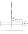
- the laser beam 20 is incident perpendicular to the surface 12A ⁇ 12C of each reinforcing glass plates 10A ⁇ 10C, emitted from the rear surface to move the same distance as the thickness t i (cm) of each reinforcing glass plates 10A ⁇ 10C To do.
- each of the tempered glass plates 10A to 10C and the laser beam 20 satisfies the formula of 0 ⁇ i ⁇ t i ⁇ 3.0, so that the laser beam 20 is converted into the surfaces 12A to 12C of the tempered glass plates 10A to 10C. It reaches the inside without being absorbed in the vicinity.
- the present embodiment can provide the same effects as those of the first embodiment.
- the gas 40 is sprayed onto the surface 112 of the stacked body 110, and the spray region 42 of the gas 40 is applied to the surface 112 of the stacked body 110. It may be moved in conjunction with the irradiation region 22.
- the spray region 42 of the gas 40 may overlap with the irradiation region 22 of the laser light 20 or may be disposed in the vicinity of the irradiation region 22 of the laser light 20. Further, the irradiation region 22 of the laser beam 20 may be disposed inside the outer edge of the spray region 42 of the gas 40.
- Each glass sheet for chemical strengthening is expressed in terms of mass% based on oxide, SiO 2 : 60.7%, Al 2 O 3 : 9.6%, MgO: 7.0%, CaO: 0.1%, SrO. : 0.1%, BaO: 0.1%, Na 2 O: 11.6%, K 2 O: 6.0%, ZrO 2 : 4.8%, iron oxide (Fe 2 O 3 ) was contained in a predetermined amount by external division.
- CT The internal residual tensile stress (CT) of each chemically strengthened glass plate is measured by measuring the surface compressive stress (CS) and the depth (DOL) of the compressive stress layer with a surface stress meter FSM-6000 (manufactured by Orihara Seisakusho). It calculated
- CT (CS ⁇ DOL) / (t ⁇ 2 ⁇ DOL) (I)
- the light source of the laser beam was a fiber laser (central wavelength band: 1075 to 1095 nm).
- the absorption coefficient of each chemically strengthened glass plate with respect to this laser beam was measured using an ultraviolet-visible near-infrared spectrophotometer Lambda950.
- the irradiation region of the laser beam was moved at a constant speed of 10 mm / sec over 50 mm from one end (initial crack) to the other end of the planned cutting line on the surface of each chemically strengthened glass plate.
- the planned cutting line which is the center line of the movement path, was a straight line parallel to one side of the rectangular chemically strengthened glass plate, and the distance from one side was 10 mm.
- the shape of the laser light irradiation area was circular.
- the condensing position of the laser light was arranged at a position of ⁇ 10.3 to 20 mm from the surface (upper surface) of each chemically strengthened glass plate (the upper side (light source side) is positive with respect to the upper surface).
- the converging angle of the laser beam was 1.4 to 33.4 °.
- the maximum deviation amount represents how much the cutting line has deviated from the planned cutting line on the surface of the chemically strengthened glass plate, and is a measurement of the fluctuation range in the direction orthogonal to the planned cutting line. This maximum deviation amount is measured excluding the cutting start portion and the cutting end portion.
- Example 1-5 to Example 1-10 In Example 1-5 to Example 1-10 (Comparative Example), unlike Example 1-1 to Example 1-4 (Example), the value of thickness (t) ⁇ absorption coefficient ( ⁇ ) was set to more than 3.0. An attempt was made to cut a chemically strengthened glass plate.
- the chemically strengthened glass sheet can be cut with good cutting accuracy by setting the value of thickness (t) ⁇ absorption coefficient ( ⁇ ) to 3.0 or less.
- the value of thickness (t) ⁇ absorption coefficient ( ⁇ ) exceeded 3.0, cutting was impossible, or even if it could be cut, the maximum deviation amount was large, and cutting accuracy was poor.
- Example 2-1 to Example 2-20 [Example 2-1 to Example 2-20]
- the chemical strengthening treatment conditions were changed to adjust the internal residual tensile stress (CT), and the relationship between the internal residual tensile stress (CT) and the maximum deviation amount was determined.
- CT internal residual tensile stress
- the production, cutting, and evaluation of the chemically strengthened glass plate were the same as in Examples 1-1 to 1-4.
- the evaluation results are shown in Tables 3 to 5 together with cutting conditions and the like.
- Example 3-1 to Example 3-8 the cutting results were evaluated by changing the size and shape of the laser light irradiation region on the surface of the chemically strengthened glass plate.
- the production, cutting, and evaluation of the chemically strengthened glass plate were the same as in Examples 1-1 to 1-4.
- the diameter ( ⁇ ) is larger than 0.18 mm, and the thickness of the chemically strengthened glass plate (1.0 mm). Smaller than), it can be seen that the cutting edge quality and the cutting surface quality are good.
- the diameter ( ⁇ ) was 0.18 mm, there was a fine crack on the cut surface.
- the diameter ( ⁇ ) was 1.03 mm, the end of the cut surface was slightly curved.
- Example 4-1 to Example 4-4 the chemically tempered glass plate can be cut along the planned cutting line (no self-propelled cracks or glass crushing occurs), and the laser on the surface of the chemically tempered glass plate. The relationship with the diameter of light was investigated.
- Each chemically strengthened glass plate is expressed in terms of mass% on the basis of oxide, SiO 2 : 61.0%, Al 2 O 3 : 12.8%, MgO: 6.6%, CaO: 0.1%, SrO. : 0.2%, BaO: 0.2%, Na 2 O: 12.2%, K 2 O: 5.9%, ZrO 2 : containing 1.0% was used.
- the surface compressive stress (CS) was 735 MPa
- the depth (DOL) of the compressive stress layer was 51.2 ( ⁇ m)
- the internal tensile stress (CT) was 38 (MPa).
- Each chemically strengthened glass plate (300 mm ⁇ 300 mm ⁇ 1.1 mm) was cut by the cutting method shown in FIGS. 10A and 10B.
- An initial crack was previously formed with a file at the cutting start position on the side surface of each chemically strengthened glass plate, and no scribe line was formed on the surface of each chemically strengthened glass plate.
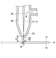
- the exit of the nozzle was a circle with a diameter of 2 mm, and the gap G (see FIG. 10A) between each chemically strengthened glass plate was placed at a position of 3 mm. Compressed air at room temperature was injected from the outlet of the nozzle toward the surface of each chemically strengthened glass plate at a flow rate of 100 L / min.
- the central axis of the nozzle and the optical axis of the laser beam were arranged coaxially so as to be orthogonal to the surface of each chemically strengthened glass plate.
- a fiber laser (center wavelength: 1070 nm) was used as a laser light source.
- the absorption coefficient of each chemically strengthened glass plate with respect to laser light was measured using an ultraviolet-visible near-infrared spectrophotometer Lambda950.
- the condensing position of the laser light was arranged 0 to 2.8 mm above the surface of each chemically strengthened glass plate (on the side opposite to the back surface).
- the condensing angle of the laser beam was 4 °.
- the center of the laser beam was moved over 300 mm from one end of the planned cutting line to the other end.
- the planned cutting line as the movement path was a straight line parallel to one side (short side) of each rectangular chemically strengthened glass plate, and the distance from one side was 10 mm.
- the diameter of the laser beam is set to 0.2 mm and the center of the laser beam is moved from the cutting start edge by 15 mm at a speed of 2.5 mm / sec.
- the diameter of the laser beam was set to the diameter shown in Table 7 while moving 5 mm. Thereafter, the moving speed of the laser beam was accelerated to the target speed and maintained at the target speed. Table 7 shows the maximum speed at which cutting was possible.
- Table 7 shows that when the light source output is constant, the scanning speed of the laser beam can be improved as the diameter of the laser beam is reduced on the surface of the chemically strengthened glass plate. This is because when the light source output of the laser beam is constant, the power density (W / mm 2 ) of the laser beam increases as the diameter of the laser beam decreases on the surface of the chemically strengthened glass plate, so that the heating time can be shortened. .
- Example 5-1 to Example 5-2 the relationship between the minimum light source output that can cut the chemically tempered glass plate along the planned cutting line (no self-running of cracks or glass crushing) and the use of nozzles Examined.
- Each chemically strengthened glass plate (150 mm ⁇ 100 mm ⁇ 1.1 mm) was cut by the cutting method shown in FIGS. 10A and 10B.
- An initial crack was previously formed with a file at the cutting start position on the side surface of each chemically strengthened glass plate, and no scribe line was formed on the surface of each chemically strengthened glass plate.
- a fiber laser (center wavelength: 1070 nm) was used as a laser light source.
- the absorption coefficient of each chemically strengthened glass plate with respect to laser light was measured using an ultraviolet-visible near-infrared spectrophotometer Lambda950.
- the condensing position of the laser beam was arranged at a position 0 mm above (on the opposite side to the back side) from the surface of each chemically strengthened glass plate.
- the condensing angle of the laser light was 8.9 °.
- the center of the laser beam was moved over 150 mm from one end of the planned cutting line to the other end.
- the planned cutting line as the movement path was a straight line parallel to one side (short side) of each rectangular chemically strengthened glass plate, and the distance from one side was 10 mm.
- the diameter of the laser beam is set to 0.2 mm, and the center of the laser beam is moved 15 mm from the cutting start end of the planned cutting line at a speed of 2.5 mm / sec. While the center of the laser beam was further moved by 5 mm, the diameter of the laser beam was reduced from 0.2 mm to 0.1 mm. Thereafter, the moving speed of the laser beam was accelerated to a target speed (10 mm / sec) and maintained at the target speed. The reason why the moving speed is low at the start of cutting is that it takes time to form a crack.
- Example 5-1 a nozzle was not used, and in Example 5-2, a cooling gas was sprayed onto the surface of the chemically strengthened glass plate using a nozzle.
- the central axis of the nozzle was arranged coaxially with the optical axis of the laser beam so as to be orthogonal to the surface of each chemically strengthened glass plate.
- the exit of the nozzle was a circle having a diameter of 1 mm, and the gap G (see FIG. 10A) between each chemically strengthened glass plate was placed at a position of 2 mm. Compressed air at room temperature was injected from the outlet of the nozzle toward the surface of each chemically strengthened glass plate at a flow rate of 15 L / min. Table 9 shows the minimum light source output that could be cut.
- Example 6-1 to Example 6-5 the relationship between the minimum light source output that can cut the chemically strengthened glass plate along the planned cutting line (there is no self-running cracks or glass crushing) and the focusing position of the laser beam Investigated about.
- Each chemically strengthened glass plate (150 mm ⁇ 100 mm ⁇ 1.1 mm) was cut by the cutting method shown in FIGS. 10A and 10B.
- An initial crack was previously formed with a file at the cutting start position on the side surface of each chemically strengthened glass plate, and no scribe line was formed on the surface of each chemically strengthened glass plate.
- a fiber laser (center wavelength: 1070 nm) was used as a laser light source.
- the absorption coefficient of each chemically strengthened glass plate with respect to laser light was measured using an ultraviolet-visible near-infrared spectrophotometer Lambda950.
- the center of the laser beam was moved over 150 mm from one end of the planned cutting line to the other end.
- the planned cutting line as the movement path was a straight line parallel to one side (short side) of each rectangular chemically strengthened glass plate, and the distance from one side was 10 mm.
- the diameter of the laser beam is set to 0.2 mm, and the center of the laser beam is moved 15 mm from the cutting start end of the planned cutting line at a speed of 2.5 mm / sec. While the center of the laser beam was further moved by 5 mm, the diameter of the laser beam was reduced from 0.2 mm to 0.1 mm. Thereafter, the moving speed of the laser beam was accelerated to a target speed (10 mm / sec) and maintained at the target speed. The reason why the moving speed is low at the start of cutting is that it takes time to form a crack.
- the condensing position of the laser beam was set to a position 1.3 mm above the surface of the chemically strengthened glass plate (on the opposite side from the back surface) while the moving speed of the laser beam was low.
- the laser beam condensing position was changed before the laser beam moving speed was switched from low to high.
- the laser beam condensing position after the change is the position 0.4 mm above the surface of the chemically strengthened glass plate in Example 6-1, the position on the surface of the chemically strengthened glass plate in Example 6-2, and the position in Example 6-3.
- the center position in the thickness direction of the chemically strengthened glass plate was set at a position on the back surface of the chemically strengthened glass plate in Example 6-4, and at a position 0.4 mm below the back surface of the chemically strengthened glass plate in Example 6-5.
- the central axis of the nozzle was arranged coaxially with the optical axis of the laser beam so as to be orthogonal to the surface of each chemically strengthened glass plate.
- the exit of the nozzle was a circle with a diameter of 1 mm, and the gap G (see FIG. 10A) between each chemically strengthened glass plate was placed at a position of 2 mm. Compressed air at room temperature was injected from the outlet of the nozzle toward the surface of each chemically strengthened glass plate at a flow rate of 15 L / min. Table 9 shows the minimum light source output that could be cut.
- the condensing position of the laser light is preferably between the front surface and the back surface of the chemically strengthened glass plate, and is closer to the back surface.
- Example 7-1 to Example 7-2 In Examples 7-1 and 7-2, it was examined whether or not chemically strengthened glass sheets having different glass compositions could be cut.
- Example 7-1 a chemically strengthened glass plate having the same composition as in Example 4-1 was cut.
- Example 7-2 in terms of mass% based on oxide, SiO 2 : 62.0%, Al 2 O 3 : 17.1%, MgO: 3.9%, CaO: 0.6%, Na
- Each chemically strengthened glass plate 120 mm ⁇ 100 mm ⁇ 0.8 mm was cut by the cutting method shown in FIGS. 10A and 10B.
- An initial crack was previously formed with a file at the cutting start position on the side surface of each chemically strengthened glass plate, and no scribe line was formed on the surface of each chemically strengthened glass plate.
- a fiber laser (center wavelength: 1070 nm) was used as a laser light source.
- the absorption coefficient of each chemically strengthened glass plate with respect to laser light was measured using an ultraviolet-visible near-infrared spectrophotometer Lambda950.
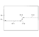
- the planned cutting line 11 which is the movement path includes two straight portions (length 55 mm) 11-1 and 11-4 and the two straight portions 11-1 and 11-4. It includes two curvilinear portions (1/4 arc-shaped portions having a radius of 5 mm) 11-2 and 11-3 arranged between them.
- the diameter of the laser beam is set to 0.2 mm, and the center of the laser beam is moved 15 mm from the cutting start end of the planned cutting line at a speed of 2.5 mm / sec. While the center of the laser beam was further moved by 5 mm, the diameter of the laser beam was reduced from 0.2 mm to 0.1 mm. Thereafter, the moving speed of the laser beam was accelerated to a target speed (10 mm / sec) and maintained at the target speed. The reason why the moving speed is low at the start of cutting is that it takes time to form a crack.
- the condensing position of the laser beam was arranged at a position 0 mm above (on the opposite side to the back side) from the surface of each chemically strengthened glass plate.
- the condensing angle of the laser light was 8.9 °.
- the central axis of the nozzle was arranged coaxially with the optical axis of the laser beam so as to be orthogonal to the surface of each chemically strengthened glass plate.
- the exit of the nozzle was a circle with a diameter of 2 mm, and the gap G (see FIG. 10A) between each chemically strengthened glass plate was placed at a position of 3 mm. Compressed air at room temperature was injected from the outlet of the nozzle toward the surface of each chemically strengthened glass plate at a flow rate of 50 L / min.
- Table 10 shows the cutting evaluation results together with cutting conditions.
- Table 10 shows that the glass composition of a chemically strengthened glass plate is not specifically limited.
- Example 8-1 to Example 8-2 the laser beam was incident obliquely on the surface of the chemically strengthened glass plate (see FIGS. 11A and 11B). The irradiation area of the laser beam was moved on the surface of the plate.
- Example 9 In Example 9, it was examined whether or not a laminated body in which three chemically strengthened glass plates were stacked was cut.
- a fiber laser (central wavelength band: 1075 to 1095 nm, light source output: 80 W) was used as the laser light source.
- the absorption coefficient of each chemically strengthened glass plate with respect to laser light was measured using an ultraviolet-visible near-infrared spectrophotometer Lambda950.
- the laser beam was focused at a position 9 mm above the top surface of the laminate.
- the condensing angle of the laser beam was 1.6 °.
- the diameters of the laser beams in the same plane as the upper surface of each chemically strengthened glass plate were 0.24 mm, 0.27 mm, and 0.30 mm from the upper side, respectively.
- the center of the laser beam was moved at a constant speed of 2.5 mm / sec over 150 mm from one end of the planned cutting line to the other end.
- the planned cutting line as the movement path was a straight line parallel to one side (short side) of the rectangular chemically strengthened glass plate, and the distance from one side was 10 mm.
- Example 10-1 to Example 10-2 In Examples 10-1 to 10-2, it was investigated whether or not the air-cooled tempered glass sheet could be cut.
- Each air-cooled tempered glass plate is prepared by melting glass raw materials prepared by mixing multiple types of raw materials, forming the molten glass into a plate shape, cooling it to near room temperature, cutting, cutting, and double-sided mirror polishing Produced. In the course of cooling, the glass at a temperature near the softening point was quenched from the front and back surfaces to form a front layer and a back layer where compressive stress remained. The rapid cooling conditions were set so that the internal residual tensile stress (CT) was a desired value.
- CT internal residual tensile stress
- Each air-cooled tempered glass plate is expressed in terms of mass% on the basis of oxide, SiO 2 : 72.4%, Al 2 O 3 : 1.9%, MgO: 3.8%, CaO: 8.3%, Na 2 O: 12.7%, K 2 O: 1.0%.
- CM CS / a
- a a constant determined by the temperature at the start of rapid cooling of the glass, the rapid cooling rate of the glass, the thickness of the glass, etc., and is usually in the range of 2.2 to 2.5. In Example 10-1 to Example 10-2, 2.35 was used as the value of a.
- Each air-cooled tempered glass plate (300 mm ⁇ 300 mm ⁇ 5 mm) was cut by the cutting method shown in FIGS. 1A and 1B. Since the side surface of each air-cooled tempered glass plate is a surface ground in advance by a rotating grindstone before cutting, no initial crack was formed at the cutting start position on the side surface of each air-cooled tempered glass plate before cutting. Further, no scribe line was formed on the surface of each air-cooled tempered glass plate.
- a fiber laser (center wavelength: 1070 nm) was used as a laser light source.
- the absorption coefficient of each air-cooled tempered glass plate with respect to laser light was measured using an ultraviolet-visible near-infrared spectrophotometer Lambda 950.
- the optical axis of the laser beam was arranged so as to be orthogonal to the surface of each air-cooled tempered glass plate.
- the laser beam was focused at a position 25.6 mm above the surface of each air-cooled tempered glass plate (on the opposite side from the back surface).
- the condensing angle of the laser light was 8.9 °.
- the irradiation area of the laser beam was a circle with a diameter of 4 mm and moved at a constant speed of 2.5 mm / sec.
- the light source output of the laser beam is set to 200 W in Example 10-1 and 240 W in Example 10-2. After that, it was set to 100W.
- the film 18 when the film 18 is formed on the surface 12 of the tempered glass plate 10, the film 18 is removed along the planned cutting line by a pulse laser and then cut. good.
- the means for removing the film 18 is not limited to using a laser beam such as a pulse laser, and any means that can remove the film, such as a mechanical means, may be used.
Landscapes
- Physics & Mathematics (AREA)
- Optics & Photonics (AREA)
- Engineering & Computer Science (AREA)
- Chemical & Material Sciences (AREA)
- Mechanical Engineering (AREA)
- Plasma & Fusion (AREA)
- Organic Chemistry (AREA)
- Materials Engineering (AREA)
- Thermal Sciences (AREA)
- Toxicology (AREA)
- Health & Medical Sciences (AREA)
- Chemical Kinetics & Catalysis (AREA)
- General Chemical & Material Sciences (AREA)
- Oil, Petroleum & Natural Gas (AREA)
- Re-Forming, After-Treatment, Cutting And Transporting Of Glass Products (AREA)
- Laser Beam Processing (AREA)
- Processing Of Stones Or Stones Resemblance Materials (AREA)
- Surface Treatment Of Glass (AREA)
Abstract
Description
残留圧縮応力を有する表面層及び裏面層と、表面層と裏面層との間に形成され、内部残留引張応力を有する中間層とを備える強化ガラス板を、該強化ガラス板の表面にレーザ光を照射し、該表面上で切断予定線に沿って前記レーザ光の照射領域を移動させ、前記照射領域の後方に前記強化ガラス板を板厚方向に貫通するクラックを追従させて前記強化ガラス板を切断する強化ガラス板の切断方法において、
前記レーザ光の前記照射領域における前記中間層を徐冷点以下の温度で加熱し、前記照射領域の中心における前記中間層に前記内部残留引張応力の値よりも小さい引張応力、または、圧縮応力を形成させ、前記クラックの伸展を抑制させることを特徴とする。
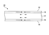
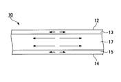
図1A及び図1Bは、本発明の第1の実施形態に係る強化ガラス板の切断方法の説明図である。図1Bは、図1Aの平面図である。図1A及び図1Bに示すように、強化ガラス板10の表面(一方の主面)12にレーザ光20を照射し、強化ガラス板10の表面12上で、レーザ光20の照射領域22を移動させることで、強化ガラス板10に応力を印加して、強化ガラス板10を切断する。
図9は、本発明の第2の実施形態に係る強化ガラス板の切断方法の説明図である。図9において、図1Aと同一構成には同一符号を付して説明を省略する。
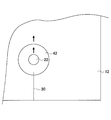
図10A及び図10Bは、本発明の第3の実施形態に係る強化ガラス板の切断方法の説明図である。図10Aは強化ガラス板の断面を示す断面図、図10Bは強化ガラス板の表面を拡大して示す平面図である。図10Aにおいて、矢印方向はガスの流れ方向を示す。図10A及び図10Bにおいて、図1A及び図9等と同一構成には同一符号を付して説明を省略する。
図11A及び図11Bは、本発明の第4の実施形態に係る強化ガラス板の切断方法の説明図である。図11Aは、図11BのA-A線に沿った断面図である。図11Bは、強化ガラス板の平面図である。図11A及び図11Bにおいて、図1A等と同一構成には同一符号を付して説明を省略する。
図12は、本発明の第5の実施形態に係る強化ガラス板の切断方法の説明図である。図12において、図1Aと同一のまたは対応する構成には同一のまたは対応する符号を付して説明を省略する。
(化学強化ガラス板の作製)
化学強化用のガラス板として、複数種類の原料を混ぜて調製したガラス原料を溶解し、溶解した溶融ガラスを板状に成形し室温付近まで徐冷し、切断、切削、両面鏡面研磨することにより、所定の厚さを有する50mm×50mmのガラス板を作製した。ガラス原料は、ガラス板のレーザ光に対する吸収係数(α)が所望の値となるように、同じ配合比のベース材に対する酸化鉄(Fe2O3)の粉末の添加量を変えて調製した。
CT=(CS×DOL)/(t-2×DOL) (I)
なお、測定の結果、各化学強化ガラス板の表面層及び裏面層は、同じ厚さ、同じ最大圧縮応力を有していた。
CT=(C1×D1/2+C2×D2/2)/(t-D1-D2) (II)
上記式(II)中、C1は表面層の最大残留圧縮応力、D1は表面層の厚さ、C2は裏面層の最大残留圧縮応力、D2は裏面層の厚さを示す。
化学強化ガラス板の切断は、図1A及び図1Bに示す切断方法で行った。各化学強化ガラス板の側面の切断開始位置にはヤスリで初期クラックを予め形成し、各化学強化ガラス板の表面にはスクライブ線を形成しなかった。
切断結果は、(1)切断可否、(2)切断端部品質、(3)切断面品質、(4)最大ずれ量で評価した。

表1に示す例1-1~例1-4では、切断可否、切断端部品質、切断面品質のいずれの評価も「○」であり、最大ずれ量は0mmであった。
例1-5~例1-10(比較例)では、例1-1~例1-4(実施例)と異なり、厚さ(t)×吸収係数(α)の値を3.0超とし、化学強化ガラス板の切断を試みた。

例2-1~例2-20(実施例)では、化学強化処理条件を変更して、内部残留引張応力(CT)を調節し、内部残留引張応力(CT)と最大ずれ量との関係を調べた。化学強化ガラス板の作製、切断、評価は、例1-1~例1-4と同様とした。評価結果を、切断条件などと共に、表3~表5に示す。

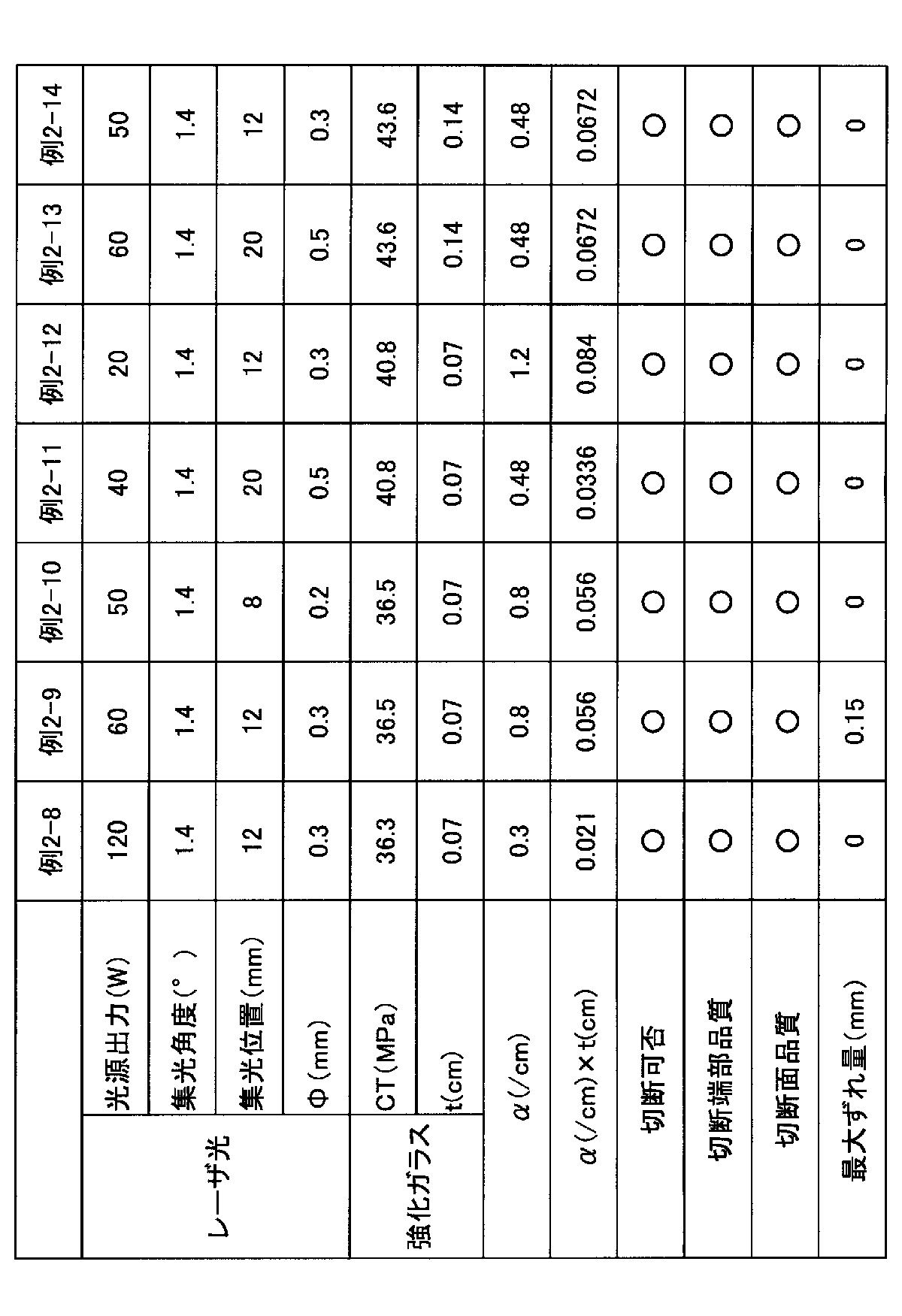

例3-1~例3-8(実施例)では、化学強化ガラス板の表面におけるレーザ光の照射領域の寸法形状を変更して、切断結果を評価した。化学強化ガラス板の作製、切断、評価は、例1-1~例1-4と同様とした。

例4-1~例4-4では、化学強化ガラス板を切断予定線で切断できる(クラックの自走やガラスの粉砕が起きない)最大のレーザ走査速度と、化学強化ガラス板の表面におけるレーザ光の直径との関係について調べた。

例5-1~例5-2では、化学強化ガラス板を切断予定線で切断できる(クラックの自走やガラスの粉砕が起きない)最小の光源出力と、ノズルの使用の有無との関係について調べた。

例6-1~例6-5では、化学強化ガラス板を切断予定線で切断できる(クラックの自走やガラスの粉砕が起きない)最小の光源出力と、レーザ光の集光位置との関係について調べた。

表9から、光源出力を低減するためには、レーザ光の集光位置は、化学強化ガラス板の表面と裏面との間にあることが好ましく、裏面に近いほど好ましいことがわかる。
例7-1~例7-2では、異なるガラス組成の化学強化ガラス板の切断の可否を調べた。
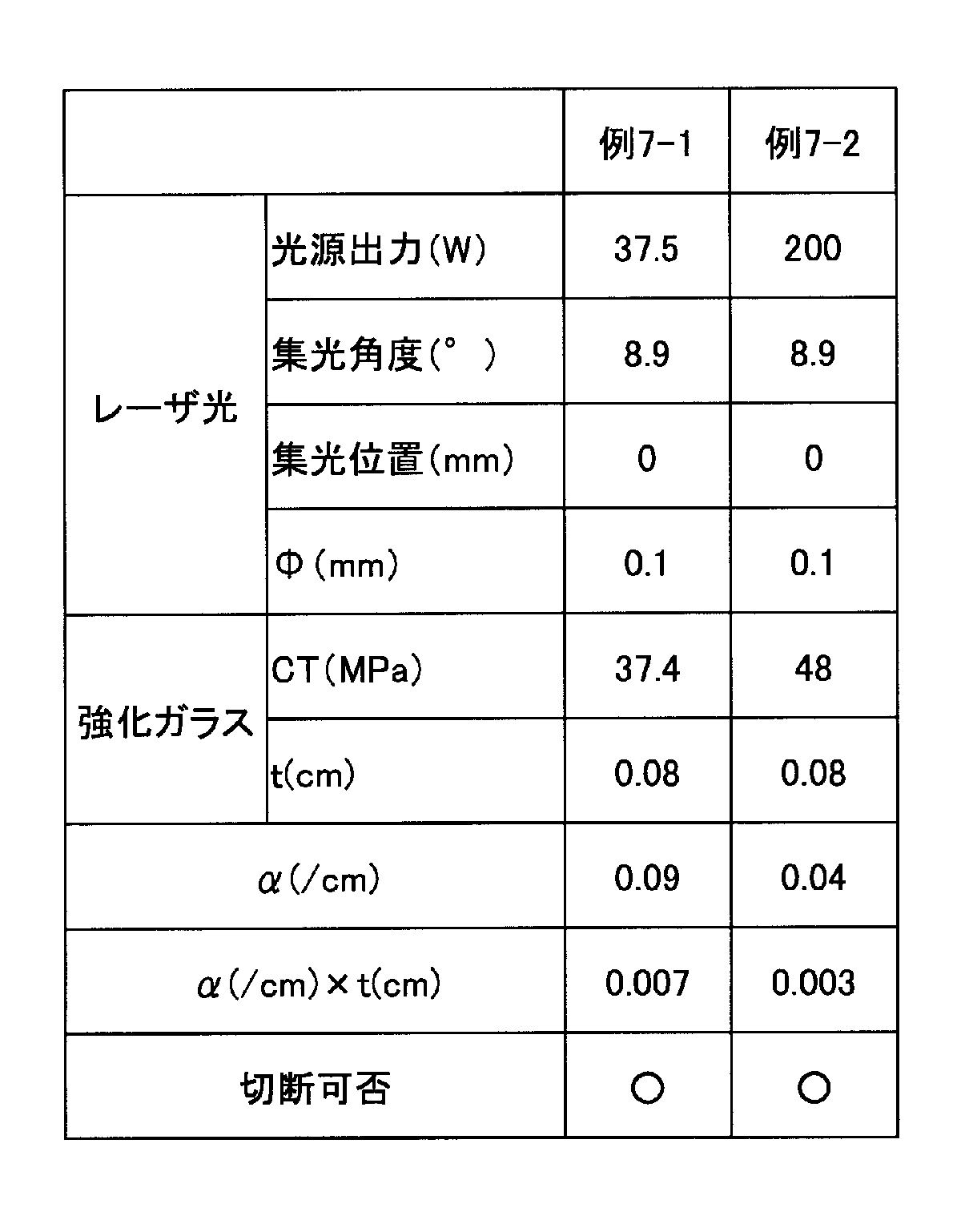
例8-1~例8-2では、化学強化ガラス板の表面に対してレーザ光を斜めに入射した(図11A及び図11B参照)他は、例5-2と同様にして、化学強化ガラス板の表面上で、レーザ光の照射領域を移動させた。

例9では、化学強化ガラス板を3枚重ねた積層体の切断の可否を調べた。
例10-1~例10-2では、風冷強化ガラス板の切断の可否を調べた。
CM=CS/a (III)
数式(III)において、aはガラスの急冷開始時の温度、ガラスの急冷速度、ガラスの厚さなどで決まる定数であって、通常は2.2~2.5の範囲内である。例10-1~例10-2では、aの値として2.35を用いた。

11 切断予定線
12 表面
13 表面層
14 裏面
15 裏面層
17 中間層
20 レーザ光
21 レーザ光の光軸
22 レーザ光の照射領域
30 クラック
40 ガス
42 ガスの吹き付け領域
50 ノズル
51 ノズルの中心軸
52 ノズルの出口
110 積層体
112 積層体の表面
Claims (15)
- 残留圧縮応力を有する表面層及び裏面層と、表面層と裏面層との間に形成され、内部残留引張応力を有する中間層とを備える強化ガラス板を、該強化ガラス板の表面にレーザ光を照射し、該表面上で切断予定線に沿って前記レーザ光の照射領域を移動させ、前記照射領域の後方に前記強化ガラス板を板厚方向に貫通するクラックを追従させて前記強化ガラス板を切断する強化ガラス板の切断方法において、
前記レーザ光の前記照射領域における前記中間層を徐冷点以下の温度で加熱し、前記照射領域の中心における前記中間層に前記内部残留引張応力の値よりも小さい引張応力、または、圧縮応力を形成させ、前記クラックの伸展を抑制させることを特徴とする強化ガラス板の切断方法。 - 前記強化ガラス板と前記レーザ光とは、
前記レーザ光が前記強化ガラス板の前記表面に対して垂直に入射する場合、前記レーザ光に対する前記強化ガラス板の吸収係数をα(cm-1)、前記強化ガラス板の厚さをt(cm)として、0<α×t≦3.0の式を満たし、
前記レーザ光が前記強化ガラス板の前記表面に対して斜めに入射する場合、前記強化ガラス板の前記表面での前記レーザ光の屈折角をγ(°)として、0<α×t/cosγ≦3.0の式を満たす請求項1に記載の強化ガラス板の切断方法。 - 前記レーザ光の波長が250~5000nmである請求項1または2に記載の強化ガラス板の切断方法。
- 前記中間層の内部残留引張応力が15MPa以上である請求項1~3のいずれか1項に記載の強化ガラス板の切断方法。
- 前記中間層の内部残留引張応力が30MPa以上である請求項4に記載の強化ガラス板の切断方法。
- 前記強化ガラス板の前記表面において、前記レーザ光の照射領域は、円状に形成されており、前記強化ガラス板の厚さよりも小さい直径を有する請求項1~5のいずれか1項に記載の強化ガラス板の切断方法。
- 前記強化ガラス板は、化学強化ガラスである請求項1~6のいずれか1項に記載の強化ガラス板の切断方法。
- 前記強化ガラス板の厚さは、0.01cm以上0.2cm以下である請求項7に記載の強化ガラス板の切断方法。
- 前記強化ガラス板は、風冷強化ガラスである請求項1~6のいずれか1項に記載の強化ガラス板の切断方法。
- 前記強化ガラス板の厚さは、0.1cm以上3cm以下である請求項9に記載の強化ガラス板の切断方法。
- 前記レーザ光の光軸は、前記強化ガラス板の表面に対して斜めである請求項1~10のいずれか1項に記載の強化ガラス板の切断方法。
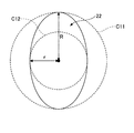
- 前記強化ガラス板の前記表面において、前記レーザ光の照射領域の外接円の半径をRとしたとき、前記照射領域の真円度が0.5R以下である請求項1~11のいずれか1項に記載の強化ガラス板の切断方法。
- 前記レーザ光の集光位置が、前記強化ガラス板の前記中間層に位置する請求項1~12のいずれか1項に記載の強化ガラス板の切断方法。
- 前記強化ガラス板の表面にガスを吹き付け、前記強化ガラス板の表面上で、前記ガスの吹き付け領域を前記レーザ光の照射領域と連動して移動させる請求項1~13のいずれか1項に記載の強化ガラス板の切断方法。
- 前記ガスは、前記強化ガラス板を局所的に冷却する冷却ガスである請求項14に記載の強化ガラス板の切断方法。
Priority Applications (5)
| Application Number | Priority Date | Filing Date | Title |
|---|---|---|---|
| JP2012517031A JP5431583B2 (ja) | 2011-01-11 | 2012-01-11 | 強化ガラス板の切断方法 |
| CN2012800046786A CN103298757A (zh) | 2011-01-11 | 2012-01-11 | 强化玻璃板的切断方法 |
| KR1020137018006A KR20140024843A (ko) | 2011-01-11 | 2012-01-11 | 강화 유리판의 절단 방법 |
| EP12734331.7A EP2664592A4 (en) | 2011-01-11 | 2012-01-11 | CUTTING METHOD FOR REINFORCED GLASS PLATES |
| US13/934,463 US20130291598A1 (en) | 2011-01-11 | 2013-07-03 | Method of cutting strengthened glass plate |
Applications Claiming Priority (4)
| Application Number | Priority Date | Filing Date | Title |
|---|---|---|---|
| JP2011-003496 | 2011-01-11 | ||
| JP2011003496 | 2011-01-11 | ||
| JP2011-190024 | 2011-08-31 | ||
| JP2011190024 | 2011-08-31 |
Related Child Applications (1)
| Application Number | Title | Priority Date | Filing Date |
|---|---|---|---|
| US13/934,463 Continuation US20130291598A1 (en) | 2011-01-11 | 2013-07-03 | Method of cutting strengthened glass plate |
Publications (1)
| Publication Number | Publication Date |
|---|---|
| WO2012096285A1 true WO2012096285A1 (ja) | 2012-07-19 |
Family
ID=46506970
Family Applications (5)
| Application Number | Title | Priority Date | Filing Date |
|---|---|---|---|
| PCT/JP2011/076289 Ceased WO2012096053A1 (ja) | 2011-01-11 | 2011-11-15 | 強化ガラス板の切断方法 |
| PCT/JP2012/050283 Ceased WO2012096261A1 (ja) | 2011-01-11 | 2012-01-10 | レーザ切断用の化学強化ガラス板 |
| PCT/JP2012/050282 Ceased WO2012096260A1 (ja) | 2011-01-11 | 2012-01-10 | レーザ切断前の化学強化に用いられるガラス板 |
| PCT/JP2012/050335 Ceased WO2012096285A1 (ja) | 2011-01-11 | 2012-01-11 | 強化ガラス板の切断方法 |
| PCT/JP2012/050334 Ceased WO2012096284A1 (ja) | 2011-01-11 | 2012-01-11 | 強化ガラス板の切断方法 |
Family Applications Before (3)
| Application Number | Title | Priority Date | Filing Date |
|---|---|---|---|
| PCT/JP2011/076289 Ceased WO2012096053A1 (ja) | 2011-01-11 | 2011-11-15 | 強化ガラス板の切断方法 |
| PCT/JP2012/050283 Ceased WO2012096261A1 (ja) | 2011-01-11 | 2012-01-10 | レーザ切断用の化学強化ガラス板 |
| PCT/JP2012/050282 Ceased WO2012096260A1 (ja) | 2011-01-11 | 2012-01-10 | レーザ切断前の化学強化に用いられるガラス板 |
Family Applications After (1)
| Application Number | Title | Priority Date | Filing Date |
|---|---|---|---|
| PCT/JP2012/050334 Ceased WO2012096284A1 (ja) | 2011-01-11 | 2012-01-11 | 強化ガラス板の切断方法 |
Country Status (7)
| Country | Link |
|---|---|
| US (2) | US20130291598A1 (ja) |
| EP (2) | EP2664591A4 (ja) |
| JP (2) | JP5201295B2 (ja) |
| KR (2) | KR20140024842A (ja) |
| CN (2) | CN103298756A (ja) |
| TW (4) | TW201240931A (ja) |
| WO (5) | WO2012096053A1 (ja) |
Cited By (9)
| Publication number | Priority date | Publication date | Assignee | Title |
|---|---|---|---|---|
| WO2013031771A1 (ja) * | 2011-08-31 | 2013-03-07 | 旭硝子株式会社 | 強化ガラスの切断方法 |
| WO2013031655A1 (ja) * | 2011-08-29 | 2013-03-07 | 旭硝子株式会社 | 強化ガラス板の切断方法、および強化ガラス板切断装置 |
| WO2013031778A1 (ja) * | 2011-08-31 | 2013-03-07 | 旭硝子株式会社 | 強化ガラス板の切断方法、および強化ガラス板切断装置 |
| WO2014010599A1 (ja) * | 2012-07-11 | 2014-01-16 | 旭硝子株式会社 | 積層板の製造方法 |
| WO2014010686A1 (ja) * | 2012-07-11 | 2014-01-16 | 旭硝子株式会社 | 機能性基板の製造方法 |
| WO2014010600A1 (ja) * | 2012-07-11 | 2014-01-16 | 旭硝子株式会社 | 湾曲板の製造方法 |
| WO2014010689A1 (ja) * | 2012-07-11 | 2014-01-16 | 旭硝子株式会社 | 小サイズ板の製造方法及び構造体並びに構造体の製造方法 |
| KR101521542B1 (ko) * | 2013-09-06 | 2015-05-29 | 주식회사 제우스 | 강화유리 절단장치 및 강화유리 절단방법 |
| JP2017507101A (ja) * | 2014-01-09 | 2017-03-16 | コーニング インコーポレイテッド | 薄い可撓性ガラスの自由形状切断のための方法および装置 |
Families Citing this family (77)
| Publication number | Priority date | Publication date | Assignee | Title |
|---|---|---|---|---|
| WO2011025908A1 (en) * | 2009-08-28 | 2011-03-03 | Corning Incorporated | Methods for laser cutting articles from chemically strengthened glass substrates |
| JP5929898B2 (ja) | 2011-03-18 | 2016-06-08 | 旭硝子株式会社 | ディスプレイ装置用化学強化ガラス |
| WO2014033905A1 (ja) * | 2012-08-31 | 2014-03-06 | Minami Hironori | 強化ガラスの加工方法及び強化ガラス用加工装置 |
| KR101355807B1 (ko) * | 2012-09-11 | 2014-02-03 | 로체 시스템즈(주) | 비금속 재료의 곡선 절단방법 |
| US9126857B2 (en) * | 2012-11-15 | 2015-09-08 | Corning Incorporated | Separation apparatuses for separating sheets of brittle material and methods for separating sheets of brittle material |
| WO2014079478A1 (en) * | 2012-11-20 | 2014-05-30 | Light In Light Srl | High speed laser processing of transparent materials |
| EP2754524B1 (de) | 2013-01-15 | 2015-11-25 | Corning Laser Technologies GmbH | Verfahren und Vorrichtung zum laserbasierten Bearbeiten von flächigen Substraten, d.h. Wafer oder Glaselement, unter Verwendung einer Laserstrahlbrennlinie |
| EP2781296B1 (de) | 2013-03-21 | 2020-10-21 | Corning Laser Technologies GmbH | Vorrichtung und verfahren zum ausschneiden von konturen aus flächigen substraten mittels laser |
| CN105189395A (zh) * | 2013-04-12 | 2015-12-23 | 旭硝子株式会社 | 室外用化学强化玻璃板 |
| TWI471279B (zh) * | 2013-04-22 | 2015-02-01 | Taiwan Mitsuboshi Diamond Ind Co Ltd | 用於一化學強化玻璃基板之加工方法及加工設備 |
| JP2016128362A (ja) * | 2013-04-26 | 2016-07-14 | 旭硝子株式会社 | ガラス板の切断方法 |
| US9328011B2 (en) * | 2013-06-04 | 2016-05-03 | Coherent, Inc. | Laser-scribing of chemically strengthened glass |
| KR101682269B1 (ko) * | 2013-09-25 | 2016-12-05 | 주식회사 엘지화학 | 레이저 커팅 장치 및 그 커팅 방법 |
| CN103522031B (zh) * | 2013-09-30 | 2016-06-29 | 苏州德龙激光股份有限公司 | 强化玻璃打孔方法 |
| US9701563B2 (en) | 2013-12-17 | 2017-07-11 | Corning Incorporated | Laser cut composite glass article and method of cutting |
| US11556039B2 (en) | 2013-12-17 | 2023-01-17 | Corning Incorporated | Electrochromic coated glass articles and methods for laser processing the same |
| US20150165560A1 (en) | 2013-12-17 | 2015-06-18 | Corning Incorporated | Laser processing of slots and holes |
| US9676167B2 (en) | 2013-12-17 | 2017-06-13 | Corning Incorporated | Laser processing of sapphire substrate and related applications |
| US9815730B2 (en) | 2013-12-17 | 2017-11-14 | Corning Incorporated | Processing 3D shaped transparent brittle substrate |
| US10442719B2 (en) | 2013-12-17 | 2019-10-15 | Corning Incorporated | Edge chamfering methods |
| US9850160B2 (en) | 2013-12-17 | 2017-12-26 | Corning Incorporated | Laser cutting of display glass compositions |
| US10293436B2 (en) | 2013-12-17 | 2019-05-21 | Corning Incorporated | Method for rapid laser drilling of holes in glass and products made therefrom |
| CN106458693B (zh) * | 2014-02-20 | 2020-06-16 | 康宁股份有限公司 | 用于在柔性薄玻璃中切割多个半径的方法和设备 |
| JP2015156427A (ja) * | 2014-02-20 | 2015-08-27 | アイシン精機株式会社 | ガラス加工部品及びその製造方法並びに電子装置及びその製造方法 |
| DE102014205066A1 (de) * | 2014-03-19 | 2015-10-08 | Schott Ag | Vorgespannter Glasartikel mit Laserinnengravur und Herstellverfahren |
| CN103880277B (zh) * | 2014-03-26 | 2016-08-24 | 扬朋科技股份有限公司 | 强化玻璃的切割方法 |
| KR102445217B1 (ko) | 2014-07-08 | 2022-09-20 | 코닝 인코포레이티드 | 재료를 레이저 가공하는 방법 및 장치 |
| WO2016010991A1 (en) | 2014-07-14 | 2016-01-21 | Corning Incorporated | Interface block; system for and method of cutting a substrate being transparent within a range of wavelengths using such interface block |
| EP3536440A1 (en) | 2014-07-14 | 2019-09-11 | Corning Incorporated | Glass article with a defect pattern |
| WO2016010949A1 (en) | 2014-07-14 | 2016-01-21 | Corning Incorporated | Method and system for forming perforations |
| LT3169477T (lt) * | 2014-07-14 | 2020-05-25 | Corning Incorporated | Skaidrių medžiagų apdorojimo sistema ir būdas, naudojant lazerio pluošto židinio linijas, kurių ilgis ir skersmuo yra reguliuojami |
| US11097974B2 (en) | 2014-07-31 | 2021-08-24 | Corning Incorporated | Thermally strengthened consumer electronic glass and related systems and methods |
| KR102448778B1 (ko) * | 2014-08-20 | 2022-09-29 | 코닝 인코포레이티드 | 얇은 가요성 유리의 절단시 높은 에지 강도를 산출하기 위한 장치 및 방법 |
| WO2016033040A1 (en) | 2014-08-28 | 2016-03-03 | Corning Incorporated | Apparatus and method for cutting a glass sheet |
| JP6303950B2 (ja) * | 2014-09-19 | 2018-04-04 | 旭硝子株式会社 | ガラス板の加工方法 |
| KR102185197B1 (ko) * | 2014-10-17 | 2020-12-01 | 동우 화인켐 주식회사 | 유도 가열 장치 |
| TW201628751A (zh) * | 2014-11-20 | 2016-08-16 | 康寧公司 | 彈性玻璃基板之回饋控制的雷射切割 |
| US10047001B2 (en) | 2014-12-04 | 2018-08-14 | Corning Incorporated | Glass cutting systems and methods using non-diffracting laser beams |
| JP2018507154A (ja) | 2015-01-12 | 2018-03-15 | コーニング インコーポレイテッド | マルチフォトン吸収方法を用いた熱強化基板のレーザー切断 |
| WO2016154284A1 (en) | 2015-03-24 | 2016-09-29 | Corning Incorporated | Laser cutting and processing of display glass compositions |
| CN107666983B (zh) | 2015-03-27 | 2020-10-02 | 康宁股份有限公司 | 可透气窗及其制造方法 |
| CN110372230B (zh) * | 2015-05-15 | 2020-05-19 | Agc株式会社 | 化学增强玻璃 |
| WO2017007868A1 (en) | 2015-07-07 | 2017-01-12 | Corning Incorporated | Apparatuses and methods for heating moving glass ribbons at separation lines and/or for separating glass sheets from glass ribbons |
| KR102499697B1 (ko) | 2015-07-10 | 2023-02-14 | 코닝 인코포레이티드 | 유연한 기판 시트에서의 홀의 연속 제조 방법 및 이에 관한 물품 |
| US12338159B2 (en) | 2015-07-30 | 2025-06-24 | Corning Incorporated | Thermally strengthened consumer electronic glass and related systems and methods |
| WO2017023673A1 (en) * | 2015-07-31 | 2017-02-09 | Corning Incorporated | Strengthened asymmetric glass laminates |
| CN107922259B (zh) * | 2015-09-04 | 2021-05-07 | Agc株式会社 | 玻璃板的制造方法、玻璃板、玻璃物品的制造方法、玻璃物品以及玻璃物品的制造装置 |
| KR101952085B1 (ko) | 2016-01-12 | 2019-05-21 | 코닝 인코포레이티드 | 얇은, 열적 및 화학적으로 강화된 유리-계 제품 |
| US11795102B2 (en) * | 2016-01-26 | 2023-10-24 | Corning Incorporated | Non-contact coated glass and related coating system and method |
| KR102405144B1 (ko) | 2016-05-06 | 2022-06-07 | 코닝 인코포레이티드 | 투명 기판들로부터의 윤곽 형상들의 레이저 절단 및 제거 |
| US10410883B2 (en) | 2016-06-01 | 2019-09-10 | Corning Incorporated | Articles and methods of forming vias in substrates |
| US10794679B2 (en) | 2016-06-29 | 2020-10-06 | Corning Incorporated | Method and system for measuring geometric parameters of through holes |
| JP7090594B2 (ja) | 2016-07-29 | 2022-06-24 | コーニング インコーポレイテッド | レーザ加工するための装置および方法 |
| US10522963B2 (en) | 2016-08-30 | 2019-12-31 | Corning Incorporated | Laser cutting of materials with intensity mapping optical system |
| WO2018064409A1 (en) | 2016-09-30 | 2018-04-05 | Corning Incorporated | Apparatuses and methods for laser processing transparent workpieces using non-axisymmetric beam spots |
| LT3529214T (lt) | 2016-10-24 | 2021-02-25 | Corning Incorporated | Substrato apdorojimo stotis lakšto formos stiklo substratų lazeriniam mašininiam apdorojimui |
| US10752534B2 (en) | 2016-11-01 | 2020-08-25 | Corning Incorporated | Apparatuses and methods for laser processing laminate workpiece stacks |
| US10688599B2 (en) | 2017-02-09 | 2020-06-23 | Corning Incorporated | Apparatus and methods for laser processing transparent workpieces using phase shifted focal lines |
| US11078112B2 (en) | 2017-05-25 | 2021-08-03 | Corning Incorporated | Silica-containing substrates with vias having an axially variable sidewall taper and methods for forming the same |
| US10580725B2 (en) | 2017-05-25 | 2020-03-03 | Corning Incorporated | Articles having vias with geometry attributes and methods for fabricating the same |
| US10626040B2 (en) | 2017-06-15 | 2020-04-21 | Corning Incorporated | Articles capable of individual singulation |
| US20190039940A1 (en) * | 2017-08-02 | 2019-02-07 | Guardian Glass, LLC | Laser cutting strengthened glass |
| CN107529467B (zh) * | 2017-08-21 | 2019-10-25 | 成都莱普科技有限公司 | 一种硅基mems晶圆多焦点激光切割系统及切割方法 |
| JP2020531392A (ja) * | 2017-08-25 | 2020-11-05 | コーニング インコーポレイテッド | アフォーカルビーム調整アセンブリを用いて透明被加工物をレーザ加工するための装置及び方法 |
| DE102017121140A1 (de) * | 2017-09-01 | 2019-03-07 | Fraunhofer-Gesellschaft zur Förderung der angewandten Forschung e.V. | Laserbearbeitung eines transparenten Werkstücks |
| TWI785156B (zh) | 2017-11-30 | 2022-12-01 | 美商康寧公司 | 具有高熱膨脹係數及對於熱回火之優先破裂行為的非離子交換玻璃 |
| US12180108B2 (en) | 2017-12-19 | 2024-12-31 | Corning Incorporated | Methods for etching vias in glass-based articles employing positive charge organic molecules |
| US11554984B2 (en) | 2018-02-22 | 2023-01-17 | Corning Incorporated | Alkali-free borosilicate glasses with low post-HF etch roughness |
| TW201946882A (zh) * | 2018-05-07 | 2019-12-16 | 美商康寧公司 | 透明氧化物玻璃的雷射誘導分離 |
| CO2018008278A1 (es) * | 2018-06-30 | 2018-10-22 | Agp America Sa | Método para la fabricación de acristalamiento enrasado para vehículos |
| WO2020039970A1 (ja) * | 2018-08-20 | 2020-02-27 | 日本ゼオン株式会社 | カットフィルムの製造方法、カットフィルム、及びカットフィルム用フィルム |
| CN113727954A (zh) | 2019-04-23 | 2021-11-30 | 康宁股份有限公司 | 具有确定的应力分布曲线的玻璃层叠物及其制作方法 |
| DE102019119195A1 (de) | 2019-07-16 | 2021-01-21 | Schott Ag | Hermetisch verschlossene gehärtete Glasumhäusung und Verfahren zu deren Herstellung |
| CN114514115B (zh) | 2019-08-06 | 2023-09-01 | 康宁股份有限公司 | 具有用于阻止裂纹的埋入式应力尖峰的玻璃层压体及其制造方法 |
| KR20210110510A (ko) * | 2020-02-28 | 2021-09-08 | 쇼오트 아게 | 유리 부재의 분리 방법 및 유리 서브부재 |
| EP3875436B1 (de) | 2020-03-06 | 2024-01-17 | Schott Ag | Verfahren zum vorbereiten und/oder durchführen des trennens eines substratelements und substratteilelement |
| EP4086030B1 (en) * | 2021-05-07 | 2025-01-22 | Infineon Technologies AG | Method for separating substrates |
Citations (6)
| Publication number | Priority date | Publication date | Assignee | Title |
|---|---|---|---|---|
| JP2003001449A (ja) * | 2000-09-13 | 2003-01-08 | Hamamatsu Photonics Kk | レーザ加工装置 |
| WO2003076151A1 (en) * | 2002-03-12 | 2003-09-18 | Mitsuboshi Diamond Industrial Co., Ltd. | Method and device for processing fragile material |
| JP2006256944A (ja) * | 2005-03-14 | 2006-09-28 | Lemi Ltd | 脆性材料の割断方法及び装置 |
| JP2007301624A (ja) * | 2006-05-15 | 2007-11-22 | Shibaura Mechatronics Corp | 割断装置及び割断方法 |
| JP2008247732A (ja) | 2007-03-02 | 2008-10-16 | Nippon Electric Glass Co Ltd | 強化板ガラスとその製造方法 |
| JP2010089143A (ja) * | 2008-10-10 | 2010-04-22 | Mitsuboshi Diamond Industrial Co Ltd | 脆性材料基板の割断方法及び割断装置 |
Family Cites Families (14)
| Publication number | Priority date | Publication date | Assignee | Title |
|---|---|---|---|---|
| DE19952331C1 (de) * | 1999-10-29 | 2001-08-30 | Schott Spezialglas Gmbh | Verfahren und Vorrichtung zum schnellen Schneiden eines Werkstücks aus sprödbrüchigem Werkstoff mittels Laserstrahlen |
| JP2001139342A (ja) * | 1999-11-09 | 2001-05-22 | Nippon Sheet Glass Co Ltd | プラズマディスプレイ装置及びその前面ガラス基板 |
| JP2003261344A (ja) * | 2002-03-08 | 2003-09-16 | Nippon Sheet Glass Co Ltd | 熱強化ガラス物品の製造方法、およびそれに用いる製造装置 |
| JP4938998B2 (ja) * | 2004-06-07 | 2012-05-23 | 富士通株式会社 | 基板及び積層体の切断方法、並びに積層体の製造方法 |
| JP4275121B2 (ja) * | 2005-09-05 | 2009-06-10 | 三菱重工業株式会社 | 太陽電池用ガラス基板の製造方法 |
| KR101081613B1 (ko) * | 2005-09-13 | 2011-11-09 | 가부시키가이샤 레미 | 취성재료의 할단방법 및 장치 |
| JP2007261885A (ja) * | 2006-03-29 | 2007-10-11 | Lemi Ltd | 重ねガラスの割断方法 |
| JP2008000818A (ja) * | 2007-07-26 | 2008-01-10 | Lemi Ltd | 脆性材料の割断方法およびそれに使用される脆性材料 |
| JP5005612B2 (ja) * | 2008-05-24 | 2012-08-22 | 株式会社レミ | 脆性材料のフルカット割断方法 |
| JP5382609B2 (ja) * | 2008-12-15 | 2014-01-08 | 日本電気硝子株式会社 | ガラス基板 |
| JP5294150B2 (ja) * | 2009-01-23 | 2013-09-18 | 日本電気硝子株式会社 | 強化ガラスの製造方法 |
| US8347651B2 (en) * | 2009-02-19 | 2013-01-08 | Corning Incorporated | Method of separating strengthened glass |
| US8327666B2 (en) * | 2009-02-19 | 2012-12-11 | Corning Incorporated | Method of separating strengthened glass |
| US8950217B2 (en) * | 2010-05-14 | 2015-02-10 | Hamamatsu Photonics K.K. | Method of cutting object to be processed, method of cutting strengthened glass sheet and method of manufacturing strengthened glass member |
-
2011
- 2011-11-15 WO PCT/JP2011/076289 patent/WO2012096053A1/ja not_active Ceased
-
2012
- 2012-01-10 WO PCT/JP2012/050283 patent/WO2012096261A1/ja not_active Ceased
- 2012-01-10 WO PCT/JP2012/050282 patent/WO2012096260A1/ja not_active Ceased
- 2012-01-11 JP JP2012517030A patent/JP5201295B2/ja active Active
- 2012-01-11 CN CN2012800046752A patent/CN103298756A/zh active Pending
- 2012-01-11 TW TW101101162A patent/TW201240931A/zh unknown
- 2012-01-11 EP EP12733997.6A patent/EP2664591A4/en not_active Withdrawn
- 2012-01-11 KR KR1020137018003A patent/KR20140024842A/ko not_active Withdrawn
- 2012-01-11 CN CN2012800046786A patent/CN103298757A/zh active Pending
- 2012-01-11 TW TW101101161A patent/TW201240930A/zh unknown
- 2012-01-11 TW TW101101142A patent/TW201235326A/zh unknown
- 2012-01-11 KR KR1020137018006A patent/KR20140024843A/ko not_active Withdrawn
- 2012-01-11 EP EP12734331.7A patent/EP2664592A4/en not_active Withdrawn
- 2012-01-11 WO PCT/JP2012/050335 patent/WO2012096285A1/ja not_active Ceased
- 2012-01-11 TW TW101101143A patent/TW201242920A/zh unknown
- 2012-01-11 WO PCT/JP2012/050334 patent/WO2012096284A1/ja not_active Ceased
- 2012-01-11 JP JP2012517031A patent/JP5431583B2/ja active Active
-
2013
- 2013-07-03 US US13/934,463 patent/US20130291598A1/en not_active Abandoned
- 2013-07-03 US US13/934,436 patent/US20130291597A1/en not_active Abandoned
Patent Citations (6)
| Publication number | Priority date | Publication date | Assignee | Title |
|---|---|---|---|---|
| JP2003001449A (ja) * | 2000-09-13 | 2003-01-08 | Hamamatsu Photonics Kk | レーザ加工装置 |
| WO2003076151A1 (en) * | 2002-03-12 | 2003-09-18 | Mitsuboshi Diamond Industrial Co., Ltd. | Method and device for processing fragile material |
| JP2006256944A (ja) * | 2005-03-14 | 2006-09-28 | Lemi Ltd | 脆性材料の割断方法及び装置 |
| JP2007301624A (ja) * | 2006-05-15 | 2007-11-22 | Shibaura Mechatronics Corp | 割断装置及び割断方法 |
| JP2008247732A (ja) | 2007-03-02 | 2008-10-16 | Nippon Electric Glass Co Ltd | 強化板ガラスとその製造方法 |
| JP2010089143A (ja) * | 2008-10-10 | 2010-04-22 | Mitsuboshi Diamond Industrial Co Ltd | 脆性材料基板の割断方法及び割断装置 |
Non-Patent Citations (1)
| Title |
|---|
| See also references of EP2664592A4 * |
Cited By (9)
| Publication number | Priority date | Publication date | Assignee | Title |
|---|---|---|---|---|
| WO2013031655A1 (ja) * | 2011-08-29 | 2013-03-07 | 旭硝子株式会社 | 強化ガラス板の切断方法、および強化ガラス板切断装置 |
| WO2013031771A1 (ja) * | 2011-08-31 | 2013-03-07 | 旭硝子株式会社 | 強化ガラスの切断方法 |
| WO2013031778A1 (ja) * | 2011-08-31 | 2013-03-07 | 旭硝子株式会社 | 強化ガラス板の切断方法、および強化ガラス板切断装置 |
| WO2014010599A1 (ja) * | 2012-07-11 | 2014-01-16 | 旭硝子株式会社 | 積層板の製造方法 |
| WO2014010686A1 (ja) * | 2012-07-11 | 2014-01-16 | 旭硝子株式会社 | 機能性基板の製造方法 |
| WO2014010600A1 (ja) * | 2012-07-11 | 2014-01-16 | 旭硝子株式会社 | 湾曲板の製造方法 |
| WO2014010689A1 (ja) * | 2012-07-11 | 2014-01-16 | 旭硝子株式会社 | 小サイズ板の製造方法及び構造体並びに構造体の製造方法 |
| KR101521542B1 (ko) * | 2013-09-06 | 2015-05-29 | 주식회사 제우스 | 강화유리 절단장치 및 강화유리 절단방법 |
| JP2017507101A (ja) * | 2014-01-09 | 2017-03-16 | コーニング インコーポレイテッド | 薄い可撓性ガラスの自由形状切断のための方法および装置 |
Also Published As
| Publication number | Publication date |
|---|---|
| JPWO2012096285A1 (ja) | 2014-06-09 |
| EP2664591A1 (en) | 2013-11-20 |
| TW201240930A (en) | 2012-10-16 |
| JP5201295B2 (ja) | 2013-06-05 |
| US20130291598A1 (en) | 2013-11-07 |
| CN103298757A (zh) | 2013-09-11 |
| TW201235326A (en) | 2012-09-01 |
| JPWO2012096284A1 (ja) | 2014-06-09 |
| KR20140024842A (ko) | 2014-03-03 |
| WO2012096260A1 (ja) | 2012-07-19 |
| KR20140024843A (ko) | 2014-03-03 |
| TW201240931A (en) | 2012-10-16 |
| WO2012096261A1 (ja) | 2012-07-19 |
| WO2012096284A1 (ja) | 2012-07-19 |
| TW201242920A (en) | 2012-11-01 |
| CN103298756A (zh) | 2013-09-11 |
| US20130291597A1 (en) | 2013-11-07 |
| EP2664592A1 (en) | 2013-11-20 |
| WO2012096053A1 (ja) | 2012-07-19 |
| EP2664591A4 (en) | 2014-06-18 |
| JP5431583B2 (ja) | 2014-03-05 |
| EP2664592A4 (en) | 2014-06-18 |
Similar Documents
| Publication | Publication Date | Title |
|---|---|---|
| JP5431583B2 (ja) | 強化ガラス板の切断方法 | |
| JP6065910B2 (ja) | 化学強化ガラス板の切断方法 | |
| WO2013084877A1 (ja) | 強化ガラス板の切断方法、および強化ガラス板切断装置 | |
| WO2013031655A1 (ja) | 強化ガラス板の切断方法、および強化ガラス板切断装置 | |
| WO2013031778A1 (ja) | 強化ガラス板の切断方法、および強化ガラス板切断装置 | |
| JP2013043808A (ja) | 強化ガラス板切断用保持具及び強化ガラス板の切断方法 | |
| JP2013203630A (ja) | 強化ガラス板の切断方法 | |
| WO2013084879A1 (ja) | 強化ガラス板の切断方法、及び強化ガラス板切断装置 | |
| TW201040117A (en) | Method of separating strengthened glass | |
| JP2014012611A (ja) | 化学強化ガラス板 | |
| WO2012172960A1 (ja) | ガラス板の切断方法 | |
| WO2013011877A1 (ja) | 板ガラス、その製造方法、および、その製造装置 | |
| JP2013119495A (ja) | 強化ガラス板の切断方法 | |
| JP2014210670A (ja) | 強化ガラスパネルの製造方法 | |
| JP2015034096A (ja) | 強化ガラス板の切断方法、及び強化ガラス板切断装置 | |
| JP2013119494A (ja) | 強化ガラス板の切断方法、および強化ガラス板切断装置 | |
| JP2015034095A (ja) | 強化ガラス板の切断方法、および強化ガラス板切断装置 | |
| JP2012193090A (ja) | ガラス板、およびその製造方法 | |
| JP2012193091A (ja) | ガラス板、およびその製造方法 | |
| TW201245063A (en) | Cutting method for strengthened glass plate |
Legal Events
| Date | Code | Title | Description |
|---|---|---|---|
| WWE | Wipo information: entry into national phase |
Ref document number: 2012517031 Country of ref document: JP |
|
| 121 | Ep: the epo has been informed by wipo that ep was designated in this application |
Ref document number: 12734331 Country of ref document: EP Kind code of ref document: A1 |
|
| WWE | Wipo information: entry into national phase |
Ref document number: 2012734331 Country of ref document: EP |
|
| ENP | Entry into the national phase |
Ref document number: 20137018006 Country of ref document: KR Kind code of ref document: A |
|
| NENP | Non-entry into the national phase |
Ref country code: DE |