WO2012098628A1 - 電力変換装置 - Google Patents
電力変換装置 Download PDFInfo
- Publication number
- WO2012098628A1 WO2012098628A1 PCT/JP2011/007364 JP2011007364W WO2012098628A1 WO 2012098628 A1 WO2012098628 A1 WO 2012098628A1 JP 2011007364 W JP2011007364 W JP 2011007364W WO 2012098628 A1 WO2012098628 A1 WO 2012098628A1
- Authority
- WO
- WIPO (PCT)
- Prior art keywords
- motor
- peak
- torque
- unit
- power
- Prior art date
- Legal status (The legal status is an assumption and is not a legal conclusion. Google has not performed a legal analysis and makes no representation as to the accuracy of the status listed.)
- Ceased
Links
Images


Classifications
-
- H—ELECTRICITY
- H02—GENERATION; CONVERSION OR DISTRIBUTION OF ELECTRIC POWER
- H02M—APPARATUS FOR CONVERSION BETWEEN AC AND AC, BETWEEN AC AND DC, OR BETWEEN DC AND DC, AND FOR USE WITH MAINS OR SIMILAR POWER SUPPLY SYSTEMS; CONVERSION OF DC OR AC INPUT POWER INTO SURGE OUTPUT POWER; CONTROL OR REGULATION THEREOF
- H02M7/00—Conversion of AC power input into DC power output; Conversion of DC power input into AC power output
- H02M7/42—Conversion of DC power input into AC power output without possibility of reversal
- H02M7/44—Conversion of DC power input into AC power output without possibility of reversal by static converters
- H02M7/48—Conversion of DC power input into AC power output without possibility of reversal by static converters using discharge tubes with control electrode or semiconductor devices with control electrode
-
- H—ELECTRICITY
- H02—GENERATION; CONVERSION OR DISTRIBUTION OF ELECTRIC POWER
- H02P—CONTROL OR REGULATION OF ELECTRIC MOTORS, ELECTRIC GENERATORS OR DYNAMO-ELECTRIC CONVERTERS; CONTROLLING TRANSFORMERS, REACTORS OR CHOKE COILS
- H02P23/00—Arrangements or methods for the control of AC motors characterised by a control method other than vector control
- H02P23/26—Power factor control [PFC]
-
- H—ELECTRICITY
- H02—GENERATION; CONVERSION OR DISTRIBUTION OF ELECTRIC POWER
- H02P—CONTROL OR REGULATION OF ELECTRIC MOTORS, ELECTRIC GENERATORS OR DYNAMO-ELECTRIC CONVERTERS; CONTROLLING TRANSFORMERS, REACTORS OR CHOKE COILS
- H02P27/00—Arrangements or methods for the control of AC motors characterised by the kind of supply voltage
- H02P27/04—Arrangements or methods for the control of AC motors characterised by the kind of supply voltage using variable-frequency supply voltage, e.g. inverter or converter supply voltage
- H02P27/06—Arrangements or methods for the control of AC motors characterised by the kind of supply voltage using variable-frequency supply voltage, e.g. inverter or converter supply voltage using DC to AC converters or inverters
-
- H—ELECTRICITY
- H02—GENERATION; CONVERSION OR DISTRIBUTION OF ELECTRIC POWER
- H02P—CONTROL OR REGULATION OF ELECTRIC MOTORS, ELECTRIC GENERATORS OR DYNAMO-ELECTRIC CONVERTERS; CONTROLLING TRANSFORMERS, REACTORS OR CHOKE COILS
- H02P29/00—Arrangements for regulating or controlling electric motors, appropriate for both AC and DC motors
- H02P29/02—Providing protection against overload without automatic interruption of supply
- H02P29/032—Preventing damage to the motor, e.g. setting individual current limits for different drive conditions
-
- H—ELECTRICITY
- H02—GENERATION; CONVERSION OR DISTRIBUTION OF ELECTRIC POWER
- H02P—CONTROL OR REGULATION OF ELECTRIC MOTORS, ELECTRIC GENERATORS OR DYNAMO-ELECTRIC CONVERTERS; CONTROLLING TRANSFORMERS, REACTORS OR CHOKE COILS
- H02P29/00—Arrangements for regulating or controlling electric motors, appropriate for both AC and DC motors
- H02P29/50—Reduction of harmonics
-
- H—ELECTRICITY
- H02—GENERATION; CONVERSION OR DISTRIBUTION OF ELECTRIC POWER
- H02P—CONTROL OR REGULATION OF ELECTRIC MOTORS, ELECTRIC GENERATORS OR DYNAMO-ELECTRIC CONVERTERS; CONTROLLING TRANSFORMERS, REACTORS OR CHOKE COILS
- H02P6/00—Arrangements for controlling synchronous motors or other dynamo-electric motors using electronic commutation dependent on the rotor position; Electronic commutators therefor
- H02P6/10—Arrangements for controlling torque ripple, e.g. providing reduced torque ripple
-
- H—ELECTRICITY
- H02—GENERATION; CONVERSION OR DISTRIBUTION OF ELECTRIC POWER
- H02P—CONTROL OR REGULATION OF ELECTRIC MOTORS, ELECTRIC GENERATORS OR DYNAMO-ELECTRIC CONVERTERS; CONTROLLING TRANSFORMERS, REACTORS OR CHOKE COILS
- H02P6/00—Arrangements for controlling synchronous motors or other dynamo-electric motors using electronic commutation dependent on the rotor position; Electronic commutators therefor
- H02P6/14—Electronic commutators
- H02P6/16—Circuit arrangements for detecting position
-
- H—ELECTRICITY
- H02—GENERATION; CONVERSION OR DISTRIBUTION OF ELECTRIC POWER
- H02M—APPARATUS FOR CONVERSION BETWEEN AC AND AC, BETWEEN AC AND DC, OR BETWEEN DC AND DC, AND FOR USE WITH MAINS OR SIMILAR POWER SUPPLY SYSTEMS; CONVERSION OF DC OR AC INPUT POWER INTO SURGE OUTPUT POWER; CONTROL OR REGULATION THEREOF
- H02M5/00—Conversion of AC power input into AC power output, e.g. for change of voltage, for change of frequency, for change of number of phases
- H02M5/40—Conversion of AC power input into AC power output, e.g. for change of voltage, for change of frequency, for change of number of phases with intermediate conversion into DC
- H02M5/42—Conversion of AC power input into AC power output, e.g. for change of voltage, for change of frequency, for change of number of phases with intermediate conversion into DC by static converters
- H02M5/44—Conversion of AC power input into AC power output, e.g. for change of voltage, for change of frequency, for change of number of phases with intermediate conversion into DC by static converters using discharge tubes or semiconductor devices to convert the intermediate DC into AC
- H02M5/453—Conversion of AC power input into AC power output, e.g. for change of voltage, for change of frequency, for change of number of phases with intermediate conversion into DC by static converters using discharge tubes or semiconductor devices to convert the intermediate DC into AC using devices of a triode or transistor type requiring continuous application of a control signal
- H02M5/458—Conversion of AC power input into AC power output, e.g. for change of voltage, for change of frequency, for change of number of phases with intermediate conversion into DC by static converters using discharge tubes or semiconductor devices to convert the intermediate DC into AC using devices of a triode or transistor type requiring continuous application of a control signal using semiconductor devices only
Definitions
- the present invention relates to a power conversion device that controls a motor.
- Patent Document 1 discloses a power conversion device that varies the output torque of a motor in accordance with the pulsation of load torque during one rotation of the compressor. That is, for example, as shown in FIG. 18, in the one-cylinder compressor, when the piston makes one rotation, the compression torque varies according to the rotation angle, and the load torque of the motor also pulsates accordingly. Therefore, in the power conversion device of Patent Document 1, the output torque of the motor is varied so as to be synchronized with the pulsation of the load torque. As a result, vibration during operation of the compressor is suppressed.
- Patent Document 2 discloses a power converter having a very small capacitor for smoothing the output voltage.
- this power conversion device includes a converter circuit, a DC link unit connected in parallel to the converter circuit, and an inverter circuit having a plurality of switching elements.
- the power supply voltage of the AC power supply is full-wave rectified and output to the DC link unit.
- a capacitor having a very small capacitance is connected to the DC link portion.
- this capacitor has a capacitance of about 1/100 that of a normal smoothing capacitor. For this reason, the rectified voltage is output from the DC link unit as a pulsating DC voltage without being smoothed.
- the inverter circuit converts this DC voltage into AC power and supplies this power to the motor to drive the motor.
- the size of the power conversion device is reduced and the cost is reduced by reducing the capacity of the capacitor in this way.
- Patent Literature 3 discloses a device that performs torque control as described above for a power converter having a small capacitor capacity as disclosed in Patent Literature 2. That is, when the capacitance of the capacitor of the DC link portion is small, the output voltage to the inverter circuit also has a pulsating component. Therefore, in Patent Document 3, the output torque is varied according to the load torque of the motor so that the pulsation component of the load torque of the motor and the pulsation component of the output voltage of the power supply voltage are included in the output torque. Vibration is reduced.
- Patent Document 3 discloses a control for detecting a current value of a motor and reducing the output torque when the current exceeds a predetermined upper limit value.
- the pulsating component of the DC link voltage and the pulsating component of the load torque pulsate at different frequencies, the peak timings of both components do not necessarily match. For this reason, even if the current of the motor is detected at a timing when the peaks of the two are shifted, the current value becomes a relatively low value, so that a desired peak current cannot be detected. As a result, the fluctuation range of the output torque of the motor cannot be accurately limited, and the above-described problem may occur.
- the present invention has been made in view of such a point, and an object thereof is to propose a power conversion device that can reliably detect an increase in motor current in a torque control operation.
- the first invention has a plurality of switching elements (Sr, Ss, St, Su, Sv, Sw, Sx, Sy, Sz), and uses the plurality of switching elements (Sr , Ss, St, Su, Sv, Sw, Sx, Sy, Sz) are converted into AC power of a predetermined frequency by the switching operation, and the converter (20) that outputs the AC power to the motor (5), and the above
- the output torque of the motor (5) includes a power supply pulsation component that is a pulsation component that is an integral multiple of the frequency of the output voltage of the AC power supply (6), and varies according to the load torque fluctuation of the motor (5).
- Torque control operation is performed, and a peak current value is obtained when the timing of the peak of the power pulsation component and the peak of the load torque fluctuation component coincide with each other, and the peak current value exceeds a predetermined upper limit value.
- a control unit (40) for reducing the fluctuation range of the output torque so as not to It is characterized by being.
- the output voltage of the AC power source (6) here includes, for example, a pulsating component synchronized with the output voltage of the DC link unit (that is, the AC power source (6)) in the case of a power converter having a DC link unit. Output voltage).
- control unit (40) pulsates the output torque of the motor (5) so that the output torque of the motor (5) includes the pulsating component of the output voltage of the AC power supply (6).
- the control unit (40) performs a torque control operation that varies the output torque of the motor (5) in accordance with the variation of the load torque of the motor (5).
- control unit (40) includes a peak hold unit (55) that holds the peak current value for a predetermined determination time, and a peak hold unit (55).
- a torque control amount adjusting unit (54) is provided that reduces the fluctuation range of the output torque of the motor (5) when the held peak current value exceeds a predetermined upper limit value.
- the peak hold unit (55) holds the maximum value of the current of the motor (5) as the peak current, so that the peak current of the motor (5) can be reliably derived. This point will be described in detail.
- the current of the motor (5) becomes the largest when the peak of the load torque of the motor (5) and the peak of the output voltage of the AC power supply (6) coincide.
- the pulsation cycle of the load torque of the motor (5) and the pulsation cycle of the output voltage of the AC power supply (6) are not necessarily the same. Even if it is detected, this current value is relatively small. That is, if the current of the motor (5) is not detected at the timing when the peaks of the two coincide, the peak current of the motor (5) that can be generated during the torque control operation cannot be reliably derived.
- the peak hold unit (55) holds the maximum value of the current of the motor (5) every predetermined determination period. Thereby, in this determination period, the peak current can be derived at the timing when the peak of the load torque of the motor (5) and the peak of the output voltage of the power supply voltage substantially overlap.
- the torque control amount adjusting unit (54) performs control to reduce the fluctuation range of the output torque of the motor (5) when the peak current derived in this way exceeds a predetermined upper limit value.
- control unit (40) is configured such that, during the determination period of the peak hold unit (55), the peak of the pulsation component of the load torque coincides with the power supply pulsation component or A speed command adjusting unit (72) for correcting the operating frequency (fc) of the motor (5) is provided so as to substantially match.
- the speed command adjustment unit (72) causes the load torque peak of the motor (5) to coincide with the timing of the output voltage peak of the DC link unit (15) or Can be substantially matched. As a result, the peak current of the motor (5) can be reliably derived in this determination period.
- the control unit (40) is configured based on the frequency of the output voltage of the AC power source (6) and the operating frequency of the motor (5).
- the period deriving unit (71) determines the peak of the output voltage of the AC power source (6) based on the frequency of the output voltage of the AC power source (6) and the operating frequency of the motor (5), A cycle in which the timing with the peak of the load torque of the motor (5) coincides or substantially coincides is derived.
- the speed command adjustment unit (72) corrects the operating frequency of the motor (5) so that the cycle derived in this way is equal to or less than the determination period of the peak hold unit (55).
- the peak current can be derived by matching or substantially matching the timing of the peak of the output voltage of the AC power supply (6) and the peak of the load torque of the motor (5).
- the controller (40) estimates the peak current value, and prevents the estimated peak current value from exceeding a predetermined upper limit value. ), The fluctuation range of the output torque is reduced.
- the peak current value is obtained by estimation.
- the converter circuit (11) for rectifying the voltage from the AC power source (6) and the output of the converter circuit (11) are connected in parallel.
- a capacitance value of the capacitor (16) is set to such a value that the input voltage of the inverter circuit (20) pulsates greatly.
- the power converter of the sixth invention is configured such that the capacitance of the capacitor (16) becomes extremely small, and the input voltage of the inverter circuit (20) pulsates greatly.
- the output torque of the motor (5) is reduced. For this reason, it can avoid beforehand that the electric current value of a motor (5) becomes excessive and a switching element etc. are damaged.
- the peak hold is performed in which the current value of the motor (5) is held in a predetermined determination period, the timing of the peak of the load torque and the peak of the power supply voltage coincide with each other.
- the peak current at the coincidence timing can be derived. Therefore, an increase in the current value of the motor (5) can be reliably detected, and the switching element and the like can be reliably protected.
- the operating frequency of the motor (5) is adjusted so that the timings of the load torque peak and the DC link voltage peak coincide or substantially coincide within the determination period. Since this operation frequency is generally determined based on the power supply frequency, for example, even when the power supply frequency of the AC power supply (6) varies with respect to a desired frequency (for example, 50 Hz or 60 Hz), Beats can be generated with a period of For example, even when the microcomputer clock varies, beats can be generated at a desired cycle. As a result, it is possible to reliably derive the peak current at the timing when the peak of the load torque and the peak of the DC link voltage match or substantially match within this determination period.
- a desired frequency for example, 50 Hz or 60 Hz
- the peak current can be easily obtained.
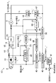
- FIG. 1 is a schematic circuit diagram of a power converter according to an embodiment.
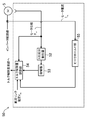
- FIG. 2 is a block diagram illustrating details of the control unit of the power conversion apparatus.
- FIG. 3 is a block diagram showing details of the torque control unit of the power converter.
- FIG. 1 is a schematic circuit diagram of a power converter according to an embodiment.
- FIG. 2 is a block diagram illustrating details of the control unit of the power conversion apparatus.
- FIG. 3 is a block diagram showing details of the torque control unit of the power converter.
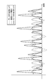
- FIG. 4 is a chart showing waveforms of the motor load torque, the DC link voltage,
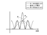
- FIG. 7 is a chart showing the waveforms of the motor load torque, DC link voltage, and motor output torque in the torque control operation, where the peak of the load torque and the peak of the DC link voltage match. is there.
- FIG. 8 is a chart for explaining the peak hold operation in the torque control operation.
- FIG. 9 is a chart for explaining a state in which the peak of the load torque of the motor and the peak of the DC link voltage are gradually shifted.
- FIG. 10 is a block diagram of the speed command correction unit.
- FIG. 10 is a block diagram of the speed command correction unit.
- FIG. 11 is a chart showing the beat generation period and the peak hold determination period, and shows a state in which no beat occurs in each determination period.
- FIG. 12 is a flowchart showing the control operation of the speed command correction unit.
- FIG. 13 is a chart showing a beat generation cycle and a peak hold determination cycle, and shows a state in which a beat occurs for each determination period.
- FIG. 14 is a chart showing an example of an increase in the DC link voltage accompanying the resonance between the reactor and the capacitor.
- FIG. 15 is a schematic circuit diagram of a power converter according to the first modification.
- FIG. 16 is a circuit diagram of a power converter according to the second modification.
- FIG. 17 is a circuit diagram of a power converter according to the third modification.
- FIG. 18 is a chart showing an example of fluctuations in compression torque.
- FIG. 19 is a block diagram illustrating a configuration of a control unit according to the second embodiment of the present invention.
- the power converter (10) is connected to a three-phase AC motor (5) of a compressor connected to a refrigerant circuit of an air conditioner, for example.
- the compressor is composed of a rotary compressor having one cylinder, for example. That is, in this compressor, when the drive shaft makes one rotation, the compression torque (that is, the load torque of the motor (5)) pulsates.
- the motor (5) is, for example, a 4-pole 6-slot concentrated winding DC brushless motor.
- the power conversion device (10) is configured to be able to execute a torque control operation for controlling the generated torque of the motor (5) and suppressing the vibration of the motor (5).
- the power conversion device (10) includes a converter circuit (11), a DC link unit (15), an inverter circuit (20), and a control unit (40).
- the power conversion device (10) converts AC power supplied from the single-phase AC power supply (6) into power of a predetermined frequency and supplies it to the motor (5).
- the converter circuit (11) is connected to the AC power source (6).
- the converter circuit (11) is a so-called diode bridge circuit in which a plurality (four in this embodiment) of diodes (D1 to D4) are connected in a bridge shape.
- the converter circuit (11) is a full-wave rectification circuit that full-wave rectifies the alternating current output from the alternating-current power supply (6) into direct current.
- the DC link unit (15) is connected in parallel to the output side of the converter circuit (11).
- a reactor (12) is connected between the converter circuit (11) and the DC link unit (15).
- the DC link part (15) has a capacitor (16).
- the DC voltage (DC link voltage Vdc) generated at both ends of the capacitor (16) is connected to the input node of the inverter circuit (20).
- the capacitor (16) is constituted by, for example, a film capacitor.
- the capacitor (16) is set to have a relatively small capacitance (for example, several tens of ⁇ F).
- the capacitor (16) has a ripple voltage (voltage) generated corresponding to the frequency of the switching operation when the switching element (Su, Sv, Sw, Sx, Sy, Sz) of the inverter circuit (20) operates.
- (Capacitance) can be smoothed.
- the capacitor (16) has a capacitance that cannot smooth the voltage rectified by the converter circuit (11) (voltage fluctuation caused by the power supply voltage).
- the DC link unit (15) receives the output of the converter circuit (11), and the DC link voltage Vdc having a pulsation having a frequency twice as high as the power supply voltage Vin of the AC power supply (6) from both ends of the capacitor (16). Is output.
- the DC link voltage Vdc output from the DC link unit (15) has a large pulsation such that the maximum value is twice or more the minimum value.
- the inverter circuit (20) constitutes a conversion unit, the input node is connected in parallel to the capacitor (16) of the DC link unit (15), and the output of the DC link unit (15) is switched to provide a three-phase AC And supply to the connected motor (5).
- the inverter circuit (20) of the present embodiment is configured by a plurality of switching elements being bridge-connected. Since this inverter circuit (20) outputs three-phase alternating current to the motor (5), it has six switching elements (Su, Sv, Sw, Sx, Sy, Sz).
- the inverter circuit (20) includes three switching legs in which two switching elements are connected in series with each other. In each switching leg, the switching elements of the upper arm (Su, Sv, Sw) and the lower arm are switched.
- the midpoints of the elements are respectively connected to coils (not shown) of each phase of the motor (5).
- free-wheeling diodes Du, Dv, Dw, Dx, Dy, Dz
- the inverter circuit (20) switches the DC link voltage (vdc) input from the DC link unit (15) by turning on and off these switching elements (Su, Sv, Sw, Sx, Sy, Sz). Convert to phase AC voltage and supply to motor (5).
- the power conversion device (10) includes various detection units. Specifically, the power converter (10) includes a power supply voltage detector (25) that detects a power supply voltage (Vin) of the AC power supply (6) and a power supply phase ( ⁇ in) of the power supply voltage of the AC power supply (6). The power supply phase detection unit (26) for detecting and the power supply frequency detection unit (27) for detecting the frequency (fin) of the power supply voltage of the AC power supply (6) are included.
- the power converter (10) includes an input current detector (28) that detects the input current (Iin) of the converter circuit (11) and a DC that detects the DC link voltage (Vdc) of the DC link unit (15). And a link voltage detector (29).
- the power conversion device (10) includes a motor current detection unit (30) that detects a current (Idq) flowing through the motor (5) (specifically, a current flowing through each phase of the motor (5)), a motor ( The motor phase detector (31) that detects the phase ( ⁇ m) of 5) and the motor rotation speed detector (32) that detects the actual rotational speed ( ⁇ m) of the motor (5) are provided.
- a motor current detection unit (30) that detects a current (Idq) flowing through the motor (5) (specifically, a current flowing through each phase of the motor (5))
- the motor phase detector (31) that detects the phase ( ⁇ m) of 5)
- the motor rotation speed detector (32) that detects the actual rotational speed ( ⁇ m) of the motor (5) are provided.
- the control unit (40) outputs a gate signal (G) for controlling switching (on / off operation) of the inverter circuit (20) to the inverter circuit (20).
- the control unit (40) of the present embodiment synthesizes the pulsating component of the power supply voltage with the output torque of the motor (5), and the output torque of the motor (5) according to the load torque fluctuation of the motor (5). A variable torque control operation is performed.
- control unit (40) includes a speed control unit (41), a torque control unit (50), a torque control superposition unit (42), a torque command modulation unit (43), and a secondary harmonic application unit. (44), an input current command generation unit (45), an amplifier (46), a limiter (60), a current control unit (47), and a PWM calculation unit (48).
- the deviation after the actual rotational speed ( ⁇ m) of the motor (5) is subtracted from the speed command ( ⁇ *) of the motor rotational speed in the subtractor (34) is input to the speed controller (41). .
- the speed controller (41) calculates the average (average torque) of the load torque of the motor (5) by performing proportional / integral calculation (PI calculation) on the deviation between the actual rotation speed ( ⁇ m) and the speed command ( ⁇ *). Is calculated.
- This average torque is an average value of load torque pulsating at a predetermined cycle.
- the speed control unit (41) outputs the average torque as a command value (average torque command value (Tave *)) to the torque control superimposing unit (42).
- the torque control superimposing unit (42) multiplies the average torque command value (Tave *) by a command value output from the torque control unit (50) described in detail later. As a result, the torque control superimposing unit (42) generates a torque command value (T *) obtained by synthesizing the pulsation component of the load torque of the motor (5).
- the command value generated by the torque control superimposing unit (42) is input to the torque command modulating unit (43).
- the torque command modulation unit (43) generates a sine value sin ⁇ in by using the phase angle (power supply phase ( ⁇ in)) of the AC power supply (6) as an input, and sets the modulation coefficient r corresponding to this to the torque command value (T *). Multiply and output to the secondary harmonic application unit (44).
- the secondary harmonic application unit (44) applies a frequency component twice the power supply frequency to the output value of the torque command modulation unit (43) so that the output power from the motor (5) is sinusoidal.
- the modulation coefficient r is, for example,
- the modulation coefficient r may be determined according to a sine value sin ( ⁇ in + ⁇ ) obtained by shifting the phase ( ⁇ in) by a predetermined amount ⁇ so that the output power of the motor (5) becomes a sine wave.
- the input current command generation unit (45) extracts the fundamental frequency component by Fourier transforming the input current (Iin), and multiplies it by sin ( ⁇ in) to obtain the input current command value (Iin *). Generate.
- This command value (Iin *) is output to the amplifier (46) after the absolute value (
- the output value from the secondary harmonic application unit (44) and the output value from the amplifier (46) are added in the adder (36).
- the command value after the addition is processed by a limiter (60) described later in detail, and then input to the subtracter (37).
- the subtractor (37) the actual motor current (Idq) is subtracted from the command value output from the limiter (60) side, and this value is output to the current control unit (47).
- the current control unit (47) generates a voltage command value (Vdq *) based on the current command value, and outputs the voltage command value (Vdq *) to the PWM calculation unit (48).
- the PWM calculation unit (48) generates a gate signal (G) for controlling the on / off operation of each switching element (Su, Sv, Sw, Sx, Sy, Sz) based on the voltage command value (Vdq *). Thereby, each switching element (Su, Sv, Sw, Sx, Sy, Sz) performs an on / off operation at a predetermined duty.
- the torque control unit (50) is for determining / outputting the control amount of the torque command described above based on the load torque of the motor (5) and the like. As shown in FIG. 3, the torque control unit (50) includes a primary component extractor (52), an amplifier (53), a torque control amount adjustment unit (54), and a peak hold unit (55).
- the primary component extractor (52) extracts a primary component (fundamental frequency component) that most influences the vibration of the motor (5) among the pulsating components of the load torque of the motor (5) by Fourier transform.
- the amplifier (53) multiplies the primary component extracted by the primary component extractor (52) by a predetermined gain, and outputs the result to the torque control amount adjustment unit (54).
- the torque control amount adjustment unit (54) outputs the command value multiplied by the above-described average torque command value (Tave *) to the torque control superimposing unit (42) as the final torque control amount. For this reason, a torque command value (T *) having a larger fluctuation range than the average torque command value (Tave *) is output from the torque control superimposing unit (42).
- the fluctuation range of the torque command value (T *) after multiplication is the same as the average torque command value (Tave *)
- the fluctuation range of the output torque of the motor (5) is the average value of the load torque (average Torque)
- the ratio of the fluctuation range of the output torque to the average torque at this time 100%.
- the torque control amount is 100% or more. Become. That is, in the present embodiment, during the torque control operation, the output torque of the motor (5) is adjusted so as to have a waveform including a fluctuation range larger than the average value of the load torque of the motor (5).
- the peak hold unit (55) shown in FIG. 3 constitutes a peak current deriving unit for deriving the peak current while holding the maximum value of the current (Idq) flowing through the motor (5) in a predetermined determination period.
- the torque control amount adjustment unit (54) adjusts the output command value so as to reduce the torque control amount.
- the torque control amount adjusting unit (54) limits the output command value of the torque control amount based on the DC link voltage (Vdc) detected by the DC link voltage detecting unit (29).
- a torque command value for generating an output torque for suppressing the load torque of the motor (5) is synthesized with the input command value of the current control unit (47).
- the DC link voltage (Vdc) pulsates with a cycle (Tdc), and the load torque of the motor (5) also pulsates with a cycle (Tc).
- the output torque is controlled so that the pulsation of the power supply voltage of the AC power supply (6) and the pulsation of the load torque are combined. Therefore, for example, at the timing when the peak of the DC link voltage (Vdc) and the peak of the load torque are relatively close, the output torque is also relatively large.
- the output torque of the motor (5) is controlled so as to be synchronized with the load torque, the speed fluctuation of the motor (5) is suppressed and the vibration of the motor (5) is reduced.
- the output torque of the motor (5) is controlled so as to suppress the fundamental frequency component of the load torque, which is the main cause of vibration, and thus the vibration of the motor (5) is effectively suppressed. be able to.
- Vdc DC link voltage
- the fluctuation range of the output torque is increased due to the increase of the torque control amount, and accordingly, the output torque is less than 0 and fluctuates to the minus side.
- the motor (5) performs a regenerative operation.
- the capacitance of the capacitor (16) of the DC link unit (15) is set to be extremely low. For this reason, when the motor (5) performs the regenerative operation in this way, the regenerative energy cannot be sufficiently absorbed by the capacitor (16), the DC link portion (15) becomes overvoltage, and the switching element (Su, (Sv, Sw, Sx, Sy, Sz) etc. may be destroyed. Therefore, in the present embodiment, as shown in FIG. 2, a limiter (60) is provided in the control unit (40) to limit the output torque from reaching minus torque.
- the limiter (60) generates a command value that limits the output torque on the negative side so that the output torque of the motor (5) does not reach a negative value with respect to the input command value.
- the output torque output torque indicated by the two-dot chain line in FIG. 6
- the regenerative operation of the motor (5) is surely prevented, and the switching elements (Su, Sv, Sw, Sx, Sy, Sz) and the like are protected.
- the control of the limiter (60) no limitation is imposed on the output torque on the plus side. For this reason, in the torque control operation, the output torque of the motor (5) can be sufficiently obtained, and the vibration of the motor (5) can be effectively suppressed.
- the limiter (60) is provided immediately before the input side of the current control unit (47), thereby reliably preventing the output torque from reaching the negative side.
- the limiter (60) may be provided at another location on the input side of the current control unit (47).
- the limiter (60) may be provided on the output side of the torque control amount adjusting unit (54) of the torque control unit (50).
- the current value of the motor (5) is appropriately detected, and the torque control amount of the torque control amount adjustment unit (54) is limited so that the current does not exceed a predetermined upper limit value.
- the DC link voltage (Vdc) pulsates at a predetermined frequency as described above, the timing of the peak (Pdc) of the DC link voltage (Vdc) and the peak (Pl) of the load torque is , Not necessarily coincident (see, eg, FIG. 4). For this reason, even if the current of the motor (5) is detected at the timing when the peaks (Pdc, Pl) of both are shifted, the current value becomes a relatively low value, and the desired peak current cannot be detected.
- the above-described peak hold unit (55) is provided in the control unit (40) of the present embodiment so that the peak current of the motor (5) can be reliably detected.
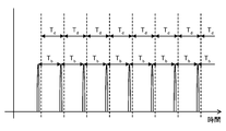
- the peak hold unit (55) controls the motor current detected by the motor current detection unit (30) (strictly speaking, the control period of the phase current of the motor (5)) for each predetermined determination period (Td). The maximum value of each peak value) is held. This point will be described more specifically with reference to FIG.
- the motor current is appropriately input to the peak hold unit (55).
- the peak hold unit (55) derives the maximum value of the motor current (that is, the peak current (Ip)) for each predetermined determination period (Td).
- the peak current (Ip) derived in the previous determination period is also retained in the next determination period (Td).
- the determination period (Td) is set to a time (for example, 1 second) that can sufficiently detect the timing at which both peaks (Pl, Pdc) coincide.
- the peak current (Ip) is updated. That is, in one determination period (Td), the peak current (Ip) is updated so as to trace the maximum value of the motor current as appropriate. Thereby, even when the average torque suddenly increases within the determination period (Td), the current peak can be detected quickly.
- the peak current (Ip) detected by the peak hold unit (55) is output to the torque control amount adjustment unit (54).
- the torque control amount adjustment unit (54) limits the torque control amount and reduces the output torque of the motor (5).
- the upper limit value of the peak current (Ip) is set to a predetermined value lower than the rated maximum allowable current value of the switching element (Su, Sv, Sw, Sx, Sy, Sz), for example.
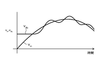
- FIG. 9 shows an example of the waveform of the DC link voltage (Vdc) and the waveform of the load torque of the motor (5).
- the timing of the peak (Pdc) of the DC link voltage (Vdc) and the peak (Pl) of the load torque of the motor (5) coincide at the time t1.
- the frequency (fdc) of the DC link voltage and the integer n times the frequency of the load torque that is, the operating frequency fc of the motor (5)
- the control unit (40) of the present embodiment is provided with a speed command correction unit (70) for reliably detecting the peak current (Ip) even under such conditions (see FIG. 10).
- the speed command correction unit (70) includes a beat cycle calculation unit (71) and a speed command adjustment unit (72).
- the beat cycle calculation unit (71) is a cycle of timing (hereinafter referred to as “the timing when the peak (Pdc) of the DC link voltage (Vdc) and the peak (Pl) of the load torque coincide with each other”. This constitutes a period deriving section for deriving the beat period (Tb).
- the speed command adjustment unit (72) corrects the speed command ( ⁇ *) of the motor (5) based on the beat cycle (Tb) derived by the beat cycle calculation unit (71), and the operating frequency of the motor (5) (Fc) is adjusted.
- the peak (Pdc) of the DC link voltage (Vdc) and the peak (Pl) of the load torque are matched during the determination period (Td). It is assumed that the beat cycle (Tb) is considerably longer than the determination period (Td) of the peak hold unit (55). Under such conditions, the peak current (Ip) cannot be reliably detected even if the above-described peak hold is performed.
- the speed command correction unit (70) performs control as shown in FIG.
- the beat period calculation unit (71) derives the pulsation frequency (fdc) of the DC link voltage (Vdc).
- the beat cycle calculation unit (71) has the highest frequency (fdc) of the pulsation of the DC link voltage (Vdc) and the integer multiple (n times) of the operating frequency (fc) of the motor (5).
- fdc the lowest frequency of the pulsation of the DC link voltage
- n the integer multiple (n times) of the operating frequency (fc) of the motor (5).
- step S3 the beat cycle calculation unit (71) calculates the frequency (beat frequency (fb)) at which the beat occurs according to the following equation (1).
- step S6 the speed command adjustment unit (72) calculates an operation frequency (fc *) for making the beat cycle (Tb) the same as the determination period (Td) by the following equation (2). .
- the pulsation frequency (fdc) of the DC link voltage (Vdc) is 100.2 Hz
- the judgment period (Td) is 1 sec.
- the speed command adjustment unit (72) inputs the speed command ( ⁇ *) so as to correct the current operation frequency (fc, for example, 25 Hz) to the calculated operation frequency (fc *, for example, 24.8 Hz). Correct.
- the beat cycle (Tb) and the determination period (Td) are the same period.
- the DC link voltage (Vdc) is determined for each determination period (Td).
- the peak current (Ip) can be derived by making the timing of the peak (Pdc) and the peak of the load torque (Pl) coincide with each other or substantially coincide with each other.
- the speed command adjustment unit (72) of the present embodiment ensures that the beat period (Tb) and the determination period (Td) are the same when the beat period (Tb) is greater than the determination period (Td).
- the operating frequency (fc) of the motor (5) is corrected.
- the speed command adjustment unit (72) operates the operating frequency (fc) so that the beat cycle (Tb) is smaller than the determination period (Td). May be corrected. That is, in the determination period (Td), the timing of the peak (Pdc) of the DC link voltage (Vdc) and the peak (Pl) of the load torque may be matched or substantially matched at least once.
- the torque control amount adjustment unit (54) corrects the torque control amount based on the peak of the DC link voltage (Vdc) during the half power cycle. Specifically, for example, when the peak of the DC link voltage (Vdc) in the half cycle of the power source exceeds a predetermined upper limit value, the torque control amount adjusting unit (54) is set so that the DC link unit (15) does not become an overvoltage. Reduce torque control amount. Thereby, in the torque control amount adjusting unit (54), the command value of the torque control amount is limited to a predetermined value (a command value that prevents the DC link voltage Vdc from becoming an overvoltage). As a result, resonance between the reactor (12) and the capacitor (16) as described above is suppressed, and an increase in the DC link voltage (Vdc) as shown in FIG. 14 is suppressed.
- a predetermined value a command value that prevents the DC link voltage Vdc from becoming an overvoltage
- the torque control amount adjustment unit (54) reduces the torque control amount.
- the command value of the torque control amount is limited to a predetermined value.
- the torque control amount adjustment unit (54) of the present embodiment limits the torque control amount based on the DC link voltage (Vdc) detected by the DC link voltage detection unit (29).
- the torque control amount may be limited in the same manner as described above.
- the limiter (60) limits the output torque so that the output torque of the motor (5) does not reach the negative side during the torque control operation (see FIG. 6). For this reason, the regenerative operation of the motor (5) can be reliably prevented, and the switching elements (Su, Sv, Sw, Sx, Sy, Sz) and the like can be reliably protected.
- the maximum value of the current of the motor (5) is held by the peak hold unit (55), and the peak current (Ip) is derived (FIG. 8). reference. For this reason, it becomes easy to derive the motor current value when the peak of the output torque coincides with the peak of the DC link voltage (Vdc) as the peak current (Ip).
- the switching element Su, Sv, Sw, Sx, Sy, Sz
- the like can be reliably protected by reducing the fluctuation range of the output torque.
- the beat cycle (Pdc) and the peak of the load torque (Pl) do not easily coincide with the beat cycle (Pd)
- the operating frequency of the motor (5) is adjusted so that the Tb) and the determination period (Td) are the same. Therefore, for example, as shown in FIG. 13, the peak current (Ip) can be derived by surely matching the peaks (Pdc, Pl) of the two for each determination period (Td).
- the control amount of the output torque is limited to the predetermined value.
- the control amount of the output torque is limited to a predetermined value.
- FIG. 19 is a block diagram illustrating a configuration of the torque control unit (50) according to the second embodiment of the present invention.
- the torque control unit (50) of the present embodiment includes a peak current value estimation unit (80) instead of the peak hold unit (55) in the torque control unit (50) of the first embodiment.
- An average torque command value (Tave * ) is input to the peak current value estimation unit (80).
- the torque control unit (50) estimates the peak current value by the peak current value estimation unit (80), and outputs the motor (5) so that the estimated peak current value does not exceed a predetermined upper limit value. Reduce the fluctuation range of torque.
- the output value of the second harmonic applying unit (44) of Embodiment 1 is Idq1 *, and the relationship between the average torque command value (Tave * ), the torque command value (T * ), and the output value (Idq1 * ) Is expressed by the following equation.
- T * CT ⁇ Tave *
- CT is a fluctuation component caused by load torque fluctuation
- CV is a fluctuation component caused by voltage pulsation.
- the magnitude of the output value (Idq1 * ) changes due to the two fluctuation components. Since the output value (Idq1 * ) represents the magnitude of the motor current, if the peak value of this output value (Idq1 * ) is known, the peak current value during torque control in the inverter circuit (20) can be estimated. it can.
- CT 1 + kT ⁇ sin ( ⁇ m) kT: Torque control amount
- ⁇ m Motor phase (mechanical angle)
- CV kV ⁇
- Idq1 * the maximum value because the phase ( ⁇ m) and power supply phase ( ⁇ in) are 90 ° respectively.
- the peak current value estimation unit (80) obtains the peak current value based on the above relational expression. As described above, once the peak current value is obtained, the fluctuation range of the output torque of the motor (5) is reduced so that the peak current value does not exceed the predetermined upper limit value. It becomes possible to obtain the effect.
- the single-phase AC power source (6) is used as the power source.
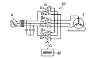
- the present invention is not limited to this, and a three-phase AC power source can be used as in the example shown in FIG. 15 (Modification 1). .
- the converter circuit (11) shown in FIG. 15 is a diode bridge circuit in which six diodes (D1 to D6) are connected in a bridge shape.
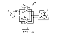
- the said embodiment is intended for the power converter device containing a converter circuit (11) and an inverter circuit (20), it is not restricted to this, For example, it shows in the example (modification 2) shown in FIG. 16, and FIG.
- the matrix converter (20) as in the example (Modification 3) can also be targeted.
- These matrix converters (20) constitute a conversion unit that converts electric power from the AC power source (6) into AC power having a predetermined frequency.
- a transistor etc. can be used for the switching element (Sr, Ss, St, Su, Sv, Sw, Sx, Sy, Sz) of the matrix converter (20).
- the present invention is useful for a power converter that controls the torque of a motor.
Landscapes
- Engineering & Computer Science (AREA)
- Power Engineering (AREA)
- Control Of Ac Motors In General (AREA)
- Inverter Devices (AREA)
- Control Of Motors That Do Not Use Commutators (AREA)
Abstract
Description
本発明に係る電力変換装置(10)は、例えば空気調和装置の冷媒回路に接続される圧縮機の三相交流式のモータ(5)に接続される。圧縮機は、例えば1つのシリンダを有するロータリー式の圧縮機で構成される。つまり、この圧縮機では、駆動軸が1回転する際に、圧縮トルク(即ち、モータ(5)の負荷トルク)が脈動する。また、モータ(5)は、例えば4極6スロットの集中巻きのDCブラシレス式のモータである。後述するように、電力変換装置(10)では、このモータ(5)の発生トルクを制御してモータ(5)の振動を抑制するトルク制御動作を実行可能に構成されている。
図1に示すように、電力変換装置(10)は、コンバータ回路(11)、直流リンク部(15)、インバータ回路(20)、及び制御部(40)を有している。電力変換装置(10)は、単相の交流電源(6)から供給された交流の電力を所定の周波数の電力に変換して、モータ(5)に供給する。
図2に示すように、制御部(40)は、速度制御部(41)、トルク制御部(50)、トルク制御重畳部(42)、トルク指令変調部(43)、2次調波印加部(44)、入力電流指令生成部(45)、増幅器(46)、リミッタ(60)、電流制御部(47)、及びPWM演算部(48)を備えている。
トルク制御部(50)は、モータ(5)の負荷トルク等に基づいて、上述したトルク指令の制御量を決定/出力するためのものである。図3に示すように、トルク制御部(50)は、1次成分抽出器(52)、増幅器(53)、トルク制御量調整部(54)、及びピークホールド部(55)を備えている。
トルク制御動作について、より具体的に説明する。上述した電流制御部(47)の入力指令値には、モータ(5)の負荷トルクを抑制する出力トルクを発生させるためのトルク指令値が合成される。これにより、トルク制御動作時には、例えば図4に示すようにして、モータ(5)の出力トルクが制御される。なお、図4は、交流電源(6)の電源周波数fin=50Hz,モータ(5)の回転速度=30rps、トルク制御量=100%の条件下における、モータ(5)の負荷トルク、直流リンク部(15)から出力される直流リンク電圧(Vdc)、及びモータ(5)の出力トルクの経時変化を表したものである。
上記のようなトルク制御動作においては、モータ(5)の振動の一次成分を抑制するためにトルク制御量が100%以上となる。このため、このトルク制御では、モータ(5)の出力トルクの変動幅(振幅)が大きく成り易い。従って、このようにして出力トルクの振幅が大きくなり、出力トルクがマイナス側に至ると、モータ(5)が回生動作を行ってしまう可能性がある。
上述したトルク制御動作時には、モータ(5)の出力トルクの増大に起因して、モータ(5)の電流(Idq)が高くなる。具体的には、例えば図7に示すように、モータ(5)の負荷トルクのピーク(図7の2点鎖線で示すピーク(Pl))と、直流リンク電圧(Vdc)のピーク(図7の白抜きの点で示すピーク(Pdc))とのタイミングが一致もしくは略一致すると、これに伴いモータ(5)の出力トルクが極めて大きくなる。よって、これらの両者のピーク(Pl,Pdc)のタイミングが一致した場合に、モータ(5)の電流が急上昇する。このようにして、モータ(5)の電流が急峻に上昇すると、スイッチング素子(Su,Sv,Sw,Sx,Sy,Sz)の電流値が定格の最大許容電流値を越えてスイッチング素子(Su,Sv,Sw,Sx,Sy,Sz)の破壊を招いたり、モータ(5)の磁石の減磁を招いたりする。また、このような対策としてデバイスの電流容量を大きくすると、電力変換装置(10)のコストアップを招く。
上述のように、ピークホールド部(55)によって判定期間(Td)毎にモータ電流のピーク電流(Ip)を保持したとしても、この判定期間(Td)をあまりにも長くすると、トルク制御量の制御性が悪化してしまうことがある。具体的には、例えば判定期間(Td)内においてピーク電流(Ip)が保持された後、この判定期間(Td)中に平均トルクが下がった場合、実際にはトルク制御量をもう少し大きくすることができるのに、上記のようにトルク制御量が制限されてしまい、トルク制御性能の悪化を招く。
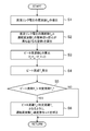
次いで、ステップS4において、ビート周期演算部(71)は、算出したビート周波数(fb)の逆数を求めてビート周期(Tb)を算出する。算出された直流リンク電圧の周波数(fdc)が100.2Hzであり、モータ(5)の運転周波数(fc)が25Hzであり、整数nは4であったとすると、ビート周波数(fb)は、上記(1)式により100.2Hz-25Hz×4=0.2Hzとなり、ビート周期(Tb)は5secとなる。
例えば直流リンク電圧(Vdc)の脈動の周波数(fdc)が100.2Hzであり、判定期間(Td)が1secであり、整数nが4であったとすると、ビート周期(Tb)と判定期間(Td)とを同じとするための運転周波数(fc*)は、上記(2)式により(100.2Hz-1.0Hz)/4=24.8Hzとなる。そこで、速度指令調整部(72)は、現在の運転周波数(fc、例えば25Hz)を算出後の運転周波数(fc*、例えば24.8Hz)に補正するように、入力された速度指令(ω*)を補正する。これにより、その後の運転では、ビート周期(Tb)と判定期間(Td)とが同じ周期となるため、例えば図13に示すように、各判定期間(Td)毎に、直流リンク電圧(Vdc)のピーク(Pdc)と負荷トルクのピーク(Pl)とのタイミングを必ず一度は一致もしくは略一致させてピーク電流(Ip)を導出することができる。
トルク制御動作時において、交流電源(6)の電源電圧(Vin)が比較的高い条件、あるいは低い条件下において、出力トルクが過剰になると、不具合を招く虞がある。具体的に、電源電圧(Vin)が比較的高く、これに伴い直流リンク電圧(Vdc)も比較的高い条件下において、トルク制御量が比較的大きい場合、リアクタ(12)とコンデンサ(16)との共振が大きくなり、直流リンク電圧(Vdc)が過剰に高くなってしまうことがある(例えば図14を参照)。また、電源電圧(Vin)が比較的低く、これに伴い直流リンク電圧(Vdc)も比較的低い条件下において、トルク制御量が比較的大きい場合にも、所望の出力トルクを得ようとするためにPWM演算部(48)のパルス信号のデューティーが全体的に高くなってしまう。その結果、電流制御の追従性が遅くなりトルク制御動作の制御性が悪化してしまう虞がある。
上記実施形態によれば、トルク制御動作時に、モータ(5)の出力トルクがマイナス側に至らないようにリミッタ(60)が出力トルクを制限している(図6を参照)。このため、モータ(5)の回生動作を確実に防止でき、スイッチング素子(Su,Sv,Sw,Sx,Sy,Sz)等を確実に保護できる。
図19は、本発明の実施形態2に係るトルク制御部(50)の構成を示すブロック図である。本実施形態のトルク制御部(50)は、実施形態1のトルク制御部(50)におけるピークホールド部(55)に代えて、ピーク電流値推定部(80)を備えている。ピーク電流値推定部(80)には、平均トルク指令値(Tave*)が入力されている。トルク制御部(50)は、ピーク電流値推定部(80)によって上記ピーク電流の値を推定し、推定したピーク電流の値が所定の上限値を超えないように、上記モータ(5)の出力トルクの変動幅を低減させる。
Idq1*= CV ×T* = CV × CT × Tave*
CTは負荷トルク変動に起因する変動成分であり、CVは電圧脈動に起因する変動成分である。上記2つの変動成分により、出力値(Idq1*)の大きさは変化することになる。出力値(Idq1*)はモータ電流の大きさを表しているので、この出力値(Idq1*)のピーク値が分かれば、インバータ回路(20)におけるトルク制御時のピーク電流値を推定することができる。
CT=1+kT×sin(θm)
kT:トルク制御量,θm :モータ位相(機械角)
CV=kV×|sin(θin)|
kV:電圧脈動成分の変動量,θin :電源電圧の位相
のように構成すると、出力値(Idq1*)が最大値をとるのは、位相(θm)、電源位相(θin)それぞれが、90°もしくは270°のときであり、その最大値は、
Idq1*=kV ×(1+kT)×Tave
となる。したがって、kV、kT、Taveが決まれば、ビート状に変動するモータ電流のピーク値を推定することができる。
上記実施形態では、電源として単相の交流電源(6)を用いているが、この限りでなく、図15に示す例(変形例1)のように、三相の交流電源を用いることもできる。図15に示すコンバータ回路(11)は、6つのダイオード(D1~D6)がブリッジ状に結線されたダイオードブリッジ回路である。
6 交流電源
10 電力変換装置
11 コンバータ回路
15 直流リンク部
16 コンデンサ
20 インバータ回路
21 コンデンサ
40 制御部
54 トルク制御量調整部
55 ピークホールド部
60 リミッタ(制限部)
71 ビート周期演算部(周期導出部)
72 速度指令調整部
Claims (6)
- 複数のスイッチング素子(Sr,Ss,St,Su,Sv,Sw,Sx,Sy,Sz)を有し、交流電源(6)側からの電力を前記複数のスイッチング素子(Sr,Ss,St,Su,Sv,Sw,Sx,Sy,Sz)のスイッチング動作によって所定の周波数の交流電力に変換し、該交流電力をモータ(5)に出力する変換部(20)と、
上記モータ(5)の出力トルクが、上記交流電源(6)の出力電圧の周波数の整数倍の脈動成分である電源脈動成分を含み、且つ上記モータ(5)の負荷トルク変動に応じて変動するようにトルク制御動作を行うとともに、上記電源脈動成分のピークと上記負荷トルク変動成分のピークとタイミングが一致もしくは略一致したときのピーク電流値を求め、該ピーク電流値が所定の上限値を超えないように、上記出力トルクの変動幅を低減させる制御部(40)と、
を備えていることを特徴とする電力変換装置。 - 請求項1において、
上記制御部(40)は、所定の判定時間において上記ピーク電流値を保持するピークホールド部(55)と、該ピークホールド部(55)で保持されたピーク電流値が所定の上限値を越えると、上記モータ(5)の出力トルクの変動幅を低減させるトルク制御量調整部(54)とを備えていることを特徴とする電力変換装置。 - 請求項2において、
上記制御部(40)は、上記ピークホールド部(55)の判定期間中に、上記負荷トルクの脈動成分のピークと上記電源脈動成分のピークとのタイミングが一致もしくは略一致するように、上記モータ(5)の運転周波数(fc)を補正する速度指令調整部(72)を備えていることを特徴とする電力変換装置。 - 請求項2又は3において、
上記制御部(40)は、上記交流電源(6)の出力電圧の周波数と、上記モータ(5)の運転周波数とに基づいて、上記モータ(5)の負荷トルクのピークと上記交流電源(6)の出力電圧のピークとが一致もしくは略一致するタイミングが存在する周期を導出する周期導出部(71)を備え、
上記速度指令調整部(72)は、上記周期導出部(71)で導出される周期が、上記ピークホールド部(55)の判定期間以下となるように、上記モータ(5)の運転周波数を補正することを特徴とする電力変換装置。 - 請求項1において、
上記制御部(40)は、上記ピーク電流値を推定し、推定したピーク電流値が所定の上限値を超えないように、上記モータ(5)の出力トルクの変動幅を低減させることを特徴とする電力変換装置。 - 請求項1において、
上記交流電源(6)からの電圧を整流するコンバータ回路(11)と、
上記コンバータ回路(11)の出力に並列に接続されるコンデンサ(16)を有する直流リンク部(15)と、
上記直流リンク部(15)からの出力電圧を交流電圧に変換し、該交流電圧をモータ(5)に上記変換部としてのインバータ回路(20)とを備え、
上記コンデンサ(16)の容量値は、上記インバータ回路(20)の入力電圧が大きく脈動するような値に設定されていることを特徴とする電力変換装置。
Priority Applications (6)
| Application Number | Priority Date | Filing Date | Title |
|---|---|---|---|
| KR1020137021309A KR101528691B1 (ko) | 2011-01-18 | 2011-12-28 | 전력 변환 장치 |
| RU2013138458/07A RU2543503C1 (ru) | 2011-01-18 | 2011-12-28 | Устройство преобразования мощности |
| CN201180065062.5A CN103299539B (zh) | 2011-01-18 | 2011-12-28 | 功率转换装置 |
| EP11856054.9A EP2667501B1 (en) | 2011-01-18 | 2011-12-28 | Power conversion apparatus |
| ES11856054T ES2816386T3 (es) | 2011-01-18 | 2011-12-28 | Aparato de conversión de energía |
| BR112013017904-0A BR112013017904B1 (pt) | 2011-01-18 | 2011-12-28 | método para controlar um aparelho de conversão de energia |
Applications Claiming Priority (2)
| Application Number | Priority Date | Filing Date | Title |
|---|---|---|---|
| JP2011007775 | 2011-01-18 | ||
| JP2011-007775 | 2011-01-18 |
Publications (1)
| Publication Number | Publication Date |
|---|---|
| WO2012098628A1 true WO2012098628A1 (ja) | 2012-07-26 |
Family
ID=46515281
Family Applications (1)
| Application Number | Title | Priority Date | Filing Date |
|---|---|---|---|
| PCT/JP2011/007364 Ceased WO2012098628A1 (ja) | 2011-01-18 | 2011-12-28 | 電力変換装置 |
Country Status (8)
| Country | Link |
|---|---|
| EP (1) | EP2667501B1 (ja) |
| JP (1) | JP5126409B2 (ja) |
| KR (1) | KR101528691B1 (ja) |
| CN (1) | CN103299539B (ja) |
| BR (1) | BR112013017904B1 (ja) |
| ES (1) | ES2816386T3 (ja) |
| RU (1) | RU2543503C1 (ja) |
| WO (1) | WO2012098628A1 (ja) |
Cited By (2)
| Publication number | Priority date | Publication date | Assignee | Title |
|---|---|---|---|---|
| JP2014027804A (ja) * | 2012-07-27 | 2014-02-06 | Daikin Ind Ltd | 電力変換装置 |
| JP2018029465A (ja) * | 2015-09-14 | 2018-02-22 | ダイキン工業株式会社 | インバータ基板、接続順序の判断方法 |
Families Citing this family (15)
| Publication number | Priority date | Publication date | Assignee | Title |
|---|---|---|---|---|
| JP5712987B2 (ja) * | 2012-09-27 | 2015-05-07 | ダイキン工業株式会社 | 電力変換装置の制御方法 |
| JP6079353B2 (ja) * | 2013-03-25 | 2017-02-15 | 株式会社富士通ゼネラル | Dcブラシレスモータの制御装置 |
| JP6274287B1 (ja) | 2016-09-30 | 2018-02-07 | ダイキン工業株式会社 | 電流推定装置 |
| JP6343037B1 (ja) * | 2017-01-11 | 2018-06-13 | 日立ジョンソンコントロールズ空調株式会社 | モータ駆動装置および冷凍機器 |
| EP4231517B1 (en) * | 2017-09-29 | 2025-02-12 | Daikin Industries, Ltd. | Power conversion device |
| JP6521131B1 (ja) * | 2018-03-29 | 2019-05-29 | ダイキン工業株式会社 | 電力変換装置 |
| JP6849000B2 (ja) * | 2019-03-14 | 2021-03-24 | ダイキン工業株式会社 | 直接形の電力変換装置 |
| CN109995305B (zh) * | 2019-04-26 | 2020-11-10 | 深圳和而泰智能控制股份有限公司 | 压缩机的力矩输入控制方法、装置、设备和冰箱 |
| US11557996B1 (en) * | 2021-07-08 | 2023-01-17 | Tula eTechnology, Inc. | Methods of reducing vibrations for electric motors |
| US11916498B2 (en) | 2021-09-08 | 2024-02-27 | Tule eTechnology Inc. | Electric machine torque adjustment based on waveform integer multiples |
| WO2023069131A1 (en) | 2021-10-18 | 2023-04-27 | Tula eTechnology, Inc. | Mechanical and electromechanical arrangements for field-weakening of an electric machine that utilizes permanent magnets |
| KR20250034022A (ko) | 2022-07-08 | 2025-03-10 | 툴라 이테크놀로지 아이엔씨. | 전기 기계 구동 교정, 검증 및 효율 개선 |
| US11888424B1 (en) | 2022-07-18 | 2024-01-30 | Tula eTechnology, Inc. | Methods for improving rate of rise of torque in electric machines with stator current biasing |
| CN120982009A (zh) * | 2023-03-31 | 2025-11-18 | 大金工业株式会社 | 电力供给装置 |
| EP4507187A1 (en) * | 2023-08-07 | 2025-02-12 | Thermo King LLC | A method of operating a motor coupled to a mechanical load |
Citations (5)
| Publication number | Priority date | Publication date | Assignee | Title |
|---|---|---|---|---|
| JPH10150777A (ja) * | 1996-11-19 | 1998-06-02 | Hitachi Ltd | インバータの制御装置 |
| JP2002051589A (ja) | 2000-07-31 | 2002-02-15 | Isao Takahashi | モータ駆動用インバータの制御装置 |
| JP2005046000A (ja) | 1996-08-19 | 2005-02-17 | Daikin Ind Ltd | 同期モータ駆動方法、圧縮機駆動方法およびこれらの装置 |
| JP2007028793A (ja) * | 2005-07-15 | 2007-02-01 | Hitachi Ltd | 交流モータ駆動装置及びその制御方法 |
| JP2008061409A (ja) * | 2006-08-31 | 2008-03-13 | Daikin Ind Ltd | モータ制御装置 |
Family Cites Families (13)
| Publication number | Priority date | Publication date | Assignee | Title |
|---|---|---|---|---|
| SU1259428A1 (ru) * | 1984-12-26 | 1986-09-23 | Криворожский Ордена Трудового Красного Знамени Горнорудный Институт | Вентильный электродвигатель |
| RU2073759C1 (ru) * | 1994-01-26 | 1997-02-20 | Акционерная компания "Туламашзавод" | Универсальный электропривод для швейных машин |
| US5471127A (en) * | 1994-05-04 | 1995-11-28 | Energy Reduction International Ltd. | Induction motor control |
| US6525497B2 (en) * | 2000-05-18 | 2003-02-25 | Lg Electronics Inc. | Phase distortion compensating apparatus and method for reducing torque ripple in 3-phase motor |
| JP4065375B2 (ja) * | 2001-11-20 | 2008-03-26 | 松下電器産業株式会社 | モータ駆動装置及びモータ駆動方法 |
| US6984953B2 (en) * | 2003-01-20 | 2006-01-10 | International Rectifier Corporation | Method and apparatus for reconstructing motor current from DC bus current |
| JP4575704B2 (ja) * | 2003-04-22 | 2010-11-04 | パナソニック株式会社 | モータ制御装置、圧縮機、空気調和機、及び冷蔵庫 |
| JP4552466B2 (ja) * | 2004-03-12 | 2010-09-29 | 株式会社日立製作所 | 交流モータの制御装置,2チップインバータ及びワンチップインバータ。 |
| JP2007060866A (ja) * | 2005-08-26 | 2007-03-08 | Mitsubishi Electric Corp | 車載用電動機制御装置 |
| WO2007108185A1 (ja) * | 2006-03-15 | 2007-09-27 | Mitsubishi Electric Corporation | 電動機駆動装置及び圧縮機駆動装置 |
| JP4971750B2 (ja) * | 2006-10-31 | 2012-07-11 | 株式会社日立製作所 | 電源回路、及びこれに用いる制御回路 |
| RU2396696C2 (ru) * | 2008-07-29 | 2010-08-10 | Государственное образовательное учреждение Высшего профессионального образования Липецкий государственный технический университет (ГОУ ВПО ЛГТУ) | Электропривод переменного тока |
| RU82077U1 (ru) * | 2008-12-05 | 2009-04-10 | Открытое Акционерное Общество "Агрегатное Конструкторское Бюро "Якорь" | Электропривод |
-
2011
- 2011-12-28 KR KR1020137021309A patent/KR101528691B1/ko active Active
- 2011-12-28 BR BR112013017904-0A patent/BR112013017904B1/pt active IP Right Grant
- 2011-12-28 WO PCT/JP2011/007364 patent/WO2012098628A1/ja not_active Ceased
- 2011-12-28 EP EP11856054.9A patent/EP2667501B1/en active Active
- 2011-12-28 ES ES11856054T patent/ES2816386T3/es active Active
- 2011-12-28 JP JP2011289373A patent/JP5126409B2/ja active Active
- 2011-12-28 RU RU2013138458/07A patent/RU2543503C1/ru active
- 2011-12-28 CN CN201180065062.5A patent/CN103299539B/zh active Active
Patent Citations (6)
| Publication number | Priority date | Publication date | Assignee | Title |
|---|---|---|---|---|
| JP2005046000A (ja) | 1996-08-19 | 2005-02-17 | Daikin Ind Ltd | 同期モータ駆動方法、圧縮機駆動方法およびこれらの装置 |
| JPH10150777A (ja) * | 1996-11-19 | 1998-06-02 | Hitachi Ltd | インバータの制御装置 |
| JP2002051589A (ja) | 2000-07-31 | 2002-02-15 | Isao Takahashi | モータ駆動用インバータの制御装置 |
| JP2007028793A (ja) * | 2005-07-15 | 2007-02-01 | Hitachi Ltd | 交流モータ駆動装置及びその制御方法 |
| JP2008061409A (ja) * | 2006-08-31 | 2008-03-13 | Daikin Ind Ltd | モータ制御装置 |
| JP4192979B2 (ja) | 2006-08-31 | 2008-12-10 | ダイキン工業株式会社 | モータ制御装置 |
Cited By (3)
| Publication number | Priority date | Publication date | Assignee | Title |
|---|---|---|---|---|
| JP2014027804A (ja) * | 2012-07-27 | 2014-02-06 | Daikin Ind Ltd | 電力変換装置 |
| JP2018029465A (ja) * | 2015-09-14 | 2018-02-22 | ダイキン工業株式会社 | インバータ基板、接続順序の判断方法 |
| JP7005251B2 (ja) | 2015-09-14 | 2022-01-21 | ダイキン工業株式会社 | 接続順序の判断方法 |
Also Published As
| Publication number | Publication date |
|---|---|
| BR112013017904B1 (pt) | 2020-12-29 |
| JP5126409B2 (ja) | 2013-01-23 |
| KR20130103808A (ko) | 2013-09-24 |
| EP2667501A4 (en) | 2017-07-26 |
| KR101528691B1 (ko) | 2015-06-12 |
| CN103299539B (zh) | 2016-05-18 |
| ES2816386T3 (es) | 2021-04-05 |
| CN103299539A (zh) | 2013-09-11 |
| EP2667501A1 (en) | 2013-11-27 |
| BR112013017904A2 (pt) | 2016-10-11 |
| EP2667501B1 (en) | 2020-08-05 |
| RU2013138458A (ru) | 2015-02-27 |
| JP2012165631A (ja) | 2012-08-30 |
| RU2543503C1 (ru) | 2015-03-10 |
Similar Documents
| Publication | Publication Date | Title |
|---|---|---|
| JP5126409B2 (ja) | 電力変換装置 | |
| CN103329413B (zh) | 功率转换装置 | |
| JP3699663B2 (ja) | インバータ制御方法およびその装置 | |
| JP5212491B2 (ja) | 電力変換装置 | |
| CN111919375B (zh) | 功率转换装置 | |
| JP6849000B2 (ja) | 直接形の電力変換装置 | |
| JP5673118B2 (ja) | 電力変換装置 | |
| JP5961949B2 (ja) | 電力変換装置 | |
| JP5741000B2 (ja) | 電力変換装置 | |
| JP6024262B2 (ja) | 電力変換装置 | |
| JP5838554B2 (ja) | 電力変換装置 | |
| JP5922869B2 (ja) | 電力変換装置 | |
| JP6384060B2 (ja) | 電力変換装置 | |
| JP6435956B2 (ja) | 電力変換装置 | |
| JP2024164998A (ja) | 電力変換装置 |
Legal Events
| Date | Code | Title | Description |
|---|---|---|---|
| 121 | Ep: the epo has been informed by wipo that ep was designated in this application |
Ref document number: 11856054 Country of ref document: EP Kind code of ref document: A1 |
|
| NENP | Non-entry into the national phase |
Ref country code: DE |
|
| WWE | Wipo information: entry into national phase |
Ref document number: 2011856054 Country of ref document: EP |
|
| ENP | Entry into the national phase |
Ref document number: 20137021309 Country of ref document: KR Kind code of ref document: A |
|
| ENP | Entry into the national phase |
Ref document number: 2013138458 Country of ref document: RU Kind code of ref document: A |
|
| REG | Reference to national code |
Ref country code: BR Ref legal event code: B01A Ref document number: 112013017904 Country of ref document: BR |
|
| ENP | Entry into the national phase |
Ref document number: 112013017904 Country of ref document: BR Kind code of ref document: A2 Effective date: 20130712 |