WO2012098806A1 - 照明用開口絞り - Google Patents
照明用開口絞り Download PDFInfo
- Publication number
- WO2012098806A1 WO2012098806A1 PCT/JP2011/079901 JP2011079901W WO2012098806A1 WO 2012098806 A1 WO2012098806 A1 WO 2012098806A1 JP 2011079901 W JP2011079901 W JP 2011079901W WO 2012098806 A1 WO2012098806 A1 WO 2012098806A1
- Authority
- WO
- WIPO (PCT)
- Prior art keywords
- light
- region
- aperture stop
- filter
- illumination
- Prior art date
- Legal status (The legal status is an assumption and is not a legal conclusion. Google has not performed a legal analysis and makes no representation as to the accuracy of the status listed.)
- Ceased
Links
Images







Classifications
-
- F—MECHANICAL ENGINEERING; LIGHTING; HEATING; WEAPONS; BLASTING
- F21—LIGHTING
- F21V—FUNCTIONAL FEATURES OR DETAILS OF LIGHTING DEVICES OR SYSTEMS THEREOF; STRUCTURAL COMBINATIONS OF LIGHTING DEVICES WITH OTHER ARTICLES, NOT OTHERWISE PROVIDED FOR
- F21V13/00—Producing particular characteristics or distribution of the light emitted by means of a combination of elements specified in two or more of main groups F21V1/00 - F21V11/00
- F21V13/02—Combinations of only two kinds of elements
-
- A—HUMAN NECESSITIES
- A61—MEDICAL OR VETERINARY SCIENCE; HYGIENE
- A61B—DIAGNOSIS; SURGERY; IDENTIFICATION
- A61B1/00—Instruments for performing medical examinations of the interior of cavities or tubes of the body by visual or photographical inspection, e.g. endoscopes; Illuminating arrangements therefor
- A61B1/04—Instruments for performing medical examinations of the interior of cavities or tubes of the body by visual or photographical inspection, e.g. endoscopes; Illuminating arrangements therefor combined with photographic or television appliances
- A61B1/043—Instruments for performing medical examinations of the interior of cavities or tubes of the body by visual or photographical inspection, e.g. endoscopes; Illuminating arrangements therefor combined with photographic or television appliances for fluorescence imaging
-
- A—HUMAN NECESSITIES
- A61—MEDICAL OR VETERINARY SCIENCE; HYGIENE
- A61B—DIAGNOSIS; SURGERY; IDENTIFICATION
- A61B1/00—Instruments for performing medical examinations of the interior of cavities or tubes of the body by visual or photographical inspection, e.g. endoscopes; Illuminating arrangements therefor
- A61B1/06—Instruments for performing medical examinations of the interior of cavities or tubes of the body by visual or photographical inspection, e.g. endoscopes; Illuminating arrangements therefor with illuminating arrangements
- A61B1/0638—Instruments for performing medical examinations of the interior of cavities or tubes of the body by visual or photographical inspection, e.g. endoscopes; Illuminating arrangements therefor with illuminating arrangements providing two or more wavelengths
-
- A—HUMAN NECESSITIES
- A61—MEDICAL OR VETERINARY SCIENCE; HYGIENE
- A61B—DIAGNOSIS; SURGERY; IDENTIFICATION
- A61B1/00—Instruments for performing medical examinations of the interior of cavities or tubes of the body by visual or photographical inspection, e.g. endoscopes; Illuminating arrangements therefor
- A61B1/06—Instruments for performing medical examinations of the interior of cavities or tubes of the body by visual or photographical inspection, e.g. endoscopes; Illuminating arrangements therefor with illuminating arrangements
- A61B1/0646—Instruments for performing medical examinations of the interior of cavities or tubes of the body by visual or photographical inspection, e.g. endoscopes; Illuminating arrangements therefor with illuminating arrangements with illumination filters
-
- A—HUMAN NECESSITIES
- A61—MEDICAL OR VETERINARY SCIENCE; HYGIENE
- A61B—DIAGNOSIS; SURGERY; IDENTIFICATION
- A61B1/00—Instruments for performing medical examinations of the interior of cavities or tubes of the body by visual or photographical inspection, e.g. endoscopes; Illuminating arrangements therefor
- A61B1/06—Instruments for performing medical examinations of the interior of cavities or tubes of the body by visual or photographical inspection, e.g. endoscopes; Illuminating arrangements therefor with illuminating arrangements
- A61B1/0661—Endoscope light sources
- A61B1/0669—Endoscope light sources at proximal end of an endoscope
-
- A—HUMAN NECESSITIES
- A61—MEDICAL OR VETERINARY SCIENCE; HYGIENE
- A61N—ELECTROTHERAPY; MAGNETOTHERAPY; RADIATION THERAPY; ULTRASOUND THERAPY
- A61N5/00—Radiation therapy
- A61N5/06—Radiation therapy using light
-
- F—MECHANICAL ENGINEERING; LIGHTING; HEATING; WEAPONS; BLASTING
- F21—LIGHTING
- F21V—FUNCTIONAL FEATURES OR DETAILS OF LIGHTING DEVICES OR SYSTEMS THEREOF; STRUCTURAL COMBINATIONS OF LIGHTING DEVICES WITH OTHER ARTICLES, NOT OTHERWISE PROVIDED FOR
- F21V9/00—Elements for modifying spectral properties, polarisation or intensity of the light emitted, e.g. filters
- F21V9/08—Elements for modifying spectral properties, polarisation or intensity of the light emitted, e.g. filters for producing coloured light, e.g. monochromatic; for reducing intensity of light
-
- G—PHYSICS
- G01—MEASURING; TESTING
- G01N—INVESTIGATING OR ANALYSING MATERIALS BY DETERMINING THEIR CHEMICAL OR PHYSICAL PROPERTIES
- G01N21/00—Investigating or analysing materials by the use of optical means, i.e. using sub-millimetre waves, infrared, visible or ultraviolet light
- G01N21/62—Systems in which the material investigated is excited whereby it emits light or causes a change in wavelength of the incident light
- G01N21/63—Systems in which the material investigated is excited whereby it emits light or causes a change in wavelength of the incident light optically excited
- G01N21/64—Fluorescence; Phosphorescence
-
- G—PHYSICS
- G02—OPTICS
- G02B—OPTICAL ELEMENTS, SYSTEMS OR APPARATUS
- G02B21/00—Microscopes
-
- G—PHYSICS
- G02—OPTICS
- G02B—OPTICAL ELEMENTS, SYSTEMS OR APPARATUS
- G02B23/00—Telescopes, e.g. binoculars; Periscopes; Instruments for viewing the inside of hollow bodies; Viewfinders; Optical aiming or sighting devices
- G02B23/24—Instruments or systems for viewing the inside of hollow bodies, e.g. fibrescopes
- G02B23/2407—Optical details
- G02B23/2461—Illumination
-
- G—PHYSICS
- G02—OPTICS
- G02B—OPTICAL ELEMENTS, SYSTEMS OR APPARATUS
- G02B5/00—Optical elements other than lenses
- G02B5/005—Diaphragms
-
- G—PHYSICS
- G03—PHOTOGRAPHY; CINEMATOGRAPHY; ANALOGOUS TECHNIQUES USING WAVES OTHER THAN OPTICAL WAVES; ELECTROGRAPHY; HOLOGRAPHY
- G03B—APPARATUS OR ARRANGEMENTS FOR TAKING PHOTOGRAPHS OR FOR PROJECTING OR VIEWING THEM; APPARATUS OR ARRANGEMENTS EMPLOYING ANALOGOUS TECHNIQUES USING WAVES OTHER THAN OPTICAL WAVES; ACCESSORIES THEREFOR
- G03B15/00—Special procedures for taking photographs; Apparatus therefor
- G03B15/14—Special procedures for taking photographs; Apparatus therefor for taking photographs during medical operations
-
- G—PHYSICS
- G03—PHOTOGRAPHY; CINEMATOGRAPHY; ANALOGOUS TECHNIQUES USING WAVES OTHER THAN OPTICAL WAVES; ELECTROGRAPHY; HOLOGRAPHY
- G03B—APPARATUS OR ARRANGEMENTS FOR TAKING PHOTOGRAPHS OR FOR PROJECTING OR VIEWING THEM; APPARATUS OR ARRANGEMENTS EMPLOYING ANALOGOUS TECHNIQUES USING WAVES OTHER THAN OPTICAL WAVES; ACCESSORIES THEREFOR
- G03B9/00—Exposure-making shutters; Diaphragms
- G03B9/02—Diaphragms
Definitions
- the present invention relates to an illumination aperture stop for simultaneously irradiating a subject with illumination light for observing a visible image of the subject and excitation light for observing a fluorescent image of the subject at an appropriate light quantity ratio.
- PDD photodynamic diagnosis
- PDT photodynamic therapy
- PDD and PDT require that fluorescence emitted from a photosensitive substance in a tumor tissue be photographed with high precision and observed under strong illumination light such as an operating room operating light. Since the fluorescence emitted from the substance is extremely weak compared to the illumination light, there is a problem that the fluorescence image is buried in the subject image by the illumination light.
- ICG Indocyanine Green
- the ICG is excited by irradiation of excitation light, etc., and a near-infrared fluorescent image emitted from the ICG is taken together with a subject image and observed. Therefore, attention has been paid to a method for making a diagnosis.
- Hemoglobin absorbs at wavelengths shorter than 600 nm, and water absorbs at wavelengths longer than 900 nm.
- the excitation wavelength of ICG and the wavelength of fluorescence emitted by ICG are 600 to 900 nm without absorption of hemoglobin and water, respectively. Since it is in the wavelength band, the inside of the living body can be observed by using ICG.
- this method also has a problem that the fluorescent image is buried in the subject image.
- an imaging device that captures a fluorescent image in the infrared light band and a subject image in the visible light band at the same time, the excitation light is cut, and the light in the infrared light band and the light in the visible light band are transmitted and received.
- Patent Document 2 it has been proposed to balance the infrared light image and the visible light image by using optical filters having different transmittances in the infrared light band and the visible light band.
- the transmittance in the infrared light band and the transmittance in the visible light band are It is difficult to obtain an optical filter that is well-balanced.
- the subject is illuminated with illumination light including excitation light wavelength and light having a longer fluorescence wavelength, and an observation image due to weak fluorescence emitted from an observation site in the subject and a subject image due to reflected light from the subject are obtained.
- illumination light including excitation light wavelength and light having a longer fluorescence wavelength
- an observation image due to weak fluorescence emitted from an observation site in the subject and a subject image due to reflected light from the subject are obtained.
- Proposed to adjust the light intensity balance between the fluorescent image and the background by using a white light source and adjusting the intensity of the illumination light component in the wavelength range above the fluorescence wavelength in the light source device used for simultaneous observation (Patent Document 3).
- this light source device cannot adjust the light intensity balance between the fluorescent image and the subject image in the visible light band.
- a visible light transmission filter and an infrared light transmission filter are circularly connected to a light source device that uses a white light source.
- a band-limited rotating filter arranged to bisect and changing the filter area to be used for fluorescence observation and normal light observation, or when performing fluorescence observation and normal light observation at the same time It has been proposed to rotate the band-limiting rotation filter and rotate the RGB rotation filter on the light receiving side in synchronization with the rotation (Patent Document 4).
- the excitation light such as an infrared laser is used separately from the illumination light source.
- the apparatus configuration is complicated.
- An object of the present invention is to enable a simple method to adjust the light amount of light in the visible light region that forms a subject image and the light amount of excitation light in the infrared light region that forms a fluorescent image in a light source device.
- the inventors of the present invention have an aperture stop that functions as an aperture stop for light in the wavelength range of illumination light that forms a subject image, but transmits light in the wavelength range of excitation light that forms a fluorescent image without being reduced. It has been found that the above-mentioned problems can be solved by using the illumination optical system.
- an illumination aperture stop used in a light source device for simultaneously observing a subject image by reflection of illumination light in a visible light region and a fluorescent image by a fluorescent substance in the subject.
- An illumination aperture stop in which a filter region is formed in an annular shape on a substrate and an opening region is formed inside the filter region, and the wavelength of excitation light that causes the subject to emit fluorescence Provided is an illumination aperture stop that transmits light in a region and reduces or blocks transmission of light in a visible light region that forms a subject image.
- the present invention also provides an illumination aperture stop used in a light source device for simultaneously observing a subject image by reflection of illumination light in the visible light region and a fluorescent image by a fluorescent substance in the subject as a second aperture stop.
- a plurality of aperture blade members each partially or entirely formed with a filter portion, and having a filter region formed from the filter portions of the plurality of aperture blade members and an opening region located inside the filter region.
- an illumination aperture stop is provided in which the filter region transmits light in the wavelength region of the excitation light that causes the subject to emit fluorescence, and reduces or blocks transmission of light in the visible light region that forms the subject image.
- the present invention is a light source device used in an imaging apparatus that simultaneously observes a subject image by illumination light and a fluorescent image from an observation site of the subject, and includes a white light source and the illumination aperture stop described above.
- a light source device used for an endoscope is provided.
- the first and second illumination aperture stops of the present invention light in the wavelength region of excitation light that causes fluorescence to be emitted to the observation site of the subject is transmitted, and light in the visible light region that forms the subject image is transmitted. Since the aperture region is formed inside the filter region that reduces or blocks the light in the wavelength range of the excitation light that passes through the filter region and the aperture region, the light in the visible light region that forms the subject image is not narrowed down Only squeezed. For this reason, when this aperture stop is used in a light source device, the ratio of the light amount of the fluorescent image to the light amount of the subject image is improved with a very simple device configuration using a white light source, and the fluorescent image is buried in the subject image. Can be prevented.
- the second aperture stop for illumination of the present invention since the area of the aperture region is variable, if this aperture stop is used in the light source device, the light quantity balance between the fluorescent image and the subject image can be achieved with a simple device configuration. Can be adjusted more appropriately.
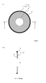
- FIG. 1 is a plan view and a cross-sectional view of a donut-type aperture stop 100A according to an embodiment of the present invention.
- FIG. 2 is a plan view and a cross-sectional view of the donut-type aperture stop 100B according to the embodiment of the present invention.
- 3A and 3B are a plan view and a cross-sectional view of the donut-type aperture stop 100C according to the embodiment of the present invention.
- FIG. 4 is a plan view and a cross-sectional view of a donut-type aperture stop 100D according to the embodiment of the present invention.
- FIG. 5 is a cross-sectional view of a lens system incorporating the donut-type aperture stop 100E according to the embodiment of the present invention.
- FIG. 6 is a plan view of a rotary aperture stop 150 in which a plurality of donut aperture stops 100A are combined.
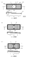
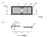
- 7A and 7B are a plan view and a cross-sectional view for explaining the operation of the two-blade aperture stop 200A according to the embodiment of the present invention.
- FIG. 8 is a plan view of a diaphragm blade member 20A constituting the two-blade aperture diaphragm 200A according to the embodiment of the present invention.
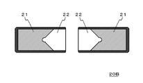
- FIG. 9 is a plan view of a diaphragm blade member 20B constituting the two-blade type aperture diaphragm according to the embodiment of the present invention.
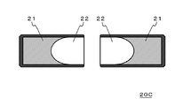
- FIG. 10 is a plan view of a diaphragm blade member 20C constituting the two-blade type aperture diaphragm according to the embodiment of the present invention.
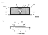
- FIG. 11 is a plan view and a cross-sectional view of the two-blade aperture stop 200B according to the embodiment of the present invention.
- 12A and 12B are a plan view and a cross-sectional view of the two-blade aperture stop 200C according to the embodiment of the present invention.
- FIG. 13 is a plan view and a cross-sectional view of a two-blade aperture stop 200D according to an embodiment of the present invention.
- FIG. 14 is a schematic configuration diagram of a light source device 300A according to the embodiment of the present invention.
- the donut-shaped aperture stop 100A includes a flat substrate 3 having an annular filter region 1 and a circular opening region 2 formed inside the filter region 1, and an outer portion fitted on the outer periphery of the flat substrate 3. It is formed from the frame 4. More specifically, the filter region 1 includes a filter layer 1 a provided in an annular shape on the surface of a transparent circular flat substrate 3, and the filter layer non-forming region at the center of the flat substrate 3 is open. Region 2 is set.
- the aperture stop 100A is configured for an illumination optical system, and the filter region 1 transmits light in the wavelength range of excitation light that causes the subject to emit fluorescence without substantially attenuating, and forms a subject image. This is a region that reduces or blocks light in the visible light region. If the wavelength range of the excitation light that causes the subject to emit fluorescence and the wavelength range of the visible light that forms the subject image overlap, the light in the wavelength range of the excitation light is transmitted without being substantially attenuated, and This is a region in which light other than the wavelength region of the excitation light in the visible light region that forms the subject image is reduced or blocked.
- the aperture region 2 is a region that transmits light in the wavelength region of excitation light that causes the subject to emit fluorescence and light in the visible light region (for example, wavelength 400 to 800 nm) that forms the subject image without being substantially attenuated. It is.
- the opening region 2 may be a total light transmission region that does not have a filter function for a specific wavelength region.
- the opening region 2 has a circular shape.
- the opening region 2 can take various shapes, and may be, for example, an ellipse or a rectangle.
- the light transmission characteristics of the filter region 1 can be appropriately determined according to the type of the subject to be observed, the photosensitive material, the optical contrast agent, the observation purpose, and the like.
- the accumulation site is used as an observation site, and fluorescence is emitted by irradiating ICG with excitation light, and the fluorescence is observed
- the peak of the excitation wavelength of ICG is 805 nm
- the peak of the fluorescence wavelength of ICG is 845 nm
- it is preferable to use 750 to 810 nm as an excitation wavelength region and white light including this excitation wavelength region as a light source. Therefore, in the filter region 1, light in the excitation wavelength region of 750 to 810 nm is transmitted, but light in the visible light region on the shorter wavelength side is reduced or blocked.
- the filter region 1 is formed in an annular shape on one surface of the flat substrate 3 and the entire other surface of the flat substrate 3 is longer than 810 nm.
- the fluorescent wavelength region cut filter layer 5 that blocks the light may be formed.
- HpD hematoporphyrin derivative
- tumor cells that have accumulated HpD emit fluorescence with peak wavelengths of 630 nm and 690 nm by excitation light having a peak wavelength of 405 nm. Therefore, it is preferable to set the wavelength range of excitation light to 385 to 425 nm, the wavelength range of fluorescence to be observed to 610 to 720 nm, and the light source to white light including the wavelength range of excitation light.
- the filter region 1 transmits light having a wavelength of 385 to 425 nm, which is the wavelength region of the excitation light, but it can block or reduce visible light on the shorter wavelength side and longer wavelength side than this wavelength region. It is preferable to block light on the shorter wavelength side and longer wavelength side than the wavelength range of the excitation light. Further, in accordance with the case of taking an observation image by the ICG described above, a fluorescence wavelength band cut filter is appropriately used when a donut aperture stop is used, or a fluorescence wavelength band cut filter layer is provided on the donut aperture stop. preferable.
- the ratio between the area (S1) of the filter region 1 and the area (S2) of the opening region 2 is such that the observation image by fluorescence from the observation site of the subject can be clearly observed without being buried in the subject image by the illumination light. Therefore, it is determined appropriately according to the intensity of the light source, the sensitivity of the imaging device, and the like.
- the filter layer 1a for forming the filter region 1 is formed on the flat substrate 3 so as to have the above-mentioned light transmission characteristics according to a general thin film forming method for optical filters such as vapor deposition and sputtering. Can do.
- the flat substrate 3 it is preferable to use a transparent parallel flat plate in the present embodiment, and it can be formed from, for example, blue plate glass, white plate glass, optical glass, an acrylic resin plate, or the like.
- the thickness of the flat substrate 3 can be appropriately determined according to the material of the flat substrate 3, the outer diameter of the filter region 1, and the like.
- the aperture stop of the present invention can take various forms.
- an annular substrate from which the opening region 2 is cut out may be used as the flat substrate 3 as in the aperture stop 100C shown in FIG.
- the filter region 1 is formed by using the flat base material 3 in which the color material is uniformly dispersed, and the flat base material 3 itself is cut away.
- the opening region 2 may be formed.
- the filter layer 1 a forming the filter region 1 is not limited to being formed on the flat substrate 3.
- the base material on which the filter layer 1a is formed may be a lens and formed on the surface thereof.
- An aperture stop 100E in FIG. 5 is obtained by forming a filter layer 1a in a ring shape on the surface of a condenser lens 3b that condenses light emitted from a light source 60 onto a light guide fiber 70 for an endoscope.
- the lens 3b forming the filter layer 1a is preferably a lens in the vicinity of a position where an aperture stop is installed in a lens system in a conventional light source device.
- FIG. 6 shows a rotation in which a plurality of aperture stops having the same area ratio between the filter region 1 and the opening region 2 are arranged around the rotation center 6o of the disc-shaped substrate 6 as in the above-described donut type aperture stop 100A.
- 3 is a plan view of a shaped aperture stop 150.
- FIG. According to this rotary aperture stop 150 by rotating the disk-shaped substrate 6 as shown by an arrow, the donut-type aperture stop 100A having the desired ratio of the filter region 1 and the aperture region 2 can be easily selected, and the subject can be selected. Can be illuminated.
- FIG. 7 is an explanatory view of a two-blade type aperture stop 200A which is an embodiment of the second aperture stop of the present invention.
- FIG. 8 is a pair of stop blades constituting the two-blade type aperture stop 200A. It is a top view of member 20A.
- the diaphragm blade member 20A has a filter part 21 in which a filter layer 21a is formed on the left and right sides of the surface of a rectangular flat substrate 23, and a non-filter part 22 that is a non-formation region of the filter layer 21a. It is fitted in.
- the filter layer 21a has a shape in which the non-filter part 22 side is recessed in a V shape. Similar to the filter layer 1a of the donut-shaped aperture stop 100A described above, the filter layer 21a transmits light in the wavelength region of excitation light that causes the subject to emit fluorescence without being substantially attenuated, and forms a subject image.
- the rectangular flat substrate 23 is formed of a transparent glass plate, an acrylic resin plate, or the like, similar to the aperture stop 100A described above.
- the two-blade type aperture stop 200A shown in FIG. 7 is constructed by combining a pair of stop blade members 20A so that both non-filter portions 21 overlap and movably mounted on a rail 25.
- the overlapping region of the non-filter portion 22 of the pair of aperture blade members 20A becomes the aperture region 2 of the two-blade aperture stop 200A, and excitation light that causes the subject to emit fluorescence. And light in the visible light region that forms the subject image.
- the pair of filter portions 21 surrounding the aperture region 2 become the filter region 1 of the two-blade type aperture stop 200A, which transmits the light in the wavelength region of the excitation light that causes the subject to emit fluorescence and transmits the subject image. The visible light that forms the light is reduced or blocked.
- the area of the opening region 2 is variable.
- FIG. 7A the state where the opening region 2 is maximized, and FIG.
- the area of the opening region 2 can be continuously changed between the state in which the opening region 2 is narrowed down and the state in which the opening region 2 is further narrowed down as shown in FIG. Therefore, it is possible to more appropriately adjust the balance of the light amount of the light that forms the subject image and the excitation light that forms the fluorescent image.
- a broken-line circle X around the aperture region 2 indicates the optical path diameter from the light source at the mounting position when the two-blade aperture stop 200A is mounted on an optical system such as a light source device. .
- the diameter of the filter area 1 is made larger than the optical path diameter from the light source at the mounting position of the two-blade type aperture stop 200A. It is preferable not to block the optical path. Thereby, the loss of the excitation light component contained in the light source can be reduced.
- the pair of diaphragm blade members 20A when combining the pair of diaphragm blade members 20A so that the two non-filter portions 22 overlap each other, the pair of diaphragm blade members 20A is as long as these opposed surfaces do not contact each other. It is desirable to place them as close as possible.
- a pair of diaphragm blade members 20A may be connected by a known connector so that the pair of diaphragm blade members 20A move symmetrically about the center p of the opening region 2.
- the drive source of the diaphragm blade member 20A may be manual or a stepping motor or the like.
- the aperture stop of the present invention can take various modes.
- the V-shaped opening angle ⁇ and the V-shaped depth d of the filter portion 21 are determined by the overlapping of the pair of non-filter portions 22. There is no particular limitation as long as it is formed.
- the filter portion 21 is recessed in a V shape on the non-filter portion 22 side.
- the filter portion 21 is recessed as long as the opening region 2 can be formed by overlapping the pair of non-filter portions 22.
- the opening region 2 is not particularly limited, and the opening region 2 is formed in a state in which the area of the opening region 2 is narrowed by denting the tip of the V-shaped recess in a semicircular shape like the diaphragm blade member 20B shown in FIG. May be circular.
- the planar shape itself of the flat substrate 23 forming the stop blade member 20D may be a shape having a dent similar to the filter portion 21, or FIG.
- the plate-like base material 23 itself has a light transmission characteristic similar to that of the filter layer 21a due to the uniform dispersion of the color material. You may form the opening area
- a fluorescence wavelength region cut filter layer 5 may be provided.
- the aperture stop of the present invention can take various modes.
- a filter region and an opening region located inside the filter region may be formed by combining three or more aperture blade members having a filter part and a non-filter part.
- the filter part is thermally expanded by heat from the light source and distortion occurs in the overlapping part of the filter parts.
- a two-blade type aperture stop is preferable to an aperture stop having three or more stop blade members.
- the aperture stop according to the present invention can be widely used in a light source device of various imaging devices that simultaneously capture a subject image by illumination light and a fluorescent image from an observation site of the subject. It is possible to prevent the fluorescent image from becoming weak.
- FIG. 14 is a schematic diagram of a configuration in which the two-blade aperture stop 200A of the present invention is incorporated in a light source device 300A of a known near-infrared fluorescent image capturing endoscope device using ICG.
- the endoscope apparatus to which the light source device 300A is attached takes a subject image by visible light using a living body as a subject, and simultaneously takes a fluorescent image in an infrared light band emitted by an ICG administered to a living tissue. It can be set as the structure similar to the endoscope apparatus as described in PCT / JP2009 / 67352.
- the light in the wavelength region corresponding to the fluorescence from the observation site of the subject is transmitted, and the transmission in the visible light region that forms the subject image is reduced or
- An endoscope apparatus having an aperture stop to be blocked in front of an image sensor such as a CCD is used.
- the ratio of the intensity of the fluorescent image to the subject image can be further improved with a simple configuration.
- the light source device 300A includes a white light source 60 such as a halogen lamp, a xenon lamp, and an LED, a concave mirror 61 provided behind the white light source 60, a fluorescent wavelength band cut filter 62 sequentially provided on the front surface of the white light source 60, 2 shown in FIG. It has a single blade type aperture stop 200A and a condenser lens 3b. Further, a total light quantity stop 63 for reducing the total light quantity of the illumination light can be provided between the two-blade aperture stop 200A and the condenser lens 3b as necessary.
- a white light source 60 such as a halogen lamp, a xenon lamp, and an LED
- a concave mirror 61 provided behind the white light source 60
- a fluorescent wavelength band cut filter 62 sequentially provided on the front surface of the white light source 60, 2 shown in FIG. It has a single blade type aperture stop 200A and a condenser lens 3b.
- illumination light having an appropriate ratio between the amount of excitation light and the amount of light in the visible light region is endoscope. It can be fed into the light guide fiber 70 of the device.
- the aperture stop of the present invention is useful in a fluorescent image pickup device using a fluorescent reagent such as ICG, a light source device of an image pickup device in a medical field such as PDD, PDT, etc., and also in a fluorescent image in an analysis test of food and various materials. It is also useful in a light source device for taking a picture.
Landscapes
- Health & Medical Sciences (AREA)
- Physics & Mathematics (AREA)
- Life Sciences & Earth Sciences (AREA)
- Surgery (AREA)
- Optics & Photonics (AREA)
- Engineering & Computer Science (AREA)
- General Physics & Mathematics (AREA)
- General Health & Medical Sciences (AREA)
- Nuclear Medicine, Radiotherapy & Molecular Imaging (AREA)
- Pathology (AREA)
- Biomedical Technology (AREA)
- Veterinary Medicine (AREA)
- Radiology & Medical Imaging (AREA)
- Public Health (AREA)
- Animal Behavior & Ethology (AREA)
- Medical Informatics (AREA)
- Molecular Biology (AREA)
- Heart & Thoracic Surgery (AREA)
- Biophysics (AREA)
- General Engineering & Computer Science (AREA)
- Analytical Chemistry (AREA)
- Chemical & Material Sciences (AREA)
- Biochemistry (AREA)
- Immunology (AREA)
- Spectroscopy & Molecular Physics (AREA)
- Astronomy & Astrophysics (AREA)
- Endoscopes (AREA)
- Diaphragms For Cameras (AREA)
- Instruments For Viewing The Inside Of Hollow Bodies (AREA)
- Investigating, Analyzing Materials By Fluorescence Or Luminescence (AREA)
Abstract
Description
1a フィルタ層
2 開口領域
3 平板状基材
3b コンデンサーレンズ
4 外枠
5 蛍光波長域カットフィルタ層
6 円盤形基板
20A、20B、20C、20D、20E、20F 絞り羽根部材
21 フィルタ部
21a フィルタ層
22 非フィルタ部
23 平板状基材
24 外枠
25 レール
50 励起光カットフィルタ
60 光源
61 凹面鏡
62 蛍光波長域カットフィルタ
63 全光量絞り
70 ライトガイドファイバー
100A、100B、100C、100D、100E ドーナツ型開口絞り
150 回転形開口絞り
200A、200B、200C、200D 2枚羽根型開口絞り
300A 光源装置
Claims (9)
- 可視光域の照明光の反射による被写体像と、被写体中の蛍光物質による蛍光像とを同時に観察する場合の光源装置に使用される照明用開口絞りであって、
基材に環状にフィルタ領域が形成され、該フィルタ領域の内側に開口領域が形成され、フィルタ領域が、被写体に蛍光を発光させる励起光の波長域の光を透過させ、かつ被写体像を形成する可視光域の光の透過を低減又は遮断する照明用開口絞り。 - 励起光が赤外光である請求項1記載の照明用開口絞り。
- 開口絞りの全面に、前記蛍光の波長域の光の透過を遮断するフィルタ層が設けられている請求項1又は2記載の照明用開口絞り。
- 可視光域の照明光の反射による被写体像と、被写体中の蛍光物質による蛍光像とを同時に観察する場合の光源装置に使用される照明用開口絞りであって、
一部又は全部にフィルタ部が形成された絞り羽根部材を複数備え、複数の絞り羽根部材のフィルタ部から形成されたフィルタ領域と該フィルタ領域の内側に位置する開口領域とを有し、フィルタ領域が、被写体に蛍光を発光させる励起光の波長域の光を透過させ、かつ被写体像を形成する可視光域の光の透過を低減又は遮断する照明用開口絞り。 - 開口領域の面積が可変である請求項4記載の照明用開口絞り。
- 励起光が赤外光である請求項4又は5記載の照明用開口絞り。
- フィルタ領域の径が、照明用開口絞りの取付位置における光源からの光路径よりも大きく、フィルタ領域が前記光路を遮らない請求項4~6記載の照明用開口絞り。
- 照明光による被写体像と、被写体の観察部位からの蛍光像とを同時に観察する撮像装置に使用される光源装置であって、白色光源と、請求項1~7のいずれかに記載の照明用開口絞りを備えた光源装置。
- 内視鏡装置に使用される請求項8記載の光源装置。
Priority Applications (5)
| Application Number | Priority Date | Filing Date | Title |
|---|---|---|---|
| KR1020137019247A KR20140001985A (ko) | 2011-01-20 | 2011-12-22 | 조명용 개구 조리개 |
| JP2012553585A JP5796244B2 (ja) | 2011-01-20 | 2011-12-22 | 照明用開口絞り |
| EP11856442.6A EP2666402B1 (en) | 2011-01-20 | 2011-12-22 | A light source device having an illumination aperture diaphragm |
| US13/980,625 US9175831B2 (en) | 2011-01-20 | 2011-12-22 | Illumination aperture diaphragm |
| CN201180065496.5A CN103327885B (zh) | 2011-01-20 | 2011-12-22 | 照明用孔径光阑 |
Applications Claiming Priority (2)
| Application Number | Priority Date | Filing Date | Title |
|---|---|---|---|
| JP2011-010056 | 2011-01-20 | ||
| JP2011010056 | 2011-01-20 |
Publications (1)
| Publication Number | Publication Date |
|---|---|
| WO2012098806A1 true WO2012098806A1 (ja) | 2012-07-26 |
Family
ID=46515443
Family Applications (1)
| Application Number | Title | Priority Date | Filing Date |
|---|---|---|---|
| PCT/JP2011/079901 Ceased WO2012098806A1 (ja) | 2011-01-20 | 2011-12-22 | 照明用開口絞り |
Country Status (6)
| Country | Link |
|---|---|
| US (1) | US9175831B2 (ja) |
| EP (1) | EP2666402B1 (ja) |
| JP (1) | JP5796244B2 (ja) |
| KR (1) | KR20140001985A (ja) |
| CN (1) | CN103327885B (ja) |
| WO (1) | WO2012098806A1 (ja) |
Cited By (7)
| Publication number | Priority date | Publication date | Assignee | Title |
|---|---|---|---|---|
| JP5884021B2 (ja) * | 2013-02-13 | 2016-03-15 | パナソニックIpマネジメント株式会社 | マルチスペクトル撮像装置およびマルチスペクトル撮像方法 |
| JP2018049261A (ja) * | 2016-08-17 | 2018-03-29 | ライカ インストゥルメンツ (シンガポール) プライヴェット リミテッドLeica Instruments (Singapore) Pte. Ltd. | マルチスペクトル絞り装置 |
| JP2019042195A (ja) * | 2017-09-04 | 2019-03-22 | 池上通信機株式会社 | 撮像装置 |
| JP2019113850A (ja) * | 2014-03-04 | 2019-07-11 | ノバダック テクノロジーズ ユーエルシー | 空間およびスペクトルフィルタリング開口およびそれを含む光学イメージングシステム |
| JP2019527077A (ja) * | 2016-05-30 | 2019-09-26 | ライカ インストゥルメンツ (シンガポール) プライヴェット リミテッドLeica Instruments (Singapore) Pte. Ltd. | 透過窓を有するフィルタシステムを使用して、部分的に蛍光性である対象物を観察するための医療装置 |
| US10656316B2 (en) | 2015-08-31 | 2020-05-19 | Novadaq Technologies ULC | Polarization dependent filter, system using the same, and associated kits and methods |
| US12004716B2 (en) | 2014-03-04 | 2024-06-11 | Stryker Corporation | Relay lens system for broadband imaging |
Families Citing this family (17)
| Publication number | Priority date | Publication date | Assignee | Title |
|---|---|---|---|---|
| WO2015137148A1 (ja) * | 2014-03-14 | 2015-09-17 | ソニー株式会社 | 撮像装置、アイリス装置、撮像方法、およびプログラム |
| JP6727800B2 (ja) | 2015-03-05 | 2020-07-22 | キヤノン株式会社 | 光量調節装置、レンズ鏡筒、および光学装置 |
| JP6442065B2 (ja) * | 2015-09-16 | 2018-12-19 | 富士フイルム株式会社 | フォーカス装置,撮像システムおよびフォーカス駆動信号出力方法 |
| EP4442222A3 (en) * | 2015-11-13 | 2024-12-18 | Stryker Corporation | Systems and methods for illumination and imaging of a target |
| CN106773018B (zh) * | 2015-11-23 | 2019-05-28 | 中国科学院大连化学物理研究所 | 一种红外可变孔径光阑 |
| CN105425505B (zh) * | 2015-12-10 | 2017-10-31 | 上海机电工程研究所 | 离轴折反式光学系统的可变光阑调节方法 |
| CN105678215A (zh) * | 2015-12-28 | 2016-06-15 | 北京天诚盛业科技有限公司 | 成像模组、成像装置和移动终端 |
| JP6671030B2 (ja) * | 2016-03-09 | 2020-03-25 | パナソニックIpマネジメント株式会社 | 照明装置 |
| US10386627B2 (en) * | 2017-01-20 | 2019-08-20 | Verily Life Sciences Llc | Simultaneous visible and fluorescence endoscopic imaging |
| EP3440989A1 (en) * | 2017-08-09 | 2019-02-13 | Koninklijke Philips N.V. | System for imaging an eye |
| CN109549614B (zh) * | 2017-09-27 | 2022-09-20 | 深圳市绎立锐光科技开发有限公司 | 内窥镜系统 |
| CN109348015B (zh) * | 2018-11-27 | 2020-09-25 | 维沃移动通信(杭州)有限公司 | 摄像模组、摄像模组的控制方法及移动终端 |
| CN109520987B (zh) * | 2018-12-19 | 2024-07-12 | 苏州汶颢微流控技术股份有限公司 | Atp荧光检测仪 |
| TWI745745B (zh) * | 2019-09-10 | 2021-11-11 | 光芒光學股份有限公司 | 取像鏡頭與遮光元件的製作方法 |
| US20220349750A1 (en) * | 2019-09-24 | 2022-11-03 | Agilent Technologies, Inc. | Variable transmission aperture |
| US11853845B2 (en) * | 2020-09-02 | 2023-12-26 | Cognex Corporation | Machine vision system and method with multi-aperture optics assembly |
| EP4732750A1 (en) * | 2023-09-26 | 2026-04-29 | Shenzhen Mindray Bio-Medical Electronics Co., Ltd. | Endoscope and diaphragm of endoscope |
Citations (8)
| Publication number | Priority date | Publication date | Assignee | Title |
|---|---|---|---|---|
| JPH10151104A (ja) * | 1996-11-25 | 1998-06-09 | Olympus Optical Co Ltd | 蛍光内視鏡装置 |
| JPH10201707A (ja) | 1996-11-20 | 1998-08-04 | Olympus Optical Co Ltd | 内視鏡装置 |
| JP2001078205A (ja) | 1999-09-01 | 2001-03-23 | Hamamatsu Photonics Kk | 微弱光カラー撮像装置 |
| JP2002369223A (ja) * | 2001-06-08 | 2002-12-20 | Pentax Corp | 画像検出装置と絞り装置 |
| JP2004205951A (ja) * | 2002-12-26 | 2004-07-22 | Canon Inc | 光量調整装置及びそれを用いた光学機器 |
| JP2004205557A (ja) * | 2002-12-20 | 2004-07-22 | Tamron Co Ltd | 光量調節装置 |
| JP2008188196A (ja) | 2007-02-05 | 2008-08-21 | Sanyo Electric Co Ltd | 撮像装置 |
| JP2008259591A (ja) | 2007-04-10 | 2008-10-30 | Hamamatsu Photonics Kk | 蛍光観察用光源装置及びそれを用いた蛍光観察装置 |
Family Cites Families (8)
| Publication number | Priority date | Publication date | Assignee | Title |
|---|---|---|---|---|
| US7179222B2 (en) | 1996-11-20 | 2007-02-20 | Olympus Corporation | Fluorescent endoscope system enabling simultaneous achievement of normal light observation based on reflected light and fluorescence observation based on light with wavelengths in infrared spectrum |
| US6293911B1 (en) * | 1996-11-20 | 2001-09-25 | Olympus Optical Co., Ltd. | Fluorescent endoscope system enabling simultaneous normal light observation and fluorescence observation in infrared spectrum |
| JP4931288B2 (ja) * | 2001-06-08 | 2012-05-16 | ペンタックスリコーイメージング株式会社 | 画像検出装置と絞り装置 |
| US7042662B2 (en) | 2002-12-26 | 2006-05-09 | Canon Kabushiki Kaisha | Light amount adjusting device, and optical device using the light amount adjusting device |
| JP4438056B2 (ja) * | 2003-06-26 | 2010-03-24 | キヤノン株式会社 | 光量調節部材の製造方法 |
| JP4744288B2 (ja) | 2005-12-21 | 2011-08-10 | オリンパスメディカルシステムズ株式会社 | 内視鏡装置 |
| JP2009067352A (ja) | 2007-09-18 | 2009-04-02 | Nippon Seiki Co Ltd | ヘッドアップディスプレイ装置 |
| WO2011007435A1 (ja) * | 2009-07-16 | 2011-01-20 | 株式会社山野光学 | 開口絞り |
-
2011
- 2011-12-22 EP EP11856442.6A patent/EP2666402B1/en active Active
- 2011-12-22 CN CN201180065496.5A patent/CN103327885B/zh not_active Expired - Fee Related
- 2011-12-22 JP JP2012553585A patent/JP5796244B2/ja active Active
- 2011-12-22 KR KR1020137019247A patent/KR20140001985A/ko not_active Withdrawn
- 2011-12-22 WO PCT/JP2011/079901 patent/WO2012098806A1/ja not_active Ceased
- 2011-12-22 US US13/980,625 patent/US9175831B2/en active Active
Patent Citations (8)
| Publication number | Priority date | Publication date | Assignee | Title |
|---|---|---|---|---|
| JPH10201707A (ja) | 1996-11-20 | 1998-08-04 | Olympus Optical Co Ltd | 内視鏡装置 |
| JPH10151104A (ja) * | 1996-11-25 | 1998-06-09 | Olympus Optical Co Ltd | 蛍光内視鏡装置 |
| JP2001078205A (ja) | 1999-09-01 | 2001-03-23 | Hamamatsu Photonics Kk | 微弱光カラー撮像装置 |
| JP2002369223A (ja) * | 2001-06-08 | 2002-12-20 | Pentax Corp | 画像検出装置と絞り装置 |
| JP2004205557A (ja) * | 2002-12-20 | 2004-07-22 | Tamron Co Ltd | 光量調節装置 |
| JP2004205951A (ja) * | 2002-12-26 | 2004-07-22 | Canon Inc | 光量調整装置及びそれを用いた光学機器 |
| JP2008188196A (ja) | 2007-02-05 | 2008-08-21 | Sanyo Electric Co Ltd | 撮像装置 |
| JP2008259591A (ja) | 2007-04-10 | 2008-10-30 | Hamamatsu Photonics Kk | 蛍光観察用光源装置及びそれを用いた蛍光観察装置 |
Non-Patent Citations (1)
| Title |
|---|
| See also references of EP2666402A4 |
Cited By (9)
| Publication number | Priority date | Publication date | Assignee | Title |
|---|---|---|---|---|
| JP5884021B2 (ja) * | 2013-02-13 | 2016-03-15 | パナソニックIpマネジメント株式会社 | マルチスペクトル撮像装置およびマルチスペクトル撮像方法 |
| US9843740B2 (en) | 2013-02-13 | 2017-12-12 | Panasonic Intellectual Property Management Co., Ltd. | Multispectral imaging device and multispectral imaging method |
| JP2019113850A (ja) * | 2014-03-04 | 2019-07-11 | ノバダック テクノロジーズ ユーエルシー | 空間およびスペクトルフィルタリング開口およびそれを含む光学イメージングシステム |
| US10948638B2 (en) | 2014-03-04 | 2021-03-16 | Stryker European Operations Limited | Spatial and spectral filtering apertures and optical imaging systems including the same |
| US12004716B2 (en) | 2014-03-04 | 2024-06-11 | Stryker Corporation | Relay lens system for broadband imaging |
| US10656316B2 (en) | 2015-08-31 | 2020-05-19 | Novadaq Technologies ULC | Polarization dependent filter, system using the same, and associated kits and methods |
| JP2019527077A (ja) * | 2016-05-30 | 2019-09-26 | ライカ インストゥルメンツ (シンガポール) プライヴェット リミテッドLeica Instruments (Singapore) Pte. Ltd. | 透過窓を有するフィルタシステムを使用して、部分的に蛍光性である対象物を観察するための医療装置 |
| JP2018049261A (ja) * | 2016-08-17 | 2018-03-29 | ライカ インストゥルメンツ (シンガポール) プライヴェット リミテッドLeica Instruments (Singapore) Pte. Ltd. | マルチスペクトル絞り装置 |
| JP2019042195A (ja) * | 2017-09-04 | 2019-03-22 | 池上通信機株式会社 | 撮像装置 |
Also Published As
| Publication number | Publication date |
|---|---|
| US9175831B2 (en) | 2015-11-03 |
| EP2666402A1 (en) | 2013-11-27 |
| CN103327885A (zh) | 2013-09-25 |
| JP5796244B2 (ja) | 2015-10-21 |
| JPWO2012098806A1 (ja) | 2014-06-09 |
| KR20140001985A (ko) | 2014-01-07 |
| US20130306880A1 (en) | 2013-11-21 |
| EP2666402B1 (en) | 2020-04-15 |
| CN103327885B (zh) | 2017-08-29 |
| EP2666402A4 (en) | 2015-11-25 |
Similar Documents
| Publication | Publication Date | Title |
|---|---|---|
| JP5796244B2 (ja) | 照明用開口絞り | |
| WO2011007435A1 (ja) | 開口絞り | |
| CN101744611B (zh) | 用于光动力治疗和摄影检测的装置 | |
| JP5945104B2 (ja) | 蛍光手術用実体顕微鏡 | |
| KR100798486B1 (ko) | 형광 진단 및 광역동치료를 위한 광원장치 | |
| CA2481112A1 (en) | Cancer detection and adaptive dose optimization treatment system | |
| WO2016160820A1 (en) | Method and apparatus for concurrent imaging at visible and infrared wavelengths | |
| CN108014424B (zh) | 一种内窥镜装置 | |
| JP2016120105A (ja) | 照明装置、照明方法及び観察装置 | |
| Leonhard | New incoherent autofluorescence/fluorescence system for early detection of lung cancer | |
| JP2016120104A (ja) | 照明装置、照明方法及び観察装置 | |
| JP5418707B2 (ja) | 開口絞り | |
| KR20190067337A (ko) | 광섬유기반 분광시스템과 결합된 파장가변 필터를 이용한 형광영상 시스템 | |
| JP5224078B2 (ja) | 開口絞り | |
| CN114366000B (zh) | 一种光源装置和内窥镜成像系统 | |
| JP6867533B1 (ja) | 光源装置 | |
| CN103837509A (zh) | 时差式荧光检测用光源装置、影像撷取系统及撷取方法 | |
| HK40049047A (zh) | 光源装置 | |
| CN120959656A (zh) | 光源模块、光源设备和内窥镜系统 |
Legal Events
| Date | Code | Title | Description |
|---|---|---|---|
| 121 | Ep: the epo has been informed by wipo that ep was designated in this application |
Ref document number: 11856442 Country of ref document: EP Kind code of ref document: A1 |
|
| WWE | Wipo information: entry into national phase |
Ref document number: 2012553585 Country of ref document: JP |
|
| ENP | Entry into the national phase |
Ref document number: 20137019247 Country of ref document: KR Kind code of ref document: A |
|
| WWE | Wipo information: entry into national phase |
Ref document number: 13980625 Country of ref document: US |
|
| NENP | Non-entry into the national phase |
Ref country code: DE |
|
| WWE | Wipo information: entry into national phase |
Ref document number: 2011856442 Country of ref document: EP |