WO2012100578A1 - 一种交流发电机及其发电方法 - Google Patents
一种交流发电机及其发电方法 Download PDFInfo
- Publication number
- WO2012100578A1 WO2012100578A1 PCT/CN2011/082187 CN2011082187W WO2012100578A1 WO 2012100578 A1 WO2012100578 A1 WO 2012100578A1 CN 2011082187 W CN2011082187 W CN 2011082187W WO 2012100578 A1 WO2012100578 A1 WO 2012100578A1
- Authority
- WO
- WIPO (PCT)
- Prior art keywords
- amplitude
- permanent magnet
- alternating current
- alternator
- equal
- Prior art date
- Legal status (The legal status is an assumption and is not a legal conclusion. Google has not performed a legal analysis and makes no representation as to the accuracy of the status listed.)
- Ceased
Links
Images


Classifications
-
- H—ELECTRICITY
- H02—GENERATION; CONVERSION OR DISTRIBUTION OF ELECTRIC POWER
- H02P—CONTROL OR REGULATION OF ELECTRIC MOTORS, ELECTRIC GENERATORS OR DYNAMO-ELECTRIC CONVERTERS; CONTROLLING TRANSFORMERS, REACTORS OR CHOKE COILS
- H02P9/00—Arrangements for controlling electric generators for the purpose of obtaining a desired output
- H02P9/42—Arrangements for controlling electric generators for the purpose of obtaining a desired output to obtain desired frequency without varying speed of the generator
-
- H—ELECTRICITY
- H02—GENERATION; CONVERSION OR DISTRIBUTION OF ELECTRIC POWER
- H02K—DYNAMO-ELECTRIC MACHINES
- H02K1/00—Details of the magnetic circuit
- H02K1/06—Details of the magnetic circuit characterised by the shape, form or construction
- H02K1/12—Stationary parts of the magnetic circuit
-
- H—ELECTRICITY
- H02—GENERATION; CONVERSION OR DISTRIBUTION OF ELECTRIC POWER
- H02K—DYNAMO-ELECTRIC MACHINES
- H02K1/00—Details of the magnetic circuit
- H02K1/06—Details of the magnetic circuit characterised by the shape, form or construction
- H02K1/22—Rotating parts of the magnetic circuit
- H02K1/27—Rotor cores with permanent magnets
-
- H—ELECTRICITY
- H02—GENERATION; CONVERSION OR DISTRIBUTION OF ELECTRIC POWER
- H02K—DYNAMO-ELECTRIC MACHINES
- H02K11/00—Structural association of dynamo-electric machines with electric components or with devices for shielding, monitoring or protection
- H02K11/04—Structural association of dynamo-electric machines with electric components or with devices for shielding, monitoring or protection for rectification
- H02K11/049—Rectifiers associated with stationary parts, e.g. stator cores
- H02K11/05—Rectifiers associated with casings, enclosures or brackets
-
- H—ELECTRICITY
- H02—GENERATION; CONVERSION OR DISTRIBUTION OF ELECTRIC POWER
- H02K—DYNAMO-ELECTRIC MACHINES
- H02K16/00—Machines with more than one rotor or stator
- H02K16/04—Machines with one rotor and two stators
-
- H—ELECTRICITY
- H02—GENERATION; CONVERSION OR DISTRIBUTION OF ELECTRIC POWER
- H02P—CONTROL OR REGULATION OF ELECTRIC MOTORS, ELECTRIC GENERATORS OR DYNAMO-ELECTRIC CONVERTERS; CONTROLLING TRANSFORMERS, REACTORS OR CHOKE COILS
- H02P5/00—Arrangements specially adapted for regulating or controlling the speed or torque of two or more electric motors
- H02P5/74—Arrangements specially adapted for regulating or controlling the speed or torque of two or more electric motors controlling two or more AC dynamo-electric motors
-
- H—ELECTRICITY
- H02—GENERATION; CONVERSION OR DISTRIBUTION OF ELECTRIC POWER
- H02P—CONTROL OR REGULATION OF ELECTRIC MOTORS, ELECTRIC GENERATORS OR DYNAMO-ELECTRIC CONVERTERS; CONTROLLING TRANSFORMERS, REACTORS OR CHOKE COILS
- H02P2207/00—Indexing scheme relating to controlling arrangements characterised by the type of motor
- H02P2207/05—Synchronous machines, e.g. with permanent magnets or DC excitation
Definitions
- the invention relates to a power generation method of an alternator and a generator thereof.
- Inverter generators have developed rapidly in the field of small engine generators in recent years due to their small size, light weight and good electrical performance.
- the working principle of the existing inverter generator is to use a multi-pole AC permanent magnet generator to send a higher frequency equal amplitude AC.
- the alternating current is rectified into a constant direct current by a controlled rectification method, and then converted into a required alternating current by an inverter circuit, commonly known as an ADA mode.
- the IGBT power transistor Since the existing ADA inverter circuit passes through the bridge circuit, the IGBT power transistor is used to chop the DC current, and then the waveform is shaped by the LC circuit to be reduced to an AC sine wave. Because the use of IGBT power transistors operating at a chopping frequency of 20K will produce The large switching loss causes the heat and power loss of the transistor, which reduces the efficiency. At the same time, the high-power inductor used to shape the post-chopper waveform also generates a large amount of heat, resulting in a large loss. At the same time, multiple harmonics of the 20K chopping frequency will generate high-frequency radio electromagnetic waves that can be emitted. If the generator power is to be made larger, the radio electromagnetic wave will be larger, which will not pass the existing European EMC certification requirements.
- the alternating current of the sinusoidal waveform is obtained by rectifying the higher frequency equal amplitude alternating current directly by the controllable rectification method and controlling the conduction angle at different times, but the waveform distortion is large, and The distortion changes more under different loads. Therefore, it is impossible to meet the requirements of many electrical appliances.
- the IGBT high-power transistor, large-capacity electrolytic capacitor, and high-power inductor used in the ADA inverter method are expensive, and the IGBT transistor specifications increase exponentially with the increase of current, so it is necessary to manufacture Generators with more than 5 kW or more will cost more. Therefore, it is still difficult to replace traditional generators with inverter generators.
- the object of the present invention is to provide a power generation method for an alternator, by which an alternator can generate a sine wave output voltage with a small waveform distortion and no high frequency radio electromagnetic wave interference.
- the alternator designed by the method not only has all the advantages of the existing inverter generator, but also has a manufacturing cost much lower than that of the existing inverter generator, and even lower than the manufacturing cost of the current general-purpose generator, and does not exist at the same time.
- High-frequency radio electromagnetic waves can pass the existing European EMC certification requirements.
- the technical solution of the present invention is: an electric power generation method of an alternator, in which two stator coils of a multi-pole permanent magnet generator capable of emitting equal-amplitude alternating current of different frequencies are connected in series, so that the two multi-pole permanent magnets generate electricity
- the equal frequency alternating currents emitted by the machine are superimposed to generate an amplitude modulated alternating current with an envelope whose amplitude varies with two equal amplitude alternating current voltage differences, and then the amplitude modulated alternating current is forward-reversed and rectified by a controllable rectifier circuit, and is filtered and formed.
- two multi-pole permanent magnet generators with different magnetic pole numbers can be coaxially mounted to emit equal-amplitude alternating currents of different frequencies.
- two multi-pole permanent magnet generators with different rotational speeds and the same number of poles can be used to emit equal-amplitude alternating currents of different frequencies.
- the controllable rectifier circuit is preferably a thyristor rectifier circuit, and the thyristor rectifier circuit is used for forward-reverse rectifier rectification of the amplitude modulation alternating current as a well-known technology in the industry, and the thyristor rectifier circuit is not specifically implemented in the invention. limited.
- the invention also provides an alternator made according to the above method, which comprises two multi-pole permanent magnet generators capable of emitting equal-amplitude alternating current of different frequencies, a controllable rectifying circuit and a shaping filter circuit, the two The stator coils of the multi-pole permanent magnet generator are connected in series, and are sequentially connected to the controllable rectifier circuit and the shaping filter circuit.
- An advantage of the present invention is that the method of the present invention allows the alternator to produce a sinusoidal output voltage with a small waveform distortion and no high frequency radio electromagnetic interference.
- the alternator manufactured by the method not only has all the advantages of the existing inverter generator, but the manufacturing cost is much lower than that of the existing inverter generator, and even lower than the manufacturing cost of the current general-purpose generator, and There are no high-frequency radio electromagnetic waves and can pass the existing European EMC certification requirements.
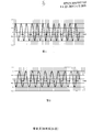
- Figure 1 is a high-frequency sinusoidal waveform diagram of the output alternating current of the main multi-pole permanent magnet generator
- FIG. 2 is a high-frequency sinusoidal waveform diagram of a secondary multi-pole permanent magnet generator outputting alternating current
- Fig. 3 is a voltage waveform diagram formed by superimposing the output alternating current of the main and auxiliary multi-pole permanent magnet generators
- Fig. 4 is a diagram showing voltage waveforms generated after forward-reverse rectification of a voltage waveform generated by superposition.
- FIG. 5 is a waveform diagram of a sine wave generated by shaping and filtering a voltage waveform after forward and reverse rectification processing
- Fig. 6 is a schematic view showing the circuit connection structure of the alternator of the present invention.
- Embodiment 1 The present invention provides a power generation method for an alternator, which firstly needs to prepare two primary and secondary permanent magnet multi-pole generators, and the two permanent magnet multi-pole generators can emit equal amplitudes at different frequencies.
- AC power the main and auxiliary permanent magnet multi-pole generators are all 10 pairs of SN monopole magnetic tiles, corresponding to the permanent magnet multi-pole generator of the 30-pole three-phase stator coil, but the rotation shafts of the two generators are independent of each other and the rotation speed Different, the secondary permanent magnet multi-pole generator has a lower speed than the main permanent magnet multi-pole generator.
- FIG. 1 the high-frequency sinusoidal waveform diagram of the alternating current multi-pole generator output AC
- FIG. 1 the high-frequency sinusoidal waveform diagram of the alternating current multi-pole generator output AC, and FIG.
- FIG. 2 is the high-frequency sinusoidal waveform diagram of the secondary permanent magnet multi-pole generator output alternating current, the cycle number ratio of the main The number of cycles of the permanent magnet generator is two waves.
- the stator coils of the two permanent magnet multi-pole generators are connected in series such that equal amplitude alternating currents of two different frequencies are superimposed to generate an amplitude modulated alternating current having an envelope with an amplitude varying with two equal amplitude alternating current voltage differences, the alternating current
- the voltage waveform is as shown in FIG. 3, and then the forward-controlled rectification of the amplitude-modulated alternating current obtained by the thyristor rectifier circuit is performed to form an alternating current output having an envelope frequency (the envelope of the alternating voltage waveform is the desired frequency).
- Sine wave as shown in Figure 4; finally, the waveform is shaped and filtered to obtain the sine wave AC of the desired frequency, as shown in Figure 5.
- FIG. 6 shows an alternator designed according to the above method.
- the alternator connects the stator coils of two permanent magnet multi-pole generators in series, and then sequentially connects with the controllable rectifier circuit and the shaping filter circuit, wherein
- the controllable rectifier circuit is a thyristor rectifier circuit.
- Embodiment 2 Compared with Embodiment 1, the main permanent magnet multi-pole generator in this embodiment is a 12-pair SN monopole magnetic tile, and a permanent magnet multi-pole generator corresponding to a 36-pole three-phase stator coil, and a secondary permanent magnet
- the multi-pole generator is a 10-pair SN monopole magnetic tile, which corresponds to a permanent magnet multi-pole generator of a 30-pole three-phase stator coil; the two generators are connected on the same rotating shaft at the same speed. Still shown in Fig.
- FIG. 1 the high-frequency sinusoidal waveform diagram of the alternating current multi-pole generator output AC
- Figure 2 shows the high-frequency sinusoidal waveform diagram of the secondary permanent magnet multi-pole generator output alternating current
- the cycle number ratio of the main The number of cycles of the permanent magnet generator is two waves.
- the stator coils of the two permanent magnet multi-pole generators are connected in series such that equal amplitude alternating currents of two different frequencies are superimposed to generate an amplitude modulated alternating current having an envelope with an amplitude varying with two equal amplitude alternating current voltage differences, the alternating current
- the voltage waveform is as shown in FIG.
- the forward-controlled rectification of the amplitude-modulated alternating current obtained by the thyristor rectifier circuit is performed to form an alternating current output having an envelope frequency (the envelope of the alternating voltage waveform is the desired frequency).
- Sine wave as shown in Figure 4; finally, the waveform is shaped and filtered to obtain the sine wave AC of the desired frequency, as shown in Figure 5.
- the method of the present invention can cause the alternator to generate a sine wave output voltage with a small waveform distortion and no high frequency radio electromagnetic wave interference.
- the alternator manufactured by the method not only has all the advantages of the existing inverter generator, but the manufacturing cost is greatly low.
Landscapes
- Engineering & Computer Science (AREA)
- Power Engineering (AREA)
- Control Of Eletrric Generators (AREA)
Description
本发明涉及一种交流发电机的发电方法及其发电机。
背景技术
逆变发电机由于其体积小,重量轻,电性能好等诸多优点,近年来在小型引擎发电机领域发展很快。现有的逆变发电机的工作原理是采用一个多极的交流永磁发电机发出一个频率较高的等幅交流电
,通过可控整流方法将该交流电整流成一个恒定的直流电,再通过逆变电路将其转换成所需要的交流电,俗称ADA方式。
由于现有的ADA逆变电路是通过桥式电路,采用IGBT功率晶体管对直流电斩波,再通过LC电路对该波形进行整形,还原成交流正弦波。因为采用IGBT功率晶体管在斩波频率20K的状态下工作会产生较
大的开关损耗,造成晶体管的发热及功率的损失,降低了效率,同时用来对斩波后波形进行整形的大功率电感也会产生较大的热量,造成较大的损耗。同时20K斩波频率的多次谐波会产生可发射的高频无线电电磁波,如要将发电机功率做的更大,则无线电电磁波也更大,这将无法通过现有的欧洲EMC认证要求。
当然现有技术中亦有通过对较高频率等幅交流电直接用可控整流方法整流,同时控制其不同时间的导通角来获得接近正弦波波形的交流电,但波形失真度较大,而且在不同负载下失真度变化更大,
从而无法满足许多用电器的要求。
从成本角度ADA逆变方式所使用的IGBT大功率晶体管,大容量电解电容,大功率电感的价格都较高,且IGBT晶体管规格随着电流的增大,价格成指数倍的增加,所以要制造5千瓦以上或更大功率的发电机成本将更高。所以目前逆变发电机还很难替代传统发电机。
发明内容
本发明目的是:提供一种交流发电机的发电方法,通过该方法可使交流发电机产生出波形失真度小,且不存在高频无线电电磁波干扰的正弦波输出电压。藉由该方法设计出的交流发电机不仅具有现有逆变发电机的所有优点,而且制造成本大大低于现有逆变发电机,甚至低于目前一般通用发电机的制造成本,同时不存在高频无线电电磁波,能够通过现有的欧洲EMC认证要求。
本发明的技术方案是:一种交流发电机的发电方法,将两个可发出不同频率等幅交流电的多极永磁发电机的定子线圈以串联方式连接,使得这两个多极永磁发电机发出的不同频率等幅交流电叠加产生一个幅度随两个等幅交流电电压差变化的具有包络线的调幅交流电,再将所述调幅交流电通过一个可控整流电路正反相整流,并滤波形成具有包络线频率的交流电输出。
本发明方法中,其中一个多极永磁发电机与另一个多极永磁电机的周波数差为两周时即产生两个周期变化的调幅叠加波形,所述两个周期变化的调幅叠加波形通过正反相整流并整形产生出一个完整的正弦波波形。
本发明方法中,可采用两个磁极数不同的多极永磁发电机同轴安装发出不同频率的等幅交流电。当然本发明方法中,也可采用两个转速不同而极数相同的多极永磁发电机发出不同频率的等幅交流电
。
本发明方法中,所述可控整流电路优选可控硅整流电路,所述采用可控硅整流电路对调幅交流电进行正反相整流为行业公知技术,本发明中不对可控硅整流电路作具体限定。
本发明同时提供一种根据上述方法制成的交流发电机,其包括两个可发出不同频率等幅交流电的多极永磁发电机和一个可控整流电路和一个整形滤波电路,所述两个多极永磁发电机的定子线圈以串联方式连接,再与可控整流电路和整形滤波电路顺序相连接。
本发明的优点是:本发明方法可使交流发电机产生出波形失真度小,且不存在高频无线电电磁波干扰的正弦波输出电压。藉由该方法制造出的交流发电机,其不但具有现有逆变发电机的所有优点,但制造成本大大低于现有逆变发电机,甚至低于目前一般通用发电机的制造成本,且不存在高频无线电电磁波,能够通过现有的欧洲EMC认证要求。
附图说明
下面结合附图及实施例对本发明作进一步描述:
图1为主多极永磁发电机输出交流电的高频正弦波形图;
图2为副多极永磁发电机输出交流电的高频正弦波形图;
图3为主、副多极永磁发电机输出交流电叠加后形成的电压波形图;
图4为对叠加产生的电压波形进行正反向整流处理后产生的电压波形图。
图5为对经正反向整流处理后的电压波形进行整形滤波后产生的正弦波波形图;
图6为本发明交流发电机的电路连接结构示意图。
具体实施方式
实施例1:本发明提供了一种交流发电机的发电方法,该方法首先需要准备主、副两个永磁多极发电机,这两个永磁多极发电机可发出不同频率的等幅交流电。本实施例中主、副永磁多极发电机均为10对S-N单极磁瓦,对应30极三相定子线圈的永磁多极发电机,但两个发电机的转轴相互独立、且转速不同,其中副永磁多极发电机的转速低于主永磁多极发电机。具体如图1所示,为主永磁多极发电机输出交流电的高频正弦波形图,而图2所示为副永磁多极发电机输出交流电的高频正弦波形图,其周波数比主永磁发电机周波数多两个波。将上述两个永磁多极发电机的定子线圈串联连接,使得两个不同频率的等幅交流电相叠加产生一个幅度随两个等幅交流电电压差变化的具有包络线的调幅交流电,该交流电压波形如图3所示,再通过可控硅整流电路对上述得到的调幅交流电进行正反相整流,形成具有包络线频率的交流电输出(该交流电压波形的包络线就是所需频率的正弦波),如图4所示;最后再对波形进行整形滤波得到所需频率的正弦波交流电,如图5所示。
如图6所示为依据上述方法设计的交流发电机,该交流发电机将两个永磁多极发电机的定子线圈串联连接,再与可控整流电路和整形滤波电路顺序相连接,其中的可控整流电路为可控硅整流电路。
实施例2:同实施例1相比,本实施例中主永磁多极发电机为12对S-N单极磁瓦,对应36极三相定子线圈的永磁多极发电机,而副永磁多极发电机为10对S-N单极磁瓦,对应30极三相定子线圈的永磁多极发电机;两个发电机连接在同一根转轴上,转速相同。依旧如图1所示,为主永磁多极发电机输出交流电的高频正弦波形图,而图2所示为副永磁多极发电机输出交流电的高频正弦波形图,其周波数比主永磁发电机周波数多两个波。将上述两个永磁多极发电机的定子线圈串联连接,使得两个不同频率的等幅交流电相叠加产生一个幅度随两个等幅交流电电压差变化的具有包络线的调幅交流电,该交流电压波形如图3所示,再通过可控硅整流电路对上述得到的调幅交流电进行正反相整流,形成具有包络线频率的交流电输出(该交流电压波形的包络线就是所需频率的正弦波),如图4所示;最后再对波形进行整形滤波得到所需频率的正弦波交流电,如图5所示。
本发明方法可使交流发电机产生出波形失真度小,且不存在高频无线电电磁波干扰的正弦波输出电压。藉由该方法制造出的交流发电机,其不但具有现有逆变发电机的所有优点,但制造成本大大低
于现有逆变发电机,甚至低于目前一般通用发电机的制造成本,且不存在高频无线电电磁波,能够通过现有的欧洲EMC认证要求。
Claims (6)
1.
一种交流发电机的发电方法,其特征在于将两个可发出不同频率等幅交流电的多极永磁发电机的定子线圈以串联方式连接,使得这两个多极永磁发电机发出的不同频率等幅交流电叠加产生一个幅度随两个等幅交流电电压差变化的具有包络线的调幅交流电,再将所述调幅交流电通过一个可控整流电路正反相整流,并滤波形成具有包络线频率的交流电输出。
2.
根据权利要求1所述的一种交流发电机的发电方法,其特征在于其中一个多极永磁发电机与另一个多极永磁发电机的周波数差为两周时,即产生两个周期变化的调幅叠加波形,所述两个周期变化的调幅叠加波形通过正反相整流并整形产生出一个完整的正弦波波形。
3.
根据权利要求1或2所述的一种交流发电机的发电方法,其特征在于采用两个磁极数不同而同轴安装的多极永磁发电机发出不同频率的等幅交流电。
4.
根据权利要求1或2所述的一种交流发电机的发电方法,其特征在于采用两个转速不同而极数相等的多极永磁发电机发出不同频率的等幅交流电。
5.
根据权利要求1或2所述的一种交流发电机的发电方法,其特征在于所述可控整流电路为可控硅整流电路。
6.
一种根据权利要求1-5中任意一项所述方法制成的交流发电机,其特征在于包括两个可发出不同频率等幅交流电的多极永磁发电机和一个可控整流电路和一个整形滤波电路,所述两个多极永磁发电机的定子线圈以串联方式连接,再与可控整流电路和整形滤波电路顺序相连接。
Priority Applications (2)
| Application Number | Priority Date | Filing Date | Title |
|---|---|---|---|
| EP11856961.5A EP2670014A4 (en) | 2011-01-30 | 2011-11-15 | Alternator and electricity generation method thereof |
| US13/982,597 US10284126B2 (en) | 2011-01-30 | 2011-11-15 | Method of generating electricity by an alternator and a generator using the same |
Applications Claiming Priority (2)
| Application Number | Priority Date | Filing Date | Title |
|---|---|---|---|
| CN2011100331744A CN102097894B (zh) | 2011-01-30 | 2011-01-30 | 一种交流发电机的发电方法及其发电机 |
| CN201110033174.4 | 2011-01-30 |
Publications (1)
| Publication Number | Publication Date |
|---|---|
| WO2012100578A1 true WO2012100578A1 (zh) | 2012-08-02 |
Family
ID=44130802
Family Applications (1)
| Application Number | Title | Priority Date | Filing Date |
|---|---|---|---|
| PCT/CN2011/082187 Ceased WO2012100578A1 (zh) | 2011-01-30 | 2011-11-15 | 一种交流发电机及其发电方法 |
Country Status (4)
| Country | Link |
|---|---|
| US (1) | US10284126B2 (zh) |
| EP (1) | EP2670014A4 (zh) |
| CN (1) | CN102097894B (zh) |
| WO (1) | WO2012100578A1 (zh) |
Cited By (1)
| Publication number | Priority date | Publication date | Assignee | Title |
|---|---|---|---|---|
| RU2636053C2 (ru) * | 2015-08-04 | 2017-11-20 | Российская Федерация, От Имени Которой Выступает Министерство Промышленности И Торговли Российской Федерации | Способ генерации переменных напряжений двух различных частот в турбогенераторе трехфазного тока |
Families Citing this family (3)
| Publication number | Priority date | Publication date | Assignee | Title |
|---|---|---|---|---|
| CN102097894B (zh) * | 2011-01-30 | 2012-07-25 | 陈维加 | 一种交流发电机的发电方法及其发电机 |
| CN102624310A (zh) * | 2012-03-19 | 2012-08-01 | 陈维加 | 一种交流发电机 |
| CN107986145A (zh) * | 2017-12-29 | 2018-05-04 | 苏州江南嘉捷机电技术研究院有限公司 | 一种电梯门机控制器封星装置 |
Citations (5)
| Publication number | Priority date | Publication date | Assignee | Title |
|---|---|---|---|---|
| US4684813A (en) * | 1985-01-03 | 1987-08-04 | Watson William K | Heterodyne system for electric power generation |
| RU2069033C1 (ru) * | 1989-06-12 | 1996-11-10 | Научно-Исследовательский Институт Автоматики И Электромеханики При Томском Институте Автоматизированных Систем Управления И Радиоэлектроники | Частотно-регулируемый электропривод |
| CN101111405A (zh) * | 2004-11-30 | 2008-01-23 | 丰田自动车株式会社 | 交流电压产生设备和动力输出设备 |
| CN102097894A (zh) * | 2011-01-30 | 2011-06-15 | 陈维加 | 一种交流发电机的发电方法及其发电机 |
| CN202034860U (zh) * | 2011-01-30 | 2011-11-09 | 陈维加 | 一种交流发电机 |
Family Cites Families (31)
| Publication number | Priority date | Publication date | Assignee | Title |
|---|---|---|---|---|
| US372934A (en) * | 1887-11-08 | Method of and apparatus for connecting alternate-current generators | ||
| US2437275A (en) * | 1946-07-27 | 1948-03-09 | Sperry Corp | Scanning reference generator |
| US2878397A (en) * | 1955-11-08 | 1959-03-17 | Bailey Meter Co | Multiple program control apparatus |
| US3237034A (en) * | 1956-11-08 | 1966-02-22 | Krasnow Shelley | Multi-voltage high frequency generator |
| US3173076A (en) * | 1960-07-07 | 1965-03-09 | Curtiss Wright Corp | High speed generator |
| US3134038A (en) * | 1962-06-04 | 1964-05-19 | Syncro Corp | Combined inductance-capacitance unit for permanent magnet alternator |
| US4045718A (en) * | 1975-04-02 | 1977-08-30 | Maremont Corporation | Multiple winding multiple voltage alternator electrical supply system |
| US4382188A (en) * | 1981-02-17 | 1983-05-03 | Lockheed Corporation | Dual-range drive configurations for synchronous and induction generators |
| US4694187A (en) * | 1986-01-13 | 1987-09-15 | Westinghouse Electric Corp. | Electromechanical constant speed drive generating system |
| US4908565A (en) * | 1987-02-18 | 1990-03-13 | Sundstrand Corporation | Power generating system |
| US4777376A (en) * | 1987-12-18 | 1988-10-11 | Sundstrand Corporation | Lightweight starting system for an electrically compensated constant speed drive |
| US4868406A (en) * | 1988-07-05 | 1989-09-19 | Sundstrand Corporation | Electrically compensated constant speed drive with prime mover start capability |
| US5023537A (en) * | 1989-08-23 | 1991-06-11 | Sundstrand Corporation | Low frequency feeder fault protection |
| US5258697A (en) * | 1991-10-23 | 1993-11-02 | Varelux Motor Corp. | Efficient permanent magnet electric motor |
| US6236123B1 (en) * | 1996-12-10 | 2001-05-22 | Active Power, Inc. | Generator providing alternating current which has a selected frequency |
| US6700242B2 (en) * | 2000-12-28 | 2004-03-02 | Hideo Kawamura | Magnetic flux controls for permanent-magnet motor-generator |
| US6541943B1 (en) * | 2001-03-02 | 2003-04-01 | Penntex Industries, Inc. | Regulator for boosting the output of an alternator |
| US7262539B2 (en) * | 2004-11-26 | 2007-08-28 | Pratt & Whitney Canada Corp. | Saturation control of electric machine |
| US7391126B2 (en) * | 2006-06-30 | 2008-06-24 | General Electric Company | Systems and methods for an integrated electrical sub-system powered by wind energy |
| US7710081B2 (en) * | 2006-10-27 | 2010-05-04 | Direct Drive Systems, Inc. | Electromechanical energy conversion systems |
| CN201138776Y (zh) * | 2008-01-07 | 2008-10-22 | 王光顺 | 调速恒频发电机 |
| US7573144B1 (en) * | 2008-02-07 | 2009-08-11 | Direct Drive Systems, Inc. | Reconfigurable power system using multiple phase-set electric machines |
| CN101610061B (zh) * | 2009-07-24 | 2012-09-12 | 陈维加 | 变频发电机 |
| CN201490959U (zh) * | 2009-07-24 | 2010-05-26 | 陈维加 | 变频发电机 |
| CN101672219A (zh) * | 2009-10-21 | 2010-03-17 | 陈维加 | 变频发电机组 |
| US20130181688A1 (en) * | 2010-10-06 | 2013-07-18 | Raven Energy Alternatives, Llc | System and method for variable speed generation of controlled high-voltage dc power |
| US8648559B2 (en) * | 2011-03-16 | 2014-02-11 | Deere & Company | System for controlling rotary electric machines to reduce current ripple on a direct current bus |
| US9154067B2 (en) * | 2013-12-19 | 2015-10-06 | Kohler Co. | Torque sharing on paralleled generators |
| US10483891B2 (en) * | 2017-01-06 | 2019-11-19 | Hamilton Sundstrand Corporation | Double stator permanent magnet machine with magnetic flux regulation |
| US20180262091A1 (en) * | 2017-03-13 | 2018-09-13 | Hamilton Sundstrand Corporation | Permanent magnet starter-generator with magnetic flux regulation |
| US10594179B2 (en) * | 2017-05-15 | 2020-03-17 | Wisconsin Alumni Research Foundation | Alternating flux barrier air gap in a spoke type machine |
-
2011
- 2011-01-30 CN CN2011100331744A patent/CN102097894B/zh not_active Expired - Fee Related
- 2011-11-15 EP EP11856961.5A patent/EP2670014A4/en not_active Withdrawn
- 2011-11-15 US US13/982,597 patent/US10284126B2/en not_active Expired - Fee Related
- 2011-11-15 WO PCT/CN2011/082187 patent/WO2012100578A1/zh not_active Ceased
Patent Citations (5)
| Publication number | Priority date | Publication date | Assignee | Title |
|---|---|---|---|---|
| US4684813A (en) * | 1985-01-03 | 1987-08-04 | Watson William K | Heterodyne system for electric power generation |
| RU2069033C1 (ru) * | 1989-06-12 | 1996-11-10 | Научно-Исследовательский Институт Автоматики И Электромеханики При Томском Институте Автоматизированных Систем Управления И Радиоэлектроники | Частотно-регулируемый электропривод |
| CN101111405A (zh) * | 2004-11-30 | 2008-01-23 | 丰田自动车株式会社 | 交流电压产生设备和动力输出设备 |
| CN102097894A (zh) * | 2011-01-30 | 2011-06-15 | 陈维加 | 一种交流发电机的发电方法及其发电机 |
| CN202034860U (zh) * | 2011-01-30 | 2011-11-09 | 陈维加 | 一种交流发电机 |
Non-Patent Citations (1)
| Title |
|---|
| See also references of EP2670014A4 * |
Cited By (1)
| Publication number | Priority date | Publication date | Assignee | Title |
|---|---|---|---|---|
| RU2636053C2 (ru) * | 2015-08-04 | 2017-11-20 | Российская Федерация, От Имени Которой Выступает Министерство Промышленности И Торговли Российской Федерации | Способ генерации переменных напряжений двух различных частот в турбогенераторе трехфазного тока |
Also Published As
| Publication number | Publication date |
|---|---|
| US20160336889A1 (en) | 2016-11-17 |
| EP2670014A4 (en) | 2017-10-18 |
| CN102097894B (zh) | 2012-07-25 |
| US10284126B2 (en) | 2019-05-07 |
| EP2670014A1 (en) | 2013-12-04 |
| CN102097894A (zh) | 2011-06-15 |
Similar Documents
| Publication | Publication Date | Title |
|---|---|---|
| CN105576921B (zh) | 可动态重构的电机、电机系统及电机动态重构方法 | |
| CN101291068B (zh) | 一种发电功率全控并网式风力发电驱动系统 | |
| JP6008473B2 (ja) | 発電機およびその製造方法 | |
| US11146199B2 (en) | Multi-phase motor system and control method | |
| CN102185399B (zh) | 多极电励磁变频发电机 | |
| JP5353522B2 (ja) | 電力変換装置 | |
| CN202503405U (zh) | 一种交流发电机 | |
| CN107171522B (zh) | 永磁电机、压缩机和制冷系统 | |
| CN1835351A (zh) | 可旋转电力电子变换器同步电机励磁装置 | |
| CN102097894B (zh) | 一种交流发电机的发电方法及其发电机 | |
| CN104333191B (zh) | 一种永磁电机、风力发电机系统及其控制方法 | |
| CN202034860U (zh) | 一种交流发电机 | |
| WO2014029199A1 (zh) | 一种交流发电机 | |
| WO2013139060A1 (zh) | 一种交流发电机 | |
| CN101719729B (zh) | 发电机的串联连接装置 | |
| CN202759356U (zh) | 一种交流发电机 | |
| CN201742195U (zh) | 多极永磁逆变发电电焊机组 | |
| CN203313024U (zh) | 增磁升压内滤波电励磁双凸极直流发电机 | |
| CN211744158U (zh) | 一种双凸极交流发电机 | |
| Zhao et al. | Co-Simulation of 600KW Traction Induction Motor Fed by PWM Inverter | |
| JP5300427B2 (ja) | 分散電源用発電装置の整流回路 | |
| Nedjar et al. | Parallel hybrid excitation synchronous machine optimization for railway application | |
| CN202930960U (zh) | 微功耗永磁风力发电机 | |
| CN214674942U (zh) | 一种高频直驱式正弦波逆变器 | |
| CN211151781U (zh) | 一种内定子励磁的宽调速范围同步电动机 |
Legal Events
| Date | Code | Title | Description |
|---|---|---|---|
| 121 | Ep: the epo has been informed by wipo that ep was designated in this application |
Ref document number: 11856961 Country of ref document: EP Kind code of ref document: A1 |
|
| REEP | Request for entry into the european phase |
Ref document number: 2011856961 Country of ref document: EP |
|
| WWE | Wipo information: entry into national phase |
Ref document number: 2011856961 Country of ref document: EP |
|
| NENP | Non-entry into the national phase |
Ref country code: DE |
|
| WWE | Wipo information: entry into national phase |
Ref document number: 13982597 Country of ref document: US |