WO2012101667A1 - 蓄電システム - Google Patents
蓄電システム Download PDFInfo
- Publication number
- WO2012101667A1 WO2012101667A1 PCT/JP2011/000351 JP2011000351W WO2012101667A1 WO 2012101667 A1 WO2012101667 A1 WO 2012101667A1 JP 2011000351 W JP2011000351 W JP 2011000351W WO 2012101667 A1 WO2012101667 A1 WO 2012101667A1
- Authority
- WO
- WIPO (PCT)
- Prior art keywords
- power storage
- storage device
- temperature
- temperature distribution
- assembled battery
- Prior art date
- Legal status (The legal status is an assumption and is not a legal conclusion. Google has not performed a legal analysis and makes no representation as to the accuracy of the status listed.)
- Ceased
Links
Images




Classifications
-
- H—ELECTRICITY
- H01—ELECTRIC ELEMENTS
- H01M—PROCESSES OR MEANS, e.g. BATTERIES, FOR THE DIRECT CONVERSION OF CHEMICAL ENERGY INTO ELECTRICAL ENERGY
- H01M10/00—Secondary cells; Manufacture thereof
- H01M10/60—Heating or cooling; Temperature control
- H01M10/63—Control systems
- H01M10/635—Control systems based on ambient temperature
-
- B—PERFORMING OPERATIONS; TRANSPORTING
- B60—VEHICLES IN GENERAL
- B60L—PROPULSION OF ELECTRICALLY-PROPELLED VEHICLES; SUPPLYING ELECTRIC POWER FOR AUXILIARY EQUIPMENT OF ELECTRICALLY-PROPELLED VEHICLES; ELECTRODYNAMIC BRAKE SYSTEMS FOR VEHICLES IN GENERAL; MAGNETIC SUSPENSION OR LEVITATION FOR VEHICLES; MONITORING OPERATING VARIABLES OF ELECTRICALLY-PROPELLED VEHICLES; ELECTRIC SAFETY DEVICES FOR ELECTRICALLY-PROPELLED VEHICLES
- B60L58/00—Methods or circuit arrangements for monitoring or controlling batteries or fuel cells, specially adapted for electric vehicles
- B60L58/10—Methods or circuit arrangements for monitoring or controlling batteries or fuel cells, specially adapted for electric vehicles for monitoring or controlling batteries
-
- B—PERFORMING OPERATIONS; TRANSPORTING
- B60—VEHICLES IN GENERAL
- B60L—PROPULSION OF ELECTRICALLY-PROPELLED VEHICLES; SUPPLYING ELECTRIC POWER FOR AUXILIARY EQUIPMENT OF ELECTRICALLY-PROPELLED VEHICLES; ELECTRODYNAMIC BRAKE SYSTEMS FOR VEHICLES IN GENERAL; MAGNETIC SUSPENSION OR LEVITATION FOR VEHICLES; MONITORING OPERATING VARIABLES OF ELECTRICALLY-PROPELLED VEHICLES; ELECTRIC SAFETY DEVICES FOR ELECTRICALLY-PROPELLED VEHICLES
- B60L58/00—Methods or circuit arrangements for monitoring or controlling batteries or fuel cells, specially adapted for electric vehicles
- B60L58/10—Methods or circuit arrangements for monitoring or controlling batteries or fuel cells, specially adapted for electric vehicles for monitoring or controlling batteries
- B60L58/16—Methods or circuit arrangements for monitoring or controlling batteries or fuel cells, specially adapted for electric vehicles for monitoring or controlling batteries responding to battery ageing, e.g. to the number of charging cycles or the state of health [SoH]
-
- B—PERFORMING OPERATIONS; TRANSPORTING
- B60—VEHICLES IN GENERAL
- B60L—PROPULSION OF ELECTRICALLY-PROPELLED VEHICLES; SUPPLYING ELECTRIC POWER FOR AUXILIARY EQUIPMENT OF ELECTRICALLY-PROPELLED VEHICLES; ELECTRODYNAMIC BRAKE SYSTEMS FOR VEHICLES IN GENERAL; MAGNETIC SUSPENSION OR LEVITATION FOR VEHICLES; MONITORING OPERATING VARIABLES OF ELECTRICALLY-PROPELLED VEHICLES; ELECTRIC SAFETY DEVICES FOR ELECTRICALLY-PROPELLED VEHICLES
- B60L58/00—Methods or circuit arrangements for monitoring or controlling batteries or fuel cells, specially adapted for electric vehicles
- B60L58/10—Methods or circuit arrangements for monitoring or controlling batteries or fuel cells, specially adapted for electric vehicles for monitoring or controlling batteries
- B60L58/24—Methods or circuit arrangements for monitoring or controlling batteries or fuel cells, specially adapted for electric vehicles for monitoring or controlling batteries for controlling the temperature of batteries
-
- G—PHYSICS
- G01—MEASURING; TESTING
- G01K—MEASURING TEMPERATURE; MEASURING QUANTITY OF HEAT; THERMALLY-SENSITIVE ELEMENTS NOT OTHERWISE PROVIDED FOR
- G01K17/00—Measuring quantity of heat
- G01K17/04—Calorimeters using compensation methods, i.e. where the absorbed or released quantity of heat to be measured is compensated by a measured quantity of heating or cooling
-
- G—PHYSICS
- G01—MEASURING; TESTING
- G01K—MEASURING TEMPERATURE; MEASURING QUANTITY OF HEAT; THERMALLY-SENSITIVE ELEMENTS NOT OTHERWISE PROVIDED FOR
- G01K7/00—Measuring temperature based on the use of electric or magnetic elements directly sensitive to heat ; Power supply therefor, e.g. using thermoelectric elements
- G01K7/42—Circuits effecting compensation of thermal inertia; Circuits for predicting the stationary value of a temperature
- G01K7/427—Temperature calculation based on spatial modeling, e.g. spatial inter- or extrapolation
-
- G—PHYSICS
- G01—MEASURING; TESTING
- G01R—MEASURING ELECTRIC VARIABLES; MEASURING MAGNETIC VARIABLES
- G01R31/00—Arrangements for testing electric properties; Arrangements for locating electric faults; Arrangements for electrical testing characterised by what is being tested not provided for elsewhere
- G01R31/36—Arrangements for testing, measuring or monitoring the electrical condition of accumulators or electric batteries, e.g. capacity or state of charge [SoC]
- G01R31/392—Determining battery ageing or deterioration, e.g. state of health
-
- H—ELECTRICITY
- H01—ELECTRIC ELEMENTS
- H01M—PROCESSES OR MEANS, e.g. BATTERIES, FOR THE DIRECT CONVERSION OF CHEMICAL ENERGY INTO ELECTRICAL ENERGY
- H01M10/00—Secondary cells; Manufacture thereof
- H01M10/42—Methods or arrangements for servicing or maintenance of secondary cells or secondary half-cells
- H01M10/425—Structural combination with electronic components, e.g. electronic circuits integrated to the outside of the casing
-
- H—ELECTRICITY
- H01—ELECTRIC ELEMENTS
- H01M—PROCESSES OR MEANS, e.g. BATTERIES, FOR THE DIRECT CONVERSION OF CHEMICAL ENERGY INTO ELECTRICAL ENERGY
- H01M10/00—Secondary cells; Manufacture thereof
- H01M10/42—Methods or arrangements for servicing or maintenance of secondary cells or secondary half-cells
- H01M10/44—Methods for charging or discharging
-
- H—ELECTRICITY
- H01—ELECTRIC ELEMENTS
- H01M—PROCESSES OR MEANS, e.g. BATTERIES, FOR THE DIRECT CONVERSION OF CHEMICAL ENERGY INTO ELECTRICAL ENERGY
- H01M10/00—Secondary cells; Manufacture thereof
- H01M10/42—Methods or arrangements for servicing or maintenance of secondary cells or secondary half-cells
- H01M10/48—Accumulators combined with arrangements for measuring, testing or indicating the condition of cells, e.g. the level or density of the electrolyte
-
- H—ELECTRICITY
- H01—ELECTRIC ELEMENTS
- H01M—PROCESSES OR MEANS, e.g. BATTERIES, FOR THE DIRECT CONVERSION OF CHEMICAL ENERGY INTO ELECTRICAL ENERGY
- H01M10/00—Secondary cells; Manufacture thereof
- H01M10/42—Methods or arrangements for servicing or maintenance of secondary cells or secondary half-cells
- H01M10/48—Accumulators combined with arrangements for measuring, testing or indicating the condition of cells, e.g. the level or density of the electrolyte
- H01M10/486—Accumulators combined with arrangements for measuring, testing or indicating the condition of cells, e.g. the level or density of the electrolyte for measuring temperature
-
- B—PERFORMING OPERATIONS; TRANSPORTING
- B60—VEHICLES IN GENERAL
- B60L—PROPULSION OF ELECTRICALLY-PROPELLED VEHICLES; SUPPLYING ELECTRIC POWER FOR AUXILIARY EQUIPMENT OF ELECTRICALLY-PROPELLED VEHICLES; ELECTRODYNAMIC BRAKE SYSTEMS FOR VEHICLES IN GENERAL; MAGNETIC SUSPENSION OR LEVITATION FOR VEHICLES; MONITORING OPERATING VARIABLES OF ELECTRICALLY-PROPELLED VEHICLES; ELECTRIC SAFETY DEVICES FOR ELECTRICALLY-PROPELLED VEHICLES
- B60L2240/00—Control parameters of input or output; Target parameters
- B60L2240/40—Drive Train control parameters
- B60L2240/54—Drive Train control parameters related to batteries
- B60L2240/545—Temperature
-
- B—PERFORMING OPERATIONS; TRANSPORTING
- B60—VEHICLES IN GENERAL
- B60L—PROPULSION OF ELECTRICALLY-PROPELLED VEHICLES; SUPPLYING ELECTRIC POWER FOR AUXILIARY EQUIPMENT OF ELECTRICALLY-PROPELLED VEHICLES; ELECTRODYNAMIC BRAKE SYSTEMS FOR VEHICLES IN GENERAL; MAGNETIC SUSPENSION OR LEVITATION FOR VEHICLES; MONITORING OPERATING VARIABLES OF ELECTRICALLY-PROPELLED VEHICLES; ELECTRIC SAFETY DEVICES FOR ELECTRICALLY-PROPELLED VEHICLES
- B60L2240/00—Control parameters of input or output; Target parameters
- B60L2240/40—Drive Train control parameters
- B60L2240/54—Drive Train control parameters related to batteries
- B60L2240/549—Current
-
- B—PERFORMING OPERATIONS; TRANSPORTING
- B60—VEHICLES IN GENERAL
- B60L—PROPULSION OF ELECTRICALLY-PROPELLED VEHICLES; SUPPLYING ELECTRIC POWER FOR AUXILIARY EQUIPMENT OF ELECTRICALLY-PROPELLED VEHICLES; ELECTRODYNAMIC BRAKE SYSTEMS FOR VEHICLES IN GENERAL; MAGNETIC SUSPENSION OR LEVITATION FOR VEHICLES; MONITORING OPERATING VARIABLES OF ELECTRICALLY-PROPELLED VEHICLES; ELECTRIC SAFETY DEVICES FOR ELECTRICALLY-PROPELLED VEHICLES
- B60L2240/00—Control parameters of input or output; Target parameters
- B60L2240/60—Navigation input
- B60L2240/62—Vehicle position
-
- B—PERFORMING OPERATIONS; TRANSPORTING
- B60—VEHICLES IN GENERAL
- B60L—PROPULSION OF ELECTRICALLY-PROPELLED VEHICLES; SUPPLYING ELECTRIC POWER FOR AUXILIARY EQUIPMENT OF ELECTRICALLY-PROPELLED VEHICLES; ELECTRODYNAMIC BRAKE SYSTEMS FOR VEHICLES IN GENERAL; MAGNETIC SUSPENSION OR LEVITATION FOR VEHICLES; MONITORING OPERATING VARIABLES OF ELECTRICALLY-PROPELLED VEHICLES; ELECTRIC SAFETY DEVICES FOR ELECTRICALLY-PROPELLED VEHICLES
- B60L2250/00—Driver interactions
- B60L2250/16—Driver interactions by display
-
- B—PERFORMING OPERATIONS; TRANSPORTING
- B60—VEHICLES IN GENERAL
- B60L—PROPULSION OF ELECTRICALLY-PROPELLED VEHICLES; SUPPLYING ELECTRIC POWER FOR AUXILIARY EQUIPMENT OF ELECTRICALLY-PROPELLED VEHICLES; ELECTRODYNAMIC BRAKE SYSTEMS FOR VEHICLES IN GENERAL; MAGNETIC SUSPENSION OR LEVITATION FOR VEHICLES; MONITORING OPERATING VARIABLES OF ELECTRICALLY-PROPELLED VEHICLES; ELECTRIC SAFETY DEVICES FOR ELECTRICALLY-PROPELLED VEHICLES
- B60L2260/00—Operating Modes
- B60L2260/40—Control modes
- B60L2260/50—Control modes by future state prediction
- B60L2260/54—Energy consumption estimation
-
- G—PHYSICS
- G01—MEASURING; TESTING
- G01K—MEASURING TEMPERATURE; MEASURING QUANTITY OF HEAT; THERMALLY-SENSITIVE ELEMENTS NOT OTHERWISE PROVIDED FOR
- G01K2213/00—Temperature mapping
-
- G—PHYSICS
- G01—MEASURING; TESTING
- G01K—MEASURING TEMPERATURE; MEASURING QUANTITY OF HEAT; THERMALLY-SENSITIVE ELEMENTS NOT OTHERWISE PROVIDED FOR
- G01K2217/00—Temperature measurement using electric or magnetic components already present in the system to be measured
-
- Y—GENERAL TAGGING OF NEW TECHNOLOGICAL DEVELOPMENTS; GENERAL TAGGING OF CROSS-SECTIONAL TECHNOLOGIES SPANNING OVER SEVERAL SECTIONS OF THE IPC; TECHNICAL SUBJECTS COVERED BY FORMER USPC CROSS-REFERENCE ART COLLECTIONS [XRACs] AND DIGESTS
- Y02—TECHNOLOGIES OR APPLICATIONS FOR MITIGATION OR ADAPTATION AGAINST CLIMATE CHANGE
- Y02E—REDUCTION OF GREENHOUSE GAS [GHG] EMISSIONS, RELATED TO ENERGY GENERATION, TRANSMISSION OR DISTRIBUTION
- Y02E60/00—Enabling technologies; Technologies with a potential or indirect contribution to GHG emissions mitigation
- Y02E60/10—Energy storage using batteries
-
- Y—GENERAL TAGGING OF NEW TECHNOLOGICAL DEVELOPMENTS; GENERAL TAGGING OF CROSS-SECTIONAL TECHNOLOGIES SPANNING OVER SEVERAL SECTIONS OF THE IPC; TECHNICAL SUBJECTS COVERED BY FORMER USPC CROSS-REFERENCE ART COLLECTIONS [XRACs] AND DIGESTS
- Y02—TECHNOLOGIES OR APPLICATIONS FOR MITIGATION OR ADAPTATION AGAINST CLIMATE CHANGE
- Y02T—CLIMATE CHANGE MITIGATION TECHNOLOGIES RELATED TO TRANSPORTATION
- Y02T10/00—Road transport of goods or passengers
- Y02T10/60—Other road transportation technologies with climate change mitigation effect
- Y02T10/70—Energy storage systems for electromobility, e.g. batteries
-
- Y—GENERAL TAGGING OF NEW TECHNOLOGICAL DEVELOPMENTS; GENERAL TAGGING OF CROSS-SECTIONAL TECHNOLOGIES SPANNING OVER SEVERAL SECTIONS OF THE IPC; TECHNICAL SUBJECTS COVERED BY FORMER USPC CROSS-REFERENCE ART COLLECTIONS [XRACs] AND DIGESTS
- Y02—TECHNOLOGIES OR APPLICATIONS FOR MITIGATION OR ADAPTATION AGAINST CLIMATE CHANGE
- Y02T—CLIMATE CHANGE MITIGATION TECHNOLOGIES RELATED TO TRANSPORTATION
- Y02T10/00—Road transport of goods or passengers
- Y02T10/60—Other road transportation technologies with climate change mitigation effect
- Y02T10/72—Electric energy management in electromobility
-
- Y—GENERAL TAGGING OF NEW TECHNOLOGICAL DEVELOPMENTS; GENERAL TAGGING OF CROSS-SECTIONAL TECHNOLOGIES SPANNING OVER SEVERAL SECTIONS OF THE IPC; TECHNICAL SUBJECTS COVERED BY FORMER USPC CROSS-REFERENCE ART COLLECTIONS [XRACs] AND DIGESTS
- Y02—TECHNOLOGIES OR APPLICATIONS FOR MITIGATION OR ADAPTATION AGAINST CLIMATE CHANGE
- Y02T—CLIMATE CHANGE MITIGATION TECHNOLOGIES RELATED TO TRANSPORTATION
- Y02T90/00—Enabling technologies or technologies with a potential or indirect contribution to GHG emissions mitigation
- Y02T90/10—Technologies relating to charging of electric vehicles
- Y02T90/16—Information or communication technologies improving the operation of electric vehicles
Definitions
- the present invention relates to a power storage system that estimates a deterioration state of a power storage device in consideration of a use environment of the power storage device.
- a power storage system includes a power storage device that is connected to a load and performs charge / discharge, a temperature sensor that detects a temperature of the power storage device in response to the power storage device being connected to the load, and a power storage device And a controller that estimates a deterioration state of the power storage device based on temperature information in the usage environment.
- the controller acquires the temperature distribution of the power storage device based on the output of the temperature sensor when the power storage device and the load are connected, and specifies the usage environment of the power storage device corresponding to the acquired temperature distribution.
- the temperature distribution of the power storage device the relationship between the temperature of the power storage device and the occurrence frequency for each temperature of the power storage device can be shown.
- the controller can specify the usage environment of the power storage device by specifying the temperature distribution along the temperature distribution acquired from the output of the temperature sensor from the temperature distribution of the power storage device in a plurality of usage environments. If the temperature distribution of the power storage device in a plurality of usage environments is prepared in advance, the temperature distribution along the temperature distribution acquired from the output of the temperature sensor can be specified from these temperature distributions.
- the use environment of the power storage device can also be specified by specifying the temperature distribution.
- the cases along the temperature distribution include a case where the two temperature distributions match or a case where the two temperature distributions do not match but show similar behavior.
- a current sensor for detecting a current when charging / discharging the power storage device can be provided.
- the controller can specify the temperature distribution of the power storage device in a plurality of usage environments corresponding to the detection result of the current sensor. Since the temperature distribution of the power storage device may change depending on the current during charging and discharging, the temperature distribution of the power storage device in a plurality of usage environments can be specified for each current load of the power storage device.
- the temperature distribution of the power storage device in a plurality of usage environments can be stored in the memory for each detection result of the current sensor. Thereby, the temperature distribution of the power storage device in a plurality of use environments corresponding to a specific current load can be specified using information stored in the memory.
- the controller can estimate the life of the power storage device as the deteriorated state.
- the controller can limit the input / output of the power storage device. Thereby, deterioration of the power storage device can be suppressed and the life of the power storage device can be extended.
- the controller can relax restrictions on input / output of the power storage device. Thereby, the input / output of the power storage device can be increased.
- the power storage device can be composed of a plurality of power storage elements electrically connected in series.
- the power storage device may include a plurality of power storage elements electrically connected in parallel.
- the power storage device can be mounted on a vehicle. The vehicle can be driven by converting electrical energy output from the power storage device into kinetic energy. Further, by converting kinetic energy generated during braking of the vehicle into electrical energy, this electrical energy can be stored in the power storage device.
- the estimation method according to the second invention of the present application is the first step of detecting the temperature of the power storage device in response to the connection of the power storage device to be charged / discharged with the load, and the first step when the power storage device and the load are connected.
- a third step of estimating the deterioration state of the power storage device based on the information As the temperature distribution of the power storage device, the relationship between the temperature of the power storage device and the occurrence frequency for each temperature of the power storage device can be shown.
- the degradation state of the power storage device is determined in consideration of the usage environment of the power storage device. Can be estimated.
- Example 1 It is a block diagram which shows the drive system of a vehicle.
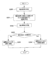
- Example 1 it is a flowchart which shows the process which acquires temperature information and electric current information.
- Example 1 it is a flowchart which shows the process which estimates the lifetime of a battery and controls the input / output of a battery pack. It is a figure which shows the correspondence of current load and temperature distribution. It is a figure which shows the temperature distribution of four areas in a specific electric current load. It is a figure which shows the threshold value used for the input / output control of an assembled battery.
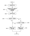
- Example 2 it is a flowchart which shows the process which estimates the lifetime of a battery and controls the input / output of a battery pack.
- FIG. 1 is a block diagram showing a drive system mounted on a vehicle.
- Examples of the vehicle of this embodiment include an electric vehicle and a hybrid vehicle.
- An electric vehicle is a vehicle that includes only an assembled battery as a power source for running the vehicle.
- a hybrid vehicle is a vehicle provided with other power sources such as an internal combustion engine and a fuel cell in addition to the assembled battery as a power source of the vehicle.
- the assembled battery 10 has a plurality of single cells electrically connected in series.
- the number of single cells can be appropriately set based on the required output of the assembled battery 10 and the like.
- the assembled battery 10 may include a plurality of single cells electrically connected in parallel.
- a secondary battery such as a nickel metal hydride battery or a lithium ion battery can be used.
- An electric double layer capacitor (capacitor) can be used instead of the secondary battery.
- the current sensor 11 detects the current during charging / discharging of the assembled battery 10 and outputs the detection result to the controller 30.
- the temperature sensor 12 detects the temperature of the assembled battery 10 and outputs the detection result to the controller 30.
- the temperature sensor 12 can be attached to one of the plurality of single cells constituting the assembled battery 10.
- the number of temperature sensors 12 can be set as appropriate. Moreover, the temperature sensor 12 can be arrange
- the assembled battery 10 is connected to a booster circuit 22 via system main relays 21a and 21b.
- the system main relays 21a and 21b are switched between ON and OFF in response to a control signal from the controller 30. If the system main relays 21a and 21b are switched from OFF to ON, the assembled battery 10 can be charged and discharged.
- the booster circuit 22 boosts the output voltage from the assembled battery 10 and supplies it to the inverter 23.
- the booster circuit 22 steps down the voltage from the inverter 23 and supplies it to the assembled battery 10.
- the controller 30 controls the operation of the booster circuit 22. In this embodiment, the booster circuit 22 is used, but the booster circuit 22 can be omitted.
- the inverter 23 converts the DC power from the booster circuit 22 into AC power and supplies it to the motor / generator 24.
- a three-phase AC motor can be used as the motor / generator 24.
- the inverter 23 converts AC power from the motor / generator 24 into DC power and supplies the DC power to the booster circuit 22.
- the controller 30 controls the operation of the inverter 23. In this embodiment, since an AC motor is used as the motor / generator 24, the inverter 23 is provided. However, if a DC motor is used, the inverter 23 can be omitted.
- the motor generator 24 receives electric power from the inverter 23 and generates kinetic energy for running the vehicle.
- the motor / generator 24 is connected to the wheels via a power transmission mechanism, and the kinetic energy generated by the motor / generator 24 is transmitted to the wheels.
- the motor generator 24 converts kinetic energy generated during braking of the vehicle into electrical energy.
- the electric energy generated by the motor / generator 24 can be stored in the assembled battery 10 as regenerative power.
- the controller 30 has a memory 31 for storing predetermined information and a timer 32 used for time measurement.
- the controller 30 includes the memory 31 and the timer 32, but the memory 31 and the timer 32 may be outside the controller 30.
- FIG. 2 is a flowchart showing control when the vehicle is driven. The process shown in FIG. 2 is executed by the controller 30.
- step S100 the controller 30 waits until the ignition switch of the vehicle is turned on from off.
- the controller 30 switches the system main relays 21a and 21b from OFF to ON.
- step S ⁇ b> 101 the controller 30 detects the temperature of the assembled battery 10 based on the output of the temperature sensor 12.
- the system main relays 21a and 21b are switched from OFF to ON, the detection operation by the temperature sensor 12 is started.
- step S102 the controller 30 detects the current during charging / discharging of the battery pack 10 based on the output of the current sensor 11. For example, the assembled battery 10 is discharged when the vehicle starts to travel or when the vehicle is accelerated. Further, when the vehicle is decelerated or stopped, the assembled battery 10 is charged. The output of the current sensor 11 changes according to the traveling pattern of the vehicle.
- step S103 the controller 30 stores the temperature information detected in step S101 and the current information detected in step S102 in the memory 31.
- the temperature information is information indicating the relationship between the temperature of the assembled battery 10 and the time when a specific temperature is generated.
- the current information is information indicating a change in current with respect to time. The time in the temperature information and current information can be measured by the timer 32.
- step S104 the controller 30 determines whether or not the ignition switch is off. If the ignition switch remains on, the process returns to step S101. Further, when the ignition switch is switched from on to off, the present process is terminated.
- the temperature information and current information of the assembled battery 10 can be acquired by performing the processing shown in FIG.
- the temperature detected by the temperature sensor 12 corresponds to the temperature of the assembled battery 10 when the vehicle is left unattended.
- the temperature of the assembled battery 10 rises due to charging / discharging of the assembled battery 10.
- the temperature of the assembled battery 10 starts to decrease.
- the degree to which the temperature of the assembled battery 10 decreases depends on the temperature of the usage environment of the assembled battery 10. If the vehicle is left for a long time, the temperature of the assembled battery 10 is unlikely to change.
- the temperature of the assembled battery 10 is detected by the temperature sensor 12 when the ignition switch is switched from OFF to ON again, the temperature of the assembled battery 10 when the vehicle is stopped can be acquired.
- the temperature of the assembled battery 10 is the temperature when the vehicle is traveling, in other words, the temperature when the assembled battery 10 is charged / discharged, and the temperature when the vehicle is stopped (leaved), in other words, And the temperature when charging / discharging of the assembled battery 10 is prohibited.
- the temperature of the assembled battery 10 can be obtained by detecting the temperature of the assembled battery 10 with the temperature sensor 12. it can. Further, based on the output of the temperature sensor 12 while the ignition switch is on, the temperature of the assembled battery 10 when the vehicle is traveling can be acquired.
- FIG. 3 is a flowchart showing a process for estimating the life of the assembled battery 10 and controlling the input / output of the assembled battery 10. The process shown in FIG. 3 is executed by the controller 30.
- step S200 the controller 30 specifies the current load of the assembled battery 10.
- the current load can be expressed as the square of the current, and the current load can be specified based on the current information stored in the memory 31 in step S103 of FIG.
- the current load can be used as information for specifying the traveling state of the vehicle. Since the current load changes depending on the traveling state of the vehicle, the traveling state of the vehicle can be identified by identifying the current load.
- step S201 the controller 30 causes the vehicle to travel based on the temperature distribution corresponding to the current load specified in step S200 and the temperature information stored in the memory 31 (steps S101 and S103 in FIG. 2). Identify the region (corresponding to the usage environment).
- the memory 31 stores data indicating the correspondence between the current loads CL1 to CLn and the temperature distributions TD1 to TDn. Correspondence relationships between the current loads CL1 to CLn and the temperature distributions TD1 to TDn can be acquired in advance by actual measurement.
- the current load according to the actual traveling state of the vehicle can be specified from the current loads CL1 to CLn by the process of step S200.
- Each temperature distribution corresponding to each current load CL1 to CLn is expressed as a temperature distribution shown in FIG.
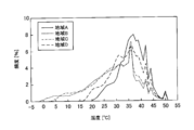
- FIG. 5 shows a temperature distribution corresponding to a specific current load.
- FIG. 5 shows the temperature distribution of the battery pack 10 when the vehicle is driven in a specific driving state (current load) in the four areas A to D.
- the horizontal axis is the temperature of the assembled battery 10
- the vertical axis is the frequency. The frequency indicates a ratio of time when a specific temperature is generated with respect to the total time.
- the temperature change of the assembled battery 10 behaves similar to each other regardless of the regions A to D.
- the temperature of the assembled battery 10 is in a low temperature range, the temperature distribution varies greatly depending on the regions A to D.
- the temperature of the assembled battery 10 in the low temperature region corresponds to the temperature of the assembled battery 10 when the vehicle is left unattended. Therefore, if the temperature distribution of the assembled battery 10 immediately after leaving the assembled battery 10 is obtained, the region (any one of the areas A to D) in which the vehicle is traveling is specified based on the temperature distribution shown in FIG. be able to.
- the controller 30 can specify the area showing this temperature distribution. Further, when there is no temperature distribution that matches the temperature distribution obtained by the process of FIG. 2, the controller 30 selects the temperature closest to the temperature distribution obtained by the process of FIG. Distribution can be specified. The determination as to whether or not the temperature distributions match may be made by comparing the temperature distributions in the low temperature range described above.
- FIG. 5 shows the temperature distributions in the four areas A to D, but the number of areas representing the temperature distribution can be set as appropriate. When a difference in temperature distribution that is easy to distinguish occurs in the low temperature region, the temperature distribution in this region may be acquired.
- the temperature distributions TD1 to TDn corresponding to the current loads CL1 to CLn are specified, but the present invention is not limited to this. That is, by omitting the specification of the current load and specifying the temperature distribution that matches the temperature distribution obtained by the processing of FIG. 2 from the plurality of temperature distributions prepared in advance regardless of the current load, Can also be specified.
- step S202 the controller 30 specifies (estimates) the lifetime of the assembled battery 10 based on the temperature distribution in the area specified in step S201.
- the life of the assembled battery 10 refers to the time until the deterioration state of the assembled battery 10 reaches a state where charging / discharging of the assembled battery 10 is prohibited.
- the deterioration state of the assembled battery 10 can be represented by, for example, the rate of change in resistance of the assembled battery 10.
- the resistance of the assembled battery 10 can be calculated by detecting the voltage and current of the assembled battery 10.
- the state which prohibits charging / discharging of the assembled battery 10 can be set suitably.
- the correspondence relationship between the temperature distribution of the assembled battery 10 and the lifetime of the assembled battery 10 can be determined in advance by experiments, and data indicating this correspondence relationship can be stored in the memory 31. If the correspondence relationship between the temperature distribution and the lifetime is used, the lifetime of the assembled battery 10 can be specified based on the temperature distribution in the area specified in step S201. In addition, the lifetime of the assembled battery 10 can also be calculated based on an arithmetic expression using the temperature distribution of the assembled battery 10 as a parameter.
- step S203 the controller 30 determines whether or not the lifetime (estimated lifetime) of the assembled battery 10 estimated in step S202 exceeds the target lifetime.
- the target life is the target life of the assembled battery 10 and can be set as appropriate.
- the process proceeds to step S204. Otherwise, the process proceeds to step S205.
- step S204 the controller 30 relaxes the input / output restrictions of the assembled battery 10.
- Input / output (charge / discharge) of the assembled battery 10 is controlled based on threshold values Win (ref) and Wout (ref) shown in FIG. That is, the controller 30 controls charging / discharging of the assembled battery 10 so that the input / output of the assembled battery 10 does not exceed the threshold values Win (ref) and Wout (ref).
- the horizontal axis indicates the temperature of the assembled battery 10
- the vertical axis indicates the input / output of the assembled battery 10.
- the input Win of the assembled battery 10 corresponds to charging of the assembled battery 10
- the output Wout of the assembled battery 10 corresponds to discharging of the assembled battery 10.
- the threshold values Win (ref) and Wout (ref) shown in FIG. 6 are examples, and are not limited thereto.
- the controller 30 shifts the threshold values Win (ref) and Wout (ref) in the direction of the arrow D1 by relaxing the restriction on the input / output of the assembled battery 10.
- the amounts by which the threshold values Win (ref) and Wout (ref) are shifted in the direction of the arrow D1 may be the same or different.
- step S205 the controller 30 further restricts input / output of the assembled battery 10. Specifically, the controller 30 shifts the threshold values Win (ref) and Wout (ref) shown in FIG. 6 in the direction of the arrow D2.
- the amounts by which the threshold values Win (ref) and Wout (ref) are shifted in the direction of the arrow D2 may be the same or different.
- step S205 If the vehicle is a hybrid vehicle, input / output of the assembled battery 10 can be prohibited in step S205. Even if input / output of the battery pack 10 is prohibited, the vehicle can be driven by another power source.
- the use area of the assembled battery 10 can be specified by comparing the temperature distribution for each area shown in FIG. 5 with the temperature distribution acquired from the output of the temperature sensor 12. If the use area of the assembled battery 10 can be specified, the deterioration state of the assembled battery 10 can be estimated in consideration of the temperature distribution in the use area.
- the temperature distribution in the area of use mainly affects the temperature of the assembled battery 10 when the vehicle is left, and the deterioration state of the assembled battery 10 depends on the temperature of the assembled battery 10 when the vehicle is left. Also changes. Therefore, the accuracy of estimating the deterioration state of the assembled battery 10 can be improved by taking into account the temperature distribution in the area of use.
- FIG. 7 is a flowchart illustrating a process for estimating the life of the assembled battery 10 and controlling input / output of the assembled battery 10.
- the same reference numerals are used for the same configurations as those described in the first embodiment.
- the process shown in FIG. 7 is executed by the controller 30.
- Example 1 the input / output of the assembled battery 10 is further restricted or the restriction of the input / output is further relaxed depending on whether or not the estimated life of the assembled battery 10 exceeds the target life.
- the input / output of the assembled battery 10 is further restricted or the restriction of the input / output is further relaxed depending on whether or not the estimated life of the assembled battery 10 exceeds the target life.
- step S200 to step S205 is the same as the processing described in the first embodiment (FIG. 3).
- step S203 when the estimated life of the assembled battery 10 exceeds the target life in step S203, the process proceeds to step S205, and otherwise, the process proceeds to step S206.
- step S206 the controller 30 determines whether or not the travel distance of the vehicle exceeds the target distance.
- the controller 30 can acquire the travel distance of the vehicle using a travel distance meter.
- the controller 30 performs the process of step S205. Further, when the travel distance does not exceed the target distance, the controller 30 performs the process of step S204.
- Example 3 of the present invention will be described.
- the temperature distribution shown in FIG. 5 includes the temperature of the assembled battery 10 when the ignition switch is switched from off to on, and the temperature of the assembled battery 10 while the ignition switch is on. Yes.
- the temperature distribution for identifying the region is used as the temperature distribution for identifying the region (temperature distribution corresponding to FIG. 5).
- the temperature distribution in the low temperature region may be compared to specify the region. That is, attention should be paid to the temperature distribution of the assembled battery 10 when the ignition switch is switched from OFF to ON. For this reason, in the present embodiment, the temperature distribution of the assembled battery 10 when the ignition switch is switched from OFF to ON is used as information corresponding to the temperature distribution of FIG.
- the horizontal axis indicates the temperature of the assembled battery 10 and the vertical axis indicates the frequency, as in FIG.
- the use region of the assembled battery 10 can be specified based on the temperature distribution of the assembled battery 10. And the deterioration state of the assembled battery 10 can be estimated by specifying the use area of the assembled battery 10.
- the temperature of the assembled battery 10 detected by the temperature sensor 12 can be used for temperature adjustment of the assembled battery 10. Specifically, when the temperature of the assembled battery 10 rises, the temperature rise of the assembled battery 10 can be suppressed by driving the blower and supplying cooling air to the assembled battery 10. Moreover, when the temperature of the assembled battery 10 falls, the temperature fall of the assembled battery 10 can be suppressed by supplying the heating air to the assembled battery 10.
- Embodiments 1 to 3 described above the case where the assembled battery 10 is mounted on a vehicle has been described.
- the present invention is not limited to this. That is, the present invention can be applied to any device on which the assembled battery 10 is mounted. Even when the assembled battery 10 is mounted on a device other than the vehicle, the deterioration state of the assembled battery 10 changes according to the temperature in the area where the assembled battery 10 is used. Therefore, in a device on which the assembled battery 10 is mounted, the use region of the assembled battery 10 can be specified and the deterioration state of the assembled battery 10 can be estimated, as in the first to third embodiments.
- the assembled battery 10 including a plurality of single cells is used, but the present invention is not limited to this. That is, the present invention can be applied even when a single battery is used.
Landscapes
- Engineering & Computer Science (AREA)
- Chemical & Material Sciences (AREA)
- Transportation (AREA)
- Manufacturing & Machinery (AREA)
- Electrochemistry (AREA)
- General Chemical & Material Sciences (AREA)
- Mechanical Engineering (AREA)
- Chemical Kinetics & Catalysis (AREA)
- Power Engineering (AREA)
- Sustainable Energy (AREA)
- Sustainable Development (AREA)
- Life Sciences & Earth Sciences (AREA)
- General Physics & Mathematics (AREA)
- Physics & Mathematics (AREA)
- Microelectronics & Electronic Packaging (AREA)
- Combustion & Propulsion (AREA)
- Automation & Control Theory (AREA)
- Secondary Cells (AREA)
- Electric Propulsion And Braking For Vehicles (AREA)
- Battery Mounting, Suspending (AREA)
Abstract
Description
Claims (16)
- 負荷と接続され、充放電を行う蓄電装置と、
前記蓄電装置が前記負荷と接続されることに応じて、前記蓄電装置の温度を検出する温度センサと、
前記蓄電装置の使用環境における温度情報に基づいて、前記蓄電装置の劣化状態を推定するコントローラと、を有し、
前記コントローラは、前記蓄電装置および前記負荷を接続したときの前記温度センサの出力に基づいて前記蓄電装置の温度分布を取得し、取得した温度分布に対応した前記蓄電装置の使用環境を特定することを特徴とする蓄電システム。 - 前記コントローラは、複数の使用環境における前記蓄電装置の温度分布の中から、前記温度センサの出力に基づいて取得した温度分布に沿った温度分布を特定することにより、前記蓄電装置の使用環境を特定することを特徴とする請求項1に記載の蓄電システム。
- 前記蓄電装置の充放電時の電流を検出する電流センサを有しており、
前記コントローラは、前記電流センサの検出結果に対応した、複数の使用環境における前記蓄電装置の温度分布を特定することを特徴とする請求項2に記載の蓄電システム。 - 複数の使用環境における前記蓄電装置の温度分布を、前記電流センサの検出結果毎に記憶するメモリを有しており、
前記コントローラは、前記電流センサの出力および前記メモリの記憶情報を用いて、前記電流センサの検出結果に対応した、複数の使用環境における前記蓄電装置の温度分布を特定することを特徴とする請求項3に記載の蓄電システム。 - 前記コントローラは、前記劣化状態として、前記蓄電装置の寿命を推定することを特徴とする請求項1から4のいずれか1つに記載の蓄電システム。
- 前記コントローラは、前記蓄電装置の推定寿命が目標寿命よりも短いときには、前記蓄電装置の入出力を制限することを特徴とする請求項5に記載の蓄電システム。
- 前記コントローラは、前記蓄電装置の推定寿命が目標寿命よりも長いときには、前記蓄電装置の入出力の制限を緩和することを特徴とする請求項5又は6に記載の蓄電システム。
- 前記蓄電装置は、電気的に直列に接続された複数の蓄電素子を有することを特徴とする請求項1から7のいずれか1つに記載の蓄電システム。
- 前記蓄電装置は、車両に搭載され、車両の走行に用いられるエネルギを出力することを特徴とする請求項1から8のいずれか1つに記載の蓄電システム。
- 前記蓄電装置の温度分布は、前記蓄電装置の温度と、前記蓄電装置の温度毎の発生頻度との関係を示すことを特徴とする請求項1から9のいずれか1つに記載の蓄電システム。
- 充放電を行う蓄電装置が負荷と接続されることに応じて、前記蓄電装置の温度を検出する第1ステップと、
前記蓄電装置および前記負荷を接続したときの前記第1ステップの検出結果に基づいて前記蓄電装置の温度分布を取得し、取得した温度分布に対応した前記蓄電装置の使用環境を特定する第2ステップと、
前記第2ステップで特定した前記蓄電装置の使用環境における温度情報に基づいて、前記蓄電装置の劣化状態を推定する第3ステップと、
を有することを特徴とする推定方法。 - 前記第2ステップにおいて、複数の使用環境における前記蓄電装置の温度分布の中から、前記第1ステップの検出結果に基づいて取得した温度分布に沿った温度分布を特定することにより、前記蓄電装置の使用環境を特定することを特徴とする請求項11に記載の推定方法。
- 前記蓄電装置の充放電時の電流を検出する第4ステップを有しており、
前記第2ステップにおいて、前記第4ステップの検出結果に対応した、複数の使用環境における前記蓄電装置の温度分布を特定することを特徴とする請求項12に記載の推定方法。 - 複数の使用環境における前記蓄電装置の温度分布を、前記第4ステップの検出結果毎に記憶するメモリの記憶情報と、前記第4ステップの検出結果とを用いて、前記第4ステップの検出結果に対応した、複数の使用環境における前記蓄電装置の温度分布を特定することを特徴とする請求項13に記載の推定方法。
- 前記第3ステップにおいて、前記劣化状態として、前記蓄電装置の寿命を推定することを特徴とする請求項11から14のいずれか1つに記載の推定方法。
- 前記蓄電装置の温度分布は、前記蓄電装置の温度と、前記蓄電装置の温度毎の発生頻度との関係を示すことを特徴とする請求項11から15のいずれか1つに記載の推定方法。
Priority Applications (6)
| Application Number | Priority Date | Filing Date | Title |
|---|---|---|---|
| CN2011800659155A CN103339785A (zh) | 2011-01-24 | 2011-01-24 | 蓄电系统 |
| EP20110856727 EP2669987A4 (en) | 2011-01-24 | 2011-01-24 | ENERGY STORAGE SYSTEM |
| JP2012523759A JP5105031B2 (ja) | 2011-01-24 | 2011-01-24 | 蓄電システム |
| KR1020137003266A KR20130033449A (ko) | 2011-01-24 | 2011-01-24 | 축전 시스템 |
| PCT/JP2011/000351 WO2012101667A1 (ja) | 2011-01-24 | 2011-01-24 | 蓄電システム |
| US13/811,829 US20130294479A1 (en) | 2011-01-24 | 2011-01-24 | Electric storage system |
Applications Claiming Priority (1)
| Application Number | Priority Date | Filing Date | Title |
|---|---|---|---|
| PCT/JP2011/000351 WO2012101667A1 (ja) | 2011-01-24 | 2011-01-24 | 蓄電システム |
Publications (1)
| Publication Number | Publication Date |
|---|---|
| WO2012101667A1 true WO2012101667A1 (ja) | 2012-08-02 |
Family
ID=46580283
Family Applications (1)
| Application Number | Title | Priority Date | Filing Date |
|---|---|---|---|
| PCT/JP2011/000351 Ceased WO2012101667A1 (ja) | 2011-01-24 | 2011-01-24 | 蓄電システム |
Country Status (6)
| Country | Link |
|---|---|
| US (1) | US20130294479A1 (ja) |
| EP (1) | EP2669987A4 (ja) |
| JP (1) | JP5105031B2 (ja) |
| KR (1) | KR20130033449A (ja) |
| CN (1) | CN103339785A (ja) |
| WO (1) | WO2012101667A1 (ja) |
Cited By (3)
| Publication number | Priority date | Publication date | Assignee | Title |
|---|---|---|---|---|
| JP2015154671A (ja) * | 2014-02-18 | 2015-08-24 | トヨタ自動車株式会社 | 蓄電システム |
| JP2016163532A (ja) * | 2015-03-05 | 2016-09-05 | 日立オートモティブシステムズ株式会社 | 電池管理装置、電池システムおよびハイブリッド車両制御システム |
| JP2023136055A (ja) * | 2022-03-16 | 2023-09-29 | いすゞ自動車株式会社 | 車載のバッテリーの制御装置 |
Families Citing this family (11)
| Publication number | Priority date | Publication date | Assignee | Title |
|---|---|---|---|---|
| JP5626040B2 (ja) * | 2011-03-09 | 2014-11-19 | トヨタ自動車株式会社 | 電池管理装置および電池管理システム |
| US9697652B2 (en) * | 2013-04-22 | 2017-07-04 | Volvo Truck Corporation | Method for monitoring state of health of a vehicle system |
| JP6505697B2 (ja) * | 2013-08-06 | 2019-04-24 | ゴゴロ インク | 電気エネルギー貯蔵装置の温度プロファイルに基づく電気車両システムの調整 |
| CN105467324B (zh) * | 2014-09-30 | 2020-03-03 | 株式会社杰士汤浅国际 | 电池劣化判定装置、电池劣化判定方法以及电池组 |
| JP6229671B2 (ja) * | 2015-01-29 | 2017-11-15 | トヨタ自動車株式会社 | 二次電池管理システム |
| JP6887718B2 (ja) | 2015-06-05 | 2021-06-16 | ゴゴロ インク | 車両、及び、電動車両の負荷の特定の種類を判定する方法 |
| JP6735359B2 (ja) * | 2016-02-02 | 2020-08-05 | トヨタ・モーター・ヨーロッパToyota Motor Europe | 蓄電池充電のための制御装置および蓄電池を充電する方法 |
| US10962598B2 (en) * | 2016-08-05 | 2021-03-30 | Gs Yuasa International Ltd. | Energy storage device state estimation device and energy storage device state estimation method |
| JP7254597B2 (ja) * | 2019-04-12 | 2023-04-10 | 株式会社日立製作所 | 電池システム、鉄道車両および電池管理方法 |
| CN113978311B (zh) * | 2021-10-15 | 2024-05-17 | 潍柴动力股份有限公司 | 一种电池温度修正方法、装置及电子设备 |
| CN114559819B (zh) * | 2022-01-25 | 2023-10-13 | 重庆标能瑞源储能技术研究院有限公司 | 一种基于信号处理的电动汽车电池安全预警方法 |
Citations (10)
| Publication number | Priority date | Publication date | Assignee | Title |
|---|---|---|---|---|
| JPH1051968A (ja) * | 1996-08-05 | 1998-02-20 | Nissan Motor Co Ltd | 電池の充電方法 |
| JP2002157361A (ja) | 2000-11-22 | 2002-05-31 | Densei Lambda Kk | 交換時期通知方法、交換時期通知システム、交換時期通知装置および交換時期通知プログラム |
| JP2003047110A (ja) | 2001-05-09 | 2003-02-14 | Ford Global Technol Inc | 車両エネルギー管理のためにハイブリッド電気自動車に車載ナビゲーション・システムを用いる方法 |
| JP2007074891A (ja) | 2005-08-08 | 2007-03-22 | Toyota Motor Corp | パワートレイン用の電池寿命予知装置及び電池寿命警告装置 |
| JP2007230398A (ja) * | 2006-03-01 | 2007-09-13 | Fujitsu Ten Ltd | バッテリ監視装置及びバッテリ監視方法 |
| JP2008126788A (ja) | 2006-11-20 | 2008-06-05 | Toyota Motor Corp | 車両用電池寿命判定装置及び電池寿命判定システム |
| JP2010002365A (ja) * | 2008-06-23 | 2010-01-07 | Aisin Aw Co Ltd | 車載ナビゲーションシステム |
| JP2010035280A (ja) * | 2008-07-25 | 2010-02-12 | Toyota Motor Corp | 電源システムおよびそれを備えた車両 |
| JP2010045901A (ja) | 2008-08-11 | 2010-02-25 | Panasonic Ev Energy Co Ltd | 車両制御システム及び車両用制御装置 |
| JP2010139396A (ja) | 2008-12-12 | 2010-06-24 | Panasonic Corp | 電池寿命検出装置、蓄電装置、及び電池寿命検出方法 |
Family Cites Families (6)
| Publication number | Priority date | Publication date | Assignee | Title |
|---|---|---|---|---|
| US7429849B2 (en) * | 2003-11-26 | 2008-09-30 | Toyo System Co., Ltd. | Method and apparatus for confirming the charge amount and degradation state of a battery, a storage medium, an information processing apparatus, and an electronic apparatus |
| JP4810803B2 (ja) * | 2004-07-13 | 2011-11-09 | トヨタ自動車株式会社 | 電源装置 |
| JP5050325B2 (ja) * | 2005-07-12 | 2012-10-17 | 日産自動車株式会社 | 組電池用制御装置 |
| JP4864383B2 (ja) * | 2005-08-24 | 2012-02-01 | 富士重工業株式会社 | 蓄電デバイスの劣化状態推定装置 |
| JP2007311065A (ja) * | 2006-05-16 | 2007-11-29 | Toyota Motor Corp | 電池装置、これを搭載した車両、および電池装置の異常判定方法 |
| WO2011037257A1 (ja) * | 2009-09-28 | 2011-03-31 | 日立ビークルエナジー株式会社 | 電池システム |
-
2011
- 2011-01-24 KR KR1020137003266A patent/KR20130033449A/ko not_active Ceased
- 2011-01-24 EP EP20110856727 patent/EP2669987A4/en not_active Withdrawn
- 2011-01-24 CN CN2011800659155A patent/CN103339785A/zh active Pending
- 2011-01-24 JP JP2012523759A patent/JP5105031B2/ja active Active
- 2011-01-24 WO PCT/JP2011/000351 patent/WO2012101667A1/ja not_active Ceased
- 2011-01-24 US US13/811,829 patent/US20130294479A1/en not_active Abandoned
Patent Citations (10)
| Publication number | Priority date | Publication date | Assignee | Title |
|---|---|---|---|---|
| JPH1051968A (ja) * | 1996-08-05 | 1998-02-20 | Nissan Motor Co Ltd | 電池の充電方法 |
| JP2002157361A (ja) | 2000-11-22 | 2002-05-31 | Densei Lambda Kk | 交換時期通知方法、交換時期通知システム、交換時期通知装置および交換時期通知プログラム |
| JP2003047110A (ja) | 2001-05-09 | 2003-02-14 | Ford Global Technol Inc | 車両エネルギー管理のためにハイブリッド電気自動車に車載ナビゲーション・システムを用いる方法 |
| JP2007074891A (ja) | 2005-08-08 | 2007-03-22 | Toyota Motor Corp | パワートレイン用の電池寿命予知装置及び電池寿命警告装置 |
| JP2007230398A (ja) * | 2006-03-01 | 2007-09-13 | Fujitsu Ten Ltd | バッテリ監視装置及びバッテリ監視方法 |
| JP2008126788A (ja) | 2006-11-20 | 2008-06-05 | Toyota Motor Corp | 車両用電池寿命判定装置及び電池寿命判定システム |
| JP2010002365A (ja) * | 2008-06-23 | 2010-01-07 | Aisin Aw Co Ltd | 車載ナビゲーションシステム |
| JP2010035280A (ja) * | 2008-07-25 | 2010-02-12 | Toyota Motor Corp | 電源システムおよびそれを備えた車両 |
| JP2010045901A (ja) | 2008-08-11 | 2010-02-25 | Panasonic Ev Energy Co Ltd | 車両制御システム及び車両用制御装置 |
| JP2010139396A (ja) | 2008-12-12 | 2010-06-24 | Panasonic Corp | 電池寿命検出装置、蓄電装置、及び電池寿命検出方法 |
Non-Patent Citations (1)
| Title |
|---|
| See also references of EP2669987A4 |
Cited By (5)
| Publication number | Priority date | Publication date | Assignee | Title |
|---|---|---|---|---|
| JP2015154671A (ja) * | 2014-02-18 | 2015-08-24 | トヨタ自動車株式会社 | 蓄電システム |
| US10295610B2 (en) | 2014-02-18 | 2019-05-21 | Toyota Jidosha Kabushiki Kaisha | Electric power storage system for a vehicle and method for controlling electric power storage system for a vehicle |
| JP2016163532A (ja) * | 2015-03-05 | 2016-09-05 | 日立オートモティブシステムズ株式会社 | 電池管理装置、電池システムおよびハイブリッド車両制御システム |
| JP2023136055A (ja) * | 2022-03-16 | 2023-09-29 | いすゞ自動車株式会社 | 車載のバッテリーの制御装置 |
| JP7476917B2 (ja) | 2022-03-16 | 2024-05-01 | いすゞ自動車株式会社 | 車載のバッテリーの制御装置 |
Also Published As
| Publication number | Publication date |
|---|---|
| CN103339785A (zh) | 2013-10-02 |
| JP5105031B2 (ja) | 2012-12-19 |
| US20130294479A1 (en) | 2013-11-07 |
| JPWO2012101667A1 (ja) | 2014-06-30 |
| EP2669987A1 (en) | 2013-12-04 |
| KR20130033449A (ko) | 2013-04-03 |
| EP2669987A4 (en) | 2014-09-03 |
Similar Documents
| Publication | Publication Date | Title |
|---|---|---|
| JP5105031B2 (ja) | 蓄電システム | |
| US9533585B2 (en) | Vehicle | |
| US9849793B2 (en) | Electrical storage system for vehicle | |
| JP5772965B2 (ja) | 非水二次電池の制御装置および制御方法 | |
| JP5321757B2 (ja) | 蓄電装置の制御装置および制御方法 | |
| US10286806B2 (en) | Electrical storage system | |
| KR101245788B1 (ko) | 배터리의 작동점 제어 방법 및 장치 | |
| JP5470829B2 (ja) | リチウムイオン電池の状態を判別する判別装置 | |
| JP5747856B2 (ja) | 電池システムおよび充放電制御方法 | |
| WO2015028865A2 (en) | Electrical storage system | |
| WO2014167914A1 (ja) | バッテリ充電システム及びバッテリ充電方法 | |
| JP5720554B2 (ja) | 非水二次電池の制御装置および制御方法 | |
| JP2017071299A (ja) | 蓄電装置の充放電制御装置 | |
| JP2022132933A (ja) | バッテリ充放電制御システム及びバッテリ充放電制御方法 | |
| JP5862478B2 (ja) | 蓄電システムおよび制御方法 | |
| JP5842607B2 (ja) | 非水二次電池の制御装置および制御方法 | |
| JP5092903B2 (ja) | 車両用電池の充放電制御装置 | |
| US10283980B2 (en) | Electrical storage system | |
| JP2014155401A (ja) | 蓄電システム |
Legal Events
| Date | Code | Title | Description |
|---|---|---|---|
| WWE | Wipo information: entry into national phase |
Ref document number: 2012523759 Country of ref document: JP |
|
| 121 | Ep: the epo has been informed by wipo that ep was designated in this application |
Ref document number: 11856727 Country of ref document: EP Kind code of ref document: A1 |
|
| WWE | Wipo information: entry into national phase |
Ref document number: 13811829 Country of ref document: US |
|
| ENP | Entry into the national phase |
Ref document number: 20137003266 Country of ref document: KR Kind code of ref document: A |
|
| REEP | Request for entry into the european phase |
Ref document number: 2011856727 Country of ref document: EP |
|
| WWE | Wipo information: entry into national phase |
Ref document number: 2011856727 Country of ref document: EP |
|
| NENP | Non-entry into the national phase |
Ref country code: DE |