WO2012101888A1 - 医療機器 - Google Patents
医療機器 Download PDFInfo
- Publication number
- WO2012101888A1 WO2012101888A1 PCT/JP2011/075686 JP2011075686W WO2012101888A1 WO 2012101888 A1 WO2012101888 A1 WO 2012101888A1 JP 2011075686 W JP2011075686 W JP 2011075686W WO 2012101888 A1 WO2012101888 A1 WO 2012101888A1
- Authority
- WO
- WIPO (PCT)
- Prior art keywords
- image
- medical device
- tip
- superimposed
- distal end
- Prior art date
- Legal status (The legal status is an assumption and is not a legal conclusion. Google has not performed a legal analysis and makes no representation as to the accuracy of the status listed.)
- Ceased
Links
Images









Classifications
-
- A—HUMAN NECESSITIES
- A61—MEDICAL OR VETERINARY SCIENCE; HYGIENE
- A61B—DIAGNOSIS; SURGERY; IDENTIFICATION
- A61B1/00—Instruments for performing medical examinations of the interior of cavities or tubes of the body by visual or photographical inspection, e.g. endoscopes; Illuminating arrangements therefor
- A61B1/00002—Operational features of endoscopes
- A61B1/00043—Operational features of endoscopes provided with output arrangements
- A61B1/00045—Display arrangement
- A61B1/0005—Display arrangement combining images e.g. side-by-side, superimposed or tiled
-
- A—HUMAN NECESSITIES
- A61—MEDICAL OR VETERINARY SCIENCE; HYGIENE
- A61B—DIAGNOSIS; SURGERY; IDENTIFICATION
- A61B34/00—Computer-aided surgery; Manipulators or robots specially adapted for use in surgery
- A61B34/20—Surgical navigation systems; Devices for tracking or guiding surgical instruments, e.g. for frameless stereotaxis
-
- A—HUMAN NECESSITIES
- A61—MEDICAL OR VETERINARY SCIENCE; HYGIENE
- A61B—DIAGNOSIS; SURGERY; IDENTIFICATION
- A61B34/00—Computer-aided surgery; Manipulators or robots specially adapted for use in surgery
- A61B34/20—Surgical navigation systems; Devices for tracking or guiding surgical instruments, e.g. for frameless stereotaxis
- A61B2034/2046—Tracking techniques
- A61B2034/2051—Electromagnetic tracking systems
-
- A—HUMAN NECESSITIES
- A61—MEDICAL OR VETERINARY SCIENCE; HYGIENE
- A61B—DIAGNOSIS; SURGERY; IDENTIFICATION
- A61B90/00—Instruments, implements or accessories specially adapted for surgery or diagnosis and not covered by any of the groups A61B1/00 - A61B50/00, e.g. for luxation treatment or for protecting wound edges
- A61B90/36—Image-producing devices or illumination devices not otherwise provided for
- A61B2090/364—Correlation of different images or relation of image positions in respect to the body
- A61B2090/365—Correlation of different images or relation of image positions in respect to the body augmented reality, i.e. correlating a live optical image with another image
-
- A—HUMAN NECESSITIES
- A61—MEDICAL OR VETERINARY SCIENCE; HYGIENE
- A61B—DIAGNOSIS; SURGERY; IDENTIFICATION
- A61B90/00—Instruments, implements or accessories specially adapted for surgery or diagnosis and not covered by any of the groups A61B1/00 - A61B50/00, e.g. for luxation treatment or for protecting wound edges
- A61B90/36—Image-producing devices or illumination devices not otherwise provided for
- A61B90/37—Surgical systems with images on a monitor during operation
- A61B2090/378—Surgical systems with images on a monitor during operation using ultrasound
-
- A—HUMAN NECESSITIES
- A61—MEDICAL OR VETERINARY SCIENCE; HYGIENE
- A61B—DIAGNOSIS; SURGERY; IDENTIFICATION
- A61B34/00—Computer-aided surgery; Manipulators or robots specially adapted for use in surgery
- A61B34/25—User interfaces for surgical systems
-
- A—HUMAN NECESSITIES
- A61—MEDICAL OR VETERINARY SCIENCE; HYGIENE
- A61B—DIAGNOSIS; SURGERY; IDENTIFICATION
- A61B6/00—Apparatus or devices for radiation diagnosis; Apparatus or devices for radiation diagnosis combined with radiation therapy equipment
- A61B6/02—Arrangements for diagnosis sequentially in different planes; Stereoscopic radiation diagnosis
- A61B6/03—Computed tomography [CT]
- A61B6/032—Transmission computed tomography [CT]
-
- A—HUMAN NECESSITIES
- A61—MEDICAL OR VETERINARY SCIENCE; HYGIENE
- A61B—DIAGNOSIS; SURGERY; IDENTIFICATION
- A61B6/00—Apparatus or devices for radiation diagnosis; Apparatus or devices for radiation diagnosis combined with radiation therapy equipment
- A61B6/46—Arrangements for interfacing with the operator or the patient
- A61B6/461—Displaying means of special interest
- A61B6/466—Displaying means of special interest adapted to display 3D data
-
- A—HUMAN NECESSITIES
- A61—MEDICAL OR VETERINARY SCIENCE; HYGIENE
- A61B—DIAGNOSIS; SURGERY; IDENTIFICATION
- A61B8/00—Diagnosis using ultrasonic, sonic or infrasonic waves
- A61B8/52—Devices using data or image processing specially adapted for diagnosis using ultrasonic, sonic or infrasonic waves
- A61B8/5215—Devices using data or image processing specially adapted for diagnosis using ultrasonic, sonic or infrasonic waves involving processing of medical diagnostic data
- A61B8/523—Devices using data or image processing specially adapted for diagnosis using ultrasonic, sonic or infrasonic waves involving processing of medical diagnostic data for generating planar views from image data in a user selectable plane not corresponding to the acquisition plane
-
- A—HUMAN NECESSITIES
- A61—MEDICAL OR VETERINARY SCIENCE; HYGIENE
- A61B—DIAGNOSIS; SURGERY; IDENTIFICATION
- A61B8/00—Diagnosis using ultrasonic, sonic or infrasonic waves
- A61B8/52—Devices using data or image processing specially adapted for diagnosis using ultrasonic, sonic or infrasonic waves
- A61B8/5215—Devices using data or image processing specially adapted for diagnosis using ultrasonic, sonic or infrasonic waves involving processing of medical diagnostic data
- A61B8/5238—Devices using data or image processing specially adapted for diagnosis using ultrasonic, sonic or infrasonic waves involving processing of medical diagnostic data for combining image data of patient, e.g. merging several images from different acquisition modes into one image
- A61B8/5261—Devices using data or image processing specially adapted for diagnosis using ultrasonic, sonic or infrasonic waves involving processing of medical diagnostic data for combining image data of patient, e.g. merging several images from different acquisition modes into one image combining images from different diagnostic modalities, e.g. ultrasound and X-ray
Definitions
- Embodiments of the present invention relate to a medical device that is inserted into a lumen of a subject, and more particularly, to a medical device that performs highly accurate examination / treatment based on three-dimensional image data of a subject.
- diagnosis using three-dimensional images has been widely performed. For example, by capturing a tomographic image of a subject with an X-ray CT (Computed Tomography) apparatus, three-dimensional image data in the subject is obtained, and a target region is diagnosed using the three-dimensional image data. It has become.
- X-ray CT Computed Tomography
- the subject is continuously moved while continuously rotating the X-ray irradiation position and the detection position, thereby subjecting the subject to a helical continuous scan (helical scan). Then, a three-dimensional image is formed from a large number of two-dimensional tomographic images of consecutive subjects.
- One of the three-dimensional images used for diagnosis is a three-dimensional image of the lung bronchus.
- the three-dimensional image of the bronchus is used to three-dimensionally grasp the position of an abnormal part suspected of lung cancer, for example.
- a bronchoscope is inserted and a biopsy needle or biopsy forceps is protruded from the distal end of the insertion part to collect a tissue sample.
- Japanese Laid-Open Patent Publication No. 2004-180940 and Japanese Laid-Open Patent Publication No. 2005-131042 disclose a three-dimensional image of a duct in the subject based on three-dimensional image data of the subject.
- Japanese Patent Application Laid-Open No. 2003-265408 discloses an endoscope guidance device that superimposes and displays the position of the distal end portion of an endoscope on a tomographic image.
- the known insertion navigation system may not be able to easily insert the distal end of the insertion portion to the target site.
- Embodiment of this invention aims at providing the medical device which is easy to insert the front-end
- a medical device includes an insertion unit that is inserted into a lumen of a subject, a storage unit that stores three-dimensional image data of the subject acquired in advance, and the insertion unit within the lumen
- Position calculation means for calculating the position and direction of the distal end portion of the limb, and path generation means for generating an insertion path for inserting the distal end portion to the target position via the lumen based on the three-dimensional image
- a tomographic image generating means for generating a tomographic image based on the position and direction of the tip from the three-dimensional image data
- a superimposed image generating means for generating a superimposed image by superimposing the insertion path and the tomographic image
- Display means for displaying the superimposed image.
- FIG. 1 is a three-dimensional model diagram showing a state where the insertion portion 2A is being inserted toward the target site 9G.
- the insertion portion 2A has a channel 8 that passes through the inside thereof, and the treatment tool 6 inserted from the channel insertion port 8A protrudes from the distal end portion 2C to perform a biopsy of the target site 9G.
- the Z-axis direction is the body axis of the subject 7
- the X-axis direction is the left-right direction of the subject 7
- the Y-axis direction is the front-rear direction of the subject 7.
- a superimposed image PW1 which is a three-dimensional model image showing a three-dimensional space in which R and N are superimposed and displayed, is displayed on the display unit 4 (see FIG. 2).
- the operator can arbitrarily set the line of sight LA (viewpoint position, line of sight direction, line of sight rotation angle) of the three-dimensional model diagram.
- the tomographic image PO displayed is automatically updated as the position of the tip 2C changes, that is, as the insertion operation proceeds.
- a position display mark P2C indicating the position of the distal end portion 2C of the insertion portion 2A is superimposed on the tomographic image PO.
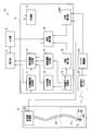
- the medical device 1 includes an endoscope apparatus 2, a main body unit 3 for performing insertion support, a display unit 4 that is a display unit, and an input unit 5 that is an input unit.
- the endoscopic apparatus 2 includes a bronchus having an insertion unit 2A that is an insertion unit in which an imaging unit 2B that is an imaging unit is disposed at a distal end portion 2C, and an endoscope control unit 2D that controls the insertion unit 2A and the like. It is a mirror.
- a channel 8 into which the treatment tool 6 can be inserted is disposed inside the insertion portion 2A.
- the main body unit 3 includes an endoscope image processing unit 11, a superimposed image generating unit 12 that is a superimposed image generating unit, a position calculating unit 20 that is a position calculating unit, and a virtual endoscopic image (Virtual Bronchus Scope image: hereinafter , Also referred to as a “VBS image”.)
- the control unit 10 controls the entire navigation.
- the endoscopic image processing unit 11 processes an image captured by the imaging unit 2B and outputs an endoscopic image (hereinafter also referred to as “real image”).
- the CT image data storage unit 15 stores three-dimensional image data of the subject 7 as a subject acquired in advance using a CT apparatus.
- the VBS image generation unit 13 generates a VBS image using the position, direction, and rotation angle (hereinafter also referred to as “position etc.”) of the distal end portion 2C as line-of-sight parameters from the three-dimensional image data.
- the position calculation unit 20 calculates the position and the like of the distal end portion 2C of the insertion portion 2A inserted into the bronchus 9.
- the core line calculation unit 16 calculates the core line S of the bronchi 9 from the three-dimensional image data.
- the core line S is a line connecting the barycentric points of the vertical direction of the bronchus 9, that is, information on the longitudinal direction of the lumen.
- information such as a center line that connects the center points of the vertical planes of the lumen in the duct direction may be used.
- the path generation unit 18 generates an insertion path R along the core line S from the three-dimensional image data to the target site 9G that is the target position set by the operator via the input unit 5.
- the tomographic image generation unit 14 generates a tomographic image PO that includes the three-dimensional position of the tip 2C calculated by the position calculator 20 and is perpendicular to the direction of the tip 2C from the three-dimensional image data.
- the superimposed image generation unit 12 is a superimposition that is a three-dimensional model image when a three-dimensional space in which the three-dimensional insertion path R and the tomographic image PO generated by the tomographic image generation unit 14 are superimposed is observed from a predetermined line of sight LA. An image PW1 is generated.
- the display unit 4 displays a navigation image having at least one of a real image and a VBS image and a superimposed image PW1 during the insertion operation.
- main body 3 do not have to be independent hardware, and may be programs that are read and operated by a CPU, for example.
- the tomographic image generated by the tomographic image generation unit 14 will be described with reference to FIGS. 3A to 3F.
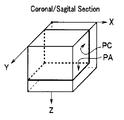
- the axial image PA shown in FIG. 3A is an image on the XY plane perpendicular to the body axis of the subject 7, and the coronal image PC shown in FIG. 3B is an image on the XZ plane facing the subject 7, FIG.
- the sagittal image PS shown in FIG. 3 is an image of the YZ plane in the side surface direction of the subject 7.
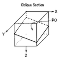
- the oblique image PO shown in FIG. 3D is an image of an arbitrary plane.
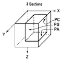
- the composite tomographic image shown in FIG. 3E is composed of two orthogonal planes PA and PC.
- the combined tomographic image including two orthogonal planes may be a combination of images of other planes. Further, it may be a composite tomographic image composed of the oblique image PO and an orthogonal plane image.
- the composite tomographic image shown in FIG. 3F is an example of a composite tomographic image including three orthogonal planes.
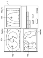
- ⁇ Setting operation mode >> First, the target position setting screen shown in FIG. An axial image PA, a coronal image PC, and a sagittal image PS are displayed on the target position setting screen.
- the target part 9G is set using the target position setting screen displayed on the display unit 4.
- the target position mark P9G indicating the target position is superimposed on the axial image PA, the coronal image PC, and the sagittal image PS displayed on the target position setting screen.
- the start position mark P7A indicating the position of the pharynx 7A, which is the insertion start position is within the display range of the axial image PA, but the display range of the coronal image PC and the sagittal image PS. Is outside.
- the target position mark P9G displayed on the other tomographic image also moves accordingly.
- the insertion start position may also be set by moving the start position mark P7A.
- the target position does not need to be a point and may be a target area having a predetermined volume. Further, in order to set the target position more accurately, the tomographic image may be enlarged and displayed.
- the path generation unit 18 calculates the insertion path R from the pharynx 7A, which is the insertion start position, to the target site 9G, which is the target position, by the CT image data storage unit. 15 is generated from the three-dimensional image data stored in 15.
- the insertion path R is a core line connected to the target site 9G among the core lines S connecting the center of gravity or the center point of the lumen cross section of the three-dimensional image data.
- the route generation unit 18 may generate a plurality of insertion routes and prompt the operator to select. That is, when the target site 9G exists between a plurality of lumens, or when the target site 9G is a site having a predetermined volume or more, a plurality of insertion paths are calculated.
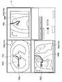
- a superimposed image PW2 in which a path image PPR indicating the insertion path R is superimposed on each tomographic image is displayed.
- the path image PPR is an image obtained by projecting the three-dimensional insertion path R onto the plane of each tomographic image.
- the VBS image generation unit 13 generates the VBS images of the branch units J1 to J4 in the insertion path R and the thumbnail images that are reduced images of the respective VBS images.
- FIG. 7 is an example of a navigation screen when the distal end portion 2C is at the first branch portion J1 of the four branch portions.
- the thumbnail image reduced images of the four branch portions J1 to J4 are displayed, and the branch portion number J1 is displayed larger.
- the position calculator 20 calculates the position and the like of the tip 2C in real time or at predetermined time intervals.
- the position calculation unit 20 controls the VBS image generation unit 13 to generate a VBS image similar to the real image captured by the CCD (2B). That is, the VBS image generation unit 13 generates a VBS image having the line-of-sight parameter as the position, direction, and rotation angle (X1, Y1, Z1, a1, e1, r1).
- (X, Y, Z) is a three-dimensional coordinate value
- (a) is an azimuth angle (azimuth angle)
- e) is an elevation angle (elevation angle)
- (r) is a rotation angle (roll angle).
- the position calculation unit 20 compares the similarity between the VBS image and the real image.
- the similarity between images is performed by known image processing, and either matching at the pixel data level or matching at the level of the feature extracted from the image may be used.
- the actual comparison process is performed based on the similarity between the static endoscope image and the VBS image.
- the position calculation unit 20 uses the line-of-sight parameter value with the changed value as the VBS image. Output to the generator 13.
- the VBS image generation unit 13 generates the next single VBS image according to the new line-of-sight parameter.
- the VBS image B generated by the VBS image generation unit 13 gradually becomes an image similar to a real image, and is repeated several times. Later, the error e between the two images is less than or equal to the allowable error e0.
- the position calculation unit 20 calculates information (X, Y, Z, a, e, r) such as the position of the tip 2C based on the line-of-sight parameter of the VBS image similar to the real image. That is, the position, direction, and rotation angle of the distal end portion 2C calculated by the position calculation unit 20 are more accurately the line-of-sight position, the line-of-sight direction, and the rotation angle of the imaging unit 2B disposed in the distal end portion 2C.
- the tomographic image generation unit 14 generates a tomographic image of the plane P including the three-dimensional position (X, Y, Z) of the distal end portion 2C calculated by the position calculation unit 20.
- the operator can select a desired image from the cross-sectional images shown in FIGS. 3A to 3E.
- a preferred tomographic image is the oblique image PO in a plane perpendicular to the direction of the distal end portion 2C shown in FIG. 3F, or a composite tomographic image including the oblique image PO. This is because the surgeon can most easily grasp the position and direction of the distal end portion 2C.
- the superimposed image generator 12 generates a superimposed image PW1 of the tomographic image PO and the insertion path R.
- the three-dimensional model image from the desired line of sight LA in the three-dimensional space in which the two-dimensional tomographic image PO and the three-dimensional insertion path R are arranged is superposed as shown in FIG. This is the image PW1.
- the path image is a two-dimensional path image obtained by projecting the three-dimensional insertion path R onto the tomographic image
- the tomographic image is a predetermined plane tomographic image. That is, the superimposed image PW2 is a normal two-dimensional image.
- the superimposed image PW1 is a three-dimensional model image, and can be changed to a desired state by the operator arbitrarily changing the line of sight LA.
- the line of sight LA is set on an extension of the plane of the tomographic image PO
- the tomographic image PO on the superimposed image PW1 is displayed as a line.
- the surgeon can obtain information on the tissue around the distal end portion 2C.
- the intersection of the path image PR indicating the insertion path R and the tomographic image PO is the position of the tip 2C, and a position display mark P2C is displayed.
- the superimposed image generation unit 12 displays the path image PR1 from the start position mark P7A indicating the position of the pharynx 7A, which is the insertion start position, to the position display mark P2C indicating the position of the tip 2C from the position display mark P2C.
- the path image PR2 up to the target position mark P9G indicating the target position is displayed with a distinguishable different line type. That is, the route image PR1 is displayed with a dotted line, and the route image PR2 is mainly displayed with a solid line.
- the superimposed image generation unit 12 displays a portion of the route image PR2 on the rear side of the tomographic image PO as viewed from the line of sight LA with a broken line.
- the superimposed image generation unit 12 may display the route image PR1 and the route image PR2 in different colors or thicknesses in order to identify them.
- the superimposed image generation unit 12 may not display the route image PR1.
- the superimposed image generation unit 12 may generate a superimposed image PW1A using a composite tomographic image as the tomographic image PO.
- the superimposed image PW1A is a three-dimensional model image of a combined tomographic image composed of two orthogonal planes PA and PC shown in FIG.
- the tip portion 7C is located on the intersection line between the plane PA and the plane PC perpendicular to the direction of the tip portion 7C.
- the superimposed image generation unit 12 may generate a superimposed image PW1B in which the branch portion display marks PJ1 to PJ4 indicating the positions of the respective branch portions are superimposed on the route image PR.
- the superimposed image generation unit 12 may generate a superimposed image PW1C in which the image PR2 of the core line S other than the insertion path is superimposed as the path image PR.
- display restrictions such as displaying only the core line S branched from the insertion path as shown in FIG.
- a display restriction method only a predetermined number of branch cores S may be displayed, or the core S may be displayed for a predetermined length from the branch part J.
- the superimposed image generation unit 12 may generate a superimposed image PW1D having an axial image PA including the position of the distal end portion 2C.
- the superimposed image generation unit 12 may display the tip end display mark P2CD indicating not only the position of the tip end 2C but also the direction of the tip end 2C on the superimposed image PW1D, or display only the direction. May be. That is, a predetermined effect can be obtained if the tip display mark indicates at least one of the position and direction of the tip.
- the superimposed image generation unit 12 may display the rotation angle of the tip 2C on the tip display mark.
- the superimposed image generation unit 12 does not display the route image PR1 of the path from the pharynx 7A to the tip 2C, which is the insertion path that has already passed, and thus the visibility of the superimposed image is good.
- the tomographic image generation unit 14 may generate a coronal image PC or a sagittal image PS including the position of the tip 2C.
- the tomographic image generation unit 14 generates a tomographic image based on the position and direction of the tip 2C, but can also generate a tomographic image based only on the position of the tip 2C.
- Step S16> Superimposed Display
- the superimposed image PW1 generated by the superimposed image generating unit 12 is displayed on the display unit 4 together with the real image and the VBS image.
- the superimposed image PW1 may be always displayed on the navigation screen, but the superimposed image PW1 may be temporarily hidden by the operator's setting, or automatically under the control of the control unit 10. The superimposed image PW1 may be hidden. Further, the type of tomographic image displayed on the superimposed image PW1 may be changed by the operator's setting or the control of the control unit 10.
- the image to be displayed on the navigation screen may be selected based on the position of the tip 2C. For example, when the distal end portion 2C approaches the branch portion J, the navigation mode including the superimposed image PW1 is displayed. The navigation screen does not display the superimposed image PW1 after the distal end portion 2C passes the branch portion J. The display mode may be switched to display.
- the switching of the display mode is controlled by the control unit 10 according to the presence or absence of a trigger setting, similarly to the switching of the navigation mode described later (see FIG. 24).
- the insertion navigation mode ends, the treatment tool 6 is projected from the distal end portion 2C, and a biopsy or the like of the target site 9G is performed.
- the medical device 1 allows the operator to easily grasp the position of the distal end portion 2 ⁇ / b> C from the superimposed image displayed on the display unit 4. Furthermore, the operator can grasp the state of the tissue near the distal end portion 2C from the tomographic image PO. For this reason, the medical device 1 can easily insert the distal end portion 2C of the insertion portion 2A up to the target site 9G.
- a medical device 1A according to a second embodiment of the present invention will be described with reference to the drawings. Since the medical device 1A is similar to the medical device 1, the same components are denoted by the same reference numerals and description thereof is omitted.
- the VBS image is not displayed on the navigation screen, and the second route image PR2 indicating the insertion route R is superimposed on the real image.
- the second route image PR2 In order to insert the second route image PR2 into the real image, first, the second route image PR2 to be superimposed on the VBS image corresponding to the real image is generated, and the generated second route image PR2 is real. It is superimposed on the image.
- the surgeon can perform the insertion operation while confirming the insertion path R with the second path image PR2 superimposed and displayed on the real image and grasping the position of the distal end portion 2C with the superimposed image PW1. .
- the medical device 1A has the effects of the medical device 1, and has a simple navigation screen and excellent visibility.
- Various configurations described in the medical device 1 can be used in the medical device 1 ⁇ / b> A, and the configuration of the medical device 1 ⁇ / b> A can be used in the medical device 1.
- the medical device 1B includes a display area calculation unit 30 that is a display area calculation unit.
- the display area calculation unit 30 calculates the display area of the second route PR2 superimposed and displayed on the VBS image.
- the insertion path R is calculated along the core S which is the center of the bronchus 9 having a predetermined thickness. For this reason, as shown to FIG. 16A, the 2nd path
- the superimposed image generation unit 12 highlights the second route image PR2. To do.
- the display area calculation unit 30 counts the number K of pixels of the second path image PR2 in the VBS image composed of 500 ⁇ 500 pixels. Then, when the number of pixels K is equal to or less than the first predetermined value K1, the superimposed image generation unit 12 displays a line for displaying the route image PR so that the number of pixels is K1, for example. That is, the shorter the route displayed in a superimposed manner, the thicker the route image PR is displayed.
- the real image may become partially white, or the color in the lumen and the color of the second route image PR2 may be difficult to distinguish. For this reason, as a highlighting method of the second route image PR2, the color or line type may be changed, or the blinking display may be performed.
- the display area calculation unit 30 calculates the average luminance for pixels in a range of a predetermined region of interest (ROI), not the entire real image RBS, and the second route image PR2 is changed according to the change in the average luminance.
- the display method may be changed so that the visibility is improved.
- the ROI is preferably set in a range surrounding the second route image PR2, and the shape may be any of a circle, an ellipse, a rectangle, a square, and the like. Further, the shape is not limited to a preset shape, and a graphic having a minimum area in the range surrounding the second route image PR2 may be selected for each process, or the second route image PR2 may be selected as a preselected shape. You may enlarge and reduce to the surrounding range.
- the medical device 1 ⁇ / b> C according to the second modification of the second embodiment includes an auxiliary insertion path generation unit 31 that is an auxiliary insertion path generation unit.
- the second route image PR2 may be displayed very short or not at all depending on the position or direction of the tip 2C. Then, it is not easy for the surgeon to recognize the correct insertion path.
- the superimposed image generation unit 12 when the display area of the second route image PR2 calculated by the display area calculation unit 30 is equal to or less than the second predetermined value K2, the superimposed image generation unit 12 The auxiliary insertion path image PSR is superimposed and displayed in place of the second path image PR2 or together with the second path image PR2.
- the second predetermined value K2 may be 0, for example.
- the auxiliary insertion path generation unit 31 uses not only the core information but also volume information as the three-dimensional shape information of the lumen.
- the core line S is a line connecting the center of gravity of the vertical direction of the lumen in the duct direction
- the volume is information indicating the position of the lumen wall.
- the auxiliary insertion path generation unit 31 generates an auxiliary insertion path SR that is a cross line between the plane including the insertion path R and the lumen wall of the bronchus 9 that is volume information.
- FIG. 19A shows a case where the lumen is a straight tube for the sake of explanation. For this reason, the plane including the insertion path R is a two-dimensional plane. However, since the actual lumen is curved, the plane including the insertion path R is also a curved plane.
- FIG. 19A shows a case where four auxiliary insertion paths SR are generated by two orthogonal surfaces including the insertion path R. For this reason, as shown in FIG. 19B, even when the core line S direction and the line-of-sight direction LA coincide, the four auxiliary insertion path images PSR are superimposed on the endoscopic image.
- auxiliary insertion path generation unit 31 may generate four or more, for example, eight auxiliary insertion paths SR.
- the medical devices 1B and 1C have the effects of the medical devices 1 and 1A, and are excellent in the visibility of the insertion path R on the navigation screen.
- Various configurations described in the medical devices 1 and 1A can be used in the medical devices 1B and 1C, and the configurations of the medical devices 1B and 1C can be used in the medical devices 1 and 1A.
- a medical device 1D according to a third embodiment of the present invention will be described with reference to the drawings. Since the medical device 1D is similar to the medical device 1, the same components are denoted by the same reference numerals and description thereof is omitted.
- a magnetic field sensor 21 that is a position sensor is disposed at the distal end portion 2C of the insertion portion 2A of the medical device 1D, and the position calculation unit 20D calculates the position of the distal end portion 2C from the data of the magnetic field sensor 21. The position, direction and rotation angle are calculated.
- the magnetic field sensor detects the magnetic field from the plurality of magnetic field generating antennas 22 disposed outside the subject 7, whereby the position calculation unit 20D detects the position of the tip 2C and the like. That is, since the arrangement position of the magnetic field sensor 21 arranged at the distal end portion 2C and the arrangement position of the imaging unit 2B are known, the position calculation unit 20D determines the line-of-sight position, the line-of-sight direction, and the rotation angle of the imaging unit 2B. Is detected.
- An MR sensor, a Hall element, a coil, or the like can be used as the magnetic field detection sensor.
- the medical device 1D has the same effect as the medical device 1.
- the various configurations described in the medical devices 1, 1A to 1C can be used, and the configuration of the medical device 1D can be used in the medical devices 1, 1A to 1C.
- a magnetic field sensor 21D which is a position sensor, is disposed at the distal end portion 6A of the treatment instrument 6 of the medical device 1DA.
- the position calculation unit 20D calculates the position, direction, and rotation angle of the tip 2C from the data of the magnetic field sensor 21D. Further, during the insertion operation of the treatment instrument 6, the position and direction and the rotation angle of the treatment instrument distal end portion 6A are calculated.
- the treatment tool tip 6A is the cutting edge when the treatment tool is a needle, but may be the center of the cup in the case of a biopsy forceps, and the center of the brush in the case of a brush. Also good.
- the magnetic field sensor 21D is an inductor. You may arrange
- the medical device 1DA has the same effect as the medical device 1D, and can acquire position information of the treatment instrument distal end portion 6A protruding from the channel opening 8E.
- a medical device 1E according to a fourth embodiment of the present invention will be described with reference to the drawings. Since the medical device 1E is similar to the medical device 1, the same components are denoted by the same reference numerals and description thereof is omitted.
- the tomographic image displayed on the navigation screen changes.
- the image displayed on the display unit 4 is selected by the control unit 10 based on the position of the distal end portion 2C. More specifically, when the distance between the position of the distal end portion 2C and the position of the target portion 9G is equal to or less than a predetermined value, or when the last branch portion is passed, the navigation mode is set to insert portion insertion.
- the support mode is switched to the treatment instrument operation support mode. Of course, the surgeon may select the navigation mode.
- an imaging unit 2B and an illumination unit 2B1 are disposed at the distal end portion 2C of the medical device 1E, and the treatment tool 6 can protrude from the channel opening 8E.
- the position of the channel opening 8E is different from the position of the imaging unit 2B.
- the medical device 1E preferably uses the position of the channel opening 8E as the position of the distal end portion 2C.
- the tomographic image generation unit 14 generates a tomographic image PPE including the position of the channel opening 8E and a plane parallel to the axial direction of the channel 8, that is, a plane parallel to the direction of the distal end portion 2C. Further, as shown in FIG. 23, the superimposed image generation unit 12 generates a superimposed image PW1E in which the extension line P8S of the channel 8 is superimposed and displayed on the tomographic image PPE.
- the extension line 8S indicates the direction in which the treatment tool 6 protrudes from the channel opening 8E.
- the scale may be added to the extension line P8S, or the color may be changed according to the length. Further, the direction of the extension line P8S may have a predetermined angle with respect to the direction of the distal end portion 2C, and the angle can be arbitrarily changed by the operator.
- Steps S20 to S23> This is the same as steps S10 to S13 of the medical device 1 of the first embodiment described with reference to FIG.
- a trigger is set by the control unit 10 according to the position of the distal end portion 2C calculated in S21.
- the trigger is set when the distance between the position of the distal end portion 2C and the target site 9G is equal to or less than a predetermined value.
- the distance between the position of the tip 2C and the target site 9G may be a linear distance or an insertion path distance via the core wire S.
- the trigger has a predetermined difference between the inner diameter of the bronchus 9 at the position of the distal end 2C or a predetermined value or a difference between the inner diameter of the bronchus 9 at the position of the distal end 2C and the outer diameter of the insertion part 2A. Set when the value falls below the value.
- the trigger may be set not only automatically by the control unit 10 but also by a setting operation via the operator's input unit 5.
- the trigger may be set by detecting that the image of the treatment tool 6 is reflected in the real image, that is, that the surgeon protrudes the treatment tool 6 from the channel opening 8E and starts biopsy.
- the treatment tool 6 protrudes from the channel opening 8E, the luminance of pixels in a range of a predetermined region of interest (ROI) of the real image increases. For this reason, an average luminance may be calculated for the ROI, and a trigger may be set according to a change in the average luminance.
- ROI region of interest
- Steps S27 to S30> This is the same as steps S14 to S17 of the medical device 1 according to the first embodiment described with reference to FIG.
- the medical device 1E has the same effect as the medical device 1 and the like, and further performs treatment tool operation support after the distal end portion 2C is inserted to the vicinity of the target site 9G.
- the various configurations described in the medical devices 1, 1A to 1D can be used, and the configuration of the medical device 1E can be used in the medical devices 1, 1A to 1D.
- a medical device 1F according to a fifth embodiment of the present invention will be described with reference to the drawings. Since the medical device 1F is similar to the medical device 1, the same components are denoted by the same reference numerals and description thereof is omitted.
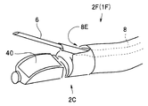
- the endoscope apparatus 2F of the medical device 1F has a convex scanning type ultrasonic transducer 40 for scanning an arcuate range at the distal end portion 2C.
- the operator can confirm the position of the lymph node or blood vessel by the ultrasonic image.
- the tomographic image generation unit 14 switches the navigation mode to the treatment instrument operation support mode, includes the position of the distal end portion 2C, and scans the ultrasonic transducer 40.
- a planar tomographic image PPF (see FIG. 26) is generated.
- the superimposed image generation unit 12 can treat the tomographic image PPF with the scanning range 41 of the ultrasonic transducer 40 and the treatment instrument 6 protruding from the channel opening 8E.
- a superimposed image PW1F in which the range 6E is displayed in a superimposed manner is generated.
- the surgeon can grasp the three-dimensional relationship between the scanning range 41 and the treatable range 6E by changing the line-of-sight position of the superimposed image PW1F, which is a three-dimensional model image.
- the navigation mode is switched by detecting the trigger setting as in the medical device 1E of the fourth embodiment.
- the medical device 1F has the same effect as the medical device 1 and the like, and further performs operation tool operation support after the distal end portion 2C is inserted to the vicinity of the target site 9G.
- the various configurations described in the medical devices 1, 1A to 1E can be used, and the configuration of the medical device 1F can be used in the medical devices 1, 1A to 1E.
- the medical device of the embodiment can also be used when observing the whole without determining the target site as in screening.
- the locus of the endoscope tip is displayed instead of the insertion path.
- the point constituting the trajectory may be a position obtained by the position calculating means, or a point on the center line of the luminal organ in the vicinity of the obtained position.
- the trajectory to be displayed may be a movement history indicating all movements of the endoscope tip so far, or may be only a trajectory within a predetermined period or a predetermined space range.
- by displaying the center line of the luminal organ superimposed on the trajectory it is easy to determine which part has been observed.
- a trajectory indicating all movement of the endoscope tip up to that point is displayed. Also good.
- the line indicating the endoscope tip position deeper than the carina, that is, the trajectory can be discriminated by displaying it in a different color or by displaying it with a dotted line.
Landscapes
- Health & Medical Sciences (AREA)
- Life Sciences & Earth Sciences (AREA)
- Surgery (AREA)
- Engineering & Computer Science (AREA)
- Animal Behavior & Ethology (AREA)
- Veterinary Medicine (AREA)
- Biomedical Technology (AREA)
- Heart & Thoracic Surgery (AREA)
- Medical Informatics (AREA)
- Molecular Biology (AREA)
- Nuclear Medicine, Radiotherapy & Molecular Imaging (AREA)
- General Health & Medical Sciences (AREA)
- Public Health (AREA)
- Robotics (AREA)
- Physics & Mathematics (AREA)
- Biophysics (AREA)
- Optics & Photonics (AREA)
- Pathology (AREA)
- Radiology & Medical Imaging (AREA)
- Apparatus For Radiation Diagnosis (AREA)
- Endoscopes (AREA)
- Ultra Sonic Daignosis Equipment (AREA)
Abstract
医療機器1は、被検者7の気管支9に挿入される挿入部と、予め取得した被検者7の3次元画像データを記憶するCT画像データ記憶部15と、気管支内における挿入部2Aの先端部2Cの位置および方向を算出する位置算出部20と、3次元画像に基づいて気管支9を介して先端部2Cを目標部位9Gまで挿入するための挿入経路Rを生成する経路生成部18と、先端部2Cの位置および方向に基づいた断層画像を3次元画像データから生成する断層画像生成部14と、挿入経路Rと断層画像POとを重畳した重畳画像PW1を生成する重畳画像生成部12と、重畳画像PW1を表示する表示部4と、を具備する。
Description
本発明の実施形態は、被検体の管腔に挿入する医療機器に関し、特に被検体の3次元画像データに基づき、精度の高い検査/処置を行う医療機器に関する。
近年、3次元画像を用いた診断が広く行われるようになっている。例えば、X線CT(Computed Tomography)装置により被検体の断層像を撮像することにより被検体内の3次元画像データを得て、この3次元画像データを用いて目標部位の診断が行われるようになっている。
CT装置では、X線照射位置および検出位置を連続的に回転させつつ、被検体を連続的に移動することにより、被検体を螺旋状の連続スキャン(ヘリカルスキャン:helical scan)する。そして、連続した被検体の多数の2次元断層画像から、3次元画像が形成される。
診断に用いられる3次元画像の1つに、肺の気管支の3次元画像がある。気管支の3次元画像は、例えば肺癌等が疑われる異常部の位置を3次元的に把握するのに利用される。そして、異常部を生検によって確認するために、気管支内視鏡を挿入して挿入部の先端部から生検針または生検鉗子等を突出して組織のサンプルを採取することが行われる。
気管支のように、多段階の分岐を有する体内の管路では、異常部の所在が気管支の末梢にあるときには、先端部を短時間で正しく目標部位近傍に到達させることが難しい。このため、例えば、日本国特開2004-180940号公報および日本国特開2005-131042号公報には、被検体の3次元の画像データに、基づいて前記被検体内の管路の3次元画像を形成し、3次元画像上で管路に沿って目的点までの経路を求め、経路に沿った前記管路の仮想内視画像を前記画像データに基づいて形成し、表示する挿入ナビゲーションシステムが開示されている。
また、日本国特開2003-265408号公報には、内視鏡先端部の位置を断層画像に重畳表示する内視鏡誘導装置が開示されている。
しかし、公知の挿入ナビゲーションシステムでは、術者が、挿入操作中に、挿入経路の全体像を確認することは容易ではないことがあった。また内視鏡先端部の位置を断層画像に重畳表示する場合であっても、3次元的な位置を確認するには2枚以上の断層画像を用いる必要があり、視認性がよいとはいえなかった。
このため、公知の挿入ナビゲーションシステムは、挿入部の先端部を目標部位まで容易に挿入できないことがあった。
本発明の実施形態は、挿入部の先端部を目標部位まで挿入しやすい医療機器を提供することを目的とする。
本発明の一の形態の医療機器は、被検体の管腔に挿入される挿入手段と、予め取得した前記被検体の3次元画像データを記憶する記憶手段と、前記管腔内における前記挿入手段の先端部の位置および方向を算出する位置算出手段と、前記3次元画像に基づいて、前記管腔を介して前記先端部を目標位置まで挿入するための挿入経路を生成する経路生成手段と、前記先端部の位置および方向に基づいた断層画像を、前記3次元画像データから生成する断層画像生成手段と、前記挿入経路と前記断層画像とを重畳した重畳画像を生成する重畳画像生成手段と、前記重畳画像を表示する表示手段と、を具備する。
<第1実施形態>
以下、図面を参照して本発明の第1実施形態の医療機器1について説明する。図1に示すように、医療機器1は、内視鏡装置2の挿入部2Aの先端部2Cを、挿入開始位置である被検者7の咽頭部7Aから、複数の分岐部J1~J5を有する気管支9を介して、目標位置である目標部位9Gまで挿入するナビゲーションを行う。図1は、目標部位9Gに向けて挿入部2Aが挿入操作されている状態を示している3次元モデル図である。挿入部2Aは、内部を挿通するチャンネル8を有し、チャンネル挿入口8Aから挿入された処置具6を、先端部2Cから突出させて、目標部位9Gの生検を行う。なお、以下の図において、Z軸方向は被検者7の体軸であり、X軸方向は被検者7の左右方向、Y軸方向は被検者7の前後方向である。
以下、図面を参照して本発明の第1実施形態の医療機器1について説明する。図1に示すように、医療機器1は、内視鏡装置2の挿入部2Aの先端部2Cを、挿入開始位置である被検者7の咽頭部7Aから、複数の分岐部J1~J5を有する気管支9を介して、目標位置である目標部位9Gまで挿入するナビゲーションを行う。図1は、目標部位9Gに向けて挿入部2Aが挿入操作されている状態を示している3次元モデル図である。挿入部2Aは、内部を挿通するチャンネル8を有し、チャンネル挿入口8Aから挿入された処置具6を、先端部2Cから突出させて、目標部位9Gの生検を行う。なお、以下の図において、Z軸方向は被検者7の体軸であり、X軸方向は被検者7の左右方向、Y軸方向は被検者7の前後方向である。
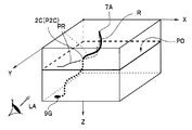
後述するように、医療機器1では、挿入操作中に、そのときの先端部2Cの位置を含み、先端部2Cの方向に垂直な平面の断層画像(オブリーク画像)POと、3次元の挿入経路Rと、が重畳表示された3次元空間を示す3次元モデル画像である重畳画像PW1が、表示部4(図2参照)に表示される。3次元モデル図の視線LA(視点位置、視線方向、視線回転角)は、術者が任意に設定可能である。
先端部2Cの位置変化につれて、すなわち挿入操作の進行につれて表示される断層画像POは自動的に更新される。なお、挿入部2Aの先端部2Cの位置を示す位置表示マークP2Cが、断層画像POに重畳表示されている。
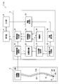
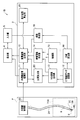
次に、図2を用いて、医療機器1の構成について説明する。医療機器1は、内視鏡装置2と、挿入支援を行うための本体部3と、表示手段である表示部4と、入力手段である入力部5と、を具備する。
内視鏡装置2は、撮像手段である撮像部2Bが先端部2Cに配設された挿入手段である挿入部2Aと、挿入部2A等を制御する内視鏡制御部2Dと、を有する気管支鏡である。挿入部2Aの内部には、処置具6が挿通可能なチャンネル8が配設されている。目標部位9Gの近傍まで先端部2Cが挿入されると、先端部2Cのチャンネル開口8Eから処置具6を突出させて生検が行われる。
本体部3は、内視鏡画像処理部11と、重畳画像生成手段である重畳画像生成部12と、位置算出手段である位置算出部20と、仮想内視鏡画像( Virtual Bronchus Scope 画像:以下、「VBS画像」ともいう。)生成部13と、断層画像生成手段である断層画像生成部14と、記憶手段であるCT画像データ記憶部15と、芯線算出手段である芯線算出部16と、経路生成手段である経路生成部18と、制御手段である制御部10と、を有する。
制御部10はナビゲーション全体の制御を行う。内視鏡画像処理部11は、撮像部2Bが撮像した画像を処理し、内視鏡画像(以下、「リアル画像」ともいう。)を出力する。CT画像データ記憶部15は、CT装置を用いて予め取得された被検体である被検者7の3次元画像データを記憶する。VBS画像生成部13は、3次元画像データから、先端部2Cの位置および方向および回転角(以下「位置等」ともいう)を視線パラメータとするVBS画像を生成する。
位置算出部20は、気管支9に挿入された挿入部2Aの先端部2Cの位置等を算出する。芯線算出部16は気管支9の芯線Sを、3次元画像データから算出する。ここで、芯線Sとは気管支9の管路方向垂直面の重心点を結んだ線、すなわち、管腔長手方向の情報である。芯線Sとして、管腔の管路方向垂直面の中心点を結んだ中心線等の情報を用いてもよい。
経路生成部18は、入力部5を介して術者が設定した目標位置である目標部位9Gまでの芯線Sに沿った挿入経路Rを、3次元画像データから生成する。
断層画像生成部14は、位置算出部20が算出した先端部2Cの3次元位置を含み、先端部2Cの方向に垂直な平面の断層画像POを、3次元画像データから生成する。
重畳画像生成部12は、3次元の挿入経路Rと断層画像生成部14が生成した断層画像POとを重畳した3次元空間を、所定の視線LAから観察したときの3次元モデル画像である重畳画像PW1を生成する。
表示部4は、挿入操作中は、リアル画像またはVBS画像の少なくともいずれかと、重畳画像PW1と、を有するナビゲーション画像を表示する。
なお、本体部3の上記構成要素は独立したハードウエアである必要はなく、例えばCPUに読み込まれて動作するプログラムであってもよい。
ここで、図3A~図3Fを用いて断層画像生成部14が生成する断層画像について説明する。
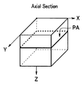
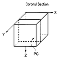
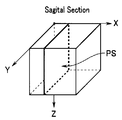
図3Aに示すアキシャル画像PAは、被検者7の体軸に垂直なXY面の画像であり、図3Bに示すコロナル画像PCは、被検者7と向かい合うXZ面の画像であり、図3Cに示すサジタル画像PSは、被検者7の側面方向のYZ面の画像である。そして、図3Dに示すオブリーク画像POは、任意の平面の画像である。
また、図3Eに示す複合断層画像は、2つの直交する平面PAとPCとからなる。直交する2つの平面を含む複合断層画像としては、他の平面の画像の組み合わせでもよい。さらに、前記オブリーク画像POおよび直交する平面の画像からなる複合断層画像であってもよい。また、図3Fに示す複合断層画像は、直交する3つの平面を含む複合断層画像の例である。
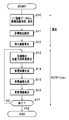
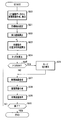
次に、図4のフローチャートを用いて、医療機器1の処理の流れについて説明する。
<<設定操作モード>>
最初に、図5に示す目標位置設定画面が表示部4に表示される。目標位置設定画面には、アキシャル画像PAとコロナル画像PCとサジタル画像PSとが表示されている。
最初に、図5に示す目標位置設定画面が表示部4に表示される。目標位置設定画面には、アキシャル画像PAとコロナル画像PCとサジタル画像PSとが表示されている。
<ステップS10> 断層画像作成
2次元画像を表示する表示部4を用いて、目標部位9Gを示す3次元座標を設定する必要があるため、最初に、3種類の断層画像、アキシャル画像PAとコロナル画像PCとサジタル画像PSと、が、被検者の3次元画像データから生成される。目標位置設定のための断層画像は、例えば体軸をZ軸として作成される。
2次元画像を表示する表示部4を用いて、目標部位9Gを示す3次元座標を設定する必要があるため、最初に、3種類の断層画像、アキシャル画像PAとコロナル画像PCとサジタル画像PSと、が、被検者の3次元画像データから生成される。目標位置設定のための断層画像は、例えば体軸をZ軸として作成される。
<ステップS11> 目標位置設定
図5に示すように、表示部4に表示された目標位置設定画面を用いて目標部位9Gが設定される。このために、目標位置設定画面に表示された、アキシャル画像PAとコロナル画像PCとサジタル画像PSには、目標位置を示す目標位置マークP9Gと、が重畳されている。なお、図5に示した例では、挿入開始位置である咽頭部7Aの位置を示す開始位置マークP7Aは、アキシャル画像PAの表示範囲内にはあるが、コロナル画像PC、サジタル画像PSの表示範囲外にある。
図5に示すように、表示部4に表示された目標位置設定画面を用いて目標部位9Gが設定される。このために、目標位置設定画面に表示された、アキシャル画像PAとコロナル画像PCとサジタル画像PSには、目標位置を示す目標位置マークP9Gと、が重畳されている。なお、図5に示した例では、挿入開始位置である咽頭部7Aの位置を示す開始位置マークP7Aは、アキシャル画像PAの表示範囲内にはあるが、コロナル画像PC、サジタル画像PSの表示範囲外にある。
術者が、いずれかの断層画像に重畳表示された目標位置マークP9Gを、入力手段であるマウス等を用いて移動すると、他の断層画像に表示された目標位置マークP9Gも、それにつれて移動する。
なお、挿入開始位置も開始位置マークP7Aの移動操作により設定可能であってもよい。また、目標位置は点である必要はなく所定の体積を有する目標領域であってもよい。また、より正確に目標位置を設定するために、断層画像を拡大表示してもよい。
<ステップS12> 挿入経路算出
目標部位9Gが設定されると、経路生成部18が、挿入開始位置である咽頭部7Aから目標位置である目標部位9Gまでの挿入経路Rを、CT画像データ記憶部15に記憶されている3次元画像データから生成する。挿入経路Rは、3次元画像データの管腔断面の重心点または中心点をつないだ芯線Sのうち、目標部位9Gにつながる芯線である。
目標部位9Gが設定されると、経路生成部18が、挿入開始位置である咽頭部7Aから目標位置である目標部位9Gまでの挿入経路Rを、CT画像データ記憶部15に記憶されている3次元画像データから生成する。挿入経路Rは、3次元画像データの管腔断面の重心点または中心点をつないだ芯線Sのうち、目標部位9Gにつながる芯線である。
経路生成部18は、複数の挿入経路を生成し、術者に選択を促してもよい。すなわち、目標部位9Gが複数の管腔の間に存在する場合、または、目標部位9Gが所定以上の体積を有する部位の場合等には、複数の挿入経路が算出される。
図6に示すように、挿入経路Rが算出されると、挿入経路Rを示す経路画像PPRが、それぞれの断層画像に重畳された重畳画像PW2が表示される。ここで経路画像PPRは、3次元の挿入経路Rを、それぞれの断層画像の平面に投影した画像である。
一方、VBS画像生成部13は、挿入経路Rにある分岐部J1~J4のVBS画像と、それぞれのVBS画像の縮小画像であるサムネイル画像とを、生成する。
<<挿入ナビゲーションモード>>
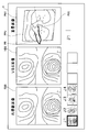
図7に示すように、挿入操作が開始されると、表示部4には、ナビゲーション画面が表示される。ナビゲーション画面には、リアル画像RBSと、VBS画像VBSと、重畳画像PW1と、サムネイル画像と、分岐番号と、が表示されている。なお、図7は、先端部2Cが、4個の分岐部のうちの最初の分岐部J1にあるときのナビゲーション画面例である。サムネイル画像には、4個の分岐部J1~J4の縮小画像が表示されており、分岐部番号J1が大きく表示されている。
図7に示すように、挿入操作が開始されると、表示部4には、ナビゲーション画面が表示される。ナビゲーション画面には、リアル画像RBSと、VBS画像VBSと、重畳画像PW1と、サムネイル画像と、分岐番号と、が表示されている。なお、図7は、先端部2Cが、4個の分岐部のうちの最初の分岐部J1にあるときのナビゲーション画面例である。サムネイル画像には、4個の分岐部J1~J4の縮小画像が表示されており、分岐部番号J1が大きく表示されている。
<ステップS13> 先端部の位置および方向および回転角算出
位置算出部20は、先端部2Cの位置等を、リアルタイムまたは所定の時間間隔で、算出する。
位置算出部20は、先端部2Cの位置等を、リアルタイムまたは所定の時間間隔で、算出する。
そして、位置算出部20は、VBS画像生成部13を制御して、CCD(2B)が撮影したリアル画像と類似したVBS画像を生成する。すなわち、VBS画像生成部13は、位置および方向および回転角(X1、Y1、Z1、a1、e1、r1)を視線パラメータとするVBS画像を生成する。ここで、(X、Y、Z)は3次元座標値を、(a)はアジマス角度(azimuth angle)を、(e)はエレベーション角度(elevation angle)を、(r)は回転角 (roll angle)を示している。
そして、位置算出部20は、VBS画像とリアル画像との類似度を比較する。ここで、画像の類似度は、公知の画像処理により行われ、画素データレベルのマッチング、または、画像から抽出した特徴のレベルにおけるマッチングのいずれを用いてもよい。
リアル画像とVBS画像とのマッチング処理は、リアル画像のフレーム単位で行われるため、実際の比較処理は静止内視鏡画像とVBS画像の類似度を基準に行われる。
リアル画像とVBS画像Bとの類似度を比較し算出した両画像の誤差eが、所定の許容誤差e0よりも大きい場合には、位置算出部20は、値を変えた視線パラメータ値をVBS画像生成部13に出力する。VBS画像生成部13は新規な視線パラメータに従った、次の1枚のVBS画像を生成する。
上記処理を繰り返し行うこと、すなわち、視線パラメータを変化させることで、VBS画像生成部13が生成するVBS画像Bは、徐々にリアル画像に類似した画像となっていき、何回かの繰り返し処理の後に、両画像の誤差eは、許容誤差e0以下となる。
そして、位置算出部20は、リアル画像と類似したVBS画像の視線パラメータをもとに、先端部2Cの位置等の情報(X、Y、Z、a、e、r)を算出する。すなわち、位置算出部20が算出する先端部2Cの位置および方向および回転角は、より正確には、先端部2Cに配設されている撮像部2Bの視線位置および視線方向および回転角である。
<ステップS14> 断層画像生成
断層画像生成部14は、位置算出部20が算出した先端部2Cの3次元位置(X、Y、Z)を含む平面Pの断層画像を生成する。なお、術者は、図3A~図3Eに示した断面画像の中から所望の画像を選択することができる。好ましい断層画像は、図3Fに示した、先端部2Cの方向と垂直な平面のオブリーク画像PO、または、前記オブリーク画像POを含む複合断層画像である。術者が先端部2Cの位置および方向を最も容易に把握できるためである。
断層画像生成部14は、位置算出部20が算出した先端部2Cの3次元位置(X、Y、Z)を含む平面Pの断層画像を生成する。なお、術者は、図3A~図3Eに示した断面画像の中から所望の画像を選択することができる。好ましい断層画像は、図3Fに示した、先端部2Cの方向と垂直な平面のオブリーク画像PO、または、前記オブリーク画像POを含む複合断層画像である。術者が先端部2Cの位置および方向を最も容易に把握できるためである。
<ステップS15> 重畳画像生成
重畳画像生成部12が、断層画像POと挿入経路Rとの重畳画像PW1を生成する。
重畳画像生成部12が、断層画像POと挿入経路Rとの重畳画像PW1を生成する。
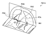
図8に示すように、2次元の断層画像POと、3次元の挿入経路Rと、が配置されている3次元空間の、所望の視線LAからの3次元モデル画像が、図9に示す重畳画像PW1である。
図9に示す重畳画像PW1は、図6に示した目標位置設定画面の重畳画像PW2と類似しているようにも見える。しかし、重畳画像PW2では、経路画像は、3次元の挿入経路Rを断層画像に投影した2次元の経路画像であり、また断層画像は予め定められた平面の断層像である。すなわち、重畳画像PW2は、通常の2次元画像である。
これに対して、重畳画像PW1は、3次元モデル画像であり、術者が視線LAを任意に変更することにより、所望の状態に変えることができる。例えば、視線LAを断層画像POの平面の延長上に設定すれば、重畳画像PW1上の断層画像POは、線で表示される。また、重畳画像PW1では断層画像POは先端部2Cを含むため、術者は先端部2Cの周囲組織の情報を得ることができる。
なお、重畳画像PW1においては、挿入経路Rを示す経路画像PRと断層画像POとの交点が、先端部2Cの位置であり、位置表示マークP2Cが表示されている。
また、重畳画像生成部12は、挿入開始位置である咽頭部7Aの位置を示す開始位置マークP7Aから先端部2Cの位置を示す位置表示マークP2Cまでの経路画像PR1を、位置表示マークP2Cから前記目標位置を示す目標位置マークP9Gまでの経路画像PR2とは、識別可能な異なる線種で表示している。すなわち、経路画像PR1は点線で、経路画像PR2は主として実線で表示されている。さらに重畳画像生成部12は、経路画像PR2のうち、視線LAから見て断層画像POの後側にある部分は破線で表示している。
なお 重畳画像生成部12は、経路画像PR1と、経路画像PR2とを、識別するために、異なる色または太さで表示してもよい。また重畳画像生成部12は、経路画像PR1を表示しなくともよい。
さらに、図10に示すように、重畳画像生成部12は、断層画像POとして、複合断層画像を用いた重畳画像PW1Aを生成してもよい。重畳画像PW1Aは、図3Eに示した2つの直交する平面PAとPCとからなる複合断層画像と挿入経路Rとの3次元モデル画像である。重畳画像PW1Aでは、平面PAと先端部7Cの方向と垂直な平面PCとの交差線上に先端部7Cがある。
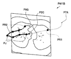
また、図11に示すように、重畳画像生成部12は、経路画像PRに、それぞれの分岐部の位置を示す分岐部表示マークPJ1~PJ4も重畳した重畳画像PW1Bを生成してもよい。
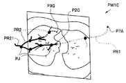
さらに、図12に示すように、重畳画像生成部12は、経路画像PRとして、挿入経路以外の芯線Sの画像PR2を、重畳した重畳画像PW1Cを生成してもよい。ただし、多くの芯線Sを表示すると認識が困難となるために、図12に示すように、挿入経路から1分岐した芯線Sのみを表示する等の表示制限を行うことが好ましい。表示制限方法としては、所定数の分岐の芯線Sのみを表示したり、分岐部Jから所定の長さだけ芯線Sを表示したりしてもよい。
また、図13に示すように、重畳画像生成部12は、先端部2Cの位置を含むアキシャル画像PAを有する重畳画像PW1Dを生成してもよい。この場合には、重畳画像生成部12は、重畳画像PW1Dに、先端部2Cの位置だけでなく先端部2Cの方向も示す先端部表示マークP2CDを表示してもよいし、方向のみを表示してもよい。すなわち、先端部表示マークは、先端部の位置または方向の少なくともいずれかを示していれば所定の効果が得られる。さらに重畳画像生成部12は、先端部表示マークに先端部2Cの回転角を表示してもよい。
なお、図13においては、重畳画像生成部12は、すでに通過した挿入経路である、咽頭部7Aから先端部2Cの経路の経路画像PR1を表示していないため、重畳画像の視認性がよい。
また、断層画像生成部14が、先端部2Cの位置を含む、コロナル画像PCまたはサジタル画像PSを生成してもよい。
すなわち、断層画像生成部14は、先端部2Cの位置および方向に基づいた断層画像を生成するが、先端部2Cの位置のみに基づく断層画像も生成可能である。
<ステップS16> 重畳表示
重畳画像生成部12が生成した重畳画像PW1が、リアル画像およびVBS画像とともに、表示部4に表示される。
重畳画像生成部12が生成した重畳画像PW1が、リアル画像およびVBS画像とともに、表示部4に表示される。
なお、重畳画像PW1は、常時、ナビゲーション画面に表示されていてもよいが、術者の設定により重畳画像PW1を一時的に非表示としてもよいし、制御部10の制御のもと、自動的に重畳画像PW1を非表示としてもよい。また、重畳画像PW1に表示される断層画像の種類も術者の設定または制御部10の制御により変更されてもよい。
ナビゲーション画面に表示する画像は、先端部2Cの位置に基づいて選択されてもよい。例えば、先端部2Cが分岐部Jに近づいたときは、重畳画像PW1を含むナビゲーション画面を表示する表示モードとし、先端部2Cが分岐部Jを通過した後は、重畳画像PW1を表示しないナビゲーション画面を表示する表示モードに切り替えてもよい。
表示モードの切り替えは、後述するナビゲーションモードの切り替えと同様に、トリガ設定の有無により制御部10が制御する(図24参照)。
<ステップS17> 終了?
目標部位9Gの近傍まで先端部2Cが挿入される(S17:Yes)まで、ステップS13からの処理が繰り返し行われる。
目標部位9Gの近傍まで先端部2Cが挿入される(S17:Yes)まで、ステップS13からの処理が繰り返し行われる。
目標部位9Gの近傍まで先端部2Cが挿入されると、挿入ナビゲーションモードは終了し、処置具6を、先端部2Cから突出させて、目標部位9Gの生検等が行われる。
以上の説明のように、医療機器1は、表示部4に表示される重畳画像により、術者が先端部2Cの位置を容易に把握できる。さらに術者は、先端部2Cの近傍組織の状態を断層画像POにより把握できる。このため医療機器1は、挿入部2Aの先端部2Cを目標部位9Gまで挿入しやすい。
<第2実施形態>
以下、図面を参照して本発明の第2実施形態の医療機器1Aについて説明する。医療機器1Aは、医療機器1と類似しているため、同じ構成要素には同じ符号を付し説明は省略する。
以下、図面を参照して本発明の第2実施形態の医療機器1Aについて説明する。医療機器1Aは、医療機器1と類似しているため、同じ構成要素には同じ符号を付し説明は省略する。
図14に示すように、医療機器1Aでは、ナビゲーション画面にVBS画像が表示されておらず、リアル画像には挿入経路Rを示す第2の経路画像PR2が重畳表示されている。
リアル画像に第2の経路画像PR2を挿入するためには、まずリアル画像と対応したVBS画像に重畳される第2の経路画像PR2が生成され、そして、生成した第2の経路画像PR2がリアル画像に重畳される。
術者は、リアル画像に重畳表示された第2の経路画像PR2により挿入経路Rを確認しながら、かつ、重畳画像PW1により先端部2Cの位置等を把握しながら、挿入操作を行うことができる。
医療機器1Aは、医療機器1が有する効果を有し、さらにナビゲーション画面が単純で視認性に優れている。なお、医療機器1Aにおいても医療機器1で説明した各種の構成を用いることができるし、医療機器1Aの構成を医療機器1で用いることもできる。
<第2実施形態の変形例1、2>
以下、図面を参照して本発明の第2実施形態の変形例1の医療機器1Bおよび変形例2の医療機器1Cについて説明する。医療機器1B、1Cは、医療機器1Aと類似しているため、同じ構成要素には同じ符号を付し説明は省略する。
以下、図面を参照して本発明の第2実施形態の変形例1の医療機器1Bおよび変形例2の医療機器1Cについて説明する。医療機器1B、1Cは、医療機器1Aと類似しているため、同じ構成要素には同じ符号を付し説明は省略する。
図15に示すように医療機器1Bは、表示面積算出手段である表示面積算出部30を具備する。表示面積算出部30は、VBS画像に重畳表示された第2の経路PR2の表示面積を算出する。
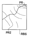
挿入経路Rは所定の太さのある気管支9の中心である芯線Sに沿って算出されている。このため、図16Aに示すように、VBS画像に表示される第2の経路は、先端部2Cの方向等によっては、短くなる。すると、術者が正しい挿入経路Rを認識することが容易ではなくなる。
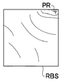
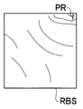
しかし、図16Bに示すように、医療機器1Aでは、表示面積算出部30が算出した表示面積が第1の所定値以下の場合に、重畳画像生成部12が第2の経路画像PR2を強調表示する。
例えば、表示面積算出部30は、500×500の画素で構成されているVBS画像の中の、第2の経路画像PR2の画素数Kをカウントする。そして、画素数Kが第1の所定値K1以下の場合に、重畳画像生成部12が経路画像PRを表示する線を、例えば、画素数がK1となるように太く表示する。すなわち、重畳表示される経路が短いほど、経路画像PRは太く表示される。
また、リアル画像はハレーション等を起こすと部分的に真っ白になってしまうこともあるし、管腔内の色と第2の経路画像PR2の色との区別がつきにくくなることもある。このため、第2の経路画像PR2の強調表示方法としては、色または線種を変えてもよいし、点滅表示するようにしてもよい。
また、表示面積算出部30は、リアル画像RBSの全体ではなく、所定の注目領域(ROI)の範囲の画素について平均輝度を算出し、その平均輝度の変化に応じて第2の経路画像PR2の視認性が改善するように表示方法を変更してもよい。
ROIとしては、第2の経路画像PR2を取り囲む範囲に設定することが好ましく、その形状は円、楕円、長方形、または正方形等のいずれであってもよい。また予め設定した形状に限られるものではなく、処理毎に第2の経路画像PR2を取り囲む範囲が最小面積となる図形を選択してもよいし、予め選択した図形を第2の経路画像PR2を取り囲む範囲に拡大縮小してもよい。
一方、図17に示すように、第2実施形態の変形例2の医療機器1Cは、補助挿入経路生成手段である補助挿入経路生成部31を有する。
図18Aに示すように、先端部2Cの位置または方向によっては、第2の経路画像PR2が極めて短く表示されたり、または全く表示されないこともある。すると、術者が正しい挿入経路を認識することが容易ではなくなる。
しかし、図18Bに示すように、医療機器1Bでは、表示面積算出部30が算出した第2の経路画像PR2の表示面積が第2の所定値K2以下の場合に、重畳画像生成部12が第2の経路画像PR2に変えて、または第2の経路画像PR2とともに補助挿入経路画像PSRを重畳表示する。ここで、第2の所定値K2は、例えば0であってもよい。
補助挿入経路生成部31は、管腔の3次元形状情報として、芯線情報だけでなく、ボリューム情報も用いる。すでに説明したように、芯線Sは管腔の管路方向垂直面の重心点を結んだ線であるが、ボリュームは管腔の管壁の位置を示す情報である。
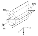
すなわち、図19Aに示すように、補助挿入経路生成部31は、挿入経路Rを含む面と、ボリューム情報である気管支9の管腔壁と、の交差線である、補助挿入経路SRを生成する。なお、図19Aは説明のため管腔が直管の場合を示している。このため、挿入経路Rを含む面は2次元の平面である。しかし、実際の管腔は湾曲しているため、挿入経路Rを含む面も湾曲した平面である。
図19Aは、挿入経路Rを含む直交した2つの面により、4本の補助挿入経路SRが生成される場合を示している。このため、図19Bに示すように芯線S方向と視線方向LAが一致する場合でも、内視鏡画像には、4本の補助挿入経路画像PSRが重畳される。
なお、補助挿入経路生成部31は、4本以上、例えば8本の補助挿入経路SRを生成してもよい。
医療機器1Bおよび1Cは、医療機器1、1Aが有する効果を有し、さらにナビゲーション画面における挿入経路Rの視認性に優れている。なお、医療機器1Bおよび1Cにおいても医療機器1、1Aで説明した各種の構成を用いることができるし、医療機器1B、1Cの構成を医療機器1、1Aで用いることもできる。
<第3実施形態>
以下、図面を参照して本発明の第3実施形態の医療機器1Dについて説明する。医療機器1Dは、医療機器1と類似しているため、同じ構成要素には同じ符号を付し説明は省略する。
以下、図面を参照して本発明の第3実施形態の医療機器1Dについて説明する。医療機器1Dは、医療機器1と類似しているため、同じ構成要素には同じ符号を付し説明は省略する。
図20に示すように、医療機器1Dの挿入部2Aの先端部2Cには位置センサである磁界センサ21が配設されており、位置算出部20Dは、磁界センサ21のデータから先端部2Cの位置および方向および回転角を算出する。
磁界センサが、被検者7の外部に配設した複数の磁界発生アンテナ22からの磁界を検出することで、位置算出部20Dは、先端部2Cの位置等を検出する。すなわち、先端部2Cに配設された磁界センサ21の配設位置と撮像部2Bの配設位置とは既知であるため、位置算出部20Dは、撮像部2Bの視線位置および視線方向および回転角を検出する。なお、磁界検出センサとして、MRセンサ、ホール素子またはコイル等を用いることができる。
医療機器1Dは、医療機器1と同じ効果を有する。なお、医療機器1Dにおいても医療機器1、1A~1Cで説明した各種の構成を用いることができるし、医療機器1Dの構成を医療機器1、1A~1Cで用いることもできる。
<第3実施形態の変形例>
以下、図面を参照して本発明の第3実施形態の変形例の医療機器1DAについて説明する。医療機器1DAは、医療機器1Dと類似しているため、同じ構成要素には同じ符号を付し説明は省略する。
以下、図面を参照して本発明の第3実施形態の変形例の医療機器1DAについて説明する。医療機器1DAは、医療機器1Dと類似しているため、同じ構成要素には同じ符号を付し説明は省略する。
図21に示すように、医療機器1DAの処置具6の処置具先端部6Aには位置センサである磁界センサ21Dが配設されている。そして、挿入部2Aの挿入操作中は、処置具先端部6Aは挿入部2Aの先端部2Cに収容されている。このため、位置算出部20Dは、磁界センサ21Dのデータから先端部2Cの位置および方向および回転角を算出する。さらに処置具6を挿入操作中は、処置具先端部6Aの位置および方向および回転角を算出する。なお、処置具先端部6Aとは、処置具が針の場合には刃先であるが、生検鉗子の場合にはカップの中心であってもよく、ブラシの場合にはブラシの中心であってもよい。
なお、気管支分岐への挿入を補助するために、処置具6として、先細り型で関節付きの先端部を手元操作で曲げられる鉗子である誘導子を用いる場合には、磁界センサ21Dは誘導子の先端部に配設されていてもよい。
医療機器1DAは医療機器1Dと同じ効果を有し、さらに、チャンネル開口8Eから突出した処置具先端部6Aの位置情報を取得することができる。
<第4実施形態>
以下、図面を参照して本発明の第4実施形態の医療機器1Eについて説明する。医療機器1Eは、医療機器1と類似しているため、同じ構成要素には同じ符号を付し説明は省略する。
以下、図面を参照して本発明の第4実施形態の医療機器1Eについて説明する。医療機器1Eは、医療機器1と類似しているため、同じ構成要素には同じ符号を付し説明は省略する。
医療機器1Eは、挿入部2Aの先端部2Cが、目標部位9Gの近傍まで到達すると、ナビゲーション画面に表示される断層画像が変化する。言い換えれば、表示部4が表示する画像が、先端部2Cの位置に基づいて制御部10により選択される。より具体的には、先端部2Cの位置と目標部位9Gの位置との距離が所定値以下となった場合、または、最後の分岐部を通過した場合等には、ナビゲーションモードが、挿入部挿入支援モードから、処置具操作支援モードに切り替わる。もちろん術者が、ナビゲーションモードを選択してもよい。
ここで、図22に示すように医療機器1Eの先端部2Cには、撮像部2B、照明部2B1が配設されており、チャンネル開口8Eからは処置具6が突出可能である。チャンネル開口8Eの位置と撮像部2Bの位置とは異なる。より正確な処置具操作支援を行うために、ナビゲーションモードが処置具操作支援モードに切り替わると、医療機器1Eでは、先端部2Cの位置としてチャンネル開口8Eの位置を用いることが好ましい。
そして、断層画像生成部14は、チャンネル開口8Eの位置を含み、チャンネル8の軸方向に平行な平面、すなわち先端部2Cの方向と平行な平面の断層画像PPEを生成する。さらに、図23に示すように、重畳画像生成部12は、断層画像PPEにチャンネル8の延長線P8Sを重畳表示した重畳画像PW1Eを生成する。延長線8Sは処置具6がチャンネル開口8Eから突出する方向を示している。
延長線P8Sには目盛りが付加されていたり、長さに応じて色が変えられたりしてもよい。また、延長線P8Sの方向は、先端部2Cの方向に対して所定の角度を有していてもよく、その角度は術者が任意に変更可能である。
ここで、図24のフローチャートを用いて、医療機器1Eにおけるナビゲーションモードの切り替えについて説明する。
<ステップS20~S23>
図4を用いて説明した第1実施形態の医療機器1のステップS10~S13と同様である。
図4を用いて説明した第1実施形態の医療機器1のステップS10~S13と同様である。
<ステップS24>トリガ算出
医療装置1Eでは、S21にて算出した先端部2Cの位置に応じてトリガが制御部10により設定される。例えば、トリガは、先端部2Cの位置と目標部位9Gとの距離が所定値以下になった場合に設定される。ここで、先端部2Cの位置と目標部位9Gとの距離は、直線距離でもよいし、芯線Sを介した挿入経路距離でもよい。
医療装置1Eでは、S21にて算出した先端部2Cの位置に応じてトリガが制御部10により設定される。例えば、トリガは、先端部2Cの位置と目標部位9Gとの距離が所定値以下になった場合に設定される。ここで、先端部2Cの位置と目標部位9Gとの距離は、直線距離でもよいし、芯線Sを介した挿入経路距離でもよい。
また、例えば、トリガは、先端部2Cの位置の気管支9の内径が所定値以下になった場合、または、先端部2Cの位置の気管支9の内径と挿入部2Aの外径との差が所定値以下になった場合に設定される。
また、トリガは制御部10により自動的に設定されるだけでなく、術者の入力部5を介した設定操作によって設定されてもよい。または、リアル画像に処置具6の画像が映ったこと、すなわち、術者がチャンネル開口8Eから処置具6を突出して生検を開始したことを検出してトリガを設定してもよい。
例えば、処置具6がチャンネル開口8Eから突出すると、リアル画像の所定の注目領域(ROI)の範囲の画素の輝度が上がる。このためROIについて平均輝度を算出し、その平均輝度の変化に応じてトリガを設定してもよい。
<ステップS25>トリガON?<ステップS26>モード切り替え
トリガがONの場合(YES)、ステップS26においてナビゲーションモードが切り替わる。これに対してトリガがOFFの場合(NO)、今までのナビゲーションモードが継続する。
トリガがONの場合(YES)、ステップS26においてナビゲーションモードが切り替わる。これに対してトリガがOFFの場合(NO)、今までのナビゲーションモードが継続する。
<ステップS27~S30>
図4を用いて説明した第1実施形態の医療機器1のステップS14~S17と同様である。
図4を用いて説明した第1実施形態の医療機器1のステップS14~S17と同様である。
医療機器1Eは、医療機器1等と同じ効果を有し、さらに先端部2Cが目標部位9Gの近傍まで挿入された後も、さらに処置具操作支援を行う。なお、医療機器1Eにおいても医療機器1、1A~1Dで説明した各種の構成を用いることができるし、医療機器1Eの構成を医療機器1、1A~1Dで用いることもできる。
<第5実施形態>
以下、図面を参照して本発明の第5実施形態の医療機器1Fについて説明する。医療機器1Fは、医療機器1と類似しているため、同じ構成要素には同じ符号を付し説明は省略する。
以下、図面を参照して本発明の第5実施形態の医療機器1Fについて説明する。医療機器1Fは、医療機器1と類似しているため、同じ構成要素には同じ符号を付し説明は省略する。
図24に示すように、医療機器1Fの内視鏡装置2Fは、円弧状の範囲を走査するコンベックス走査方式の超音波振動子40を先端部2Cに有している。術者は超音波画像によりリンパ節または血管等の位置を確認することができる。
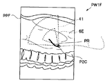
そして、断層画像生成部14は、先端部2Cが目標部位9Gの近傍まで挿入されると、ナビゲーションモードが処置具操作支援モードに切り替わり、先端部2Cの位置を含み、超音波振動子40の走査平面の断層画像PPF(図26参照)を生成する。
さらに、図25に示すように、処置具操作支援モードでは、重畳画像生成部12は、断層画像PPFに超音波振動子40の走査範囲41と、チャンネル開口8Eから突出した処置具6が処置可能な範囲6Eと、を重畳表示した重畳画像PW1Fを生成する。
術者は、3次元モデル画像である重畳画像PW1Fの、視線位置等を変更することで、走査範囲41と処置可能な範囲6Eとの3次元の関係を把握することができる。
なお、医療機器1Fにおいても、ナビゲーションモードの切り替えは、第4実施形態の医療機器1Eと同様に、トリガの設定を検出することにより行われる。
医療機器1Fは、医療機器1等と同じ効果を有し、さらに先端部2Cが目標部位9Gの近傍まで挿入された後も、さらに処置具操作支援を行う。なお、医療機器1Fにおいても医療機器1、1A~1Eで説明した各種の構成を用いることができるし、医療機器1Fの構成を医療機器1、1A~1Eで用いることもできる。
なお、実施形態の医療機器は、スクリーニングのように目的部位を確定しないで全体を観察するときにも使用できる。この場合には挿入経路に替えて内視鏡先端の軌跡を表示する。軌跡を構成する点は、位置算出手段で求めた位置でもよいし、求めた位置近傍にある管腔臓器の中心線上の点でもよい。また表示する軌跡は、それまでの内視鏡先端の全ての移動を示す移動履歴でもよいし、所定期間または所定空間範囲内の軌跡のみでもよい。また、軌跡に管腔臓器の中心線を重畳表示することにより、どの部位まで観察したのかの判別が容易となる。
スクリーニングのときには、所定の部位まで内視鏡先端を挿入後に、例えば、カリーナまで内視鏡を引き抜いたときにも、それまでの内視鏡先端の全ての移動を示す軌跡を表示しておいてもよい。そのときには、カリーナよりも深部側の内視鏡先端位置を示す線、すなわち軌跡は別色で表示したり点線で表示したりして判別可能とすることが好ましい。
すなわち、本発明は、上述した実施形態または変形例に限定されるものではなく、本発明の要旨を変えない範囲において、種々の変更、改変等が可能である。例えばすでに説明したように上述した実施形態および変形例は適宜、組み合わせてもよい。
本出願は、2011年1月24日に日本国に出願された特願2011-012103号を優先権主張の基礎として出願するものであり、上記の開示内容は、本願明細書、請求の範囲、図面に引用されたものとする。
Claims (17)
- 被検体の管腔に挿入される挿入手段と、
予め取得した前記被検体の3次元画像データを記憶する記憶手段と、
前記管腔内における前記挿入手段の先端部の位置および方向を算出する位置算出手段と、
前記3次元画像に基づいて、前記管腔を介して前記先端部を目標位置まで挿入するための挿入経路を生成する経路生成手段と、
前記先端部の位置および方向に基づいた断層画像を、前記3次元画像データから生成する断層画像生成手段と、
前記挿入経路と前記断層画像とを重畳した重畳画像を生成する重畳画像生成手段と、
前記重畳画像を表示する表示手段と、を具備することを特徴とする医療機器。 - 前記断層画像生成手段が、前記先端部の位置を含み、前記先端部の方向と垂直な平面の断層画像を生成することを特徴とする請求項1に記載の医療機器。
- 前記重畳画像生成手段が、前記重畳画像に、前記先端部の位置または方向の少なくともいずれかを示す先端部表示マークを、重畳することを特徴とする請求項1に記載の医療機器。
- 前記重畳画像生成手段が、前記挿入経路に、分岐している前記管路の分岐部の位置を示す分岐部表示マークを重畳することを特徴とする請求項1に記載の医療機器。
- 前記重畳画像生成手段が、挿入開始位置から前記先端部の位置までの前記挿入経路を、前記先端部の位置から前記目標位置までの前記挿入経路と、識別可能に表示することを特徴とする請求項1に記載の医療機器。
- 前記重畳画像生成手段が、挿入開始位置から前記先端部の位置までの前記挿入経路を表示しないことを特徴とする請求項1に記載の医療機器。
- 前記挿入手段が、前記先端部に内視鏡画像を撮像する撮像手段を有し、
前記先端部の位置および方向および回転角を視線パラメータとする仮想内視鏡画像を前記3次元画像データから生成する仮想内視鏡画像生成手段を具備し、
前記表示手段が、さらに前記内視鏡画像または前記仮想内視鏡画像の少なくともいずれかを表示することを特徴とする請求項1に記載の医療機器。 - 位置算出手段が、前記内視鏡画像と類似した前記仮想内視鏡画像の視線パラメータをもとに、前記先端部の位置および方向を算出することを特徴とする請求項7に記載の医療機器
- 前記重畳画像生成手段が、前記挿入経路を示す第2の挿入経路画像を前記内視鏡画像または前記仮想内視鏡画像の少なくともいずれかに重畳表示することを特徴とする請求項8に記載の医療機器。
- 重畳表示された前記第2の挿入経路画像の表示面積を算出する表示面積算出手段を具備し、
前記表示面積が第1の所定値以下の場合に、前記重畳画像生成手段が前記第2の挿入経路画像を強調表示することを特徴とする請求項9に記載の医療機器。 - 重畳表示された前記第2の挿入経路画像の表示面積を算出する表示面積算出手段と、
前記挿入経路を含む平面と前記管腔の管腔壁との交差線である、補助挿入経路を算出する補助挿入経路算出手段と、を具備し、
前記表示面積が第2の所定値以下の場合に、前記重畳画像生成手段が前記補助挿入経路を示す補助経路画像を重畳表示することを特徴とする請求項9に記載の医療機器。 - 前記先端部に配設された位置センサを具備し、
前記位置算出手段が、前記位置センサのデータから前記先端部の位置および方向を算出することを特徴とする請求項1に記載の医療機器。 - 前記先端部のチャンネル開口から突出する、処置具先端部に位置センサを有する処置具、を具備し、
前記位置算出手段が、前記位置センサのデータから前記先端部の位置および方向を算出することを特徴とする請求項1に記載の医療機器。 - 前記表示手段が表示する画像が、前記先端部の位置に基づいて選択されることを特徴とする請求項9に記載の医療機器。
- 前記断層画像生成手段が、前記先端部の位置を含み、前記先端部の方向と平行な平面の断層画像を、さらに生成することを特徴とする請求項14に記載の医療機器。
- 前記挿入手段が、内部を挿通し前記先端部にチャンネル開口のあるチャンネルを有し、
前記断層画像生成手段が、前記先端部の方向と平行な平面の前記断層画像を生成するときには、前記先端部の位置として前記チャンネル開口の位置に基づいて、前記断層画像を生成することを特徴とする請求項15に記載の医療機器。 - 前記挿入手段が、コンベックス走査方式の超音波振動子を前記先端部に有し、
前記断層画像生成手段が生成する前記先端部の方向と平行な平面の前記断層画像が、前記超音波振動子の走査平面の断層画像であることを特徴とする請求項16に記載の医療機器。
Priority Applications (4)
| Application Number | Priority Date | Filing Date | Title |
|---|---|---|---|
| JP2012533423A JP5160699B2 (ja) | 2011-01-24 | 2011-11-08 | 医療機器 |
| EP11857389.8A EP2581029B1 (en) | 2011-01-24 | 2011-11-08 | Medical device |
| CN201180038533.3A CN103068294B (zh) | 2011-01-24 | 2011-11-08 | 医疗设备 |
| US13/556,732 US20120287238A1 (en) | 2011-01-24 | 2012-07-24 | Medical device |
Applications Claiming Priority (2)
| Application Number | Priority Date | Filing Date | Title |
|---|---|---|---|
| JP2011-012103 | 2011-01-24 | ||
| JP2011012103 | 2011-01-24 |
Related Child Applications (1)
| Application Number | Title | Priority Date | Filing Date |
|---|---|---|---|
| US13/556,732 Continuation US20120287238A1 (en) | 2011-01-24 | 2012-07-24 | Medical device |
Publications (1)
| Publication Number | Publication Date |
|---|---|
| WO2012101888A1 true WO2012101888A1 (ja) | 2012-08-02 |
Family
ID=46580474
Family Applications (1)
| Application Number | Title | Priority Date | Filing Date |
|---|---|---|---|
| PCT/JP2011/075686 Ceased WO2012101888A1 (ja) | 2011-01-24 | 2011-11-08 | 医療機器 |
Country Status (5)
| Country | Link |
|---|---|
| US (1) | US20120287238A1 (ja) |
| EP (1) | EP2581029B1 (ja) |
| JP (1) | JP5160699B2 (ja) |
| CN (1) | CN103068294B (ja) |
| WO (1) | WO2012101888A1 (ja) |
Cited By (16)
| Publication number | Priority date | Publication date | Assignee | Title |
|---|---|---|---|---|
| WO2014024995A1 (ja) * | 2012-08-08 | 2014-02-13 | 株式会社東芝 | 医用画像診断装置、画像処理装置及び画像処理方法 |
| WO2014141968A1 (ja) * | 2013-03-12 | 2014-09-18 | オリンパスメディカルシステムズ株式会社 | 内視鏡システム |
| CN104755009A (zh) * | 2013-04-15 | 2015-07-01 | 奥林巴斯医疗株式会社 | 内窥镜系统 |
| JP2015198826A (ja) * | 2014-04-09 | 2015-11-12 | コニカミノルタ株式会社 | 超音波画像診断装置及び超音波画像表示方法 |
| EP2912987A4 (en) * | 2012-10-25 | 2016-07-06 | Olympus Corp | INSERTION SYSTEM, INSERTION ASSISTING DEVICE, INSERTION SUPPORT METHOD, AND PROGRAM |
| JP2016179121A (ja) * | 2015-03-25 | 2016-10-13 | 富士フイルム株式会社 | 内視鏡検査支援装置、方法およびプログラム |
| JP2016221095A (ja) * | 2015-06-02 | 2016-12-28 | 株式会社島津製作所 | 放射線透視装置 |
| JP2017055954A (ja) * | 2015-09-16 | 2017-03-23 | 富士フイルム株式会社 | 内視鏡位置特定装置、方法およびプログラム |
| JP2017093729A (ja) * | 2015-11-20 | 2017-06-01 | ザイオソフト株式会社 | 医用画像処理装置、医用画像処理方法、及び医用画像処理プログラム |
| JP2017525418A (ja) * | 2014-07-02 | 2017-09-07 | コヴィディエン リミテッド パートナーシップ | インテリジェントディスプレイ |
| JP2019042506A (ja) * | 2017-08-31 | 2019-03-22 | バイオセンス・ウエブスター・(イスラエル)・リミテッドBiosense Webster (Israel), Ltd. | 解剖学的画像における内視鏡の位置及び光軸の表示 |
| JPWO2020090729A1 (ja) * | 2018-11-01 | 2021-09-24 | 富士フイルム株式会社 | 医療画像処理装置、医療画像処理方法及びプログラム、診断支援装置 |
| WO2021192593A1 (ja) * | 2020-03-26 | 2021-09-30 | Hoya株式会社 | プログラム、情報処理方法、情報処理装置及び診断支援システム |
| JP2023018984A (ja) * | 2021-07-28 | 2023-02-09 | 株式会社エビデント | 挿入支援システム、挿入支援方法、およびプログラム |
| JP2023176613A (ja) * | 2022-05-31 | 2023-12-13 | 富士フイルム株式会社 | 情報処理装置、超音波内視鏡、情報処理方法、及びプログラム |
| JP2024540751A (ja) * | 2021-11-19 | 2024-11-01 | コーニンクレッカ フィリップス エヌ ヴェ | ロボット式脈管内デバイスのx線透視フィードバックによる制御 |
Families Citing this family (58)
| Publication number | Priority date | Publication date | Assignee | Title |
|---|---|---|---|---|
| WO2013111813A1 (ja) * | 2012-01-27 | 2013-08-01 | 株式会社 東芝 | 医用画像処理装置 |
| EP2904957A4 (en) * | 2013-03-06 | 2016-08-24 | Olympus Corp | ENDOSCOPE SYSTEM |
| US9639666B2 (en) | 2013-03-15 | 2017-05-02 | Covidien Lp | Pathway planning system and method |
| US9925009B2 (en) | 2013-03-15 | 2018-03-27 | Covidien Lp | Pathway planning system and method |
| US9459770B2 (en) | 2013-03-15 | 2016-10-04 | Covidien Lp | Pathway planning system and method |
| CN103169445B (zh) * | 2013-04-16 | 2016-07-06 | 苏州朗开医疗技术有限公司 | 一种内窥镜的导航方法及系统 |
| KR101466153B1 (ko) * | 2013-05-02 | 2014-11-27 | 삼성메디슨 주식회사 | 의료 영상 장치 및 그 제어 방법 |
| EP2926714A4 (en) * | 2013-06-18 | 2016-07-13 | Olympus Corp | ENDOSCOPE SYSTEM AND METHOD OF CONTROLLING ENDOSCOPE SYSTEM |
| WO2015049962A1 (ja) * | 2013-10-02 | 2015-04-09 | オリンパスメディカルシステムズ株式会社 | 内視鏡システム |
| US10772684B2 (en) * | 2014-02-11 | 2020-09-15 | Koninklijke Philips N.V. | Spatial visualization of internal mammary artery during minimally invasive bypass surgery |
| CN106102549B (zh) * | 2014-03-17 | 2018-12-04 | 直观外科手术操作公司 | 用于控制成像器械定向的系统和方法 |
| US9603668B2 (en) | 2014-07-02 | 2017-03-28 | Covidien Lp | Dynamic 3D lung map view for tool navigation inside the lung |
| US9530219B2 (en) | 2014-07-02 | 2016-12-27 | Covidien Lp | System and method for detecting trachea |
| CN106659453B (zh) | 2014-07-02 | 2020-05-26 | 柯惠有限合伙公司 | 用于分割肺部的系统和方法 |
| US9754367B2 (en) | 2014-07-02 | 2017-09-05 | Covidien Lp | Trachea marking |
| US9770216B2 (en) * | 2014-07-02 | 2017-09-26 | Covidien Lp | System and method for navigating within the lung |
| US20160000414A1 (en) | 2014-07-02 | 2016-01-07 | Covidien Lp | Methods for marking biopsy location |
| EP3164048B1 (en) | 2014-07-02 | 2022-11-16 | Covidien LP | Real-time automatic registration feedback |
| US10643371B2 (en) | 2014-08-11 | 2020-05-05 | Covidien Lp | Treatment procedure planning system and method |
| US10986990B2 (en) | 2015-09-24 | 2021-04-27 | Covidien Lp | Marker placement |
| US10709352B2 (en) | 2015-10-27 | 2020-07-14 | Covidien Lp | Method of using lung airway carina locations to improve ENB registration |
| JP6608111B2 (ja) * | 2016-09-28 | 2019-11-20 | 富士フイルム株式会社 | 医用画像保存再生装置および方法並びにプログラム |
| CN106691504A (zh) * | 2016-11-29 | 2017-05-24 | 深圳开立生物医疗科技股份有限公司 | 自定义导航切面的方法、装置及超声设备 |
| JP6745748B2 (ja) * | 2017-03-16 | 2020-08-26 | 富士フイルム株式会社 | 内視鏡位置特定装置、その作動方法およびプログラム |
| US11166764B2 (en) | 2017-07-27 | 2021-11-09 | Carlsmed, Inc. | Systems and methods for assisting and augmenting surgical procedures |
| CN109620407B (zh) * | 2017-10-06 | 2024-02-06 | 皇家飞利浦有限公司 | 治疗轨迹引导系统 |
| US11112770B2 (en) | 2017-11-09 | 2021-09-07 | Carlsmed, Inc. | Systems and methods for assisting a surgeon and producing patient-specific medical devices |
| JP6933566B2 (ja) * | 2017-11-24 | 2021-09-08 | キヤノンメディカルシステムズ株式会社 | 医用画像表示装置 |
| US11083586B2 (en) | 2017-12-04 | 2021-08-10 | Carlsmed, Inc. | Systems and methods for multi-planar orthopedic alignment |
| US10984585B2 (en) * | 2017-12-13 | 2021-04-20 | Covidien Lp | Systems, methods, and computer-readable media for automatic computed tomography to computed tomography registration |
| US11224392B2 (en) | 2018-02-01 | 2022-01-18 | Covidien Lp | Mapping disease spread |
| US11123139B2 (en) | 2018-02-14 | 2021-09-21 | Epica International, Inc. | Method for determination of surgical procedure access |
| US11432943B2 (en) | 2018-03-14 | 2022-09-06 | Carlsmed, Inc. | Systems and methods for orthopedic implant fixation |
| US11439514B2 (en) | 2018-04-16 | 2022-09-13 | Carlsmed, Inc. | Systems and methods for orthopedic implant fixation |
| JP7023196B2 (ja) * | 2018-07-13 | 2022-02-21 | 富士フイルム株式会社 | 検査支援装置、方法およびプログラム |
| USD958151S1 (en) | 2018-07-30 | 2022-07-19 | Carlsmed, Inc. | Display screen with a graphical user interface for surgical planning |
| US12491075B2 (en) | 2018-09-12 | 2025-12-09 | Carlsmed, Inc. | Systems and methods for designing orthopedic implants based on tissue characteristics |
| JP7664160B2 (ja) | 2018-09-12 | 2025-04-17 | カールスメッド インコーポレイテッド | 整形外科インプラントのためのシステムおよび方法 |
| JP7547333B2 (ja) | 2018-11-29 | 2024-09-09 | カールスメッド インコーポレイテッド | 整形外科インプラントのためのシステム及び方法 |
| CN109646110B (zh) * | 2019-01-24 | 2022-06-10 | 苏州朗开医疗技术有限公司 | 一种电视辅助胸腔镜定位方法及装置 |
| US11564751B2 (en) | 2019-02-01 | 2023-01-31 | Covidien Lp | Systems and methods for visualizing navigation of medical devices relative to targets |
| US11730340B2 (en) * | 2019-05-01 | 2023-08-22 | Karl Storz Imaging, Inc. | Video display system having an adaptive overlay |
| US12089902B2 (en) | 2019-07-30 | 2024-09-17 | Coviden Lp | Cone beam and 3D fluoroscope lung navigation |
| KR102097390B1 (ko) * | 2019-10-10 | 2020-04-06 | 주식회사 메디씽큐 | 시선 검출 기반의 스마트 안경 표시 장치 |
| US10902944B1 (en) | 2020-01-06 | 2021-01-26 | Carlsmed, Inc. | Patient-specific medical procedures and devices, and associated systems and methods |
| US11376076B2 (en) | 2020-01-06 | 2022-07-05 | Carlsmed, Inc. | Patient-specific medical systems, devices, and methods |
| JP7423740B2 (ja) * | 2020-02-19 | 2024-01-29 | オリンパス株式会社 | 内視鏡システム、管腔構造算出装置、管腔構造算出装置の作動方法及び管腔構造情報作成プログラム |
| JP7497422B2 (ja) * | 2020-03-16 | 2024-06-10 | 富士フイルム株式会社 | 画像処理装置、画像表示システム、画像処理装置の作動方法及びプログラム |
| CN115315216A (zh) * | 2020-03-31 | 2022-11-08 | 泰尔茂株式会社 | 图像获取用医疗设备及医疗系统 |
| EP4167892A4 (en) | 2020-06-19 | 2024-10-30 | Remedy Robotics, Inc. | SYSTEMS AND METHODS FOR GUIDING INTRALUMINAL DEVICES IN THE VASCULAR SYSTEM |
| US12226315B2 (en) | 2020-08-06 | 2025-02-18 | Carlsmed, Inc. | Kinematic data-based patient-specific artificial discs, implants and associated systems and methods |
| CN116507261B (zh) * | 2020-11-17 | 2026-01-16 | 富士胶片株式会社 | 处理器装置、处理器装置的工作方法、非临时性的计算机可读介质及内窥镜系统 |
| US12127769B2 (en) | 2020-11-20 | 2024-10-29 | Carlsmed, Inc. | Patient-specific jig for personalized surgery |
| CA3222522A1 (en) * | 2021-07-01 | 2023-01-05 | David James Bell | Vision-based position and orientation determination for endovascular tools |
| US11707332B2 (en) | 2021-07-01 | 2023-07-25 | Remedy Robotics, Inc. | Image space control for endovascular tools |
| US12121307B2 (en) * | 2021-07-01 | 2024-10-22 | Remedy Robotics, Inc. | Vision-based position and orientation determination for endovascular tools |
| US11443838B1 (en) | 2022-02-23 | 2022-09-13 | Carlsmed, Inc. | Non-fungible token systems and methods for storing and accessing healthcare data |
| JP2025004626A (ja) * | 2023-06-26 | 2025-01-15 | キヤノンメディカルシステムズ株式会社 | 医用画像処理装置、方法及びプログラム |
Citations (9)
| Publication number | Priority date | Publication date | Assignee | Title |
|---|---|---|---|---|
| JP2003265408A (ja) | 2002-03-19 | 2003-09-24 | Mitsubishi Electric Corp | 内視鏡誘導装置および方法 |
| JP2004089483A (ja) * | 2002-08-30 | 2004-03-25 | Olympus Corp | 内視鏡装置 |
| JP2004180940A (ja) | 2002-12-03 | 2004-07-02 | Olympus Corp | 内視鏡装置 |
| JP2005131042A (ja) | 2003-10-29 | 2005-05-26 | Olympus Corp | 挿入支援システム |
| JP2005304937A (ja) * | 2004-04-23 | 2005-11-04 | Olympus Corp | 挿入支援システム |
| JP2006181110A (ja) * | 2004-12-27 | 2006-07-13 | Olympus Corp | 挿入支援システム |
| WO2007129493A1 (ja) * | 2006-05-02 | 2007-11-15 | National University Corporation Nagoya University | 医療画像観察支援装置 |
| JP2010517632A (ja) * | 2007-01-31 | 2010-05-27 | ザ ペン ステイト リサーチ ファンデーション | 内視鏡の継続的案内のためのシステム |
| JP4728456B1 (ja) * | 2010-02-22 | 2011-07-20 | オリンパスメディカルシステムズ株式会社 | 医療機器 |
Family Cites Families (4)
| Publication number | Priority date | Publication date | Assignee | Title |
|---|---|---|---|---|
| US6346940B1 (en) * | 1997-02-27 | 2002-02-12 | Kabushiki Kaisha Toshiba | Virtualized endoscope system |
| JP4009639B2 (ja) * | 2002-07-31 | 2007-11-21 | オリンパス株式会社 | 内視鏡装置、内視鏡装置のナビゲーション方法、内視鏡画像の表示方法、及び内視鏡用画像表示プログラム |
| JP4022192B2 (ja) * | 2003-10-31 | 2007-12-12 | オリンパス株式会社 | 挿入支援システム |
| JP4981335B2 (ja) * | 2006-03-08 | 2012-07-18 | オリンパスメディカルシステムズ株式会社 | 医療用画像処理装置及び医療用画像処理方法 |
-
2011
- 2011-11-08 CN CN201180038533.3A patent/CN103068294B/zh active Active
- 2011-11-08 JP JP2012533423A patent/JP5160699B2/ja not_active Expired - Fee Related
- 2011-11-08 WO PCT/JP2011/075686 patent/WO2012101888A1/ja not_active Ceased
- 2011-11-08 EP EP11857389.8A patent/EP2581029B1/en not_active Not-in-force
-
2012
- 2012-07-24 US US13/556,732 patent/US20120287238A1/en not_active Abandoned
Patent Citations (9)
| Publication number | Priority date | Publication date | Assignee | Title |
|---|---|---|---|---|
| JP2003265408A (ja) | 2002-03-19 | 2003-09-24 | Mitsubishi Electric Corp | 内視鏡誘導装置および方法 |
| JP2004089483A (ja) * | 2002-08-30 | 2004-03-25 | Olympus Corp | 内視鏡装置 |
| JP2004180940A (ja) | 2002-12-03 | 2004-07-02 | Olympus Corp | 内視鏡装置 |
| JP2005131042A (ja) | 2003-10-29 | 2005-05-26 | Olympus Corp | 挿入支援システム |
| JP2005304937A (ja) * | 2004-04-23 | 2005-11-04 | Olympus Corp | 挿入支援システム |
| JP2006181110A (ja) * | 2004-12-27 | 2006-07-13 | Olympus Corp | 挿入支援システム |
| WO2007129493A1 (ja) * | 2006-05-02 | 2007-11-15 | National University Corporation Nagoya University | 医療画像観察支援装置 |
| JP2010517632A (ja) * | 2007-01-31 | 2010-05-27 | ザ ペン ステイト リサーチ ファンデーション | 内視鏡の継続的案内のためのシステム |
| JP4728456B1 (ja) * | 2010-02-22 | 2011-07-20 | オリンパスメディカルシステムズ株式会社 | 医療機器 |
Non-Patent Citations (1)
| Title |
|---|
| See also references of EP2581029A4 * |
Cited By (32)
| Publication number | Priority date | Publication date | Assignee | Title |
|---|---|---|---|---|
| CN103764041B (zh) * | 2012-08-08 | 2015-12-09 | 株式会社东芝 | 医用图像诊断装置、图像处理装置以及图像处理方法 |
| JP2014050684A (ja) * | 2012-08-08 | 2014-03-20 | Toshiba Corp | 医用画像診断装置、画像処理装置及び画像処理方法 |
| CN103764041A (zh) * | 2012-08-08 | 2014-04-30 | 株式会社东芝 | 医用图像诊断装置、图像处理装置以及图像处理方法 |
| WO2014024995A1 (ja) * | 2012-08-08 | 2014-02-13 | 株式会社東芝 | 医用画像診断装置、画像処理装置及び画像処理方法 |
| US10123780B2 (en) | 2012-08-08 | 2018-11-13 | Toshiba Medical Systems Corporation | Medical image diagnosis apparatus, image processing apparatus, and image processing method |
| EP2912987A4 (en) * | 2012-10-25 | 2016-07-06 | Olympus Corp | INSERTION SYSTEM, INSERTION ASSISTING DEVICE, INSERTION SUPPORT METHOD, AND PROGRAM |
| US9326660B2 (en) | 2013-03-12 | 2016-05-03 | Olympus Corporation | Endoscope system with insertion support apparatus |
| JP5718537B2 (ja) * | 2013-03-12 | 2015-05-13 | オリンパスメディカルシステムズ株式会社 | 内視鏡システム |
| WO2014141968A1 (ja) * | 2013-03-12 | 2014-09-18 | オリンパスメディカルシステムズ株式会社 | 内視鏡システム |
| CN104755009A (zh) * | 2013-04-15 | 2015-07-01 | 奥林巴斯医疗株式会社 | 内窥镜系统 |
| JP2015198826A (ja) * | 2014-04-09 | 2015-11-12 | コニカミノルタ株式会社 | 超音波画像診断装置及び超音波画像表示方法 |
| US11188285B2 (en) | 2014-07-02 | 2021-11-30 | Covidien Lp | Intelligent display |
| JP2017525418A (ja) * | 2014-07-02 | 2017-09-07 | コヴィディエン リミテッド パートナーシップ | インテリジェントディスプレイ |
| US12495952B2 (en) | 2014-07-02 | 2025-12-16 | Covidien Lp | Intelligent display |
| US11793389B2 (en) | 2014-07-02 | 2023-10-24 | Covidien Lp | Intelligent display |
| JP2016179121A (ja) * | 2015-03-25 | 2016-10-13 | 富士フイルム株式会社 | 内視鏡検査支援装置、方法およびプログラム |
| JP2016221095A (ja) * | 2015-06-02 | 2016-12-28 | 株式会社島津製作所 | 放射線透視装置 |
| JP2017055954A (ja) * | 2015-09-16 | 2017-03-23 | 富士フイルム株式会社 | 内視鏡位置特定装置、方法およびプログラム |
| JP2017093729A (ja) * | 2015-11-20 | 2017-06-01 | ザイオソフト株式会社 | 医用画像処理装置、医用画像処理方法、及び医用画像処理プログラム |
| JP2019042506A (ja) * | 2017-08-31 | 2019-03-22 | バイオセンス・ウエブスター・(イスラエル)・リミテッドBiosense Webster (Israel), Ltd. | 解剖学的画像における内視鏡の位置及び光軸の表示 |
| JP7350470B2 (ja) | 2017-08-31 | 2023-09-26 | バイオセンス・ウエブスター・(イスラエル)・リミテッド | 解剖学的画像における内視鏡の位置及び光軸の表示 |
| JP7315576B2 (ja) | 2018-11-01 | 2023-07-26 | 富士フイルム株式会社 | 医療画像処理装置、医療画像処理装置の作動方法及びプログラム、診断支援装置、ならびに内視鏡システム |
| US12020808B2 (en) | 2018-11-01 | 2024-06-25 | Fujifilm Corporation | Medical image processing apparatus, medical image processing method, program, and diagnosis support apparatus |
| JPWO2020090729A1 (ja) * | 2018-11-01 | 2021-09-24 | 富士フイルム株式会社 | 医療画像処理装置、医療画像処理方法及びプログラム、診断支援装置 |
| JP2021153808A (ja) * | 2020-03-26 | 2021-10-07 | Hoya株式会社 | プログラム、情報処理方法、情報処理装置及び診断支援システム |
| JP7254742B2 (ja) | 2020-03-26 | 2023-04-10 | Hoya株式会社 | プログラム、情報処理方法、情報処理装置及び診断支援システム |
| WO2021192593A1 (ja) * | 2020-03-26 | 2021-09-30 | Hoya株式会社 | プログラム、情報処理方法、情報処理装置及び診断支援システム |
| US12226077B2 (en) | 2020-03-26 | 2025-02-18 | Hoya Corporation | Computer-readable medium contaning a program, method, and apparatus for generating a virtual endoscopic image and outputting operation assistance information |
| JP2023018984A (ja) * | 2021-07-28 | 2023-02-09 | 株式会社エビデント | 挿入支援システム、挿入支援方法、およびプログラム |
| JP7720190B2 (ja) | 2021-07-28 | 2025-08-07 | 株式会社エビデント | 挿入支援システム、挿入支援方法、およびプログラム |
| JP2024540751A (ja) * | 2021-11-19 | 2024-11-01 | コーニンクレッカ フィリップス エヌ ヴェ | ロボット式脈管内デバイスのx線透視フィードバックによる制御 |
| JP2023176613A (ja) * | 2022-05-31 | 2023-12-13 | 富士フイルム株式会社 | 情報処理装置、超音波内視鏡、情報処理方法、及びプログラム |
Also Published As
| Publication number | Publication date |
|---|---|
| JPWO2012101888A1 (ja) | 2014-06-30 |
| CN103068294B (zh) | 2015-06-24 |
| EP2581029B1 (en) | 2014-12-31 |
| CN103068294A (zh) | 2013-04-24 |
| US20120287238A1 (en) | 2012-11-15 |
| JP5160699B2 (ja) | 2013-03-13 |
| EP2581029A1 (en) | 2013-04-17 |
| EP2581029A4 (en) | 2013-07-24 |
Similar Documents
| Publication | Publication Date | Title |
|---|---|---|
| JP5160699B2 (ja) | 医療機器 | |
| JP5718537B2 (ja) | 内視鏡システム | |
| JP5188879B2 (ja) | 医療機器 | |
| JP7154832B2 (ja) | 形状推定をともなう軌道情報による位置合わせの改良 | |
| CN103561628B (zh) | 内窥镜系统 | |
| CN102740755B (zh) | 医疗设备 | |
| EP3164050B1 (en) | Dynamic 3d lung map view for tool navigation inside the lung | |
| EP2888991B1 (en) | Endoscope system | |
| JP5380348B2 (ja) | 内視鏡観察を支援するシステムおよび方法、並びに、装置およびプログラム | |
| US8414476B2 (en) | Method for using variable direction of view endoscopy in conjunction with image guided surgical systems | |
| US20180235716A1 (en) | Insertion unit support system | |
| JP2019511931A (ja) | 輪郭シグネチャを用いた手術画像獲得デバイスの位置合わせ | |
| AU2013201547A1 (en) | System and method for determining camera angles by using virtual planes derived from actual images | |
| JP2020058779A (ja) | ユーザーを支援する方法、コンピュータープログラム製品、データ記憶媒体、及び撮像システム | |
| JP2017225700A (ja) | 観察支援装置及び内視鏡システム | |
| EP3782529A1 (en) | Systems and methods for selectively varying resolutions | |
| JP5613353B2 (ja) | 医療装置 | |
| WO2022098665A1 (en) | Synthetic position in space of an endoluminal instrument | |
| CN104321007B (zh) | 医疗装置 |
Legal Events
| Date | Code | Title | Description |
|---|---|---|---|
| WWE | Wipo information: entry into national phase |
Ref document number: 201180038533.3 Country of ref document: CN |
|
| WWE | Wipo information: entry into national phase |
Ref document number: 2012533423 Country of ref document: JP |
|
| 121 | Ep: the epo has been informed by wipo that ep was designated in this application |
Ref document number: 11857389 Country of ref document: EP Kind code of ref document: A1 |
|
| WWE | Wipo information: entry into national phase |
Ref document number: 2011857389 Country of ref document: EP |
|
| NENP | Non-entry into the national phase |
Ref country code: DE |