WO2012102109A1 - グロープラグ - Google Patents
グロープラグ Download PDFInfo
- Publication number
- WO2012102109A1 WO2012102109A1 PCT/JP2012/050708 JP2012050708W WO2012102109A1 WO 2012102109 A1 WO2012102109 A1 WO 2012102109A1 JP 2012050708 W JP2012050708 W JP 2012050708W WO 2012102109 A1 WO2012102109 A1 WO 2012102109A1
- Authority
- WO
- WIPO (PCT)
- Prior art keywords
- axis
- contact member
- contour
- shaft hole
- glow plug
- Prior art date
- Legal status (The legal status is an assumption and is not a legal conclusion. Google has not performed a legal analysis and makes no representation as to the accuracy of the status listed.)
- Ceased
Links
Images


Classifications
-
- F—MECHANICAL ENGINEERING; LIGHTING; HEATING; WEAPONS; BLASTING
- F23—COMBUSTION APPARATUS; COMBUSTION PROCESSES
- F23Q—IGNITION; EXTINGUISHING-DEVICES
- F23Q7/00—Incandescent ignition; Igniters using electrically-produced heat, e.g. lighters for cigarettes; Electrically-heated glowing plugs
- F23Q7/001—Glowing plugs for internal-combustion engines
Definitions
- the present invention relates to a glow plug used for assisting in starting a diesel engine.
- a glow plug used to assist the start of a diesel engine directly or indirectly holds a heater having a heating resistor at its tip at the tip of a cylindrical metal shell having a shaft hole.
- a rod-shaped central shaft is inserted into the shaft hole of the metal shell, and is arranged in an insulated state from the metal shell.
- One end of the middle shaft is connected to the rear end of the heater, and the other end projects from the rear end of the metal shell.
- Two electrodes taken out from the heater are electrically connected to the metal shell and the central shaft, respectively.
- an O-ring is disposed between the inner peripheral surface of the shaft hole and the middle shaft on the rear end side of the shaft hole in order to ensure airtightness through the shaft hole of the metal shell.
- an insulating member for ensuring insulation between the metal shell and the center shaft is disposed between the inner peripheral surface of the shaft hole and the center shaft on the rear end side of the O-ring.
- a tapered surface is provided at a portion where the inner peripheral surface of the shaft hole and the O-ring of the middle shaft are disposed.
- the O-ring has a circular or elliptical cross section.
- the O-ring is arranged in a narrow gap between the inner peripheral surface of the shaft hole and the middle shaft in the process of assembling the glow plug, there is a risk that twisting occurs in the circumferential direction of the O-ring.
- an O-ring having a circular cross section or an oval O-ring surrounded by three contact surfaces has a substantially circular cross section when disposed. For this reason, the length interposed between the inner peripheral surface of the shaft hole and the middle shaft in the axial direction is shortened, and it is difficult to obtain the effect of suppressing the deflection of the middle shaft when external vibration is applied to the middle shaft. Even with a long tube-shaped anti-vibration rubber or the like in the axial direction, it is difficult to place such a member between the inner peripheral surface of the shaft hole and the central shaft, and the cost increases. there were.
- the present invention has been made to solve the above-described problems, and can improve the adhesion between the inner peripheral surface of the shaft hole of the metal shell and the center shaft, ensure the vibration isolation of the center shaft, and can be easily assembled.
- An object is to provide a glow plug including a contact member.
- a heater having a heating resistor that generates heat when energized is formed in a cylindrical shape having a shaft hole extending along the first axis that is the axis of the heater.
- a contact member made of an insulating elastic member disposed in contact with each of the inner peripheral surface of the shaft hole and the middle shaft, and before the assembly to the glow plug
- the abutting member of the abutting member When cutting along a plane including the second axis, which is a line, when the contour line of one of the two cross sections is viewed, the contact member is a contour portion that partially configures the contour line
- the first contour portion extending in a curved shape having a radius of curvature R1 that swells radially outward while being along the second axis, and the radius of curvature R2 satisfying R1 ⁇ R2 while being along the second axis.
- a glow plug is provided having a second contour that extends inwardly in a curved or linear shape.
- the second contour portion having the curvature radius R2 extends along the second axis with a larger curvature radius than the first contour portion having the curvature radius R1. For this reason, when a contact member is pushed in along a 2nd axis, a 2nd contour part can function as a core which supports the whole contact member and suppresses a bending and entrainment. For this reason, in a 2nd outline part, it is suppressed that a contact member bends and wrinkles.
- the contact member when the contact member is disposed between the inner peripheral surface of the shaft hole and the middle shaft, the thickness of the contact member in the radial direction perpendicular to the second axis is compressed. Since the first contour portion has a curved shape that swells outward in the radial direction of the contact member, deformation due to compression can be performed smoothly. In addition, since the thick part can be deformed so as to move to the thin side, there is no local deformation part with high internal stress, and the glow plug vibrates from the outside. Even if it receives, it is hard to occur that it cuts. Further, the contact member is in contact with two points (two surfaces) of the inner peripheral surface of the shaft hole and the central shaft. For this reason, when considering the airtightness of the shaft hole by the abutting member, it is not necessary to form a complicated seal surface on the metal shell or the middle shaft on the receiving side where the abutting member abuts. You can go down.
- the contact member may have a length along the extending direction of the second axis that is longer than a length along the orthogonal direction of the second axis in the one cross section. In this way, when the contact member is disposed between the inner peripheral surface of the shaft hole and the middle shaft, the length interposed between the inner peripheral surface of the shaft hole and the middle shaft in the axial direction is made longer. Can be secured. For this reason, it is possible to more reliably hold the center shaft in the shaft hole, and it is possible to more reliably suppress the swing of the center shaft when external vibration is applied to the center shaft.
- the central shaft is a portion disposed at a position facing the rear end portion of the inner peripheral surface of the shaft hole in the extending direction of the first axis of the metal shell, and is more than the other end portion.
- the metal shell is a tapered portion that extends in a taper shape from the distal end side to the rear end side in the extending direction of the first axis at the rear end portion of the shaft hole rather than the end portion on the distal end side of the shoulder portion. May be further provided.
- the abutting member may be arranged such that the second contour portion abuts on the middle shaft, and the first contour portion abuts on the inner peripheral surface of the shaft hole on the tip side of the taper portion.
- the contact member is pivoted by the tapered portion when the contact member is disposed between the inner peripheral surface of the shaft hole and the center shaft. It can be guided to the center of the hole. Therefore, the axial deviation between the first axis and the center axis can be corrected via the contact member. Further, if the outer diameter of the rear end side body portion is defined to be larger than the inner diameter of the contact member, when the contact member is assembled to the glow plug, the inner diameter of the contact member is first widened at the shoulder portion. And can be brought into contact with the middle shaft.
- the outer diameter of the contact member is constricted along the taper portion in a state where the contact member remains in contact with the middle shaft (that is, a state where there is no large gap between the middle shaft). There is no entanglement in the direction and no twist or wrinkle in the circumferential direction. Therefore, the contact member can reliably contact the inner peripheral surface of the shaft hole and the outer peripheral surface of the middle shaft, and airtightness can be reliably ensured through the shaft hole.
- the contact member when the contour line of the contact member is viewed, the contact member is connected to the second contour portion at one end as a contour portion that partially configures the contour portion, and the one end Extending radially outward from the other end along the second axis, the other end connected to the first contour portion, and the connection point with the first contour portion is the extending direction of the second axis
- a third contour portion that constitutes an end portion of the abutting member may be further provided.
- the contour line may form a mirror image with reference to a center position in the extending direction of the second axis. That is, since the contact member has a symmetrical shape in the extending direction of the second axis, when the contact member is assembled to the glow plug, it is fitted to the rear end portion of the middle shaft regardless of the direction of the axis P direction. be able to. Therefore, it is possible to save the trouble of confirming the orientation when assembling.
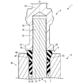
- FIG. 1 is a longitudinal sectional view of a glow plug 1.
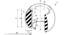
- FIG. FIG. 3 is an enlarged cross-sectional view of the rear end side of the glow plug 1. It is a figure which shows the contact member 7 before assembling
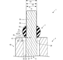
- FIG. 3 is an enlarged cross-sectional view of the rear end side of the glow plug 1 in the process of assembling the contact member 7 to the glow plug 1.
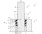
- FIG. 3 is an enlarged cross-sectional view of the rear end side of the glow plug 1 in the process of assembling the contact member 7 to the glow plug 1. It is a figure which shows the contact member 107 before assembling
- FIG. 1 the whole structure of the glow plug 1 as an example is demonstrated.
- the drawings to be referred to are used for explaining the technical features that can be adopted by the present invention, and the structure of the glow plugs described is not intended to be limited only to them, but merely illustrative examples. is there.
- the axis of the metal shell 4 is defined as the axis O, and the axis O is used as a reference for explaining the positional relationship, orientation, and direction of each component constituting the glow plug 1 assembled to the metal shell 4. To do.
- the side where the ceramic heater 2 is disposed (the lower side in FIG. 1) is the tip side of the glow plug 1.
- the axis O corresponds to the “first axis” of the present invention.
- An axis P to be described later refers to the axis of the contact member 7 in a state before being assembled to the glow plug 1, and the process of assembling and after the assembling will be described with reference to the axis O.
- the axis P corresponds to the “second axis” of the present invention.
- a glow plug 1 shown in FIG. 1 is attached to a combustion chamber (not shown) of a direct injection type diesel engine, for example, and is used as a heat source for assisting ignition at engine start.
- the glow plug 1 includes a metal shell 4, a holding member 8, a ceramic heater 2, a center shaft 3, a connection terminal 5, an insulating member 6, a contact member 7, and a connection ring 85.
- the ceramic heater 2 has a round bar shape, and has a base 21 made of an insulating ceramic whose tip 22 is hemispherically curved.
- a heating element 24 having a substantially U-shaped cross section made of conductive ceramic is embedded in the base 21.
- the heating element 24 includes a heating resistor 27 and lead portions 28 and 29.
- the heating resistor 27 is disposed at the tip portion 22 of the ceramic heater 2, and both ends are folded back in a substantially U shape in accordance with the curved surface of the tip portion 22.
- the lead portions 28 and 29 are connected to both ends of the heating resistor 27 and extend substantially parallel to each other toward the rear end portion 23 of the ceramic heater 2.
- the cross-sectional area of the heat generating resistor 27 is formed to be smaller than the cross-sectional area of the lead portions 28 and 29, and heat is generated mainly in the heat generating resistor 27 when energized.
- electrode extraction portions 25 and 26 protrude in the radial direction from the lead portions 28 and 29, respectively.
- the electrode extraction portions 25 and 26 are exposed on the outer peripheral surface of the ceramic heater 2 at positions shifted from each other in the axis O direction.
- the holding member 8 is made of a cylindrical metal member extending in the direction of the axis O, and holds the body portion of the ceramic heater 2 in the radial direction in its own cylindrical hole 84.
- the front end portion 22 and the rear end portion 23 of the ceramic heater 2 are respectively exposed from both ends of the holding member 8.
- a thick collar portion 82 is formed on the rear end side of the body portion 81 of the holding member 8. At the rear end of the collar portion 82, a stepped metal fitting portion 83 that engages with a tip portion 41 of the metal shell 4 described later is formed.
- the electrode extraction portion 25 formed on the tip side is in contact with the inner peripheral surface of the cylindrical hole 84 of the holding member 8, and the electrode extraction portion 25 and the holding member 8 are in contact with each other. Electrically connected.
- a metallic cylindrical connection ring 85 is press-fitted into the rear end portion 23 of the ceramic heater 2 exposed to the rear end side from the metal fitting engaging portion 83 of the holding member 8.
- the electrode extraction part 26 of the ceramic heater 2 is in contact with the inner peripheral surface of the connection ring 85, and the electrode extraction part 26 and the connection ring 85 are electrically connected.
- the electrode extraction portion 25 is electrically connected to the metal shell 4 by joining a distal end portion 41 of the metal shell 4 to be described later to a metal fitting engaging portion 83 of the holding member 8.
- the connection ring 85 connected to the electrode extraction portion 26 is disposed in the metal shell 4, but the ceramic heater 2 and the metal shell 4 are positioned by the holding member 8, and the connection ring 85 and the metal shell 4 are directly connected. Is maintained in an insulated state.
- the metal shell 4 is a long and thin cylindrical metal member having a shaft hole 43 penetrating in the direction of the axis O.
- the front end portion 41 of the metal shell 4 is engaged with the outer periphery of the metal fitting engaging portion 83 of the holding member 8 described above, and is electrically connected to the electrode extraction portion 25 of the ceramic heater 2 via the holding member 8.
- Laser welding is performed on the joint portion between the tip portion 41 and the metal fitting engagement portion 83, and the metal shell 4 and the holding member 8 are integrally joined.
- the middle body portion 44 between the front end portion 41 and the rear end portion 45 of the metal shell 4 is formed long in the direction of the axis O, and the glow plug 1 is attached to the engine head (not shown) of the internal combustion engine on the rear end side outer peripheral surface.
- the attachment part 42 in which the screw thread for attaching to is formed is provided.
- a tool engaging portion 46 that engages with a tool used when the glow plug 1 is mounted on the engine head is formed with a hexagonal cross section.
- a taper portion 47 is formed on the inner peripheral surface of the shaft hole 43 at the rear end portion 45 of the metal shell 4 so as to extend in a taper shape from the shaft hole 43 to the opening of the rear end 48.
- the middle shaft 3 is a rod-shaped metal member extending in the direction of the axis O, and is inserted through the shaft hole 43 of the metal shell 4.
- the middle body portion 33 between the front end portion 31 and the rear end portion 32 of the middle shaft 3 is formed to have a smaller outer diameter than the front end portion 31 and the rear end portion 32.
- a small-diameter ring engagement portion 34 is formed at the distal end portion 31 to engage with the inner periphery of the connection ring 85. As the ring engaging portion 34 engages with the connection ring 85, the ceramic heater 2 and the middle shaft 3 are integrally coupled along the axis O via the connection ring 85.
- the middle shaft 3 is electrically connected to the electrode extraction portion 26 of the ceramic heater 2 via the connection ring 85.
- the middle shaft 3 and the metal shell 4 are directly maintained in an insulated state by the shaft hole 43.
- the rear end portion 32 of the middle shaft 3 includes a connection end portion 36 that protrudes from the rear end 48 of the metal shell 4, and a connection base portion that connects between the connection end portion 36 and the middle body portion 33. 37.
- the connecting end portion 36 is formed with a locking portion 39 having a knurled surface treatment on the outer peripheral surface.
- the outer diameter of the connection end portion 36 including the locking portion 39 is smaller than the outer diameter of the connection base portion 37.
- a shoulder 38 that connects the connection end 36 and the connection base 37 in a tapered shape is formed between the connection end 36 and the connection base 37.
- the contact member 7 and the insulating member 6 are disposed at the rear end portion 32 of the middle shaft 3. Although the contact member 7 will be described later, the contact member 7 is disposed between the inner peripheral surface of the shaft hole 43 of the metal shell 4 and the connection base portion 37 of the middle shaft 3, and holds the middle shaft 3 in the shaft hole 43. While suppressing the deflection of the middle shaft 3, the airtightness of the shaft hole 43 is maintained.
- the insulating member 6 is a cylindrical body formed of a member having heat resistance and insulating properties, such as nylon (registered trademark), for example, in order to prevent a short circuit due to contact between the metal shell 4 and the center shaft 3 and the connection terminal 5 (described later). It is.
- the insulating member 6 is inserted through the rear end portion 32 of the middle shaft 3 and is positioned by contacting the tapered portion 63 provided on the outer periphery of the tapered portion 47 of the metal shell 4 with the taper portion 47 of the metal shell 4. Maintain insulation.
- connection terminal 5 is disposed in contact with the rear end 65.
- the connection terminal 5 and the metal shell 4 are maintained in an insulated state.
- connection terminal 5 is fixed to the connection end 36 of the central shaft 3.
- the connection terminal 5 has a cap-shaped body portion 52 that covers the connection end portion 36, and a pin-shaped protrusion 53 projects from the body portion 52 to the rear end side.
- a flange portion 51 is provided that protrudes in the radial direction over the entire circumference.
- connection terminal 5 is pressed inward from the outer periphery of the trunk portion 52 in a state where the connection terminal 5 is pressed toward the tip end in the axis O direction, and the inner peripheral surface of the trunk portion 52 is firmly attached to the locking portion 39 of the connection end portion 36. It is locked to. Since the locking portion 39 has a knurled shape, the fixing force of the body 52 to be pressed by crimping to the locking portion 39 is increased, and the connection terminal 5 and the central shaft 3 are fixed integrally, and both Electrically connected.
- the glow plug 1 When the glow plug 1 is attached to the engine head (not shown), a plug cap (not shown) is fitted to the protrusion 53 of the connection terminal 5.
- the heating element 24 (see FIG. 1) of the ceramic heater 2 is connected to one end side of the heating resistor 27 grounded to the engine via the holding member 8 and the metal shell 4, and to the plug cap via the connection terminal 5 and the middle shaft 3. When it is energized between the other end side connected, it generates heat.
- the contact member 7 is a member disposed between the inner peripheral surface of the shaft hole 43 of the metal shell 4 and the connection base portion 37 of the middle shaft 3, and holds the middle shaft 3 in the shaft hole 43. While suppressing the deflection of the middle shaft 3, the airtightness of the shaft hole 43 is maintained.
- the contact member 7 is formed in a cylindrical shape using a material having heat resistance, insulation and elasticity, for example, fluorine rubber, acrylic rubber, silicon rubber or the like.
- the hardness of the contact member 7 is preferably 60 to 80 in Knoop hardness.
- the abutting member 7 has a cylindrical shape having a cylindrical hole 76 extending in the extending direction of its own axis P (hereinafter also referred to as “axis P direction”), and is in a state before being assembled to the glow plug 1.
- the cross-sectional shape is substantially D-shaped. More specifically, when the cylindrical contact member 7 is cut (divided) into two pieces along a plane including the axis P of the contact member 7, each piece has a cross section at two locations. In the present embodiment, attention is paid to one of the two cross sections 75 formed in the fragment, and when the outline 70 of the cross section 75 is viewed, the outline 70 has the following form.
- the contour line 70 includes three contour portions, ie, a second contour portion 71, a first contour portion 72, and a third contour portion 73, as contour portions partially constituting the contour line 70 (line segments constituting the contour line).
- the second contour portion 71 is a contour portion extending linearly along the axis P.
- the first contour portion 72 is a contour portion that extends along the axis P, but extends in a curved shape that swells outward in the radial direction orthogonal to the axis P.
- the third contour portion 73 is a contour portion that connects the second contour portion 71 and the first contour portion 72 at the end on the same side in the direction of the axis P, and has a curved shape that bulges outward in the cross section 75. Make. Moreover, the connection point of the 1st outline part 72 and the 3rd outline part 73 is made into the both ends of the up-and-down (front-rear) of the contact member 7 in the axis line P direction.
- the first contour portion 72 is disposed on the outer side in the radial direction than the second contour portion 71, and the length in the axis P direction is longer than that of the second contour portion 71. Therefore, the third contour portion 73 extends radially outward from the end portion of the second contour portion 71 and is connected to the end portion of the first contour portion 72. Further, the contour line 70 forms a mirror image with reference to the center position in the direction of the axis P (indicated by a two-dot chain line AA in FIG. 3). That is, the contact member 7 has a symmetrical shape in the axis P direction.
- the abutting member 7 having such a cross-sectional shape provides the following rules for the shapes of the second contour portion 71 and the first contour portion 72.
- the first contour portion 72 is a curved contour portion that swells outward in the radial direction of the axis P, and the curvature radius of the first contour portion 72 is R1.
- the second contour portion 71 is a contour portion extending linearly. However, if the second contour portion 71 is a curved contour portion having a radius of curvature R2, the second contour portion 71 is a curve with R2 being infinite. It can also be regarded as a contoured portion.
- the relationship between the curvature radius R2 of the second contour portion 71 and the curvature radius R1 of the first contour portion 72 is defined to satisfy R1 ⁇ R2.
- the first contour portion 72 that bulges outward in the radial direction has a larger bulge in the radial direction than the second contour portion 71 that swells linearly (expands radially inward according to the above assumption).
- the cross-sectional shape of the contact member 7 it is defined that the length L1 along the extending direction of the axis P is longer than the length L2 along the orthogonal direction (that is, the radial direction) (that is, satisfying L1> L2). ing.
- Such an abutting member 7 can be manufactured without requiring any particular change other than the method of manufacturing an ordinary O-ring and the shape of its mold.
- compression molding for manufacturing a contact member 7 by compressing a mold having a shape corresponding to the outer shape of the contact member 7 from the upper and lower sides of the sheet made of fluororubber as a material.
- the present invention is not limited thereto, and it is possible to use injection molding in which a material such as fluororubber is injected and molded into a split mold having a cavity whose internal shape is the shape of the contact member 7 described above. .
- cutting out by cutting an annular member (ring) made of a material such as fluororubber.
- the glow plug 1 having such a structure is roughly assembled as follows.
- An element molded body that is the original form of the heating element 24 of the ceramic heater 2 is formed by injection molding using conductive ceramic powder, a binder, or the like as a raw material.
- a base compact that is the original form of the base 21 of the ceramic heater 2 is formed as a two-part compact by die press molding using insulating ceramic powder as a raw material. In a state where the element molded body is held between the base molded body, it is pressed and compressed.
- the ceramic heater 2 having a rod shape and a hemispherical tip is formed by polishing the outer peripheral surface through a baking process such as a binder removal process and a hot press.
- the manufacturing method of the ceramic heater 2 can be changed as appropriate.
- a method for producing a base molded body one molded body is previously molded and placed in a mold, an element molded body is placed thereon, further filled with an insulating ceramic powder, and press-compressed. Can be applied.
- the ceramic heater 2 is press-fitted into a connection ring 85 formed of a steel material such as stainless steel in a pipe shape, and the connection ring 85 and the electrode extraction portion 26 are electrically connected.
- the ceramic heater 2 is press-fitted into the holding member 8 formed in a predetermined shape, and the holding member 8 and the electrode extraction portion 25 are electrically connected.
- the central shaft 3 is formed by subjecting a rod-shaped member made of an iron-based material (for example, Fe—Cr—Mo steel) cut to a certain size to plastic processing, cutting, or the like. In a state where the ring engaging portion 34 of the middle shaft 3 is engaged with the connection ring 85 fitted to the ceramic heater 2, the matching portion is laser-welded so that the middle shaft 3 and the ceramic heater 2 are joined together.
- a cylindrical metal shell 4 is formed from an iron-based material such as S45C, and a thread is rolled on the mounting portion 42. Further, a taper portion 47 is formed on the inner peripheral surface of the shaft hole 43 at the rear end portion 45 of the metallic shell 4 by cutting or the like so as to extend from the shaft hole 43 to the opening of the rear end 48.
- the central shaft 3 integrated with the ceramic heater 2 and the like is inserted into the shaft hole 43 of the metal shell 4.
- the joining portion of the metal shell 4 and the holding member 8 is laser welded, and both are joined together.
- the contact member 7 is fitted to the rear end portion 32 of the middle shaft 3 protruding from the rear end 48 of the metal shell 4.
- the contact member 7 since the contact member 7 has a symmetrical shape (enantiomer) in the direction of the axis P, the orientation in the direction of the axis P when the contact member 7 is fitted to the rear end portion 32 of the middle shaft 3. Is not questioned.
- the inner diameter C ⁇ b> 1 of the cylindrical hole 76 of the contact member 7 is formed larger than the outer diameter C ⁇ b> 2 of the connection end portion 36 of the middle shaft 3.
- the tip position B1 (shoulder portion 38) of the shoulder portion 38 of the middle shaft 3 is more than the tip position B2 of the taper portion 47 of the metal shell 4 (corresponding to the start position of the taper portion 47 in the shaft hole 43).
- the connection base 37 corresponds to the boundary). Therefore, after the connection end portion 36 is inserted, the contact member 7 reaches the shoulder portion 38 of the middle shaft 3 before contacting the tapered portion 47 of the metal shell 4.
- the inner diameter C1 of the cylindrical hole 76 of the contact member 7 is formed to be smaller than the outer diameter C3 of the connection base portion 37 of the middle shaft 3. Therefore, the abutting member 7 that has reached the shoulder portion 38 is further pushed toward the distal end side in the direction of the axis O, so that the cylindrical hole 76 is pushed and expanded along the taper of the shoulder portion 38.
- the third contour portion 73 (see FIG. 3) in the cross section 75 of the contact member 7 is pressed against the tapered shoulder portion 38. Since the third contour portion 73 has a curved shape that swells outward in the cross section 75, the inner diameter of the contact member 7 can be smoothly spread along the taper of the shoulder portion 38.
- the first contour portion 72 has a curved shape with a curvature radius R ⁇ b> 1 that swells outward in the radial direction of the contact member 7. Therefore, the deformation in which the radial thickness of the abutting member 7 is compressed is smoother than that of the second contour portion 71 having a linear shape (the curvature radius R2 is infinite in the case of a curved shape). Can be done.
- the abutting member 7 is in a state where the inner diameter is first widened by the shoulder portion 38 of the middle shaft 3 and the inner peripheral surface of the cylindrical hole 76 is in contact with the outer peripheral surface of the connection base portion 37.
- the contact member 7 Since the outer diameter is narrowed by the taper portion 47 of the metal shell 4 in the state as it is (that is, in a state where there is no large gap between the center shaft 3), the contact member 7 is caught inwardly. It does not occur and no circumferential twist or wrinkle occurs.
- the pressing of the contact member 7 between the inner peripheral surface of the shaft hole 43 and the connection base 37 may be performed using a jig, or may be performed by the insulating member 6 as shown in FIG. Good.
- the second contour portion 71 of the contact member 7 is linear along the axis P of the contact member 7. Therefore, when the contact member 7 is pushed in along the axis O and mainly in the direction along its own axis P, the second contour portion 71 supports the entire contact member and suppresses bending and entanglement. Can function as. For this reason, in the 2nd outline part 71, it is suppressed that the contact member 7 bends and wrinkles.
- the contact member 7 when the contact member 7 is disposed between the inner peripheral surface of the shaft hole 43 and the connection base portion 37, the contact member 7 is guided to the center of the shaft hole 43 by the tapered portion 47 of the metal shell 4. The For this reason, for example, even when an axis deviation occurs between the axis O of the metal shell 4 and the axis of the middle shaft 3, the middle shaft 3 is guided to the center of the shaft hole 43 via the contact member 7. An axial deviation from the third axis can be corrected.
- the contact member 7 since the contact member 7 has the first contour portion 72 having a radius of curvature R1 and bulging outward in the radial direction in its cross section, it can be elastically deformed smoothly. Furthermore, by having the linear second contour portion 71, the second contour portion 71 is reliably disposed between the inner peripheral surface of the shaft hole 43 and the connection base portion 37 without causing bending or wrinkling. Further, the radial thickness of the contact member 7 in which the outline 70 of the cross section before assembly is D-shaped is compressed and deformed so as to be flattened along the axis P. Therefore, deformation is performed such that the thickest portion (near the center in the direction of the axis P) moves to the thin side (both ends in the direction of the axis P).
- the contact member 7 does not produce a deformed portion having a high internal stress locally, and is unlikely to break even when the glow plug 1 receives vibration or the like from the outside.
- the assembled contact member 7 does not maintain the shape of the mirror image body in the direction of the axis P, and by such deformation, the contact member 7 reliably adheres to both the inner peripheral surface of the shaft hole 43 and the connection base portion 37. Therefore, sufficient resistance can be obtained for both the outer peripheral surface of the connection base 37 and the inner peripheral surface of the inner peripheral surface of the shaft hole 43. For this reason, the abutting member 7 can reliably hold the middle shaft 3 in the shaft hole 43, and can suppress the deflection of the middle shaft 3 when the glow plug 1 receives vibration or the like from the outside.
- the contact member 7 is provided at two points in the radial direction between the outer peripheral surface of the connection base portion 37 of the middle shaft 3 that surrounds the circumference of the axis O and the inner peripheral surface of the shaft hole 43 of the metal shell 4. And a contact surface between the connection base 37 and the inner peripheral surface of the shaft hole 43.
- the positional displacement of the contact member 7 may occur due to vibration associated with the use of the glow plug 1.
- the contact member 7 having a contact surface between the connection base portion 37 and the inner peripheral surface of the shaft hole 43 at two points in the radial direction can maintain the size of the contact surface only by shifting the contact position between them. Can do.
- the contact member 7 can maintain the state contact
- the contact member 7 satisfies L1> L2
- L1> L2 when the contact member 7 is disposed between the inner peripheral surface of the shaft hole 43 and the middle shaft 3, the inner periphery of the shaft hole 43 in the direction along the axis O.
- the length interposed between the surface and the middle shaft 3 can be secured longer. For this reason, the middle shaft 3 can be more reliably held in the shaft hole 43, and the shake of the middle shaft 3 when external vibration is applied to the middle shaft 3 can be more reliably suppressed.
- the insulating member 6 When the contact member 7 is disposed between the inner peripheral surface of the shaft hole 43 and the connection base portion 37, the insulating member 6 is fitted to the rear end portion 32 of the middle shaft 3 as shown in FIG. 2.
- the taper portion 63 of the insulating member 6 is in contact with the taper portion 47 of the metal shell 4 and is positioned, and is fitted to the rear end portion 32 of the middle shaft 3.
- the body portion 52 of the connection terminal 5 is crimped, and the connection terminal 5 is fixed to the connection end portion 36 of the center shaft 3 to complete the glow plug 1.
- the contact member 7 has a shape in which both upper and lower (front and rear) ends thereof are connection points between the first contour portion 72 and the third contour portion 73.
- the ratio of the third contour portion 73 to the contour line 70 may be further increased so that the upper and lower end portions in the direction of the axis P constitute the third contour portion.
- the contour portion 170 of the cross section 175 in the contour portion 170 of the cross section 175, there is no third contour portion, and the second contour portion 171 and the first contour portion 172 are directly connected. It may have a D-shape.
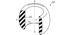
- the contour portion 270 of the cross section 275 does not form a mirror body with respect to the center position in the axis P direction, that is, has an asymmetric shape in the axis P direction. May be.
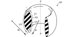
- the second contour portion 371 may have a curved shape with a radius of curvature R2 that swells inward in the radial direction.
- the relationship between the radius of curvature R1 of the first contour portion 372 bulging outward in the radial direction and the radius of curvature R2 of the second contour portion 371 may satisfy R1 ⁇ R2, as in the present embodiment.
- the first contour portion 372 having a larger bulge than the second contour portion 371 is elastically deformed smoothly.
- the second contour portion 371 having a smaller bulge than the first contour portion 372 and closer to a linear shape can function as a core that supports the entire contact member and suppresses bending and entanglement.
- the contact members 107, 207, and 307 shown in FIGS. 6, 7, and 8 are the same as the contact member 7 of the present embodiment shown in FIG. That is, in the cross section, the length L1 in the extending direction of the axis P is longer than the length L2 in the orthogonal direction (radial direction), that is, a flat shape (L1> L2) short in the radial direction. More preferably, the configuration is such that the radial length L2 in the cross section is not more than half the length P1 in the axis P direction (L1 / 2 ⁇ L2). However, depending on the selection of materials and the configuration of details, this relationship (half of the length in the direction of the axis P> diameter in the radial direction (L1 / 2 ⁇ L2)) may deviate in a range satisfying L1> L2.
- the glow plug 1 includes the ceramic heater 2, but the glow plug 1 is not limited thereto, and a sheathed heater in which a coiled heating resistor and a control resistor are arranged in a metal sheath tube whose tip is closed in a hemispherical shape. You may prepare. Moreover, the glow plug of the form which does not have the holding member 8 but hold
- a hook-shaped or protruding stopper that may cause a slight step may be provided on the distal end side of the connection base portion 37 of the middle shaft 3. In this way, even if the contact member 7 is displaced due to vibration or the like, for example, it is possible to prevent the contact member 7 from being moved to the middle barrel portion 33 side by the stopper. Further, the contact member 7 may be disposed in a non-contact state with the insulating member 6 between the inner peripheral surface of the shaft hole 43 and the connection base portion 37.
- the contact member 7 of the present embodiment is premised on securing the airtightness of the shaft hole 43, and it is preferable to hold the middle shaft 3 and suppress the deflection of the middle shaft 3 in the radial direction. Therefore, when the contact member 7 is configured to continuously adhere to each of the inner peripheral surface of the shaft hole 43 and the outer peripheral surface of the central shaft 3 while making a round in the circumferential direction of the axis O, the vibration-proof property and the air-tightness. Can be ensured.
- the tip 31 corresponds to “one end” and the connection end 36 corresponds to “other end”.
- the connection base 37 corresponds to a “rear end body”.
Landscapes
- Engineering & Computer Science (AREA)
- Chemical & Material Sciences (AREA)
- Combustion & Propulsion (AREA)
- Mechanical Engineering (AREA)
- General Engineering & Computer Science (AREA)
- Resistance Heating (AREA)
Abstract
Description
Claims (5)
- 通電によって発熱する発熱抵抗体を自身の先端部に有するヒータと、
自身の軸線である第1軸線に沿って延びる軸孔を有する筒状に形成され、自身の先端部において前記ヒータを直接または間接的に保持する主体金具と、
棒状に形成され、前記主体金具の前記軸孔に当該軸孔の内周面に対し間隙をおいて配置されると共に、自身の一端部が前記ヒータの後端部に接続され、自身の他端部が前記主体金具の後端から突出される中軸と、
環状に形成され、前記軸孔の後端部において前記軸孔に挿入されて、前記軸孔の内周面と前記中軸とのそれぞれに当接した状態に配置される絶縁性の弾性部材からなる当接部材と、
を備えるグロープラグであって、
グロープラグに組み付ける前の前記当接部材を、前記当接部材の軸線である第2軸線を含む平面にて切断した場合に、2つの断面のうちの一方の断面の輪郭線をみたときに、前記当接部材は、前記輪郭線を部分的に構成する輪郭部として、
前記第2軸線に沿いつつも径方向外向きに膨らむ曲率半径R1の曲線状に延びる第一輪郭部と、
前記第2軸線に沿いつつも、曲率半径R2がR1<R2を満たして径方向内向きに膨らむ曲線状または直線状に延びる第二輪郭部と、
を有することを特徴とするグロープラグ。 - 前記当接部材は、前記一方の断面において、前記第2軸線の延伸方向に沿う長さが前記第2軸線の直交方向に沿う長さよりも長いことを特徴とする請求項1に記載のグロープラグ。
- 前記中軸は、
前記主体金具の前記第1軸線の延伸方向において前記軸孔の内周面の前記後端部と向き合う位置に配置される部位であり、前記他端部よりも前記径方向に大きく形成される後端側胴部と、
前記後端側胴部と前記他端部とをテーパ状に結ぶ肩部と、
をさらに備え、
前記主体金具は、前記軸孔の前記後端部において、前記肩部の先端側の端部よりも先端側から、前記第1軸線の延伸方向の後端側へ向けてテーパ状に広がるテーパ部をさらに備え、
前記当接部材は、前記第二輪郭部が前記中軸と当接し、前記第一輪郭部が前記テーパ部よりも先端側で前記軸孔の内周面と当接して配置されていることを特徴とする請求項1または2に記載のグロープラグ。 - 前記当接部材の前記輪郭線をみたときに、前記当接部材は、前記輪郭部を部分的に構成する輪郭部として、一端が前記第二輪郭部に接続し、前記一端から他端にかけて前記第2軸線に沿いつつも前記径方向外向きに延び、前記他端が前記第一輪郭部に接続し、前記第一輪郭部との接続点が前記第2軸線の延伸方向における前記当接部材の端部をなす第三輪郭部をさらに備えることを特徴とする請求項3に記載のグロープラグ。
- 前記輪郭線は、前記第2軸線の延伸方向における中央の位置を基準に鏡像体をなすことを特徴とする請求項4に記載のグロープラグ。
Priority Applications (4)
| Application Number | Priority Date | Filing Date | Title |
|---|---|---|---|
| KR1020137020826A KR101638670B1 (ko) | 2011-01-25 | 2012-01-16 | 글로 플러그 |
| US13/991,369 US20130248508A1 (en) | 2011-01-25 | 2012-01-16 | Glow plug |
| JP2012515276A JP5806211B2 (ja) | 2011-01-25 | 2012-01-16 | グロープラグ |
| EP12739873.3A EP2669578B1 (en) | 2011-01-25 | 2012-01-16 | Glow plug |
Applications Claiming Priority (2)
| Application Number | Priority Date | Filing Date | Title |
|---|---|---|---|
| JP2011013388 | 2011-01-25 | ||
| JP2011-013388 | 2011-01-25 |
Publications (1)
| Publication Number | Publication Date |
|---|---|
| WO2012102109A1 true WO2012102109A1 (ja) | 2012-08-02 |
Family
ID=46580681
Family Applications (1)
| Application Number | Title | Priority Date | Filing Date |
|---|---|---|---|
| PCT/JP2012/050708 Ceased WO2012102109A1 (ja) | 2011-01-25 | 2012-01-16 | グロープラグ |
Country Status (5)
| Country | Link |
|---|---|
| US (1) | US20130248508A1 (ja) |
| EP (1) | EP2669578B1 (ja) |
| JP (1) | JP5806211B2 (ja) |
| KR (1) | KR101638670B1 (ja) |
| WO (1) | WO2012102109A1 (ja) |
Families Citing this family (3)
| Publication number | Priority date | Publication date | Assignee | Title |
|---|---|---|---|---|
| US9574774B2 (en) * | 2014-03-27 | 2017-02-21 | Kyocera Corporation | Heater and ignition apparatus equipped with the heater |
| US10253982B2 (en) * | 2014-12-22 | 2019-04-09 | Ngk Spark Plug Co., Ltd. | Glow plug with pressure sensor |
| DE102016114929B4 (de) * | 2016-08-11 | 2018-05-09 | Borgwarner Ludwigsburg Gmbh | Druckmessglühkerze |
Citations (3)
| Publication number | Priority date | Publication date | Assignee | Title |
|---|---|---|---|---|
| JPH0484863U (ja) * | 1990-11-29 | 1992-07-23 | ||
| JP2006112478A (ja) * | 2004-10-13 | 2006-04-27 | Nok Corp | 往復動用密封リング |
| JP2007292444A (ja) | 2006-03-30 | 2007-11-08 | Ngk Spark Plug Co Ltd | グロープラグ |
Family Cites Families (6)
| Publication number | Priority date | Publication date | Assignee | Title |
|---|---|---|---|---|
| EP0989370A3 (en) * | 1998-09-25 | 2005-04-20 | Delphi Technologies, Inc. | Glow sensor-metal tip |
| DE10012266A1 (de) * | 2000-03-14 | 2001-09-20 | Bosch Gmbh Robert | Glühstiftkerze für eine Brennkraftmaschine |
| JP2002013736A (ja) * | 2000-06-27 | 2002-01-18 | Denso Corp | グロープラグ |
| US7329836B2 (en) * | 2006-03-30 | 2008-02-12 | Ngk Spark Plug Co., Ltd. | Glow plug with O-ring seal |
| JP4897467B2 (ja) * | 2006-12-19 | 2012-03-14 | 日本特殊陶業株式会社 | グロープラグおよびその製造方法 |
| JP5964547B2 (ja) * | 2011-01-25 | 2016-08-03 | 日本特殊陶業株式会社 | グロープラグおよびその製造方法 |
-
2012
- 2012-01-16 JP JP2012515276A patent/JP5806211B2/ja active Active
- 2012-01-16 US US13/991,369 patent/US20130248508A1/en not_active Abandoned
- 2012-01-16 EP EP12739873.3A patent/EP2669578B1/en active Active
- 2012-01-16 KR KR1020137020826A patent/KR101638670B1/ko not_active Expired - Fee Related
- 2012-01-16 WO PCT/JP2012/050708 patent/WO2012102109A1/ja not_active Ceased
Patent Citations (3)
| Publication number | Priority date | Publication date | Assignee | Title |
|---|---|---|---|---|
| JPH0484863U (ja) * | 1990-11-29 | 1992-07-23 | ||
| JP2006112478A (ja) * | 2004-10-13 | 2006-04-27 | Nok Corp | 往復動用密封リング |
| JP2007292444A (ja) | 2006-03-30 | 2007-11-08 | Ngk Spark Plug Co Ltd | グロープラグ |
Also Published As
| Publication number | Publication date |
|---|---|
| KR101638670B1 (ko) | 2016-07-11 |
| EP2669578A1 (en) | 2013-12-04 |
| EP2669578A4 (en) | 2018-01-03 |
| JP5806211B2 (ja) | 2015-11-10 |
| JPWO2012102109A1 (ja) | 2014-06-30 |
| EP2669578B1 (en) | 2019-08-14 |
| KR20140037817A (ko) | 2014-03-27 |
| US20130248508A1 (en) | 2013-09-26 |
Similar Documents
| Publication | Publication Date | Title |
|---|---|---|
| JP4960118B2 (ja) | グロープラグ | |
| US7692118B2 (en) | Glow plug and method for manufacturing the same | |
| KR101558651B1 (ko) | 글로 플러그 및 그 제조방법 | |
| JP4870640B2 (ja) | グロープラグおよびその製造方法 | |
| JP5806211B2 (ja) | グロープラグ | |
| JP5964547B2 (ja) | グロープラグおよびその製造方法 | |
| JP4623645B2 (ja) | グロープラグ | |
| JP4865375B2 (ja) | グロープラグ | |
| JP5351236B2 (ja) | グロープラグ | |
| JP5740002B2 (ja) | グロープラグ | |
| JP5960494B2 (ja) | グロープラグ | |
| JP2007032877A (ja) | グロープラグおよびその製造方法 | |
| JP4890901B2 (ja) | グロープラグおよびその製造方法 | |
| JP4478626B2 (ja) | グロープラグおよびその製造方法 | |
| JP5639227B2 (ja) | グロープラグ | |
| JP4295164B2 (ja) | グロープラグ | |
| JP6203561B2 (ja) | ヒータユニットおよびそれを備えたグロープラグ |
Legal Events
| Date | Code | Title | Description |
|---|---|---|---|
| WWE | Wipo information: entry into national phase |
Ref document number: 2012515276 Country of ref document: JP |
|
| 121 | Ep: the epo has been informed by wipo that ep was designated in this application |
Ref document number: 12739873 Country of ref document: EP Kind code of ref document: A1 |
|
| WWE | Wipo information: entry into national phase |
Ref document number: 13991369 Country of ref document: US |
|
| NENP | Non-entry into the national phase |
Ref country code: DE |
|
| ENP | Entry into the national phase |
Ref document number: 20137020826 Country of ref document: KR Kind code of ref document: A |
|
| WWE | Wipo information: entry into national phase |
Ref document number: 2012739873 Country of ref document: EP |