WO2012102253A1 - 燃料電池発電システム及び燃料電池発電システムの制御方法 - Google Patents
燃料電池発電システム及び燃料電池発電システムの制御方法 Download PDFInfo
- Publication number
- WO2012102253A1 WO2012102253A1 PCT/JP2012/051400 JP2012051400W WO2012102253A1 WO 2012102253 A1 WO2012102253 A1 WO 2012102253A1 JP 2012051400 W JP2012051400 W JP 2012051400W WO 2012102253 A1 WO2012102253 A1 WO 2012102253A1
- Authority
- WO
- WIPO (PCT)
- Prior art keywords
- fuel cell
- temperature
- oxidizing gas
- fuel
- power generation
- Prior art date
- Legal status (The legal status is an assumption and is not a legal conclusion. Google has not performed a legal analysis and makes no representation as to the accuracy of the status listed.)
- Ceased
Links
Images




Classifications
-
- H—ELECTRICITY
- H01—ELECTRIC ELEMENTS
- H01M—PROCESSES OR MEANS, e.g. BATTERIES, FOR THE DIRECT CONVERSION OF CHEMICAL ENERGY INTO ELECTRICAL ENERGY
- H01M8/00—Fuel cells; Manufacture thereof
- H01M8/04—Auxiliary arrangements, e.g. for control of pressure or for circulation of fluids
- H01M8/04007—Auxiliary arrangements, e.g. for control of pressure or for circulation of fluids related to heat exchange
-
- H—ELECTRICITY
- H01—ELECTRIC ELEMENTS
- H01M—PROCESSES OR MEANS, e.g. BATTERIES, FOR THE DIRECT CONVERSION OF CHEMICAL ENERGY INTO ELECTRICAL ENERGY
- H01M8/00—Fuel cells; Manufacture thereof
- H01M8/04—Auxiliary arrangements, e.g. for control of pressure or for circulation of fluids
- H01M8/04007—Auxiliary arrangements, e.g. for control of pressure or for circulation of fluids related to heat exchange
- H01M8/04067—Heat exchange or temperature measuring elements, thermal insulation, e.g. heat pipes, heat pumps, fins
-
- H—ELECTRICITY
- H01—ELECTRIC ELEMENTS
- H01M—PROCESSES OR MEANS, e.g. BATTERIES, FOR THE DIRECT CONVERSION OF CHEMICAL ENERGY INTO ELECTRICAL ENERGY
- H01M8/00—Fuel cells; Manufacture thereof
- H01M8/04—Auxiliary arrangements, e.g. for control of pressure or for circulation of fluids
- H01M8/04298—Processes for controlling fuel cells or fuel cell systems
- H01M8/04313—Processes for controlling fuel cells or fuel cell systems characterised by the detection or assessment of variables; characterised by the detection or assessment of failure or abnormal function
- H01M8/04537—Electric variables
- H01M8/04604—Power, energy, capacity or load
- H01M8/04619—Power, energy, capacity or load of fuel cell stacks
-
- H—ELECTRICITY
- H01—ELECTRIC ELEMENTS
- H01M—PROCESSES OR MEANS, e.g. BATTERIES, FOR THE DIRECT CONVERSION OF CHEMICAL ENERGY INTO ELECTRICAL ENERGY
- H01M8/00—Fuel cells; Manufacture thereof
- H01M8/04—Auxiliary arrangements, e.g. for control of pressure or for circulation of fluids
- H01M8/04298—Processes for controlling fuel cells or fuel cell systems
- H01M8/04694—Processes for controlling fuel cells or fuel cell systems characterised by variables to be controlled
- H01M8/04701—Temperature
- H01M8/04708—Temperature of fuel cell reactants
-
- H—ELECTRICITY
- H01—ELECTRIC ELEMENTS
- H01M—PROCESSES OR MEANS, e.g. BATTERIES, FOR THE DIRECT CONVERSION OF CHEMICAL ENERGY INTO ELECTRICAL ENERGY
- H01M8/00—Fuel cells; Manufacture thereof
- H01M8/04—Auxiliary arrangements, e.g. for control of pressure or for circulation of fluids
- H01M8/04298—Processes for controlling fuel cells or fuel cell systems
- H01M8/04694—Processes for controlling fuel cells or fuel cell systems characterised by variables to be controlled
- H01M8/04746—Pressure; Flow
- H01M8/04753—Pressure; Flow of fuel cell reactants
-
- H—ELECTRICITY
- H01—ELECTRIC ELEMENTS
- H01M—PROCESSES OR MEANS, e.g. BATTERIES, FOR THE DIRECT CONVERSION OF CHEMICAL ENERGY INTO ELECTRICAL ENERGY
- H01M8/00—Fuel cells; Manufacture thereof
- H01M8/04—Auxiliary arrangements, e.g. for control of pressure or for circulation of fluids
- H01M8/04298—Processes for controlling fuel cells or fuel cell systems
- H01M8/04694—Processes for controlling fuel cells or fuel cell systems characterised by variables to be controlled
- H01M8/04746—Pressure; Flow
- H01M8/04761—Pressure; Flow of fuel cell exhausts
-
- H—ELECTRICITY
- H01—ELECTRIC ELEMENTS
- H01M—PROCESSES OR MEANS, e.g. BATTERIES, FOR THE DIRECT CONVERSION OF CHEMICAL ENERGY INTO ELECTRICAL ENERGY
- H01M8/00—Fuel cells; Manufacture thereof
- H01M8/04—Auxiliary arrangements, e.g. for control of pressure or for circulation of fluids
- H01M8/04298—Processes for controlling fuel cells or fuel cell systems
- H01M8/04694—Processes for controlling fuel cells or fuel cell systems characterised by variables to be controlled
- H01M8/04746—Pressure; Flow
- H01M8/04776—Pressure; Flow at auxiliary devices, e.g. reformer, compressor, burner
-
- H—ELECTRICITY
- H01—ELECTRIC ELEMENTS
- H01M—PROCESSES OR MEANS, e.g. BATTERIES, FOR THE DIRECT CONVERSION OF CHEMICAL ENERGY INTO ELECTRICAL ENERGY
- H01M8/00—Fuel cells; Manufacture thereof
- H01M8/06—Combination of fuel cells with means for production of reactants or for treatment of residues
- H01M8/0606—Combination of fuel cells with means for production of reactants or for treatment of residues with means for production of gaseous reactants
- H01M8/0612—Combination of fuel cells with means for production of reactants or for treatment of residues with means for production of gaseous reactants from carbon-containing material
- H01M8/0618—Reforming processes, e.g. autothermal, partial oxidation or steam reforming
-
- H—ELECTRICITY
- H01—ELECTRIC ELEMENTS
- H01M—PROCESSES OR MEANS, e.g. BATTERIES, FOR THE DIRECT CONVERSION OF CHEMICAL ENERGY INTO ELECTRICAL ENERGY
- H01M8/00—Fuel cells; Manufacture thereof
- H01M8/04—Auxiliary arrangements, e.g. for control of pressure or for circulation of fluids
- H01M8/04007—Auxiliary arrangements, e.g. for control of pressure or for circulation of fluids related to heat exchange
- H01M8/04014—Heat exchange using gaseous fluids; Heat exchange by combustion of reactants
-
- H—ELECTRICITY
- H01—ELECTRIC ELEMENTS
- H01M—PROCESSES OR MEANS, e.g. BATTERIES, FOR THE DIRECT CONVERSION OF CHEMICAL ENERGY INTO ELECTRICAL ENERGY
- H01M8/00—Fuel cells; Manufacture thereof
- H01M8/04—Auxiliary arrangements, e.g. for control of pressure or for circulation of fluids
- H01M8/04007—Auxiliary arrangements, e.g. for control of pressure or for circulation of fluids related to heat exchange
- H01M8/04014—Heat exchange using gaseous fluids; Heat exchange by combustion of reactants
- H01M8/04022—Heating by combustion
-
- Y—GENERAL TAGGING OF NEW TECHNOLOGICAL DEVELOPMENTS; GENERAL TAGGING OF CROSS-SECTIONAL TECHNOLOGIES SPANNING OVER SEVERAL SECTIONS OF THE IPC; TECHNICAL SUBJECTS COVERED BY FORMER USPC CROSS-REFERENCE ART COLLECTIONS [XRACs] AND DIGESTS
- Y02—TECHNOLOGIES OR APPLICATIONS FOR MITIGATION OR ADAPTATION AGAINST CLIMATE CHANGE
- Y02E—REDUCTION OF GREENHOUSE GAS [GHG] EMISSIONS, RELATED TO ENERGY GENERATION, TRANSMISSION OR DISTRIBUTION
- Y02E60/00—Enabling technologies; Technologies with a potential or indirect contribution to GHG emissions mitigation
- Y02E60/30—Hydrogen technology
- Y02E60/50—Fuel cells
Definitions
- the present invention relates to a fuel cell power generation system that generates power by adjusting the temperature of a fuel cell according to an output request, and a control method thereof.
- Patent Document 1 Japanese Patent Application Laid-Open No. 2003-115315 (Patent Document 1) and Japanese Patent Application Laid-Open No. 2004-349214 (Patent Document 2) reduce the temperature of oxygen gas supplied to the cathode of a fuel cell when the power generation output is increased.
- Patent Document 2 Japanese Patent Application Laid-Open No. 2003-115315 (Patent Document 1) and Japanese Patent Application Laid-Open No. 2004-349214 (Patent Document 2) reduce the temperature of oxygen gas supplied to the cathode of a fuel cell when the power generation output is increased.
- a fuel cell power generation system that keeps the temperature of the fuel cell substantially constant (for example, ⁇ 10 ° C.) is disclosed.
- Patent Document 1 since the reaction temperature is limited to ⁇ 10 ° C., the output of the fuel cell is limited, and the controllable power generation output range cannot be widened. For example, consider mounting a fuel cell power generation system on a vehicle to cover the running energy of the vehicle. In this case, electric power of several KW is required during normal driving including city driving and JC08 mode, and electric power of several tens of KW or more is required during high-speed driving of 100 Km / h or higher. However, the techniques described in Patent Document 1 and Patent Document 2 cannot meet such a demand for a wide power generation output range.
- Patent Documents 1 and 2 As described above, it is difficult for the related techniques disclosed in Patent Documents 1 and 2 to cope with changes in the amount of power generation. For this reason, the inventor has recognized that development of a fuel cell power generation system that can flexibly cope with changes in the amount of power generation is desired.
- the present invention has been made to solve such technical problems, and an object of the present invention is to provide a fuel cell power generation system capable of changing the operating temperature of a fuel cell in accordance with a power output request, and The control method is provided.
- a fuel cell power generation system includes a fuel cell that generates power by being supplied with an oxidizing gas and a fuel gas, and a temperature of the oxidizing gas supplied to the oxidizing gas supply port of the fuel cell.
- a temperature adjusting unit that adjusts the temperature of the oxidizing gas supplied to the oxidizing gas supply port when the output requirement for the fuel cell is high compared to when the output requirement is low. By controlling the temperature control unit, when the output request for the fuel cell is high, the operating temperature of the fuel cell is made higher than when the output request is low.
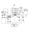
- FIG. 1 is a block diagram showing the configuration of the fuel cell power generation system according to the first embodiment of the present invention.
- FIG. 2 is a characteristic diagram showing the relationship between the power output ratio and the burner combustion heat value ratio of the fuel cell power generation system according to the embodiment of the present invention.
- FIG. 3 is a characteristic diagram showing the relationship between the power output ratio and the system efficiency of the fuel cell power generation system according to the embodiment of the present invention.
- FIG. 4 is a characteristic diagram showing the relationship between the power output ratio and the oxidizing gas excess ratio of the fuel cell power generation system according to the embodiment of the present invention.
- FIG. 5 is a flowchart showing the procedure of the output control process of the fuel cell power generation system according to the first embodiment of the present invention.
- the fuel cell 11 is, for example, a solid oxide fuel cell (SOFC), which generates electric power from the reformed fuel supplied to the anode electrode 11b and the air supplied to the cathode electrode 11a.
- SOFC solid oxide fuel cell
- the fuel cell power generation system 100 changes the operating temperature of the fuel cell 11 by driving the combustion burner 23 and supplying heated air to the fuel cell 11 to respond to the change in output power. .
- the operation temperature of the fuel cell 11 at normal time is set to 700 ° C.
- the operation temperature is changed within the range of ⁇ 50 ° C., that is, 650 ° C. to 750 ° C. with respect to this temperature.
- the fuel reformer 15 operates at a temperature of about 700 ° C.
- air is sent out from the first air blower 12 by driving the first air blower 12.
- the air sent out from the first air blower 12 passes through the low temperature side of the air heating heat exchanger 13, that is, the side that absorbs heat, and is then introduced into the oxidizing gas supply port of the cathode electrode 11a.
- high-temperature exhaust gas discharged from the reformer heating heat exchanger 16 is introduced to the high temperature side of the air heating heat exchanger 13, that is, the side from which heat is released. Therefore, the air sent from the first air blower 12 is heated to a temperature 200 ° C. to 300 ° C. lower than the temperature of the fuel cell 11 by the heat of the exhaust gas, and is introduced into the oxidizing gas supply port of the cathode electrode 11a.
- the oxidizing gas is not limited to air, and a gas containing oxygen can be used.
- the temperature of the air introduced into the oxidizing gas supply port of the cathode electrode 11a is, for example, 200 ° C. to 300 ° C. lower than the normal operating temperature of the fuel cell 11 (650 ° C. to 750 ° C.). For this reason, the air introduced into the cathode electrode 11a is heated by the thermal energy generated at the time of power generation of the fuel cell 11, reaches a temperature substantially the same as the temperature of the fuel cell 11, and is discharged from the outlet of the cathode electrode 11a. Therefore, the greater the difference between the operating temperature of the fuel cell 11 and the temperature of the introduced air, the greater the amount of heat transferred from the fuel cell 11 to the air.
- the heat radiation amount in the fuel cell 11 is increased.
- the amount of heat dissipation increases beyond the amount of heat that can be transferred to the air, the operating temperature of the fuel cell 11 rises and exceeds the normal temperature. For this reason, it is necessary to control the rotation speed of the first air blower 12 to increase the amount of air introduced into the oxidizing gas supply port. That is, by increasing the amount of air, the amount of heat that can be transferred from the fuel cell 11 to the air can be increased, and as a result, the operating temperature of the fuel cell 11 can be lowered to a normal temperature.
- the burner fuel heating value ratio increases rapidly as the power output ratio increases from “1”, and the power output When the ratio is “2.4”, the burner fuel heating value ratio reaches “1.4”.
- the burner fuel heat generation ratio is about “0.2” when the power output ratio is “2.4”. Thereafter, as the output ratio increases, the burner fuel heat generation ratio increases linearly.
- FIG. 3 shows the relationship between the system efficiency and the output power when the amount of air introduced and the amount of fuel in the combustion burner 23 are changed in response to the change in output power.
- a curve P3 shows a case where the operating temperature of the fuel cell 11 is 650 ° C.
- a curve P4 shows a case where the operating temperature of the fuel cell 11 is 750 ° C.
- the system efficiency is calculated by the following equation (1).
- the efficiency of the fuel cell 11 is high, so that a power generation range wider than that when operated at a relatively low temperature, for example, 650 ° C. is covered. can do.
- a relatively low temperature for example, 650 ° C.
- it is necessary to keep the fuel cell 11 at a high temperature it is necessary to use a lot of materials or to use expensive materials in order to maintain the durability. This leads to cost problems.
- a relatively low output (several kW) is assumed as the power required for normal driving such as driving in the city and JC08 mode.
- relatively high power (several tens of kW) is required.
- the fuel cell 11 capable of actively changing the operation temperature exhibits an effect under such use conditions. That is, when generating relatively low output power that occupies most of the operation period, the operating temperature of the fuel cell 11 is set to a low value, for example, 650 ° C., and the fuel cell is at the optimum point of high efficiency at this operating temperature. 11 is driven. Further, when generating high output power, the operating temperature of the fuel cell 11 is raised to, for example, 750 ° C.
- the fuel cell 11 that is compact in shape, can widen the range of output power, and can minimize the period of high-temperature operation that accelerates deterioration of durability performance.
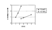
- FIG. 4 is a characteristic diagram showing changes in the oxidizing gas (air in the present embodiment) and the oxidizing gas excess rate according to the output ratio of electric power.
- the oxidizing gas excess rate is obtained by the following equation (2).
- the oxidant gas excess ratio is a ratio of the oxidant gas excess ratio under each condition when the power output ratio is “1” and the oxidant gas excess ratio when the operating temperature of the fuel cell 11 is 650 ° C. is “1”. It is.
- the air also serves as a refrigerant for adjusting the temperature of the fuel cell. Therefore, the actual supply amount with respect to the required amount of oxidant gas (air amount) varies greatly with changes in the operating state of the fuel cell.
- the pressure in the flow path increases.
- an increase in the pressure of each flow path is prevented by adjusting the opening degree of the fuel flow path pressure adjustment valve 18 and the exhaust flow path pressure adjustment valve 19.
- the pressure difference between the cathode electrode 11a and the anode electrode 11b of the fuel cell 11 can be reduced, and the pressure of the fuel gas supplied to the fuel reformer 15 can be set to a desired pressure.
- step S11 when the power generation output command is output from the host system, the control unit 31 receives the power generation output command.
- step S13 the control unit 31 determines the fuel flow path pressure adjustment valve 18 and the exhaust flow path according to the flow rates of the air blowers 12 and 21 and the flow rates of the fuel pumps 14 and 22 set in the process of step S12.
- the opening degree of the pressure regulating valve 19 is determined.
- step S17 the control unit 31 transmits a rotation speed adjustment signal to the first air blower 12 and the first fuel pump 14 so that the flow rate determined in the process of step S12 is obtained.
- the first air blower 12 and the first fuel pump 14 are adjusted to have the determined flow rates.
- the temperature of the fuel cell 11 can be set to a temperature suitable for the power consumption of the external load, and the pressure of the exhaust gas can be controlled to a suitable pressure.
- the air sent from the first air blower 12 is supplied to the oxidizing gas supply port of the cathode 11a of the fuel cell 11 and the oxidizing gas is supplied. Heated air sent from the combustion burner 23 is introduced into the supply port. Therefore, when high output power is required, the operating temperature of the fuel cell 11 is increased by increasing the heat value of the combustion burner 23 and increasing the temperature of the air introduced into the oxidizing gas supply port of the cathode electrode 11a. Therefore, it is possible to greatly improve the operable output. For example, as shown in the characteristic diagram of FIG.
- the power output ratio when the operating temperature of the fuel cell 11 is only 650 ° C., the power output ratio is in the range of 1 to 2.4, but the operating temperature is 650 ° C.
- the power output ratio can be expanded to a range of 1 to 5. That is, it becomes possible to greatly improve the operable output.
- the calorific value of the combustion burner 23 When operating with low output power, the calorific value of the combustion burner 23 is reduced, and the temperature of the air introduced into the oxidizing gas supply port of the cathode electrode 11a is lowered, thereby lowering the operating temperature of the fuel cell 11. Can be made.
- the combustion energy by the combustion burner 23 can be used as the heating energy when increasing the output power of the fuel cell 11, for example, an electric heater or the like is used. Compared with the case of heating air, energy loss can be reduced and system efficiency can be improved. Further, by using the combustion burner 23, the temperature control response can be improved as compared with the case where an electric heater or the like is used.
- the air heating heat exchanger 13 can be reduced in size, and the entire system can be reduced in size and cost.
- a fuel flow path pressure adjustment valve 18 is provided in the fuel gas flow path L1
- an exhaust flow path pressure adjustment valve 19 is provided in the exhaust gas flow path L2.
- the fuel gas flow is increased in accordance with the increase in pressure.
- the pressure in the path L1 is increased. Thereby, the gas leak from an air flow path to a fuel gas flow path, and the fuel cell damage by a pressure difference can be prevented.
- the pressure adjustment of the fuel gas flow path L1 can be realized by adjusting the opening of the fuel flow path pressure adjusting valve 18.
- FIG. 6 is a block diagram showing a configuration of a fuel cell power generation system 100a according to the second embodiment.
- the third embodiment replaces the combustion burner 23 connected to the cathode electrode 11 a of the fuel cell 11.
- an air blower 32 temperature adjusting unit, temperature adjusting means
- step S31 the control unit 31 receives the power generation output command when the power generation output command is output from the host system.
- step S ⁇ b> 32 the control unit 31 is based on the power generation output command, and the first air blower 12, the first fuel pump 14, and the third air blower 32 are suitable for outputting electric power according to the power generation output command. Determine the flow rate.
- the control unit 31 refers to, for example, a target temperature data map (not shown) of the fuel cell 11 set in advance according to the power generation output.
- the operating temperature of the fuel cell 11 is set to a low temperature, for example, 650 ° C. when the output power is small, and is set to a relatively high temperature, for example, 750 ° C. when the output power is large.
- the compact fuel cell 11 it is possible to extend the range of output power and minimize the period of high-temperature operation that accelerates deterioration of durability performance. Further, the flow rates of the first and third air blowers 12 and 32 and the first fuel pump 14 can be set based on system experiment data performed in advance.
- step S33 the control unit 31 determines the fuel flow path pressure adjustment valve 18 and the exhaust flow path pressure according to the flow rates of the air blowers 12 and 32 set in the process of step S32 and the flow rate of the first fuel pump 14.
- the opening degree of the regulating valve 19 is determined.
- step S34 the control unit 31 transmits an opening degree adjustment signal to the fuel flow path pressure adjustment valve 18 and the exhaust flow path pressure adjustment valve 19 so that the opening degree determined in the process of step S33 is obtained.
- the fuel flow path pressure adjustment valve 18 and the exhaust flow path pressure adjustment valve 19 are adjusted to have the determined opening degrees.
- step S35 the control unit 31 transmits a rotation speed adjustment signal to the third air blower 32 so that the flow rate determined in the process of step S32 is obtained.
- the third air blower 32 is adjusted to have the determined flow rate. Specifically, when high output power is required, the flow rate of air delivered from the third air blower 32 is reduced and introduced into the oxidizing gas supply port of the cathode electrode 11a as compared to when the output power is low. Increase air temperature.
- the flow rate of the air sent from the third air blower 32 is reduced, and the temperature of the air introduced into the oxidizing gas supply port of the cathode electrode 11a is increased, so that the fuel cell 11 As a result, the operating temperature can be increased, and the operational output can be greatly improved. Further, when the output power is low, the amount of air sent from the third air blower 32 is increased, and the temperature of the air introduced into the oxidizing gas supply port of the cathode electrode 11a is lowered, so that the fuel cell 11 The operating temperature can be lowered.
- the air heating heat exchanger 13b provided on the output side of the first air blower 12 is larger than the air heating heat exchanger 13 shown in FIG. Is used. Accordingly, the air sent from the first air blower 12 is heated to a higher temperature by being supplied with the heat of the exhaust gas supplied to the air heating heat exchanger 13b.
- step S51 when the power generation output command is output from the host system, the control unit 31 receives the power generation output command.
- step S52 based on the power generation output command, the control unit 31 determines the flow rates of the first air blower 12 and the first fuel pump 14 that are suitable for outputting power corresponding to the power generation output command.
- the control unit 31 refers to, for example, a target temperature data map (not shown) of the fuel cell 11 set in advance according to the power generation output.
- a target temperature data map (not shown) of the fuel cell 11 set in advance according to the power generation output.
- the fuel cell 11 can be downsized, the range of output power can be expanded, and the period of high-temperature operation for accelerating durability performance deterioration can be minimized. Further, the flow rates of the first air blower 12 and the first fuel pump 14 can be set based on system experiment data performed in advance.
- step S55 the control unit 31 transmits an opening degree adjustment signal of the bypass flow rate adjustment valve 33 so as to obtain a desired air heating amount. That is, an opening degree adjustment signal for adjusting the amount of exhaust gas supplied to the high temperature side of the air heating heat exchanger 13b so that the air temperature heated on the low temperature side of the air heating heat exchanger 13b becomes a desired temperature. Send. As a result, the bypass flow rate adjustment valve 33 is adjusted to have the determined opening degree.
- step S56 the control unit 31 adjusts the output power of the fuel cell 11 by adjusting the power consumption of the external load.
- the bypass flow rate adjustment valve 33 is provided at the exhaust gas introduction port of the air heating heat exchanger 13b. Is adjusted so that the temperature of the air (oxidizing gas) supplied to the cathode 11a of the fuel cell 11 becomes a desired temperature.
- the opening of the bypass flow rate adjustment valve 33 is reduced, the flow rate of the exhaust gas supplied to the air heating heat exchanger 13b is increased, and the oxidizing gas supply port of the cathode electrode 11a.
- the opening degree of the bypass flow rate adjustment valve 33 is increased to reduce the flow rate of the exhaust gas supplied to the air heating heat exchanger 13b, and to the oxidizing gas supply port of the cathode electrode 11a.
- the case where the operating temperature of the fuel cell 11 is changed in the range of 650 ° C. to 750 ° C. has been described as an example.
- the present invention is not limited to this, and other temperature ranges are possible. It can also be applied.
- the temperature range to be set can be appropriately changed according to the operating environment of the fuel cell 11.
- the fuel cell power generation system controls the temperature of the oxidizing gas supplied to the oxidizing gas supply port when controlling the power generation amount of the fuel cell 11 based on the power output request of the load.
- 11 operating temperature is controlled. Specifically, when the output demand for the fuel cell 11 is high, the operating temperature of the fuel cell 11 is raised by increasing the temperature of the oxidizing gas supplied to the oxidizing gas supply port, compared to when the output demand is low. As a result, it is possible to greatly improve the operable output. For example, it is possible to widen the output ratio between the output at the highest efficiency operation, which is a relatively low output operation point, and the output at the highest output operation.
- the fuel cell power generation system according to the embodiment of the present invention is extremely useful when the fuel cell 11 is operated at an appropriate temperature in accordance with a change in output demand. Therefore, the fuel cell power generation system according to the embodiment of the present invention can be used industrially.
- Fuel Cell 12 First Air Blower (Oxidizing Gas Supply Unit) 13, 13a, 13b Air heating heat exchanger (heat exchange part) 15 Fuel reformer 16 Reformer heating heat exchanger (reformer heating section) 18 Fuel flow pressure adjustment valve (second pressure adjustment valve) 19 Exhaust flow path pressure regulating valve (first pressure regulating valve) 23 Combustion burner (temperature control unit) 31 Control Unit 32 Third Air Blower (Temperature Control Unit) 33 Bypass flow control valve (temperature control unit) 100 Fuel cell power generation system L1 Fuel gas flow path L2 Exhaust gas flow path
Landscapes
- Life Sciences & Earth Sciences (AREA)
- Engineering & Computer Science (AREA)
- Manufacturing & Machinery (AREA)
- Sustainable Development (AREA)
- Sustainable Energy (AREA)
- Chemical & Material Sciences (AREA)
- Chemical Kinetics & Catalysis (AREA)
- Electrochemistry (AREA)
- General Chemical & Material Sciences (AREA)
- Fuel Cell (AREA)
Abstract
Description
以下、本発明の実施形態を図面に基づいて説明する。図1は、本発明の第1実施形態に係る燃料電池発電システム100の構成を示すブロック図である。図1に示すように、燃料電池発電システム100は、カソード極11a、及びアノード極11bを備えた燃料電池11と、カソード極11aに酸化ガスの一例としての空気を供給する第1空気ブロワ12(酸化ガス供給部)と、該第1空気ブロワ12より送出される空気を加熱する空気加熱熱交換器13(熱交換部)と、燃料電池11のアノード極11bに炭化水素燃料等の燃料を供給する第1燃料ポンプ14と、該第1燃料ポンプ14より燃料ガス流路L1を経由して送出される燃料を改質してアノード極11bに供給する燃料改質器15と、を備えている。
+バーナー燃料発熱量流量[KJ/sec])×100 …(1)
そして、燃料電池11を低い温度、例えば、650℃で運転して、数KW~数十KWの発電レンジをカバーしようとすると、最高出力に対応できるように、予め大きな燃料電池11を設置する必要がある。例えば、図3に示す性能を有する燃料電池11は、出力比が約「2.5」でピーク出力となり、これ以上出力を大きくすることはできない。従って、例えば、出力比「5」を実現するためには、燃料電池11の規模を約2倍にする必要がある。しかし、この場合には、燃料電池11のコストが約2倍になり、且つ発電効率が低くなるという問題が生じる。
/(燃料電池反応に必要な酸化ガス流量) …(2)
酸化ガス過剰率比は、電力の出力比が「1」、燃料電池11の運転温度が650℃のときの酸化ガス過剰率を「1」とした場合の、各条件における酸化ガス過剰率の比である。空気は、燃料電池の温度調節を行う冷媒の役目も担っている。従って、燃料電池の運転状態の変化に伴い、必要な酸化ガス量(空気量)に対する実際の供給量は大きく変化する。
次に、本発明の第2実施形態に係る燃料電池発電システムについて説明する。図6は、第2実施形態に係る燃料電池発電システム100aの構成を示すブロック図である。図6に示すように、第2実施形態では、前述した第1実施形態の燃料電池発電システム100と対比して、燃料電池11のカソード極11aに接続された燃焼バーナ23の代わりに、第3空気ブロワ32(温度調節部、温度調節手段)を設けている点で相違している。即ち、図6に示す燃料電池発電システム100aでは、カソード極11aの酸化ガス供給口に、第3空気ブロワ32より送出される、昇温されていない空気を導入することができる。
次に、本発明に係る燃料電池発電システムの第3実施形態について説明する。図8は、第3実施形態に係る燃料電池発電システム100bの構成を示すブロック図である。図8に示すように、第3実施形態では、前述した第1実施形態の燃料電池発電システム100と対比して、燃料電池11のカソード極11aに接続された燃焼バーナ23を設けない点、改質器加熱熱交換器16の上流側に排気流路圧力調整弁19を設けない点、及び、空気加熱熱交換器13bの高温側にバイパス流量調整弁33(温度調節部、温度調節手段)を設けた点で相違している。
12 第1空気ブロワ(酸化ガス供給部)
13,13a,13b 空気加熱熱交換器(熱交換部)
15 燃料改質器
16 改質器加熱熱交換器(改質器加熱部)
18 燃料流路圧力調整弁(第2圧力調整弁)
19 排気流路圧力調整弁(第1圧力調整弁)
23 燃焼バーナ(温度調節部)
31 制御部
32 第3空気ブロワ(温度調節部)
33 バイパス流量調整弁(温度調節部)
100 燃料電池発電システム
L1 燃料ガス流路
L2 排気ガス流路
Claims (8)
- 酸化ガス及び燃料ガスが供給されて発電する燃料電池と、
前記燃料電池の酸化ガス供給口に供給する酸化ガスの温度を調節する温度調節部と、
前記燃料電池に対する出力要求が高い場合には、出力要求が低い場合に比べて、前記酸化ガス供給口に供給する酸化ガスの温度を高くするよう前記温度調節部に温度制御信号を出力する制御部と、を備え、
前記燃料電池に対する出力要求が高い場合には、出力要求が低い場合に比べて、前記燃料電池の運転温度を高くする、
燃料電池発電システム。 - 前記温度調節部は、加熱した酸化ガスを前記酸化ガス供給口に供給する燃焼バーナを含み、
前記制御部は、前記燃料電池に対する出力要求が高い場合には、出力要求が低い場合に比べて、前記燃焼バーナの発熱量を増大させるよう前記温度制御信号を出力する請求項1に記載の燃料電池発電システム。 - 前記燃料電池の酸化ガス供給口に酸化ガスを送出する酸化ガス供給部と、
前記燃料電池の排気ガスの熱を用いて、前記酸化ガス供給部より送出される酸化ガスを加熱する熱交換部と、を更に備え、
前記温度調節部は、前記酸化ガス供給部とは別系統に設けられて、酸化ガスを前記酸化ガス供給口に送出するブロワを含み、
前記制御部は、前記燃料電池に対する出力要求が高い場合には、出力要求が低い場合に比べて、前記ブロワにより送出する酸化ガスの流量を低減させるよう前記温度制御信号を出力する請求項1に記載の燃料電池発電システム。 - 前記燃料電池の酸化ガス供給口に酸化ガスを送出する酸化ガス供給部と、
前記燃料電池の排気ガスの熱を用いて、前記酸化ガス供給部より送出される酸化ガスを加熱する熱交換部と、を更に備え、
前記温度調節部は、前記熱交換部に供給する前記排気ガスの一部を分岐して、該排気ガスの前記熱交換部への供給量を調整可能な流量調整弁を含み、
前記制御部は、前記燃料電池に対する出力要求が高い場合には、出力要求が低い場合に比べて、前記流量調整弁にて前記熱交換部に供給する排気ガス量を増大させるよう前記温度制御信号を出力する請求項1に記載の燃料電池発電システム。 - 前記燃料電池に供給する燃料ガスを改質する燃料改質器と、
前記燃料電池より排出される排気ガスを用いて前記燃料改質器を加熱する改質器加熱部と、
前記改質器加熱部の、前記排気ガスの入口流路に設けられ、前記排気ガスの一部を排気することにより前記排気ガスの圧力を調整する第1圧力調整弁と、を更に備え、
前記制御部は、前記燃料電池の排気ガス圧力が所望の圧力となるように、前記第1圧力調整弁に圧力調節信号を出力する請求項1~請求項3のいずれか1項に記載の燃料電池発電システム。 - 前記燃料電池に供給する燃料ガスを改質する燃料改質器と、
前記燃料電池より排出される排気ガスを用いて前記燃料改質器を加熱する改質器加熱部と、
前記燃料電池より排出される燃料ガスを前記改質器加熱部の入口に導入する流路に設けられ、前記燃料電池より排出される燃料ガスの一部を、前記改質器加熱部に導入する第2圧力調整弁と、を更に備え、
前記制御部は、前記燃料改質器に供給する燃料ガスの圧力が所望の圧力となるように、前記第2圧力調整弁に圧力調節信号を出力する請求項1~請求項4のいずれか1項に記載の燃料電池発電システム。 - 酸化ガス及び燃料ガスが供給されて発電する燃料電池と、
前記燃料電池の酸化ガス供給口に供給する酸化ガスの温度を調節する温度調節手段と、
前記燃料電池に対する出力要求が高い場合には、出力要求が低い場合に比べて、前記酸化ガス供給口に供給する酸化ガスの温度を高くするよう前記温度調節手段に温度制御信号を出力する制御手段と、を備え、
前記燃料電池に対する出力要求が高い場合には、出力要求が低い場合に比べて、前記燃料電池の運転温度を高くする、
燃料電池発電システム。 - 酸化ガス及び燃料ガスが供給されて発電する燃料電池と、前記燃料電池の酸化ガス供給口に供給する酸化ガスの温度を調節する温度調節部と、を備える燃料電池発電システムの制御方法であって、
前記燃料電池に対する出力要求が高い場合には、出力要求が低い場合に比べて、前記酸化ガス供給口に供給する酸化ガスの温度を高くするよう前記温度調節部に温度制御信号を出力し、
前記温度制御信号に従って前記温度調節部が酸化ガスの温度を調節することにより、前記燃料電池に対する出力要求が高い場合には、出力要求が低い場合に比べて、前記燃料電池の運転温度を高くする、
燃料電池発電システムの制御方法。
Priority Applications (4)
| Application Number | Priority Date | Filing Date | Title |
|---|---|---|---|
| JP2012554792A JP5888245B2 (ja) | 2011-01-24 | 2012-01-24 | 燃料電池発電システム及び燃料電池発電システムの制御方法 |
| EP12740026.5A EP2669980A4 (en) | 2011-01-24 | 2012-01-24 | FUEL CELL POWER GENERATION SYSTEM AND METHOD FOR CONTROLLING SUCH A SYSTEM |
| US13/980,963 US20130302708A1 (en) | 2011-01-24 | 2012-01-24 | Fuel cell power generation system and method of controlling fuel cell power generation system |
| CN201280006346.1A CN103339776B (zh) | 2011-01-24 | 2012-01-24 | 燃料电池发电系统以及燃料电池发电系统的控制方法 |
Applications Claiming Priority (2)
| Application Number | Priority Date | Filing Date | Title |
|---|---|---|---|
| JP2011011707 | 2011-01-24 | ||
| JP2011-011707 | 2011-01-24 |
Publications (1)
| Publication Number | Publication Date |
|---|---|
| WO2012102253A1 true WO2012102253A1 (ja) | 2012-08-02 |
Family
ID=46580819
Family Applications (1)
| Application Number | Title | Priority Date | Filing Date |
|---|---|---|---|
| PCT/JP2012/051400 Ceased WO2012102253A1 (ja) | 2011-01-24 | 2012-01-24 | 燃料電池発電システム及び燃料電池発電システムの制御方法 |
Country Status (5)
| Country | Link |
|---|---|
| US (1) | US20130302708A1 (ja) |
| EP (1) | EP2669980A4 (ja) |
| JP (1) | JP5888245B2 (ja) |
| CN (1) | CN103339776B (ja) |
| WO (1) | WO2012102253A1 (ja) |
Cited By (6)
| Publication number | Priority date | Publication date | Assignee | Title |
|---|---|---|---|---|
| JP2014207066A (ja) * | 2013-04-11 | 2014-10-30 | 日産自動車株式会社 | 燃料電池発電システム |
| JP2016038990A (ja) * | 2014-08-06 | 2016-03-22 | 日産自動車株式会社 | 燃料電池発電システム |
| JP2016038989A (ja) * | 2014-08-06 | 2016-03-22 | 日産自動車株式会社 | 燃料電池発電システム |
| EP2940769A4 (en) * | 2012-12-28 | 2016-08-17 | Posco Energy Co Ltd | FUEL CELL SYSTEM |
| JP2017183033A (ja) * | 2016-03-30 | 2017-10-05 | 東京瓦斯株式会社 | 燃料電池システム |
| JP2018006006A (ja) * | 2016-06-27 | 2018-01-11 | 三菱日立パワーシステムズ株式会社 | 燃料電池の制御装置及び制御方法並びに発電システム |
Families Citing this family (10)
| Publication number | Priority date | Publication date | Assignee | Title |
|---|---|---|---|---|
| KR101679971B1 (ko) * | 2015-05-14 | 2016-11-25 | 현대자동차주식회사 | 연료전지시스템의 공기공급계 고장진단장치 및 그 고장진단방법 |
| JP6443404B2 (ja) * | 2016-07-04 | 2018-12-26 | トヨタ自動車株式会社 | 熱、水素生成装置 |
| JP6443405B2 (ja) * | 2016-07-04 | 2018-12-26 | トヨタ自動車株式会社 | 熱、水素生成装置 |
| FR3054932B1 (fr) * | 2016-08-03 | 2021-12-24 | Commissariat Energie Atomique | Systeme de regulation de temperature et de pression d'un electrolyseur a haute temperature (soec) fonctionnant de maniere reversible en pile a combustible (sofc) |
| CN106299410B (zh) * | 2016-09-29 | 2019-06-14 | 江苏科技大学 | 一种利用残余燃料自加热的固体氧化物燃料电池发电系统 |
| US10158135B2 (en) * | 2016-10-25 | 2018-12-18 | Lg Fuel Cell Systems Inc. | Steam reformer bypass plenum and flow controller |
| US10985387B2 (en) * | 2017-08-14 | 2021-04-20 | Nissan Motor Co., Ltd. | Fuel cell system and fuel cell system warm-up method |
| CN109994760B (zh) | 2018-01-03 | 2022-06-28 | 通用电气公司 | 用于燃料电池系统的温度控制系统和方法及燃料电池系统 |
| JP6806824B2 (ja) * | 2019-02-27 | 2021-01-06 | 三菱パワー株式会社 | 燃料電池発電システム |
| CN113519082B (zh) * | 2019-02-28 | 2024-07-30 | 京瓷株式会社 | 燃料电池装置 |
Citations (7)
| Publication number | Priority date | Publication date | Assignee | Title |
|---|---|---|---|---|
| JPS62160668A (ja) * | 1986-01-10 | 1987-07-16 | Hitachi Ltd | 燃料電池発電システムの運転方法 |
| JP2003115315A (ja) | 2001-10-05 | 2003-04-18 | Nippon Steel Corp | 固体電解質型燃料電池の運転方法 |
| JP2004349214A (ja) | 2003-05-26 | 2004-12-09 | Mitsubishi Materials Corp | 固体酸化物型燃料電池の運転方法 |
| JP2007066551A (ja) * | 2005-08-29 | 2007-03-15 | Electric Power Dev Co Ltd | 燃料電池システムおよび燃料電池システムの制御方法 |
| JP2007328989A (ja) * | 2006-06-07 | 2007-12-20 | Hitachi Ltd | 固体酸化物形燃料電池システムおよびその起動方法 |
| JP2008300251A (ja) * | 2007-06-01 | 2008-12-11 | Honda Motor Co Ltd | 燃料電池コージェネレーション装置 |
| JP2009205868A (ja) * | 2008-02-26 | 2009-09-10 | Think Tank Phoenix:Kk | 固体電解質燃料電池システムおよび固体電解質燃料電池 |
Family Cites Families (9)
| Publication number | Priority date | Publication date | Assignee | Title |
|---|---|---|---|---|
| US7141326B2 (en) * | 2001-04-06 | 2006-11-28 | Honda Giken Kogyo Kabushiki Kaisha | Warm-up apparatus for fuel cell |
| JP3826770B2 (ja) * | 2001-11-16 | 2006-09-27 | 日産自動車株式会社 | 燃料改質システム |
| DE20210130U1 (de) * | 2002-07-01 | 2004-03-04 | Zentrum für Sonnenenergie- und Wasserstoff-Forschung Baden-Württemberg Gemeinnützige Stiftung | Testanlage für Brennstoffzellen |
| GB2411043B (en) * | 2004-02-10 | 2007-09-19 | Ceres Power Ltd | A method and apparatus for operating an intermediate-temperature solid-oxide fuel cell stack |
| US7807313B2 (en) * | 2004-12-21 | 2010-10-05 | Ultracell Corporation | Compact fuel cell package |
| JP4892875B2 (ja) * | 2005-06-15 | 2012-03-07 | 日産自動車株式会社 | 燃料電池制御装置及び燃料電池システム |
| JP2007122897A (ja) * | 2005-10-25 | 2007-05-17 | Nissan Motor Co Ltd | 燃料電池システム |
| JP2007265937A (ja) * | 2006-03-30 | 2007-10-11 | Osaka Gas Co Ltd | 固体高分子形燃料電池システム及びその制御方法 |
| CN101499534B (zh) * | 2008-01-31 | 2010-12-15 | 中国科学院宁波材料技术与工程研究所 | 一种固体氧化物燃料电池分布式热电联产系统 |
-
2012
- 2012-01-24 CN CN201280006346.1A patent/CN103339776B/zh not_active Expired - Fee Related
- 2012-01-24 WO PCT/JP2012/051400 patent/WO2012102253A1/ja not_active Ceased
- 2012-01-24 US US13/980,963 patent/US20130302708A1/en not_active Abandoned
- 2012-01-24 EP EP12740026.5A patent/EP2669980A4/en not_active Withdrawn
- 2012-01-24 JP JP2012554792A patent/JP5888245B2/ja active Active
Patent Citations (7)
| Publication number | Priority date | Publication date | Assignee | Title |
|---|---|---|---|---|
| JPS62160668A (ja) * | 1986-01-10 | 1987-07-16 | Hitachi Ltd | 燃料電池発電システムの運転方法 |
| JP2003115315A (ja) | 2001-10-05 | 2003-04-18 | Nippon Steel Corp | 固体電解質型燃料電池の運転方法 |
| JP2004349214A (ja) | 2003-05-26 | 2004-12-09 | Mitsubishi Materials Corp | 固体酸化物型燃料電池の運転方法 |
| JP2007066551A (ja) * | 2005-08-29 | 2007-03-15 | Electric Power Dev Co Ltd | 燃料電池システムおよび燃料電池システムの制御方法 |
| JP2007328989A (ja) * | 2006-06-07 | 2007-12-20 | Hitachi Ltd | 固体酸化物形燃料電池システムおよびその起動方法 |
| JP2008300251A (ja) * | 2007-06-01 | 2008-12-11 | Honda Motor Co Ltd | 燃料電池コージェネレーション装置 |
| JP2009205868A (ja) * | 2008-02-26 | 2009-09-10 | Think Tank Phoenix:Kk | 固体電解質燃料電池システムおよび固体電解質燃料電池 |
Non-Patent Citations (1)
| Title |
|---|
| See also references of EP2669980A4 |
Cited By (6)
| Publication number | Priority date | Publication date | Assignee | Title |
|---|---|---|---|---|
| EP2940769A4 (en) * | 2012-12-28 | 2016-08-17 | Posco Energy Co Ltd | FUEL CELL SYSTEM |
| JP2014207066A (ja) * | 2013-04-11 | 2014-10-30 | 日産自動車株式会社 | 燃料電池発電システム |
| JP2016038990A (ja) * | 2014-08-06 | 2016-03-22 | 日産自動車株式会社 | 燃料電池発電システム |
| JP2016038989A (ja) * | 2014-08-06 | 2016-03-22 | 日産自動車株式会社 | 燃料電池発電システム |
| JP2017183033A (ja) * | 2016-03-30 | 2017-10-05 | 東京瓦斯株式会社 | 燃料電池システム |
| JP2018006006A (ja) * | 2016-06-27 | 2018-01-11 | 三菱日立パワーシステムズ株式会社 | 燃料電池の制御装置及び制御方法並びに発電システム |
Also Published As
| Publication number | Publication date |
|---|---|
| JP5888245B2 (ja) | 2016-03-16 |
| EP2669980A1 (en) | 2013-12-04 |
| CN103339776B (zh) | 2015-08-26 |
| US20130302708A1 (en) | 2013-11-14 |
| JPWO2012102253A1 (ja) | 2014-06-30 |
| CN103339776A (zh) | 2013-10-02 |
| EP2669980A4 (en) | 2016-03-23 |
Similar Documents
| Publication | Publication Date | Title |
|---|---|---|
| JP5888245B2 (ja) | 燃料電池発電システム及び燃料電池発電システムの制御方法 | |
| KR101352198B1 (ko) | 연료전지 하이브리드 시스템 | |
| KR102171743B1 (ko) | 개량된 연료 전지 시스템 및 방법 | |
| CN105009339B (zh) | 燃料电池系统以及燃料电池系统的控制方法 | |
| KR102881701B1 (ko) | 개선된 연료 전지 시스템 및 방법 | |
| CN112673501B (zh) | 燃料电池系统 | |
| JP2023004931A (ja) | 燃料電池温度管理装置及びこれを用いた燃料電池システム | |
| KR101128923B1 (ko) | 재순환라인을 가지는 연료전지시스템 | |
| KR20020031686A (ko) | 연료전지 발전시스템의 효율 향상 장치 및 방법 | |
| WO2014006988A1 (ja) | 燃料電池発電システム及び燃料電池発電システムの制御方法 | |
| JP2023071203A (ja) | 固体酸化物形燃料電池システム | |
| Maulana et al. | Reactant Control Strategies for Maximizing Efficiency in Open Cathode PEM Fuel Cell | |
| JP6303282B2 (ja) | 燃料電池発電システム | |
| JP2006226639A (ja) | コージェネレーションシステム | |
| JP6390253B2 (ja) | 燃料電池発電システム | |
| JP6160757B1 (ja) | 燃料電池システム及びその運転方法 | |
| CN114725447B (zh) | 燃料电池系统的运转方法及燃料电池系统 | |
| US20240006637A1 (en) | Fuel battery module unit and fuel battery device | |
| KR101558583B1 (ko) | 연료전지 차량의 흡기 공기 온도 조절 장치 및 방법 | |
| JP6323241B2 (ja) | 燃料電池発電システム | |
| KR101656676B1 (ko) | 고체산화물 연료전지 발전시스템 | |
| JP2007026998A (ja) | 溶融炭酸塩型燃料電池発電装置の燃料電池温度制御方法及び装置 | |
| JP2003045465A (ja) | 燃料電池発電装置 | |
| JPH1012256A (ja) | 燃料電池設備 | |
| JPH11317234A (ja) | 燃料電池発電システム |
Legal Events
| Date | Code | Title | Description |
|---|---|---|---|
| 121 | Ep: the epo has been informed by wipo that ep was designated in this application |
Ref document number: 12740026 Country of ref document: EP Kind code of ref document: A1 |
|
| ENP | Entry into the national phase |
Ref document number: 2012554792 Country of ref document: JP Kind code of ref document: A |
|
| WWE | Wipo information: entry into national phase |
Ref document number: 13980963 Country of ref document: US |
|
| NENP | Non-entry into the national phase |
Ref country code: DE |
|
| WWE | Wipo information: entry into national phase |
Ref document number: 2012740026 Country of ref document: EP |