WO2012104530A1 - Element chauffant a couche - Google Patents
Element chauffant a couche Download PDFInfo
- Publication number
- WO2012104530A1 WO2012104530A1 PCT/FR2012/050184 FR2012050184W WO2012104530A1 WO 2012104530 A1 WO2012104530 A1 WO 2012104530A1 FR 2012050184 W FR2012050184 W FR 2012050184W WO 2012104530 A1 WO2012104530 A1 WO 2012104530A1
- Authority
- WO
- WIPO (PCT)
- Prior art keywords
- heating element
- layer
- element according
- heat
- glazing
- Prior art date
- Legal status (The legal status is an assumption and is not a legal conclusion. Google has not performed a legal analysis and makes no representation as to the accuracy of the status listed.)
- Ceased
Links
Classifications
-
- H—ELECTRICITY
- H05—ELECTRIC TECHNIQUES NOT OTHERWISE PROVIDED FOR
- H05B—ELECTRIC HEATING; ELECTRIC LIGHT SOURCES NOT OTHERWISE PROVIDED FOR; CIRCUIT ARRANGEMENTS FOR ELECTRIC LIGHT SOURCES, IN GENERAL
- H05B3/00—Ohmic-resistance heating
- H05B3/20—Heating elements having extended surface area substantially in a two-dimensional [2D] plane, e.g. plate-heater
- H05B3/34—Heating elements having extended surface area substantially in a two-dimensional [2D] plane, e.g. plate-heater flexible, e.g. heating nets or webs
- H05B3/36—Heating elements having extended surface area substantially in a two-dimensional [2D] plane, e.g. plate-heater flexible, e.g. heating nets or webs heating conductor embedded in insulating material
-
- B—PERFORMING OPERATIONS; TRANSPORTING
- B32—LAYERED PRODUCTS
- B32B—LAYERED PRODUCTS, i.e. PRODUCTS BUILT-UP OF STRATA OF FLAT OR NON-FLAT, e.g. CELLULAR OR HONEYCOMB, FORM
- B32B17/00—Layered products essentially comprising sheet glass, or glass, slag, or like fibres
- B32B17/06—Layered products essentially comprising sheet glass, or glass, slag, or like fibres comprising glass as the main or only constituent of a layer, next to another layer of a specific material
- B32B17/10—Layered products essentially comprising sheet glass, or glass, slag, or like fibres comprising glass as the main or only constituent of a layer, next to another layer of a specific material of synthetic resin
- B32B17/10005—Layered products essentially comprising sheet glass, or glass, slag, or like fibres comprising glass as the main or only constituent of a layer, next to another layer of a specific material of synthetic resin laminated safety glass or glazing
- B32B17/10009—Layered products essentially comprising sheet glass, or glass, slag, or like fibres comprising glass as the main or only constituent of a layer, next to another layer of a specific material of synthetic resin laminated safety glass or glazing characterized by the number, the constitution or treatment of glass sheets
- B32B17/10036—Layered products essentially comprising sheet glass, or glass, slag, or like fibres comprising glass as the main or only constituent of a layer, next to another layer of a specific material of synthetic resin laminated safety glass or glazing characterized by the number, the constitution or treatment of glass sheets comprising two outer glass sheets
-
- B—PERFORMING OPERATIONS; TRANSPORTING
- B32—LAYERED PRODUCTS
- B32B—LAYERED PRODUCTS, i.e. PRODUCTS BUILT-UP OF STRATA OF FLAT OR NON-FLAT, e.g. CELLULAR OR HONEYCOMB, FORM
- B32B17/00—Layered products essentially comprising sheet glass, or glass, slag, or like fibres
- B32B17/06—Layered products essentially comprising sheet glass, or glass, slag, or like fibres comprising glass as the main or only constituent of a layer, next to another layer of a specific material
- B32B17/10—Layered products essentially comprising sheet glass, or glass, slag, or like fibres comprising glass as the main or only constituent of a layer, next to another layer of a specific material of synthetic resin
- B32B17/10005—Layered products essentially comprising sheet glass, or glass, slag, or like fibres comprising glass as the main or only constituent of a layer, next to another layer of a specific material of synthetic resin laminated safety glass or glazing
- B32B17/10165—Functional features of the laminated safety glass or glazing
- B32B17/10174—Coatings of a metallic or dielectric material on a constituent layer of glass or polymer
- B32B17/1022—Metallic coatings
- B32B17/10229—Metallic layers sandwiched by dielectric layers
-
- B—PERFORMING OPERATIONS; TRANSPORTING
- B32—LAYERED PRODUCTS
- B32B—LAYERED PRODUCTS, i.e. PRODUCTS BUILT-UP OF STRATA OF FLAT OR NON-FLAT, e.g. CELLULAR OR HONEYCOMB, FORM
- B32B17/00—Layered products essentially comprising sheet glass, or glass, slag, or like fibres
- B32B17/06—Layered products essentially comprising sheet glass, or glass, slag, or like fibres comprising glass as the main or only constituent of a layer, next to another layer of a specific material
- B32B17/10—Layered products essentially comprising sheet glass, or glass, slag, or like fibres comprising glass as the main or only constituent of a layer, next to another layer of a specific material of synthetic resin
- B32B17/10005—Layered products essentially comprising sheet glass, or glass, slag, or like fibres comprising glass as the main or only constituent of a layer, next to another layer of a specific material of synthetic resin laminated safety glass or glazing
- B32B17/1055—Layered products essentially comprising sheet glass, or glass, slag, or like fibres comprising glass as the main or only constituent of a layer, next to another layer of a specific material of synthetic resin laminated safety glass or glazing characterized by the resin layer, i.e. interlayer
- B32B17/10761—Layered products essentially comprising sheet glass, or glass, slag, or like fibres comprising glass as the main or only constituent of a layer, next to another layer of a specific material of synthetic resin laminated safety glass or glazing characterized by the resin layer, i.e. interlayer containing vinyl acetal
-
- B—PERFORMING OPERATIONS; TRANSPORTING
- B60—VEHICLES IN GENERAL
- B60S—SERVICING, CLEANING, REPAIRING, SUPPORTING, LIFTING, OR MANOEUVRING OF VEHICLES, NOT OTHERWISE PROVIDED FOR
- B60S1/00—Cleaning of vehicles
- B60S1/02—Cleaning windscreens, windows or optical devices
- B60S1/023—Cleaning windscreens, windows or optical devices including defroster or demisting means
- B60S1/026—Cleaning windscreens, windows or optical devices including defroster or demisting means using electrical means
-
- H—ELECTRICITY
- H05—ELECTRIC TECHNIQUES NOT OTHERWISE PROVIDED FOR
- H05B—ELECTRIC HEATING; ELECTRIC LIGHT SOURCES NOT OTHERWISE PROVIDED FOR; CIRCUIT ARRANGEMENTS FOR ELECTRIC LIGHT SOURCES, IN GENERAL
- H05B3/00—Ohmic-resistance heating
- H05B3/84—Heating arrangements specially adapted for transparent or reflecting areas, e.g. for demisting or de-icing windows, mirrors or vehicle windshields
- H05B3/86—Heating arrangements specially adapted for transparent or reflecting areas, e.g. for demisting or de-icing windows, mirrors or vehicle windshields the heating conductors being embedded in the transparent or reflecting material
-
- H—ELECTRICITY
- H05—ELECTRIC TECHNIQUES NOT OTHERWISE PROVIDED FOR
- H05B—ELECTRIC HEATING; ELECTRIC LIGHT SOURCES NOT OTHERWISE PROVIDED FOR; CIRCUIT ARRANGEMENTS FOR ELECTRIC LIGHT SOURCES, IN GENERAL
- H05B2203/00—Aspects relating to Ohmic resistive heating covered by group H05B3/00
- H05B2203/013—Heaters using resistive films or coatings
Definitions
- the invention relates to a heating element comprising a substrate provided with a stack of thin layers, the thin film stack comprising a layer suitable for heating.
- heating elements as heating windshields of motor vehicles in order to demist and / or defrost the windshield.
- the glazing When the glazing is mounted on a vehicle and is connected to an electrical installation, the layer adapted to heat becomes heated.
- the effective dissipated power to demist and / or de-ice a windscreen shall be greater than 500 W / m 2 .
- the voltage on board is of the order of 12 or 42 volts.
- the heating layers used are silver. They have a surface electrical resistance of the order of 1 or 4 ohms per square respectively.
- heating elements with a silver heating layer as an electric building radiator.
- the same problem of high electrical voltage arises since the voltage available in buildings is that of the national electricity grid, namely 220 or 230 volts in Europe or 120 volts in the United States, much higher than 12 or 42 volts.
- the electric resistance of the heating layer is increased by etching the heating layer so that the electrons travel a longer path. This process is however complex and expensive.
- a heating element comprising a substrate provided with a stack of thin layers, the thin film stack comprising a layer suitable for heating, which can be easily installed on an electric vehicle or connected to the national power grid. and that is simple to manufacture.
- the invention proposes a heating element comprising a substrate provided with a stack of thin layers, the thin film stack comprising a layer adapted to heat, having an overcurrent electrical resistance of between 20 and 200 ⁇ per square. , and two non-metallic dielectric layers located on either side of the layer adapted to heat, the heating element also comprising two collector conductors adapted to be supplied with electrical voltage, the layer adapted to heat being not machined and being electrically connected to the two collector conductors.
- the layer adapted to heat is metal, said metal belonging to the group comprising niobium, molybdenum, nickel, chromium, tin, zinc, tantalum, hafnium, titanium, tungsten , aluminum, copper and their alloys.
- the non-metallic dielectric layers are, for example, Si 3 N 4 , SnZnO, SnO 2 or ZnO.
- the stack comprises at least one blocking layer located between the layer adapted to heat and at least one of the non-metallic dielectric layers.
- the layer adapted to heat has a thickness of between 2 and 30 nm.
- the layer adapted to heat has a thickness of between 2 and 8 nm so that the light transmission of the heating element is at least 70%, preferably at least 75%.
- the collector conductors are disposed near two opposite edges of the heating element.
- the substrate provided with a stack of thin layers is organic or inorganic glass.
- the substrate provided with a stack of thin layers is transparent.
- the heating element further comprises a spacer and a second substrate, the spacer being between the two substrates to form a laminate, the layer adapted to heat being opposite the spacer.
- the heating element further comprises a third substrate separated from the laminate by a gas blade.
- the heating element further comprises at least one second substrate, the substrates being separated two by two by a gas strip to form a multiple insulating glazing unit, the layer adapted to be heated being opposite the the gas blade.
- the second substrate is made of organic or inorganic glass.
- the second substrate is transparent.
- the invention also relates to a building glazing comprising a heating element as described above.
- the invention also relates to an electric motor vehicle glazing unit comprising a heating element as described above.
- the invention also relates to an electric motor vehicle comprising a glazing as described above, including a windshield, a front side glazing, a rear side glazing, a rear window or a roof glazing.
- the invention also relates to an electric building radiator consisting of a heating element as described above.
- Figure 1 shows a cross sectional view of a heating element according to one embodiment of the invention.
- the invention relates to a heating element comprising at least one substrate provided with a stack of thin layers, the stack of thin layers these comprising a layer adapted to heat.
- the layer suitable for heating has a surface electrical resistance of between 20 and 200 ⁇ per square.
- the stack also comprises two non-metallic dielectric layers located on either side of the layer adapted to heat. These non-metallic dielectric layers have an anti-reflective function.
- the heating element also comprises two collector conductors adapted to be supplied with electrical voltage, the layer adapted to heat being electrically connected to the two collector conductors so as to be able to heat.
- the layer adapted to heat is full, that is to say that it is not machined by etching. Thus, no zone is removed from the layer and no geometric path for increasing the effective resistance of the glazing is etched in the layer adapted to heat.
- the surface electrical resistance of the layer adapted to heat is between 20 and 200 ⁇ per square without the need to machine it by engraving. This simplifies the manufacturing process of the heating element. In addition, it allows a dissipated power that is controlled and is compatible with conventional electrical installations. The invention therefore makes it easy to install on an electric vehicle or to easily connect to the national power grid a heating element according to the invention.
- Figure 1 shows a cross-sectional view of a heating element according to one embodiment of the invention.
- the heating element comprises a substrate 1 on which is deposited a stack of thin layers comprising a layer 3 adapted to heat.
- the thin layers of the stack are deposited for example by cathode sputtering, in particular assisted by magnetic field ("magnetron" deposit).
- the substrate 1 is for example organic or inorganic glass. For example, it is transparent, especially when it is used in an application that needs to be viewed through, for example, a vehicle or building glazing.
- the substrate 1 is preferably, but not limited to, a glass sheet.
- the layer 3 suitable for heating is metal, for example niobium, molybdenum, nickel, chromium, tin, zinc, tantalum, hafnium, titanium, tungsten, aluminum or copper, or one of their alloys.
- the stack of thin layers also comprises two non-metallic dielectric layers 4, 5.
- the layer 3 adapted to heat is between the two non-metallic dielectric layers 4, 5.
- These non-metallic dielectric layers 4, 5 for example Si 3 N 4 , SnZnO, SnO 2 or ZnO.
- These layers 4, 5 have an antireflection function which improves the visibility through the heating element provided with the layer 3 adapted to heat, particularly when the substrate is glass.
- the non-metallic dielectric layers 4, 5 are deposited for example by cathode sputtering, in particular assisted by a magnetic field.
- the thin film stack optionally comprises at least one blocking layer (not shown) located between the layer 3 adapted to heat and at least one of the non-metallic dielectric layers 4, 5.
- the blocking layer may be in the underlayer of the layer 3 adapted to heat, and therefore between the substrate and the layer 3 adapted to heat, and / or in overlay of the layer 3 adapted to heat.
- the blocking layer or layers are very thin. They protect, if necessary, the layer 3 adapted to heat a possible degradation during the deposition of the dielectric layer 5 dielectric layer overlay of the layer 3 adapted to heat. They also protect the layer 3 adapted to heat during a possible heat treatment at high temperature, of the bending and / or quenching type, for example to prevent the oxidation of said layer 3.
- the blocking layer or layers are, for example, NiCr, titanium or aluminum.
- the blocking layer or layers are deposited for example by sputtering, in particular assisted by magnetic field.
- the thickness of the layer 3 adapted to heat is between 2 and 30 nm. This thickness range is both easily achievable technically and provides a layer of controlled thickness over the entire surface of the glass sheet.
- the thickness of the layer 3 adapted to heat is between 2 and 8 nm.
- niobium and molybdenum are entirely suitable as a material for the layer 3 adapted to heat so that the layer 3 with a thickness of between 2 and 8 nm has a surface electrical resistance of the layer adapted to heat of between 20 and 200 ⁇ per square.
- All materials in the group including niobium, molybdenum, nickel, chromium, tin, zinc, tantalum, hafnium, titanium, tungsten, aluminum, copper and their alloys are suitable as a material for the layer 3 adapted to heat so that the layer 3 with a thickness of between 2 and 30 nm has a surface electrical resistance of the layer adapted to heat of between 20 and 200 ⁇ per square when the heating element is not used in an application with a light transmission constraint.
- the heating element also comprises two collector conductors (not shown) disposed near two opposite edges of the heating element.
- the layer 3 adapted to heat is electrically connected to these collector conductors.
- the collector conductors are voltage supply terminals of the layer 3 adapted to heat.
- the collecting conductors are arranged for example at the top and bottom of the windshield.
- the heating element preferably comprises a second substrate 2 and a spacer 6, the spacer being between the two substrates 1, 2 so as to form a laminate.
- the face of the substrate 1 on which is deposited the layer 3 adapted to heat and the non-metallic dielectric layers 4, 5 is preferably vis-à-vis the interlayer 6 and not facing outward of the heating element, so as to protect the stack of thin layers against external aggression.
- the interlayer is for example standard PVB (polyvinyl butyral) or material adapted to acoustically dampen waves. The material adapted to acoustically dampen waves is then preferably between two layers of standard PVB.
- the second substrate 2 is for example organic or inorganic glass.
- it is transparent, especially when used in an application that needs to be seen through example a vehicle or building glazing.
- the substrate 2 is preferably, but not limited to, a glass sheet.
- a heating element according to this first variant can be used as glazing of a motor vehicle, in particular an electric vehicle.
- the glazing is a windshield or a front side glazing, it is subject to visibility constraints. Indeed, the light transmission must be at least 70%, or even at least 75%, to comply with the standards in force. This light transmission is achieved with a heated glazing as defined above.
- the glazing is a rear side glazing, a rear window or a roof glazing, it is not subject to any light transmission constraint.
- a heating element according to this first variant can also be used as building glazing, for example in a partition between two rooms or in an outer building wall in combination with a third substrate separated from the heating element by a gas strip.
- the third substrate is for example organic or inorganic glass.
- the third substrate is, for example, transparent.
- a heating element according to this first variant can also be used as an electric building radiator.
- the heating element comprises at least a second substrate 2.
- the substrates 1, 2 are separated in pairs by a gas strip so as to form an insulating multiple glazing unit.
- the layer 3 adapted to heat is preferably vis-à-vis the gas plate and not directed towards the outside of the heating element, so as to protect the stack of thin layers against external aggression.
- a heating element according to this second variant can be used as building glazing.
- the invention therefore also relates to a glazing of an electric motor vehicle, in particular a windshield or a front side glazing which are subjected to light transmission constraints of at least 70%, or even at least 75%, or a rear side glazing, a rear window or a roof glazing, which are not subject to any light transmission constraint.
- the invention also relates to an electric motor vehicle with such a glazing.
- the invention also relates to a building glazing or an electric building radiator.
- the collector conductors are connected in known manner to an electrical installation and are supplied with voltage via this electrical installation.
- the layer adapted to heat becomes a heating layer. Thanks to the invention, conventional electrical installations can be used.
- the layer adapted to heat has a purpose of defogging and / or defrosting of the glazing.
- the layer adapted for heating has essentially a home heating purpose but may also have a purpose of defogging, especially when used in a bathroom.
- a heating element according to the invention having the following stack:
- the niobium layer is the layer adapted to heat and there is no blocking layer.
- a 75 cm high heating element powered by a 220 V voltage, dissipates a pfd of 575 W / m 2 and has a light transmission of 70%. Such a heating element can be used as windshield or side glazing before electric vehicle.
- a heating element according to the invention having the following stack:
- a heating element 75 cm high powered by a voltage of 220 V then dissipates a pfd of 2150 W / m 2 and has a light transmission of 70%.
- Such a heating element can be used as windshield or side glazing before electric vehicle.
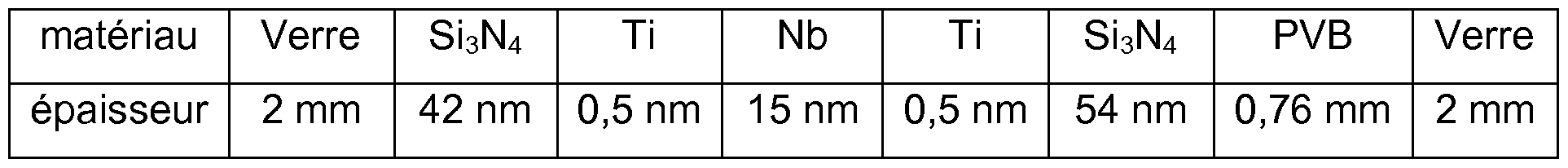
- a heating element according to the invention having the following stack:
- the niobium layer is the layer suitable for heating and the titanium layers are the blocking layers.
- a heating element 1 m high, powered by a voltage of 220 V then dissipates a pfd of 2100 W / m 2 and has a light transmission of 27%.
- Such a heating element can be used as rear side glazing, roof glazing or electric vehicle rear window, or as building glazing or as an electric building radiator.
- a heating element according to the invention having the following stack:
- a heating element 1 m high powered by a voltage of 220 V then dissipates a pfd of 605 W / m 2 and has a light transmission of 50%.
- Such a heating element can be used as rear side glazing, roof glazing or electric vehicle rear window, or as building glazing or as an electric building radiator.
Landscapes
- Engineering & Computer Science (AREA)
- Mechanical Engineering (AREA)
- Surface Heating Bodies (AREA)
- Joining Of Glass To Other Materials (AREA)
- Resistance Heating (AREA)
- Laminated Bodies (AREA)
Abstract
Description


Claims
Priority Applications (9)
| Application Number | Priority Date | Filing Date | Title |
|---|---|---|---|
| CN2012800073247A CN103329616A (zh) | 2011-02-04 | 2012-01-30 | 具有层的加热元件 |
| MX2013008866A MX341630B (es) | 2011-02-04 | 2012-01-30 | Elemento de calentamiento que comprende peliculas. |
| CA2823538A CA2823538A1 (fr) | 2011-02-04 | 2012-01-30 | Element chauffant a couche |
| JP2013552245A JP2014509047A (ja) | 2011-02-04 | 2012-01-30 | フィルムを含む発熱体 |
| EP12706643.9A EP2671424A1 (fr) | 2011-02-04 | 2012-01-30 | Element chauffant a couche |
| EA201391128A EA031947B1 (ru) | 2011-02-04 | 2012-01-30 | Слоистый нагревательный элемент |
| KR1020137020550A KR20140036142A (ko) | 2011-02-04 | 2012-01-30 | 필름을 포함하는 발열 소자 |
| US13/980,228 US10029651B2 (en) | 2011-02-04 | 2012-01-30 | Heating element comprising films |
| BR112013014948A BR112013014948A2 (pt) | 2011-02-04 | 2012-01-30 | elemento aquecedor de camada |
Applications Claiming Priority (2)
| Application Number | Priority Date | Filing Date | Title |
|---|---|---|---|
| FR1150914 | 2011-02-04 | ||
| FR1150914A FR2971387B1 (fr) | 2011-02-04 | 2011-02-04 | Element chauffant a couche |
Publications (1)
| Publication Number | Publication Date |
|---|---|
| WO2012104530A1 true WO2012104530A1 (fr) | 2012-08-09 |
Family
ID=44455576
Family Applications (1)
| Application Number | Title | Priority Date | Filing Date |
|---|---|---|---|
| PCT/FR2012/050184 Ceased WO2012104530A1 (fr) | 2011-02-04 | 2012-01-30 | Element chauffant a couche |
Country Status (11)
| Country | Link |
|---|---|
| US (1) | US10029651B2 (fr) |
| EP (1) | EP2671424A1 (fr) |
| JP (1) | JP2014509047A (fr) |
| KR (1) | KR20140036142A (fr) |
| CN (2) | CN103329616A (fr) |
| BR (1) | BR112013014948A2 (fr) |
| CA (1) | CA2823538A1 (fr) |
| EA (1) | EA031947B1 (fr) |
| FR (1) | FR2971387B1 (fr) |
| MX (1) | MX341630B (fr) |
| WO (1) | WO2012104530A1 (fr) |
Cited By (5)
| Publication number | Priority date | Publication date | Assignee | Title |
|---|---|---|---|---|
| US10434846B2 (en) | 2015-09-07 | 2019-10-08 | Sabic Global Technologies B.V. | Surfaces of plastic glazing of tailgates |
| US10597097B2 (en) | 2015-09-07 | 2020-03-24 | Sabic Global Technologies B.V. | Aerodynamic features of plastic glazing of tailgates |
| US10690314B2 (en) | 2015-09-07 | 2020-06-23 | Sabic Global Technologies B.V. | Lighting systems of tailgates with plastic glazing |
| US11267173B2 (en) | 2015-09-07 | 2022-03-08 | Sabic Global Technologies B.V. | Molding of plastic glazing of tailgates |
| US11466834B2 (en) | 2015-11-23 | 2022-10-11 | Sabic Global Technologies B.V. | Lighting systems for windows having plastic glazing |
Families Citing this family (7)
| Publication number | Priority date | Publication date | Assignee | Title |
|---|---|---|---|---|
| FR2976439A1 (fr) * | 2011-06-07 | 2012-12-14 | Saint Gobain | Element chauffant a couche |
| JP5889404B2 (ja) * | 2011-06-10 | 2016-03-22 | サン−ゴバン グラス フランスSaint−Gobain Glass France | 安全機能を備えた加熱可能な合わせガラス |
| JP6016126B2 (ja) * | 2013-08-07 | 2016-10-26 | 住友電装株式会社 | 電熱線端子への給電線配索構造 |
| FR3020359B1 (fr) * | 2014-04-29 | 2016-05-06 | Eurokera | Plaque en verre partiellement cristallise |
| US11098865B2 (en) | 2020-05-26 | 2021-08-24 | Korea Photonics Technology Institute | Light source, solar cell complex and lighting system including the same |
| CN113038641B (zh) * | 2021-05-17 | 2022-05-13 | 中熵科技(北京)有限公司 | 新型复合半导体制热薄膜及薄膜制备方法 |
| CN118042656B (zh) * | 2024-03-14 | 2024-06-28 | 华中光电技术研究所(中国船舶集团有限公司第七一七研究所) | 一种用于蓝宝石窗口的电加热膜及其制备方法 |
Citations (6)
| Publication number | Priority date | Publication date | Assignee | Title |
|---|---|---|---|---|
| US2852415A (en) * | 1952-10-29 | 1958-09-16 | Libbey Owens Ford Glass Co | Electrically conducting coated glass or ceramic articles suitable for use as a lens, a window or a windshield, or the like |
| DE3418612A1 (de) * | 1983-05-19 | 1984-11-22 | Toyoda Gosei Co., Ltd., Haruhimura, Aichi | Exothermischer transparenter koerper |
| US4952783A (en) * | 1989-03-20 | 1990-08-28 | W. H. Brady Co. | Light transmitting flexible film electrical heater panels |
| JPH0794263A (ja) * | 1993-06-11 | 1995-04-07 | Nippon Sheet Glass Co Ltd | 合せガラス |
| US5750267A (en) * | 1993-01-27 | 1998-05-12 | Mitsui Toatsu Chemicals, Inc. | Transparent conductive laminate |
| GB2361990A (en) * | 2000-05-03 | 2001-11-07 | Jk Microtechnology Ltd | Transparent electric convection heater |
Family Cites Families (21)
| Publication number | Priority date | Publication date | Assignee | Title |
|---|---|---|---|---|
| US3816201A (en) * | 1970-03-26 | 1974-06-11 | Sierracin Corp | Laminated structures and method of forming the same |
| BE787599A (fr) * | 1971-08-16 | 1973-02-16 | Battelle Memorial Institute | Vitrage filtrant antisolaire et isolant thermique |
| US4226910A (en) * | 1979-07-12 | 1980-10-07 | Minnesota Mining And Manufacturing Company | Energy control sheet having insulative properties |
| DE3039821A1 (de) * | 1980-10-22 | 1982-06-03 | Robert Bosch Gmbh, 7000 Stuttgart | Mehrschichtsystem fuer waermeschutzanwendung |
| US4771167A (en) * | 1987-09-14 | 1988-09-13 | Ford Motor Company | Method of increasing the visible transmittance of an electrically heated window and product produced thereby |
| US4976503A (en) * | 1989-07-27 | 1990-12-11 | Monsanto Company | Optical element for a vehicle windshield |
| US5688585A (en) * | 1993-08-05 | 1997-11-18 | Guardian Industries Corp. | Matchable, heat treatable, durable, IR-reflecting sputter-coated glasses and method of making same |
| JP3325361B2 (ja) | 1993-10-15 | 2002-09-17 | 三井化学株式会社 | 透明面状ヒーターおよびその製造方法 |
| JPH07196341A (ja) | 1993-12-28 | 1995-08-01 | Tatsuguchi Kogyo Glass Kk | 除曇ガラス |
| JPH0831555A (ja) | 1994-07-14 | 1996-02-02 | Asahi Glass Co Ltd | 窓ガラス加熱装置 |
| JPH0986975A (ja) | 1995-09-29 | 1997-03-31 | Asahi Glass Co Ltd | 複層ガラス用スペーサの製造方法および複層ガラス |
| CN1158905C (zh) * | 1998-12-25 | 2004-07-21 | 菲格拉株式会社 | 具有发热功能的透光性板材及使用该板材的系统 |
| JP2002134254A (ja) * | 2000-10-30 | 2002-05-10 | Pentel Corp | ヒーター付透明体 |
| US6559419B1 (en) * | 2001-08-03 | 2003-05-06 | Centre Luxembourgeois De Recherches Pour Le Verre Et La Ceramique S.A. (C.R.V.C.) | Multi-zone arrangement for heatable vehicle window |
| US6870134B2 (en) * | 2002-02-01 | 2005-03-22 | Centre Luxembourgeois De Recherches Pour Le Verre Et La Ceramique S.A. (C.R.V.C.) | Heatable vehicle windshield with bus bars including braided and printed portions |
| US6791065B2 (en) * | 2002-07-24 | 2004-09-14 | Ppg Industries Ohio, Inc. | Edge sealing of a laminated transparency |
| FR2845778B1 (fr) * | 2002-10-09 | 2004-12-17 | Saint Gobain | Dispositif electrocommandable du type electroluminescent |
| US20090237782A1 (en) * | 2005-10-26 | 2009-09-24 | Central Glass Company, Limited | Near Infrared Ray Reflective Substrate And Near Infrared Ray Reflective Laminated Glass Employing That Substrate, Near Infrared Ray Reflective Double Layer Glass |
| GB0711628D0 (en) * | 2007-06-18 | 2007-07-25 | Pilkington Group Ltd | A method of production of a bent, coated, laminated glazing, and a resultant glazing |
| US8199264B2 (en) * | 2007-11-26 | 2012-06-12 | Guardian Industries Corp. | Ruggedized switchable glazing comprising a liquid crystal inclusive layer and a multi-layer low-E ultraviolet blocking coating |
| US20100000669A1 (en) * | 2008-06-13 | 2010-01-07 | Tsinghua University | Carbon nanotube heater |
-
2011
- 2011-02-04 FR FR1150914A patent/FR2971387B1/fr not_active Expired - Fee Related
-
2012
- 2012-01-30 WO PCT/FR2012/050184 patent/WO2012104530A1/fr not_active Ceased
- 2012-01-30 CN CN2012800073247A patent/CN103329616A/zh active Pending
- 2012-01-30 EA EA201391128A patent/EA031947B1/ru not_active IP Right Cessation
- 2012-01-30 US US13/980,228 patent/US10029651B2/en not_active Expired - Fee Related
- 2012-01-30 EP EP12706643.9A patent/EP2671424A1/fr not_active Withdrawn
- 2012-01-30 KR KR1020137020550A patent/KR20140036142A/ko not_active Abandoned
- 2012-01-30 JP JP2013552245A patent/JP2014509047A/ja active Pending
- 2012-01-30 MX MX2013008866A patent/MX341630B/es active IP Right Grant
- 2012-01-30 BR BR112013014948A patent/BR112013014948A2/pt not_active Application Discontinuation
- 2012-01-30 CA CA2823538A patent/CA2823538A1/fr not_active Abandoned
- 2012-01-30 CN CN201811275636.1A patent/CN110099466A/zh active Pending
Patent Citations (6)
| Publication number | Priority date | Publication date | Assignee | Title |
|---|---|---|---|---|
| US2852415A (en) * | 1952-10-29 | 1958-09-16 | Libbey Owens Ford Glass Co | Electrically conducting coated glass or ceramic articles suitable for use as a lens, a window or a windshield, or the like |
| DE3418612A1 (de) * | 1983-05-19 | 1984-11-22 | Toyoda Gosei Co., Ltd., Haruhimura, Aichi | Exothermischer transparenter koerper |
| US4952783A (en) * | 1989-03-20 | 1990-08-28 | W. H. Brady Co. | Light transmitting flexible film electrical heater panels |
| US5750267A (en) * | 1993-01-27 | 1998-05-12 | Mitsui Toatsu Chemicals, Inc. | Transparent conductive laminate |
| JPH0794263A (ja) * | 1993-06-11 | 1995-04-07 | Nippon Sheet Glass Co Ltd | 合せガラス |
| GB2361990A (en) * | 2000-05-03 | 2001-11-07 | Jk Microtechnology Ltd | Transparent electric convection heater |
Cited By (13)
| Publication number | Priority date | Publication date | Assignee | Title |
|---|---|---|---|---|
| US11458709B2 (en) | 2015-09-07 | 2022-10-04 | Sabic Global Technologies B.V. | Three shot plastic tailgate |
| US10597097B2 (en) | 2015-09-07 | 2020-03-24 | Sabic Global Technologies B.V. | Aerodynamic features of plastic glazing of tailgates |
| US10690314B2 (en) | 2015-09-07 | 2020-06-23 | Sabic Global Technologies B.V. | Lighting systems of tailgates with plastic glazing |
| US10717348B2 (en) | 2015-09-07 | 2020-07-21 | Sabic Global Technologies B.V. | Surfaces of plastic glazing of tailgates |
| US10948152B2 (en) | 2015-09-07 | 2021-03-16 | Sabic Global Technologies B.V. | Lighting systems of tailgates with plastic glazing |
| US11267173B2 (en) | 2015-09-07 | 2022-03-08 | Sabic Global Technologies B.V. | Molding of plastic glazing of tailgates |
| US10434846B2 (en) | 2015-09-07 | 2019-10-08 | Sabic Global Technologies B.V. | Surfaces of plastic glazing of tailgates |
| US11845240B2 (en) | 2015-09-07 | 2023-12-19 | Sabic Global Technologies B.V. | Three shot plastic tailgate |
| US12330397B2 (en) | 2015-09-07 | 2025-06-17 | Sabic Global Technologies B.V. | Three shot plastic tailgate |
| US12390967B2 (en) | 2015-09-07 | 2025-08-19 | Sabic Global Technologies B.V. | Molding of plastic glazing of tailgates |
| US11466834B2 (en) | 2015-11-23 | 2022-10-11 | Sabic Global Technologies B.V. | Lighting systems for windows having plastic glazing |
| US11766965B2 (en) | 2015-11-23 | 2023-09-26 | Sabic Global Technologies B.V. | Illuminated graphic in an automotive plastic glazing |
| US12145498B2 (en) | 2015-11-23 | 2024-11-19 | Sabic Global Technologies B.V. | Illuminated graphic in an automotive plastic glazing |
Also Published As
| Publication number | Publication date |
|---|---|
| JP2014509047A (ja) | 2014-04-10 |
| US20130299479A1 (en) | 2013-11-14 |
| KR20140036142A (ko) | 2014-03-25 |
| CN110099466A (zh) | 2019-08-06 |
| BR112013014948A2 (pt) | 2016-09-13 |
| FR2971387A1 (fr) | 2012-08-10 |
| EA031947B1 (ru) | 2019-03-29 |
| EP2671424A1 (fr) | 2013-12-11 |
| MX2013008866A (es) | 2013-08-14 |
| CA2823538A1 (fr) | 2012-08-09 |
| CN103329616A (zh) | 2013-09-25 |
| EA201391128A1 (ru) | 2013-12-30 |
| FR2971387B1 (fr) | 2014-08-08 |
| US10029651B2 (en) | 2018-07-24 |
| MX341630B (es) | 2016-08-29 |
Similar Documents
| Publication | Publication Date | Title |
|---|---|---|
| WO2012104530A1 (fr) | Element chauffant a couche | |
| EP2719252A1 (fr) | Element chauffant a couche | |
| EP2127475B1 (fr) | Vitre transparente avec un revêtement chauffant | |
| EP1897412B9 (fr) | Vitrage chauffant feuillete ayant un confort de vision ameliore | |
| EP1803327B1 (fr) | Vitrage transparent avec un revetement chauffant resistif | |
| FR2874100A1 (fr) | Systeme electrochimique comportant au moins une zone de margeage partiel | |
| EP1175813B1 (fr) | Vitrages chauffants, en particulier pour vehicules | |
| EP0394089A2 (fr) | Vitrage automobile chauffable électriquement | |
| US20060186105A1 (en) | Heatable windshield | |
| WO2016012323A1 (fr) | Vitrage chauffant | |
| WO2010138157A1 (fr) | Procédé d'amélioration des propriétés conductrices et optiques de films minces en oxyde d'indium dopé à l'étain (ito) déposés | |
| US20080277320A1 (en) | Vehicle transparency heated with alternating current | |
| WO2019053381A1 (fr) | Vitrage feuillete comprenant un substrat transparent a couche chauffante ayant des lignes d'ablation se refermant chacune sur elle-meme | |
| EP3894220A1 (fr) | Vitrage feuilleté comprenant un substrat transparent a couche chauffante ayant des lignes de flux dont l'ensemble est de largeur variable | |
| CA1337172C (fr) | Vitrage feuillete a couche electro-conductrice | |
| FR2683919A1 (fr) | Structure composite destinee a reflechir ou transmettre la chaleur, ensemble mettant en óoeuvre une telle structure et procede de fabrication d'un tel ensemble. | |
| EP1525777A1 (fr) | Vitrage chauffant |
Legal Events
| Date | Code | Title | Description |
|---|---|---|---|
| 121 | Ep: the epo has been informed by wipo that ep was designated in this application |
Ref document number: 12706643 Country of ref document: EP Kind code of ref document: A1 |
|
| WWE | Wipo information: entry into national phase |
Ref document number: 2012706643 Country of ref document: EP |
|
| ENP | Entry into the national phase |
Ref document number: 2823538 Country of ref document: CA |
|
| WWE | Wipo information: entry into national phase |
Ref document number: 13980228 Country of ref document: US |
|
| WWE | Wipo information: entry into national phase |
Ref document number: MX/A/2013/008866 Country of ref document: MX |
|
| ENP | Entry into the national phase |
Ref document number: 2013552245 Country of ref document: JP Kind code of ref document: A Ref document number: 20137020550 Country of ref document: KR Kind code of ref document: A |
|
| NENP | Non-entry into the national phase |
Ref country code: DE |
|
| WWE | Wipo information: entry into national phase |
Ref document number: 201391128 Country of ref document: EA |
|
| REG | Reference to national code |
Ref country code: BR Ref legal event code: B01A Ref document number: 112013014948 Country of ref document: BR |
|
| ENP | Entry into the national phase |
Ref document number: 112013014948 Country of ref document: BR Kind code of ref document: A2 Effective date: 20130614 |