WO2012104937A1 - Ledモジュールおよび照明装置 - Google Patents
Ledモジュールおよび照明装置 Download PDFInfo
- Publication number
- WO2012104937A1 WO2012104937A1 PCT/JP2011/004779 JP2011004779W WO2012104937A1 WO 2012104937 A1 WO2012104937 A1 WO 2012104937A1 JP 2011004779 W JP2011004779 W JP 2011004779W WO 2012104937 A1 WO2012104937 A1 WO 2012104937A1
- Authority
- WO
- WIPO (PCT)
- Prior art keywords
- light
- phosphor
- color
- green
- less
- Prior art date
- Legal status (The legal status is an assumption and is not a legal conclusion. Google has not performed a legal analysis and makes no representation as to the accuracy of the status listed.)
- Ceased
Links
Images



Classifications
-
- H—ELECTRICITY
- H10—SEMICONDUCTOR DEVICES; ELECTRIC SOLID-STATE DEVICES NOT OTHERWISE PROVIDED FOR
- H10H—INORGANIC LIGHT-EMITTING SEMICONDUCTOR DEVICES HAVING POTENTIAL BARRIERS
- H10H20/00—Individual inorganic light-emitting semiconductor devices having potential barriers, e.g. light-emitting diodes [LED]
- H10H20/80—Constructional details
- H10H20/85—Packages
- H10H20/851—Wavelength conversion means
- H10H20/8511—Wavelength conversion means characterised by their material, e.g. binder
- H10H20/8512—Wavelength conversion materials
- H10H20/8513—Wavelength conversion materials having two or more wavelength conversion materials
-
- F—MECHANICAL ENGINEERING; LIGHTING; HEATING; WEAPONS; BLASTING
- F21—LIGHTING
- F21K—NON-ELECTRIC LIGHT SOURCES USING LUMINESCENCE; LIGHT SOURCES USING ELECTROCHEMILUMINESCENCE; LIGHT SOURCES USING CHARGES OF COMBUSTIBLE MATERIAL; LIGHT SOURCES USING SEMICONDUCTOR DEVICES AS LIGHT-GENERATING ELEMENTS; LIGHT SOURCES NOT OTHERWISE PROVIDED FOR
- F21K9/00—Light sources using semiconductor devices as light-generating elements, e.g. using light-emitting diodes [LED] or lasers
- F21K9/20—Light sources comprising attachment means
- F21K9/23—Retrofit light sources for lighting devices with a single fitting for each light source, e.g. for substitution of incandescent lamps with bayonet or threaded fittings
- F21K9/232—Retrofit light sources for lighting devices with a single fitting for each light source, e.g. for substitution of incandescent lamps with bayonet or threaded fittings specially adapted for generating an essentially omnidirectional light distribution, e.g. with a glass bulb
-
- F—MECHANICAL ENGINEERING; LIGHTING; HEATING; WEAPONS; BLASTING
- F21—LIGHTING
- F21K—NON-ELECTRIC LIGHT SOURCES USING LUMINESCENCE; LIGHT SOURCES USING ELECTROCHEMILUMINESCENCE; LIGHT SOURCES USING CHARGES OF COMBUSTIBLE MATERIAL; LIGHT SOURCES USING SEMICONDUCTOR DEVICES AS LIGHT-GENERATING ELEMENTS; LIGHT SOURCES NOT OTHERWISE PROVIDED FOR
- F21K9/00—Light sources using semiconductor devices as light-generating elements, e.g. using light-emitting diodes [LED] or lasers
- F21K9/20—Light sources comprising attachment means
- F21K9/27—Retrofit light sources for lighting devices with two fittings for each light source, e.g. for substitution of fluorescent tubes
-
- F—MECHANICAL ENGINEERING; LIGHTING; HEATING; WEAPONS; BLASTING
- F21—LIGHTING
- F21K—NON-ELECTRIC LIGHT SOURCES USING LUMINESCENCE; LIGHT SOURCES USING ELECTROCHEMILUMINESCENCE; LIGHT SOURCES USING CHARGES OF COMBUSTIBLE MATERIAL; LIGHT SOURCES USING SEMICONDUCTOR DEVICES AS LIGHT-GENERATING ELEMENTS; LIGHT SOURCES NOT OTHERWISE PROVIDED FOR
- F21K9/00—Light sources using semiconductor devices as light-generating elements, e.g. using light-emitting diodes [LED] or lasers
- F21K9/60—Optical arrangements integrated in the light source, e.g. for improving the colour rendering index or the light extraction
- F21K9/64—Optical arrangements integrated in the light source, e.g. for improving the colour rendering index or the light extraction using wavelength conversion means distinct or spaced from the light-generating element, e.g. a remote phosphor layer
-
- F—MECHANICAL ENGINEERING; LIGHTING; HEATING; WEAPONS; BLASTING
- F21—LIGHTING
- F21V—FUNCTIONAL FEATURES OR DETAILS OF LIGHTING DEVICES OR SYSTEMS THEREOF; STRUCTURAL COMBINATIONS OF LIGHTING DEVICES WITH OTHER ARTICLES, NOT OTHERWISE PROVIDED FOR
- F21V3/00—Globes; Bowls; Cover glasses
-
- F—MECHANICAL ENGINEERING; LIGHTING; HEATING; WEAPONS; BLASTING
- F21—LIGHTING
- F21Y—INDEXING SCHEME ASSOCIATED WITH SUBCLASSES F21K, F21L, F21S and F21V, RELATING TO THE FORM OR THE KIND OF THE LIGHT SOURCES OR OF THE COLOUR OF THE LIGHT EMITTED
- F21Y2103/00—Elongate light sources, e.g. fluorescent tubes
- F21Y2103/10—Elongate light sources, e.g. fluorescent tubes comprising a linear array of point-like light-generating elements
-
- F—MECHANICAL ENGINEERING; LIGHTING; HEATING; WEAPONS; BLASTING
- F21—LIGHTING
- F21Y—INDEXING SCHEME ASSOCIATED WITH SUBCLASSES F21K, F21L, F21S and F21V, RELATING TO THE FORM OR THE KIND OF THE LIGHT SOURCES OR OF THE COLOUR OF THE LIGHT EMITTED
- F21Y2115/00—Light-generating elements of semiconductor light sources
- F21Y2115/10—Light-emitting diodes [LED]
-
- H—ELECTRICITY
- H10—SEMICONDUCTOR DEVICES; ELECTRIC SOLID-STATE DEVICES NOT OTHERWISE PROVIDED FOR
- H10W—GENERIC PACKAGES, INTERCONNECTIONS, CONNECTORS OR OTHER CONSTRUCTIONAL DETAILS OF DEVICES COVERED BY CLASS H10
- H10W90/00—Package configurations
Definitions
- the present invention relates to a high-saturation LED (Light Emitting Diode) module and an illumination device that can improve the vividness of the color of an illuminated object.
- a high-saturation LED Light Emitting Diode
- Patent Document 1 presupposes a lamp for general illumination (see paragraph 0002).
- the application range of LED lamps will expand, and may be applied to product display lamps such as lamps provided in showcases. is assumed.
- LED lamps that have improved color rendering using the technology of Patent Document 1 or the like that is, LED lamps having a high color rendering index Ra, emit light in the yellow region of the emission spectrum of LEDs. Vivid colors of foods and articles may appear yellowish or dull as a whole due to the influence of a large amount of components, and as a result, color reproduction may not be preferable.
- an object of the present invention is to provide a high-saturation LED module and an illumination device that can improve the vividness of the color of an illuminated object even when the color temperature of ambient light is high, and as a result, can preferably reproduce the color.
- An LED module includes a blue LED that emits blue light, a green phosphor that absorbs part of the emitted light from the blue LED and emits green light, a part of the emitted light from the blue LED, and A red phosphor that absorbs at least one part of the emitted light of the green phosphor and emits red light, and the peak wavelength of the emission spectrum of the blue LED is 420 nm to 470 nm,
- the full width at half maximum is greater than 0 nm to 50 nm or less
- the peak wavelength of the emission spectrum of the green phosphor is from 500 nm to 535 nm
- the half width is from 100 nm to 110 nm
- the emission spectrum has a peak wavelength of 610 nm to 670 nm or less, a half width of 85 nm to 95 nm, and a correlated color temperature Tc of the mixed light of the blue light, the green light, and the red light is 4600.
- the lighting device according to the present invention has the same configuration as the LED module.
- duv Distance from perfect radiator locus on uv-ordinates
- ⁇ uv chromaticity deviation
- the correlation color temperature Tc in the above configuration is 4600K or more and 7200K or less corresponds to the range of daylight color (4600K or more and 5500K or less) to daylight color (5700K or more and 7100K or less) specified in Japanese Industrial Standard JIS ⁇ Z9112. That is, the correlated color temperature of the mixed color light is high. Further, duv is -12 or more and -6 or less, on the xy chromaticity diagram, corresponds to a range below the chromaticity range of the light source color defined in the same standard (that is, y value is small), This means that the reddish component contained in the mixed color light increases, and as a result, the saturation increases.
- the saturation can be improved by limiting the peak wavelength and half-value width of each of the red phosphor and the green phosphor to a specific range. Due to the synergistic effect of such conditions, even when the correlated color temperature of ambient light is high, it is possible to improve the vividness of the color of the illuminated object, and as a result, it is possible to realize a high-saturation LED module that can preferably reproduce colors.
- Sectional drawing which shows the structure of the LED module which concerns on embodiment of this invention
- Xy chromaticity diagram for explaining a chromaticity range of an LED module according to an embodiment of the present invention
- Diagram showing U * V * uniform color space for sample with color temperature Tc of 6200K and duv of -10
- the figure which shows an example of the data of color gamut area ratio Ga Figure illustrating the range that satisfies Equation 1 when duv is fixed
- the figure which illustrates the structure of an illuminating device The figure which illustrates the structure of an illuminating device
- Fig.1 (a) is sectional drawing which shows the structure of the LED module which concerns on embodiment of this invention.
- the LED module 11 includes a package base 12, a lead 13, a blue LED 14, a transparent sealing material 15, a green phosphor 16, and a red phosphor 17.
- the package base 12 is made of an insulating material such as ceramics
- the lead 13 is made of a conductive material such as metal
- the transparent sealing material 15 is made of a transparent material such as silicone.
- the blue LED 14 emits blue light by the power supplied through the lead 13.
- An example of such an LED is a gallium nitride LED.
- the green phosphor 16 absorbs a part of the light emitted from the blue LED 14 and emits green light.
- An example of such a phosphor is a YAG phosphor.
- the YAG phosphor for example, (Y 1-x Ce x ) 3 (Al 1-y Ga y) 5 O 12, however, make use of 0.01 ⁇ x ⁇ 5,0 ⁇ y ⁇ 5, However, other known ones may be used.
- the red phosphor 17 absorbs at least one of part of the emitted light from the blue LED 14 and part of the emitted light from the green phosphor 16 and emits red light.
- An example of such a phosphor is CASN phosphor.
- CASN phosphor for example, (Sr 1-x Ca x ) AlSiN 3 : Eu 2+ , where 0 ⁇ x ⁇ 1, can be used. Good.
- the blue LED 14 is covered with the transparent sealing material 15, and the green phosphor 16 and the red phosphor 17 are dispersed in the transparent sealing material 15. Therefore, the light emitted from the LED module 11 is a mixed color light of blue light, green light, and red light.
- the color temperature and chromaticity range of the mixed color light are adjusted by adjusting the total amount of the green phosphor 16 and the red phosphor 17 per blue LED 14 and the mixing ratio of the green phosphor 16 and the red phosphor 17. Can be set as appropriate.
- the peak wavelengths and the half-value widths of the emission spectra of the blue LED, the green phosphor and the red phosphor are within the following ranges.
- the color temperature Tc of the mixed color light and its duv are adjusted so as to be within the following ranges.
- Blue LED Peak wavelength 420nm to 470nm Half width greater than 0nm to 50nm or less
- Green phosphor Peak wavelength 500nm to 535nm Half width 100nm to 110nm
- Red phosphor Peak wavelength 610nm to 670nm Half width 85nm to 95nm
- Mixed color light Color temperature Tc 4600K or more and 7200K or less duv -12 or more and -6 or less
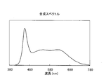
- FIG. 3 shows the measurement results of the emission spectra of these mixed color lights.
- Various characteristics obtained from these are as follows. Various characteristics obtained from the measurement results are all within the target range. Therefore, it has been shown that an LED module within the above range can actually be manufactured.
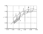
- FIG. 4 is an xy chromaticity diagram for explaining a chromaticity range of the LED module according to the embodiment of the present invention.
- a region A in the figure is the chromaticity range of the mixed color light of the present embodiment.
- Figure 4 shows the light bulb color L (2600K to 3250K), warm white WW (3250K to 3800K), white W (3800K to 4500K), day white N (4600K) as defined in Japanese Industrial Standard JIS Z9112.
- the chromaticity range of daylight color D (5700K or more and 7100K or less) is also shown.
- the chromaticity range of the mixed light according to the present embodiment is such that the color temperature Tc is 4600K or more and 7200K or less, and corresponds to the range of daylight white N to daylight color D. That is, the color temperature of the mixed color light is high. Further, since the duv of the mixed color light in the present embodiment is -12 or more and -6 or less, the xy chromaticity diagram has a lower range than the chromaticity range of the light source color defined in the same standard. The mixed color light under this condition has a lot of redness components included in the chromaticity range of JISZ9112, which means that color reproducibility is improved.
- a highly saturated LED module can be realized.
- the range of duv of mixed color light in this embodiment is determined using the isochromaticity region defined by MacAdam. Therefore, if it is in the range of the region A in FIG. 4, it can be said that the light color is almost equivalent, and the desired effect can be obtained.
- the definition of the isochromaticity region is described in, for example, Color Science Handbook, 2nd edition, page 273.
- the LED module capable of realizing high saturation has been described, but higher saturation may be required in some cases.
- an LED module capable of realizing further high saturation will be described.
- the color gamut area ratio Ga which is an index that quantitatively shows the color vividness of the illuminated object, will be described, and then, to achieve the high saturation obtained by using the color gamut area ratio Ga. Means will be described. Since the structure of the LED module itself is the same as described above, description thereof is omitted.
- the color gamut area ratio Ga is described in JIS Z8726-1990, and the calculation method is as follows.
- the reference light source is black body radiation having the same correlated color temperature as the sample light source, or CIE daylight.
- the test colors numbered 1 to 8 used to calculate the color gamut area ratio Ga have various hues, and their Munsell lightness is all 6. This is a color sample with medium vividness. Therefore, the color gamut area ratio Ga is used as an index of average vividness for all colors.
- the color gamut area ratio Ga is less than 100, the saturation tends to decrease, so the color tends to look dull.
- the color gamut area ratio Ga is greater than 100, the saturation tends to increase, so the color tends to look vivid. It is in. Since general object colors generally feel finer as the saturation appears to increase, it is effective to use the color gamut area ratio Ga as an index for evaluating whether the color looks preferable.
- FIG. 5 shows a U * V * uniform color space for a sample having a color temperature Tc of 6200K and a duv of -10.
- the color gamut area ratio Ga at this time was 105.
- the blue LED, green phosphor and red phosphor are the same as those already described. That is, the peak wavelength of the green phosphor is 500 nm to 535 nm, and the peak wavelength of the red phosphor is 610 nm to 670 nm.
- the green is 520nm and is red in the middle 640nm intermediate, i.e., a data of the case where the difference [Delta] [lambda] R-G a moderate 120 nm.
- Figure 6 (d) green is is red minimum 610nm minimum 520 nm, that is, data of the case where the difference [Delta] [lambda] R-G a moderate 110 nm.
- FIG. 6 (e) green is the smallest 500nm red is the largest 670 nm, that is, data of the case where the difference [Delta] [lambda] R-G is the maximum of 170 nm.
- the color gamut area ratio Ga is less than 100 in only four examples. In all other cases, the color gamut area ratio Ga is 100 or more, so that high saturation can be realized. The inventors have found that the color gamut area ratio Ga is 100 or more using the enormous amount of the obtained data of the color gamut area ratio Ga when the following condition is satisfied. .
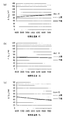
- FIGS. 7A to 7C show ⁇ RB with respect to the color temperature Tc when duv is fixed to ⁇ 6, ⁇ 9, and ⁇ 12, respectively, and the ranges satisfying the following formulas 2 to 4 Is shown.
- FIGS. 8A to 8C show ⁇ RB with respect to duv when the color temperature Tc is fixed to 4600K, 6000K, and 7200K, respectively. The ranges satisfying the following expressions 5 to 7 are satisfied. Show.
- the color gamut area ratio Ga can be increased to 100 or more by adjusting the color temperature and chromaticity range of the mixed color light so as to satisfy the formula 1, and as a result, an LED module with higher saturation can be obtained. Can be realized.
- ⁇ Supplement> 1 Structure of LED Module
- the structure of the LED module has been described with reference to FIG. 1A.
- the present invention is not limited as long as it includes a blue LED, a green phosphor, and a red phosphor.
- the structure can also be applied.
- the one shown in FIG. 1B includes a circuit board 22, a wiring pattern 23, a blue LED 24, a transparent sealing material 25, a green phosphor 26, and a red phosphor 27.
- a bullet-type LED module may be used.
- Lighting device A The LED module can be applied to a lighting device as shown below.
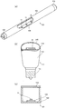
- FIG. 9A shows an example in which the LED module 11 is applied to a straight tube type lighting device 101.
- the lighting device 101 includes a straight tubular transparent member 102, a base 103, a substrate 104, and an LED module 11.
- a straight tube type is used, but it is naturally applicable to a circular tube type.
- FIG. 9B shows an example in which the LED module 21 is applied to a light bulb-shaped illumination device 111.
- the lighting device 111 includes a body 112, a base 113, a substrate 114, a globe 115, and an LED module 21.
- FIG. 9C shows an example in which the LED module 11 is applied to a cylindrical illumination device 121.
- the lighting device 121 includes a cylindrical casing 122, a substrate 123, a transparent member 124, and the LED module 11.
- Lighting device B Although the said illuminating device applies the LED module which radiate
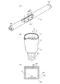
- FIG. 10A shows an example in which the LED module 31 that emits blue light is applied to the straight tube type illumination device 201.
- the lighting device 201 includes a straight tubular transparent member 102, a base 103, a substrate 104, a phosphor layer 202, and an LED module 31.
- the phosphor layer 202 includes a green phosphor and a red phosphor, and is formed on the inner surface of the transparent member 102.
- the phosphor layer 202 is not limited to the inner surface of the transparent member 102 and may be formed on the outer surface. Further, the transparent member 102 itself may include a green phosphor and a red phosphor.
- FIG. 10B shows an example in which the LED module 41 that emits blue light is applied to the light bulb-shaped illumination device 211.
- the lighting device 211 includes a body 112, a base 113, a substrate 114, a globe 115, a phosphor layer 212, and an LED module 41.
- the phosphor layer 212 includes a green phosphor and a red phosphor, and is formed on the inner surface of the globe 115.
- the phosphor layer 212 is not limited to the inner surface of the globe 115 and may be formed on the outer surface.
- the globe 115 itself may include a green phosphor and a red phosphor.
- FIG. 10C shows an example in which the LED module 31 is applied to a cylindrical illumination device 221.
- the lighting device 221 includes a cylindrical casing 122, a substrate 123, a transparent member 124, a phosphor layer 222, and an LED module 31.
- the phosphor layer 222 includes a green phosphor and a red phosphor, and is formed on the inner surface of the transparent member 124.
- the phosphor layer 222 is not limited to the inner surface of the transparent member 124 but may be formed on the outer surface. Further, the transparent member 124 itself may include a green phosphor and a red phosphor.
- the lighting device can be applied to, for example, a product display lamp.
- the lamps for displaying merchandise include lamps built in merchandise display devices such as showcases, and lamps provided on ceiling surfaces, wall surfaces, and shelves of stores and warehouses.
- the LED module is also suitable for producing spot light, it can be substituted for a field in which a halogen lamp with a reflector has been conventionally used.
- the present invention can be used for a lamp.
- LED module 12 Package base 13 Lead 14 Blue LED DESCRIPTION OF SYMBOLS 15 Transparent sealing material 16 Green fluorescent substance 17 Red fluorescent substance 21 LED module 22 Circuit board 23 Wiring pattern 24 Blue LED 25 Transparent sealing material 26 Green phosphor 27 Red phosphor 31 LED module 41 LED module 101 Illumination device 102 Transparent member 103 Base 104 Substrate 111 Illumination device 112 Body 113 Base 114 Substrate 115 Globe 121 Illumination device 122 Housing 123 Substrate 124 Transparent Member 201 Illuminating device 202 Phosphor layer 211 Illuminating device 212 Phosphor layer 221 Illuminating device 222 Phosphor layer
Landscapes
- Led Device Packages (AREA)
- Engineering & Computer Science (AREA)
- General Engineering & Computer Science (AREA)
Abstract
環境光の色温度が高い場合でも、照明された物体の色の鮮やかさを改善し、結果好ましく色再現できる高彩度のLEDモジュールおよび照明装置を提供する。 青色LEDの発光スペクトルのピーク波長が420 nm以上470 nm以下であり、その半値幅が0 nmより大きく50 nm以下である。緑色蛍光体の発光スペクトルのピーク波長が500 nm以上535 nm以下であり、その半値幅が100 nm以上110 nm以下である。赤色蛍光体の発光スペクトルのピーク波長が610 nm以上670 nm以下であり、その半値幅が85 nm以上95 nm以下である。青色光と緑色光と赤色光の混色光の相関色温度Tcが4600 K以上7200 K以下であり、そのduvが-12以上-6以下である。
Description
本発明は、照明された物体の色の鮮やかさを改善できる高彩度のLED(Light Emitting Diode)モジュールおよび照明装置に関する。
近年、LEDモジュールを採用したLEDランプ等の照明装置が普及してきている。一般照明用のランプには、光に照らされた物体の色が好ましく見えることが望まれている。一般的に、各種光源による色の見え方の良否は、演色評価指数で定量的に評価する方法、すなわち“演色性”の評価が確立されている。これは対象とする光が基準光にくらべてどの程度忠実に色を再現しているかを定量評価するものである。この“演色性”の評価方法に則り、演色性を高める技術が種々提案されており、その一つに、LEDに組み合わせる蛍光体の色の種類を増やすという技術がある。例えば、特許文献1には、従来の蛍光体に加えて赤色蛍光体を配合することが記載されている(段落0007参照)。
特許文献1では一般照明用のランプを前提としているが(段落0002参照)、今後、LEDランプの適用範囲が広がり、ショーケースに設けられるランプのような商品展示用のランプに適用されることも想定される。しかしながら、特許文献1等の技術を用いて演色性を高めたLEDランプ、すなわち高い演色評価指数Raを有するLEDランプであっても、商品展示用途においては、LEDの発光スペクトルのうち黄色領域の発光成分が多い等の影響により食品や物品等の鮮やかな色彩が全体的に黄ばんだりくすんで見え、結果好ましく色再現できないことがある。
加えて、上記用途に特許文献1の技術を適用した場合、赤色蛍光体の追加的な配合により演色性を高めたLEDランプを実現することができるが、赤色蛍光体の追加は必然的にランプの相関色温度(以下、単に「色温度」という場合がある)を低下させることになり、より高い効果を得ようとすると、色温度の低いランプしか得ることができない。しかし、最近のショーケースが置かれる光環境を見ると、店舗や倉庫等の室内において色温度の高い室内照明のもとに置かれる場合も増えている。このような状況において、ショーケース内のLEDランプの色温度が低いと、LEDランプに照らされた商品の見え方に黄ばみ等の色の鮮やかさを低下させる現象が生じる。近年、室内照明等の環境光の色温度は高くなる傾向にあり、今後、環境光の色温度が高い状況下で商品展示用のLEDランプが利用される機会が増えると考えられる。
そこで、本発明は、環境光の色温度が高い場合でも、照明された物体の色の鮮やかさを改善し、結果好ましく色再現できる高彩度のLEDモジュールおよび照明装置を提供することを目的とする。
本発明に係るLEDモジュールは、青色光を出射する青色LEDと、前記青色LEDの出射光の一部を吸収して緑色光を出射する緑色蛍光体と、前記青色LEDの出射光の一部および前記緑色蛍光体の出射光の一部の少なくとも一方を吸収して赤色光を出射する赤色蛍光体と、を備え、前記青色LEDの発光スペクトルのピーク波長が420 nm以上470 nm以下であり、その半値幅が0 nmより大きく50 nm以下であり、前記緑色蛍光体の発光スペクトルのピーク波長が500 nm以上535 nm以下であり、その半値幅が100 nm以上110 nm以下であり、前記赤色蛍光体の発光スペクトルのピーク波長が610 nm以上670 nm以下であり、その半値幅が85 nm以上95 nm以下であり、前記青色光と前記緑色光と前記赤色光の混色光の相関色温度Tcが4600 K以上7200 K以下であり、そのduvが-12以上-6以下である。
本発明に係る照明装置は、上記LEDモジュールと同様の構成を備える。
なお、duv(Distance from perfect radiator locus on uv-ordinates)とは、CIE1960uv色度図上における光色の黒体放射軌跡からのずれである色度偏差(Δuv)を1000倍したものであり、色度図上で色度偏差が黒体放射軌跡の上方にあるときをプラス側とし、下側にあるときにはマイナスの符号をつけて表すものである。
上記構成での相関色温度Tcが4600K以上7200K以下というのは、日本工業規格JIS Z9112に規定された昼白色(4600K以上5500K以下)から昼光色(5700K以上7100K以下)の範囲に相当する。即ち、混色光の相関色温度が高いことを意味する。また、duvが-12以上-6以下というのは、xy色度図上では、同規格に規定された光源色の色度範囲よりも下方(即ち、y値が小さい)の範囲に相当し、混色光に含まれる赤み成分が多くなり、その結果、彩度が高まることを意味する。また、このモジュールを作製するにあたり、赤色蛍光体、緑色蛍光体それぞれのピーク波長および半値幅を特定の範囲に限定することで彩度を向上させることができる。このような条件の相乗効果により、環境光の相関色温度が高い場合でも、照明された物体の色の鮮やかさを改善し、結果好ましく色再現できる高彩度のLEDモジュールを実現することができる。
本発明を実施するための形態を、図面を参照して詳細に説明する。
<構成>
図1(a)は、本発明の実施形態に係るLEDモジュールの構造を示す断面図である。
図1(a)は、本発明の実施形態に係るLEDモジュールの構造を示す断面図である。
LEDモジュール11は、パッケージ基台12、リード13、青色LED14、透明封止材15、緑色蛍光体16および赤色蛍光体17を備える。パッケージ基台12は、セラミックス等の絶縁材料からなり、リード13は、金属等の導電材料からなり、透明封止材15は、シリコーン等の透明材料からなる。
青色LED14は、リード13を通じて供給された電力により青色光を出射する。このようなLEDとしては、例えば、窒化ガリウム系のLEDが挙げられる。
緑色蛍光体16は、青色LED14の出射光の一部を吸収して緑色光を出射する。このような蛍光体としては、例えば、YAG蛍光体がある。YAG蛍光体としては、例えば、(Y1-xCex)3(Al1-yGay)5O12 、ただし、0.01≦x≦5、0≦y≦5、を利用することができるが、これ以外の公知のものを利用してもよい。
赤色蛍光体17は、青色LED14の出射光の一部および緑色蛍光体16の出射光の一部の少なくとも一方を吸収して赤色光を出射する。このような蛍光体としては、例えば、CASN蛍光体がある。CASN蛍光体としては、例えば、(Sr1-xCax)AlSiN3:Eu2+ 、ただし、0≦x≦1、を利用することができるが、これ以外の公知のものを利用してもよい。
LEDモジュール11では、青色LED14が透明封止材15で被覆され、透明封止材15内に緑色蛍光体16および赤色蛍光体17が分散されている。そのため、LEDモジュール11の出射光は、青色光と緑色光と赤色光の混色光となる。混色光の色温度や色度範囲は、青色LED14ひとつ当たりの緑色蛍光体16および赤色蛍光体17の合計の量、および、緑色蛍光体16と赤色蛍光体17との混合比を調整することにより、適宜設定することができる。
<高彩度>
以下、高彩度を実現するための手段について説明する。本実施形態では、青色LED、緑色蛍光体および赤色蛍光体のそれぞれの発光スペクトルのピーク波長およびその半値幅は以下の範囲内にある。さらに、本実施形態では、混色光の色温度Tcとそのduvが以下の範囲内となるように調整されている。
以下、高彩度を実現するための手段について説明する。本実施形態では、青色LED、緑色蛍光体および赤色蛍光体のそれぞれの発光スペクトルのピーク波長およびその半値幅は以下の範囲内にある。さらに、本実施形態では、混色光の色温度Tcとそのduvが以下の範囲内となるように調整されている。
青色LED:ピーク波長 420nm以上470nm以下 半値幅 0nmより大きく50nm以下
緑色蛍光体:ピーク波長 500nm以上535nm以下 半値幅 100nm以上110nm以下
赤色蛍光体:ピーク波長 610nm以上670nm以下 半値幅 85nm以上95nm以下
混色光:色温度Tc 4600K以上7200K以下 duv -12以上-6以下
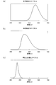
発明者らは、実際にサンプルを作製し、その発光スペクトルを測定した。図2(a)は、赤色蛍光体の発光スペクトルの測定結果、図2(b)は、緑色蛍光体の発光スペクトルの測定結果、図2(c)は、青色LEDの発光スペクトルの測定結果を示す。また、図3は、これらの混色光の発光スペクトルの測定結果を示す。これらから得られた各種特性は、以下の通りである。測定結果から得られた各種特性は、何れも目的の範囲内に収まっている。したがって、実際に上記の範囲内のLEDモジュールが作製可能であることが示されている。
青色LED:ピーク波長450nm 半値幅25nm
緑色蛍光体:ピーク波長525nm 半値幅104nm
赤色蛍光体:ピーク波長645nm 半値幅91nm
混色光:色温度6200K duv-10
図4は、本発明の実施形態に係るLEDモジュールの色度範囲を説明するためのxy色度図である。図中の領域Aが本実施形態の混色光の色度範囲である。なお、図4には、日本工業規格 JIS Z9112に規定された電球色L(2600K以上3250K以下)、温白色WW(3250K以上3800K以下)、白色W(3800K以上4500K以下)、昼白色N(4600K以上5500K以下)、昼光色D(5700K以上7100K以下)の色度範囲も併記してある。
緑色蛍光体:ピーク波長525nm 半値幅104nm
赤色蛍光体:ピーク波長645nm 半値幅91nm
混色光:色温度6200K duv-10
図4は、本発明の実施形態に係るLEDモジュールの色度範囲を説明するためのxy色度図である。図中の領域Aが本実施形態の混色光の色度範囲である。なお、図4には、日本工業規格 JIS Z9112に規定された電球色L(2600K以上3250K以下)、温白色WW(3250K以上3800K以下)、白色W(3800K以上4500K以下)、昼白色N(4600K以上5500K以下)、昼光色D(5700K以上7100K以下)の色度範囲も併記してある。
このように、本実施形態の混色光の色度範囲は、色温度Tcが4600K以上7200K以下であり、昼白色Nから昼光色Dの範囲に相当する。即ち、混色光の色温度が高いことを意味する。また、本実施形態の混色光のduvは、-12以上-6以下なので、xy色度図上では、同規格に規定された光源色の色度範囲よりも下方の範囲になる。この条件での混色光は、JISZ9112の色度範囲に含まれる赤み成分が多く、それにより色再現性が高められることを意味する。このように、混色光の色温度を高めた上で赤み成分を多くすることにより、環境光の色温度が高い場合でも、照明された物体の色の鮮やかさを改善し、結果好ましく色再現できる高彩度のLEDモジュールを実現することができる。
なお、本実施形態の混色光のduvの範囲は、MacAdamにより定義された等色度領域を利用して定めてある。そのため、図4中の領域Aの範囲であれば、光色としてほぼ等価であるといえ、目的の効果を得ることができる。等色度領域の定義については、例えば、色彩科学ハンドブック 第2版 273頁に説明がある。
以上、高彩度を実現できるLEDモジュールについて説明してきたが、さらに高彩度であることも要求される場合がある。以下、更なる高彩度を実現できるLEDモジュールについて説明する。
<更なる高彩度>
最初に、照明された物体の色の鮮やかさを定量的に示す指標である色域面積比Gaについて説明し、次に、色域面積比Gaを利用して得られた高彩度を実現するための手段について説明する。なお、LEDモジュールの構造自体は上記と同様なので説明を省略する。
最初に、照明された物体の色の鮮やかさを定量的に示す指標である色域面積比Gaについて説明し、次に、色域面積比Gaを利用して得られた高彩度を実現するための手段について説明する。なお、LEDモジュールの構造自体は上記と同様なので説明を省略する。
(色域面積比Ga)
色域面積比Gaは、JIS Z8726-1990に記載されており、その算出方法は、次の通りである。
色域面積比Gaは、JIS Z8726-1990に記載されており、その算出方法は、次の通りである。
平均演色表価数Raを算出する際に使用する番号1~8の8つの試験色を基準光源で照明したときに見える色をCIE1964 U*V*均等色空間上にプロットする。そして、これにより得られた8角形の面積を求める。
次に、番号1~8の8つの試験色を試料光源で照明したときに見える色をCIE1964 U*V*均等色空間上にプロットする。そして、これにより得られた8角形の面積を求める。
最後に、色域面積比Gaを、Ga=(試料光源がつくる8角形の面積)/(基準光源がつくる8角形の面積)×100の計算式により算出する。
ここで基準光源とは、試料光源と同じ相関色温度の黒体放射、もしくは、CIE昼光である。色域面積比Gaを算出するのに用いられる番号1~8の試験色は、いろいろな色相を持ち、そのマンセル明度はすべて6である。これは中程度の鮮やかさを持つ色サンプルである。そのため、色域面積比Gaはすべての色に対する平均的な鮮やかさの指標として用いられる。色域面積比Gaが100より小さいときには、彩度が減じる方向にあるので、色がくすんで見える傾向にあり、100より大きいときには、彩度が増加する方向にあるので、色が鮮やかに見える傾向にある。一般の物体色は、概して彩度が増して見えるほどきれいに感じられるので、色が好ましく見えるかを評価する指標として色域面積比Gaを用いることは有効である。
一例として、図5に、色温度Tcが6200K、duvが-10のサンプルについてのU*V*均等色空間を示す。このときの色域面積比Gaは、105であった。
(更なる高彩度の実現手段)
次に、高彩度のLEDモジュールを実現するための手段について説明する。青色LED、緑色蛍光体および赤色蛍光体は、既に説明したものと同じものを使うものとする。即ち、緑色蛍光体のピーク波長は500nm以上535nm以下であり、赤色蛍光体のピーク波長は610nm以上670nm以下である。
次に、高彩度のLEDモジュールを実現するための手段について説明する。青色LED、緑色蛍光体および赤色蛍光体は、既に説明したものと同じものを使うものとする。即ち、緑色蛍光体のピーク波長は500nm以上535nm以下であり、赤色蛍光体のピーク波長は610nm以上670nm以下である。
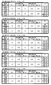
発明者らは、緑色蛍光体のピーク波長と赤色蛍光体のピーク波長の差ΔλR-Gと、色温度Tcと、duvとを変化させたときの色域面積比Gaを算出した。具体的には、ΔλR-Gは、最小の75nmから最大の170nmまでを5nmピッチで区切り、色温度Tcは、最小の4600Kから7200Kまでを100Kピッチで区切り、duvは最小の-12から最大の-6までを1ピッチで区切り、これらで区切られた各点の色域面積比Gaを算出した。そして、色域面積比Gaが100以上であれば、高彩度が実現できる例であると判定した。このようにして得られた色域面積比Gaのデータは膨大な量であり、得られたデータの全てを本明細書に記載するのは現実的ではない。図6に、色域面積比Gaのデータのごく一部を示すこととする。
図6(a)は、緑色が最大の535nmであり赤色が最小の610nmである、即ち、差ΔλR-Gが最小の75nmとなるケースのデータである。例えば、色温度Tcが4600K、duvが-6、赤色蛍光体のピーク波長が610nm、その半値幅が91nm、緑色蛍光体のピーク波長が535nm、その半値幅が104nmの場合、色域面積比Gaが97.5であることを示している。
図6(b)は、緑色が最大の535nmであり赤色が最大の670nmである、即ち、差ΔλR-Gが中程度の135nmとなるケースのデータである。
図6(c)は、緑色が中間の520nmであり赤色が中間の640nmである、即ち、差ΔλR-Gが中程度の120nmとなるケースのデータである。
図6(d)は、緑色が最小の520nmであり赤色が最小の610nmである、即ち、差ΔλR-Gが中程度の110nmとなるケースのデータである。
図6(e)は、緑色が最小の500nmであり赤色が最大の670nmである、即ち、差ΔλR-Gが最大の170nmとなるケースのデータである。
図6に示した例の中では、図6(a)の中に4つの例だけ色域面積比Gaが100未満となるものがある。これら以外については何れも色域面積比Gaが100以上なので、高彩度を実現することができる。そして、発明者らは、得られた膨大な量の色域面積比Gaのデータを用いて、色域面積比Gaが100以上となるのは、次の条件を満たす場合であることを見出した。
170 nm ≧ΔλR-B≧Tc *(0.006+0.0025*(duv+ 6))-duv*10 nm (式1)
図7および図8は、式1を満たす範囲を例示する図である。図7(a)~(c)は、それぞれduvを-6、-9、-12に固定したときの色温度Tcに対するΔλR-Bを示しており、以下の式2~式4を満たす範囲を示している。
図7および図8は、式1を満たす範囲を例示する図である。図7(a)~(c)は、それぞれduvを-6、-9、-12に固定したときの色温度Tcに対するΔλR-Bを示しており、以下の式2~式4を満たす範囲を示している。
duv=-6の場合: 170nm≧ΔλR-B≧Tc *0.006+60 nm (式2)
duv=-9の場合: 170nm≧ΔλR-B≧Tc *(-0.0015)+90 nm (式3)
duv=-12の場合: 170nm≧ΔλR-B≧Tc *(-0.009)+120 nm (式4)
また、図8(a)~(c)は、それぞれ色温度Tcを4600K、6000K、7200Kに固定したときのduvに対するΔλR-Bを示しており、以下の式5~式7を満たす範囲を示している。
duv=-9の場合: 170nm≧ΔλR-B≧Tc *(-0.0015)+90 nm (式3)
duv=-12の場合: 170nm≧ΔλR-B≧Tc *(-0.009)+120 nm (式4)
また、図8(a)~(c)は、それぞれ色温度Tcを4600K、6000K、7200Kに固定したときのduvに対するΔλR-Bを示しており、以下の式5~式7を満たす範囲を示している。
Tc=4600Kの場合: 170nm≧ΔλR-B≧1.5*duv+96.6 nm (式5)
Tc=6000Kの場合: 170nm≧ΔλR-B≧5*duv+126 nm (式6)
Tc=7200Kの場合: 170nm≧ΔλR-B≧8*duv+151.2 nm (式7)
以上のように、式1を満たすように混色光の色温度および色度範囲を調整することで、色域面積比Gaを100以上にすることができ、その結果、更なる高彩度のLEDモジュールを実現することができる。
Tc=6000Kの場合: 170nm≧ΔλR-B≧5*duv+126 nm (式6)
Tc=7200Kの場合: 170nm≧ΔλR-B≧8*duv+151.2 nm (式7)
以上のように、式1を満たすように混色光の色温度および色度範囲を調整することで、色域面積比Gaを100以上にすることができ、その結果、更なる高彩度のLEDモジュールを実現することができる。
<補足>
1.LEDモジュールの構造
上記実施形態では、図1(a)を用いてLEDモジュールの構造を説明したが、本発明は、青色LED、緑色蛍光体および赤色蛍光体を具備していれば、どのような構造でも適用可能である。例えば、図1(b)に示すものでもよい。図1(b)のLEDモジュール21は、回路基板22、配線パターン23、青色LED24、透明封止材25、緑色蛍光体26および赤色蛍光体27を備えている。また、これ以外には、砲弾型のLEDモジュールでもよい。
1.LEDモジュールの構造
上記実施形態では、図1(a)を用いてLEDモジュールの構造を説明したが、本発明は、青色LED、緑色蛍光体および赤色蛍光体を具備していれば、どのような構造でも適用可能である。例えば、図1(b)に示すものでもよい。図1(b)のLEDモジュール21は、回路基板22、配線パターン23、青色LED24、透明封止材25、緑色蛍光体26および赤色蛍光体27を備えている。また、これ以外には、砲弾型のLEDモジュールでもよい。
2.照明装置A
上記LEDモジュールは、以下に示すように照明装置に適用可能である。
上記LEDモジュールは、以下に示すように照明装置に適用可能である。
図9(a)は、直管型の照明装置101にLEDモジュール11を適用した例を示す。照明装置101は、直管状の透明部材102、口金103、基板104およびLEDモジュール11を備える。この例では直管型としているが、当然、円管型にも適用できる。
また、図9(b)は、電球形の照明装置111にLEDモジュール21を適用した例を示す。照明装置111は、ボディ112、口金113、基板114、グローブ115およびLEDモジュール21を備える。
また、図9(c)は、円筒状の照明装置121にLEDモジュール11を適用した例を示す。照明装置121は、円筒状の筐体122、基板123、透明部材124およびLEDモジュール11を備える。
3.照明装置B
上記照明装置は、青色光と緑色光と赤色光の混色光を出射するLEDモジュールを適用しているが、本発明は、これに限らない。青色光を出射するLEDモジュールを適用した場合でも、以下の構造であれば、照明装置は青色光と緑色光と赤色光の混色光を出射することができる。
上記照明装置は、青色光と緑色光と赤色光の混色光を出射するLEDモジュールを適用しているが、本発明は、これに限らない。青色光を出射するLEDモジュールを適用した場合でも、以下の構造であれば、照明装置は青色光と緑色光と赤色光の混色光を出射することができる。
図10(a)は、直管型の照明装置201に青色光を出射するLEDモジュール31を適用した例を示す。照明装置201は、直管状の透明部材102、口金103、基板104、蛍光体層202およびLEDモジュール31を備える。蛍光体層202は、緑色蛍光体および赤色蛍光体を含み、透明部材102の内面に形成されている。なお、蛍光体層202は、透明部材102の内面に限らず、外面に形成されていてもよい。さらに、透明部材102自体に緑色蛍光体および赤色蛍光体が含まれることとしてもよい。
また、図10(b)は、電球形の照明装置211に青色光を出射するLEDモジュール41を適用した例を示す。照明装置211は、ボディ112、口金113、基板114、グローブ115、蛍光体層212およびLEDモジュール41を備える。蛍光体層212は、緑色蛍光体および赤色蛍光体を含み、グローブ115の内面に形成されている。なお、蛍光体層212は、グローブ115の内面に限らず、外面に形成されていてもよい。さらに、グローブ115自体に緑色蛍光体および赤色蛍光体が含まれることとしてもよい。
また、図10(c)は、円筒状の照明装置221にLEDモジュール31を適用した例を示す。照明装置221は、円筒状の筐体122、基板123、透明部材124、蛍光体層222およびLEDモジュール31を備える。蛍光体層222は、緑色蛍光体および赤色蛍光体を含み、透明部材124の内面に形成されている。なお、蛍光体層222は、透明部材124の内面に限らず、外面に形成されていてもよい。さらに、透明部材124自体に緑色蛍光体および赤色蛍光体が含まれることとしてもよい。
また、上記照明装置では、緑色蛍光体および赤色蛍光体の両方を蛍光体層に含めることとしているが、これに限らず、一方を蛍光体層に含め、他方をLEDモジュールに含めることとしても同様の効果が得られる。
4.適用例
上記照明装置は、例えば、商品展示用のランプに適用可能である。商品展示用のランプとしては、ショーケース等の商品展示装置に内蔵されるものの他、店舗や倉庫等の天井面や壁面や棚に設けられるものを含む。また、LEDモジュールはスポット光をつくるのにも適しているため、従来、反射鏡付きハロゲンランプが利用されていた分野にも代替可能である。
上記照明装置は、例えば、商品展示用のランプに適用可能である。商品展示用のランプとしては、ショーケース等の商品展示装置に内蔵されるものの他、店舗や倉庫等の天井面や壁面や棚に設けられるものを含む。また、LEDモジュールはスポット光をつくるのにも適しているため、従来、反射鏡付きハロゲンランプが利用されていた分野にも代替可能である。
本発明はランプに利用することができる。
11 LEDモジュール
12 パッケージ基台
13 リード
14 青色LED
15 透明封止材
16 緑色蛍光体
17 赤色蛍光体
21 LEDモジュール
22 回路基板
23 配線パターン
24 青色LED
25 透明封止材
26 緑色蛍光体
27 赤色蛍光体
31 LEDモジュール
41 LEDモジュール
101 照明装置
102 透明部材
103 口金
104 基板
111 照明装置
112 ボディ
113 口金
114 基板
115 グローブ
121 照明装置
122 筐体
123 基板
124 透明部材
201 照明装置
202 蛍光体層
211 照明装置
212 蛍光体層
221 照明装置
222 蛍光体層
Claims (6)
- 青色光を出射する青色LEDと、
前記青色LEDの出射光の一部を吸収して緑色光を出射する緑色蛍光体と、
前記青色LEDの出射光の一部および前記緑色蛍光体の出射光の一部の少なくとも一方を吸収して赤色光を出射する赤色蛍光体と、を備え、
前記青色LEDの発光スペクトルのピーク波長が420 nm以上470 nm以下であり、その半値幅が0 nmより大きく50 nm以下であり、
前記緑色蛍光体の発光スペクトルのピーク波長が500 nm以上535 nm以下であり、その半値幅が100 nm以上110 nm以下であり、
前記赤色蛍光体の発光スペクトルのピーク波長が610 nm以上670 nm以下であり、その半値幅が85 nm以上95 nm以下であり、
前記青色光と前記緑色光と前記赤色光の混色光の相関色温度Tcが4600 K以上7200 K以下であり、そのduvが-12以上-6以下であること
を特徴とするLEDモジュール。 - さらに、前記緑色蛍光体と前記赤色蛍光体とのピーク波長の差ΔλR-Bが、以下の条件を満たすこと
170 nm ≧ΔλR-B≧Tc *(0.006+0.0025*(duv+ 6))-duv*10 nm
を特徴とする請求項1に記載のLEDモジュール。 - 前記緑色蛍光体がYAG蛍光体であり、前記赤色蛍光体がCASN蛍光体であること
を特徴とする請求項1または2に記載のLEDモジュール。 - 青色光を出射する青色LEDと、
前記青色LEDの出射光の一部を吸収して緑色光を出射する緑色蛍光体と、
前記青色LEDの出射光の一部および前記緑色蛍光体の出射光の一部の少なくとも一方を吸収して赤色光を出射する赤色蛍光体と、を備え、
前記青色LEDの発光スペクトルのピーク波長が420 nm以上470 nm以下であり、その半値幅が0 nmより大きく50 nm以下であり、
前記緑色蛍光体の発光スペクトルのピーク波長が500 nm以上535 nm以下であり、その半値幅が100 nm以上110 nm以下であり、
前記赤色蛍光体の発光スペクトルのピーク波長が610 nm以上670 nm以下であり、その半値幅が85 nm以上95 nm以下であり、
前記青色光と前記緑色光と前記赤色光の混色光の相関色温度Tcが4600 K以上7200 K以下であり、そのduvが-12以上-6以下であること
を特徴とする照明装置。 - さらに、前記緑色蛍光体と前記赤色蛍光体とのピーク波長の差ΔλR-Bが、以下の条件を満たすこと
170 nm ≧ΔλR-B≧Tc *(0.006+0.0025*(duv+ 6))-duv*10 nm
を特徴とする請求項4に記載の照明装置。 - 前記緑色蛍光体がYAG蛍光体であり、前記赤色蛍光体がCASN蛍光体であること
を特徴とする請求項4または5に記載の照明装置。
Priority Applications (4)
| Application Number | Priority Date | Filing Date | Title |
|---|---|---|---|
| EP11857477.1A EP2672532B1 (en) | 2011-02-03 | 2011-08-29 | Led module and illumination device |
| JP2012503812A JPWO2012104937A1 (ja) | 2011-02-03 | 2011-08-29 | Ledモジュールおよび照明装置 |
| US13/978,890 US8933620B2 (en) | 2011-02-03 | 2011-08-29 | White light LED module with green and red phosphors and illumination device having the same |
| CN201180065762.4A CN103329293B (zh) | 2011-02-03 | 2011-08-29 | Led模块以及照明装置 |
Applications Claiming Priority (2)
| Application Number | Priority Date | Filing Date | Title |
|---|---|---|---|
| JP2011-021797 | 2011-02-03 | ||
| JP2011021797 | 2011-02-03 |
Publications (1)
| Publication Number | Publication Date |
|---|---|
| WO2012104937A1 true WO2012104937A1 (ja) | 2012-08-09 |
Family
ID=46602185
Family Applications (1)
| Application Number | Title | Priority Date | Filing Date |
|---|---|---|---|
| PCT/JP2011/004779 Ceased WO2012104937A1 (ja) | 2011-02-03 | 2011-08-29 | Ledモジュールおよび照明装置 |
Country Status (5)
| Country | Link |
|---|---|
| US (1) | US8933620B2 (ja) |
| EP (1) | EP2672532B1 (ja) |
| JP (1) | JPWO2012104937A1 (ja) |
| CN (1) | CN103329293B (ja) |
| WO (1) | WO2012104937A1 (ja) |
Cited By (9)
| Publication number | Priority date | Publication date | Assignee | Title |
|---|---|---|---|---|
| JP2014186998A (ja) * | 2013-02-25 | 2014-10-02 | Rohm Co Ltd | Led照明器具およびショーケース |
| JP2014197673A (ja) * | 2013-03-04 | 2014-10-16 | 三菱化学株式会社 | 半導体発光素子を含む発光装置、発光装置の設計方法、発光装置の駆動方法、および照明方法 |
| JP2017143782A (ja) * | 2016-02-17 | 2017-08-24 | ウシオ電機株式会社 | 集魚灯装置 |
| US9797576B2 (en) | 2014-09-12 | 2017-10-24 | Panasonic Intellectual Property Management Co., Ltd. | Luminaire |
| US9923126B2 (en) | 2014-04-30 | 2018-03-20 | Sharp Kabushiki Kaisha | Light emitting device having high color rendering using three phosphor types |
| JP2018147895A (ja) * | 2013-12-27 | 2018-09-20 | シチズン電子株式会社 | 発光装置及び発光装置の設計方法 |
| US10187954B2 (en) | 2016-11-29 | 2019-01-22 | Panasonic Intellectual Property Management Co., Ltd. | Lighting apparatus for display illumination |
| US11450789B2 (en) | 2013-12-27 | 2022-09-20 | Citizen Electronics Co., Ltd. | Illumination method using a light-emitting device |
| JP2022175497A (ja) * | 2021-05-13 | 2022-11-25 | パナソニックIpマネジメント株式会社 | 照明システム、及び、照明方法 |
Families Citing this family (20)
| Publication number | Priority date | Publication date | Assignee | Title |
|---|---|---|---|---|
| US20160053977A1 (en) | 2008-09-24 | 2016-02-25 | B/E Aerospace, Inc. | Flexible led lighting element |
| US8933478B2 (en) * | 2013-02-19 | 2015-01-13 | Cooledge Lighting Inc. | Engineered-phosphor LED packages and related methods |
| CN106937446B (zh) | 2013-03-04 | 2020-01-07 | 西铁城电子株式会社 | 发光装置、照明方法、设计方法、驱动方法、制造方法 |
| TWI483045B (zh) * | 2013-06-20 | 2015-05-01 | Au Optronics Corp | 顯示器 |
| KR20150125120A (ko) * | 2014-04-29 | 2015-11-09 | 삼성디스플레이 주식회사 | 표시 장치 및 그 제조 방법 |
| CN107406766B (zh) * | 2015-03-24 | 2024-03-22 | 亮锐控股有限公司 | 具有蓝色颜料的蓝色发射磷光体转换led |
| EP3289283B1 (en) * | 2015-04-27 | 2022-11-02 | B/E Aerospace, Inc. | Flexible led lighting element |
| WO2016208683A1 (ja) * | 2015-06-24 | 2016-12-29 | 株式会社 東芝 | 白色光源システム |
| EP3360392B1 (en) * | 2015-10-07 | 2020-02-26 | B/E Aerospace, Inc. | Flexible led lighting element |
| CN105679916A (zh) * | 2015-12-24 | 2016-06-15 | 中山大学 | 一种色温可调发光装置 |
| US20170328636A1 (en) * | 2016-05-12 | 2017-11-16 | Baker Hughes Incorporated | Method and apparatus for controlling a production process |
| JP6722938B6 (ja) * | 2016-06-01 | 2020-08-19 | 株式会社アクアデザインアマノ | 水草観賞用照明装置 |
| CN106870976B (zh) * | 2017-04-07 | 2024-06-07 | 欧普照明股份有限公司 | 一种光源模组及包括该光源模组的照明装置 |
| EP3575669B1 (en) * | 2017-04-07 | 2024-01-10 | Suzhou Opple Lighting Co., Ltd. | Light source module, and illumination device comprising light source module |
| KR102373817B1 (ko) | 2017-05-02 | 2022-03-14 | 삼성전자주식회사 | 백색 발광장치 및 조명 장치 |
| JP7057107B2 (ja) * | 2017-11-28 | 2022-04-19 | キヤノン株式会社 | 光源装置および画像投射装置 |
| CN108511581A (zh) * | 2018-03-13 | 2018-09-07 | 河北利福光电技术有限公司 | 用于led生鲜灯的组合荧光粉及led生鲜灯与应用 |
| CN108485666A (zh) * | 2018-03-21 | 2018-09-04 | 河北利福光电技术有限公司 | 一种led闪光灯专用组合荧光粉及其应用 |
| CN110137164B (zh) * | 2019-04-10 | 2021-05-28 | 厦门立达信照明有限公司 | 一种实现低蓝光危害的类太阳光谱白光的方法及白光led |
| CN114005401B (zh) * | 2020-07-28 | 2023-01-20 | 惠州视维新技术有限公司 | 一种显示效果调节方法、终端及存储介质 |
Citations (5)
| Publication number | Priority date | Publication date | Assignee | Title |
|---|---|---|---|---|
| JP2002057376A (ja) * | 2000-05-31 | 2002-02-22 | Matsushita Electric Ind Co Ltd | Ledランプ |
| JP2003249689A (ja) * | 2001-12-18 | 2003-09-05 | Nichia Chem Ind Ltd | 発光装置 |
| JP2007266579A (ja) | 2006-02-28 | 2007-10-11 | Toshiba Lighting & Technology Corp | 発光装置 |
| JP2008166825A (ja) * | 2007-01-02 | 2008-07-17 | Samsung Electro Mech Co Ltd | 白色発光装置及びこれを用いたlcdバックライト用光源モジュール |
| JP2009238729A (ja) * | 2007-11-12 | 2009-10-15 | Mitsubishi Chemicals Corp | 照明装置 |
Family Cites Families (6)
| Publication number | Priority date | Publication date | Assignee | Title |
|---|---|---|---|---|
| US6577073B2 (en) * | 2000-05-31 | 2003-06-10 | Matsushita Electric Industrial Co., Ltd. | Led lamp |
| US7768189B2 (en) * | 2004-08-02 | 2010-08-03 | Lumination Llc | White LEDs with tunable CRI |
| WO2008126038A1 (en) * | 2007-04-17 | 2008-10-23 | Koninklijke Philips Electronics N.V. | Illumination system |
| US9349924B2 (en) * | 2009-03-19 | 2016-05-24 | Koninklijke Phililps N.V. | Illumination device with remote luminescent material |
| US20100289044A1 (en) * | 2009-05-12 | 2010-11-18 | Koninklijke Philips Electronics N.V. | Wavelength conversion for producing white light from high power blue led |
| WO2011108053A1 (ja) | 2010-03-01 | 2011-09-09 | パナソニック株式会社 | Ledランプおよびled照明装置 |
-
2011
- 2011-08-29 CN CN201180065762.4A patent/CN103329293B/zh not_active Expired - Fee Related
- 2011-08-29 US US13/978,890 patent/US8933620B2/en not_active Expired - Fee Related
- 2011-08-29 JP JP2012503812A patent/JPWO2012104937A1/ja active Pending
- 2011-08-29 WO PCT/JP2011/004779 patent/WO2012104937A1/ja not_active Ceased
- 2011-08-29 EP EP11857477.1A patent/EP2672532B1/en not_active Not-in-force
Patent Citations (5)
| Publication number | Priority date | Publication date | Assignee | Title |
|---|---|---|---|---|
| JP2002057376A (ja) * | 2000-05-31 | 2002-02-22 | Matsushita Electric Ind Co Ltd | Ledランプ |
| JP2003249689A (ja) * | 2001-12-18 | 2003-09-05 | Nichia Chem Ind Ltd | 発光装置 |
| JP2007266579A (ja) | 2006-02-28 | 2007-10-11 | Toshiba Lighting & Technology Corp | 発光装置 |
| JP2008166825A (ja) * | 2007-01-02 | 2008-07-17 | Samsung Electro Mech Co Ltd | 白色発光装置及びこれを用いたlcdバックライト用光源モジュール |
| JP2009238729A (ja) * | 2007-11-12 | 2009-10-15 | Mitsubishi Chemicals Corp | 照明装置 |
Non-Patent Citations (2)
| Title |
|---|
| "Shikisai Kagaku Handobukku", pages: 273 |
| See also references of EP2672532A4 |
Cited By (11)
| Publication number | Priority date | Publication date | Assignee | Title |
|---|---|---|---|---|
| JP2014186998A (ja) * | 2013-02-25 | 2014-10-02 | Rohm Co Ltd | Led照明器具およびショーケース |
| JP2014197673A (ja) * | 2013-03-04 | 2014-10-16 | 三菱化学株式会社 | 半導体発光素子を含む発光装置、発光装置の設計方法、発光装置の駆動方法、および照明方法 |
| JP2018164105A (ja) * | 2013-03-04 | 2018-10-18 | シチズン電子株式会社 | 半導体発光素子を含む発光装置、発光装置の設計方法、発光装置の駆動方法、および照明方法 |
| JP2018147895A (ja) * | 2013-12-27 | 2018-09-20 | シチズン電子株式会社 | 発光装置及び発光装置の設計方法 |
| US11450789B2 (en) | 2013-12-27 | 2022-09-20 | Citizen Electronics Co., Ltd. | Illumination method using a light-emitting device |
| US9923126B2 (en) | 2014-04-30 | 2018-03-20 | Sharp Kabushiki Kaisha | Light emitting device having high color rendering using three phosphor types |
| US9797576B2 (en) | 2014-09-12 | 2017-10-24 | Panasonic Intellectual Property Management Co., Ltd. | Luminaire |
| JP2017143782A (ja) * | 2016-02-17 | 2017-08-24 | ウシオ電機株式会社 | 集魚灯装置 |
| US10187954B2 (en) | 2016-11-29 | 2019-01-22 | Panasonic Intellectual Property Management Co., Ltd. | Lighting apparatus for display illumination |
| JP2022175497A (ja) * | 2021-05-13 | 2022-11-25 | パナソニックIpマネジメント株式会社 | 照明システム、及び、照明方法 |
| JP7692160B2 (ja) | 2021-05-13 | 2025-06-13 | パナソニックIpマネジメント株式会社 | 照明システム、及び、照明方法 |
Also Published As
| Publication number | Publication date |
|---|---|
| CN103329293A (zh) | 2013-09-25 |
| US20130300282A1 (en) | 2013-11-14 |
| EP2672532A4 (en) | 2016-10-26 |
| JPWO2012104937A1 (ja) | 2014-07-03 |
| CN103329293B (zh) | 2015-11-25 |
| EP2672532B1 (en) | 2019-05-22 |
| US8933620B2 (en) | 2015-01-13 |
| EP2672532A1 (en) | 2013-12-11 |
Similar Documents
| Publication | Publication Date | Title |
|---|---|---|
| JPWO2012104937A1 (ja) | Ledモジュールおよび照明装置 | |
| US12132033B2 (en) | White light emitting devices having high luminous efficiency and improved color rendering that include pass-through violet emissions | |
| EP2460193B1 (en) | Solid state lighting devices including light mixtures | |
| US8664846B2 (en) | Solid state lighting device including green shifted red component | |
| KR101332139B1 (ko) | 조명 장치 및 조명 방법 | |
| JP6764340B2 (ja) | 適合された出力スペクトルを持つ発光装置 | |
| JP6250769B2 (ja) | 展示物を展示するための装置 | |
| TWI481068B (zh) | 照明裝置及其製造方法 | |
| CN102124263B (zh) | 包括光混合的固态照明装置 | |
| US8884508B2 (en) | Solid state lighting device including multiple wavelength conversion materials | |
| EP2829159B1 (en) | Apparatus, systems and methods for a multichannel white light illumination source | |
| JP2009054633A (ja) | Led照明灯具 | |
| JP2007109837A (ja) | 照明装置 | |
| EP2650918A1 (en) | Light emitting module | |
| You | LED white light visual equivalence |
Legal Events
| Date | Code | Title | Description |
|---|---|---|---|
| WWE | Wipo information: entry into national phase |
Ref document number: 2012503812 Country of ref document: JP |
|
| 121 | Ep: the epo has been informed by wipo that ep was designated in this application |
Ref document number: 11857477 Country of ref document: EP Kind code of ref document: A1 |
|
| WWE | Wipo information: entry into national phase |
Ref document number: 2011857477 Country of ref document: EP |
|
| WWE | Wipo information: entry into national phase |
Ref document number: 13978890 Country of ref document: US |
|
| NENP | Non-entry into the national phase |
Ref country code: DE |