WO2012105089A1 - 安全装置、安全装置の演算方法 - Google Patents
安全装置、安全装置の演算方法 Download PDFInfo
- Publication number
- WO2012105089A1 WO2012105089A1 PCT/JP2011/073079 JP2011073079W WO2012105089A1 WO 2012105089 A1 WO2012105089 A1 WO 2012105089A1 JP 2011073079 W JP2011073079 W JP 2011073079W WO 2012105089 A1 WO2012105089 A1 WO 2012105089A1
- Authority
- WO
- WIPO (PCT)
- Prior art keywords
- calculation
- value
- output
- result value
- unit
- Prior art date
- Legal status (The legal status is an assumption and is not a legal conclusion. Google has not performed a legal analysis and makes no representation as to the accuracy of the status listed.)
- Ceased
Links
Images











Classifications
-
- G—PHYSICS
- G05—CONTROLLING; REGULATING
- G05B—CONTROL OR REGULATING SYSTEMS IN GENERAL; FUNCTIONAL ELEMENTS OF SUCH SYSTEMS; MONITORING OR TESTING ARRANGEMENTS FOR SUCH SYSTEMS OR ELEMENTS
- G05B9/00—Safety arrangements
- G05B9/02—Safety arrangements electric
- G05B9/03—Safety arrangements electric with multiple-channel loop, i.e. redundant control systems
-
- G—PHYSICS
- G05—CONTROLLING; REGULATING
- G05B—CONTROL OR REGULATING SYSTEMS IN GENERAL; FUNCTIONAL ELEMENTS OF SUCH SYSTEMS; MONITORING OR TESTING ARRANGEMENTS FOR SUCH SYSTEMS OR ELEMENTS
- G05B15/00—Systems controlled by a computer
- G05B15/02—Systems controlled by a computer electric
-
- G—PHYSICS
- G05—CONTROLLING; REGULATING
- G05B—CONTROL OR REGULATING SYSTEMS IN GENERAL; FUNCTIONAL ELEMENTS OF SUCH SYSTEMS; MONITORING OR TESTING ARRANGEMENTS FOR SUCH SYSTEMS OR ELEMENTS
- G05B19/00—Program-control systems
- G05B19/02—Program-control systems electric
- G05B19/04—Program control other than numerical control, i.e. in sequence controllers or logic controllers
- G05B19/042—Program control other than numerical control, i.e. in sequence controllers or logic controllers using digital processors
- G05B19/0421—Multiprocessor system
-
- G—PHYSICS
- G05—CONTROLLING; REGULATING
- G05B—CONTROL OR REGULATING SYSTEMS IN GENERAL; FUNCTIONAL ELEMENTS OF SUCH SYSTEMS; MONITORING OR TESTING ARRANGEMENTS FOR SUCH SYSTEMS OR ELEMENTS
- G05B19/00—Program-control systems
- G05B19/02—Program-control systems electric
- G05B19/04—Program control other than numerical control, i.e. in sequence controllers or logic controllers
- G05B19/042—Program control other than numerical control, i.e. in sequence controllers or logic controllers using digital processors
- G05B19/0423—Input/output
- G05B19/0425—Safety, monitoring
-
- G—PHYSICS
- G05—CONTROLLING; REGULATING
- G05B—CONTROL OR REGULATING SYSTEMS IN GENERAL; FUNCTIONAL ELEMENTS OF SUCH SYSTEMS; MONITORING OR TESTING ARRANGEMENTS FOR SUCH SYSTEMS OR ELEMENTS
- G05B19/00—Program-control systems
- G05B19/02—Program-control systems electric
- G05B19/04—Program control other than numerical control, i.e. in sequence controllers or logic controllers
- G05B19/042—Program control other than numerical control, i.e. in sequence controllers or logic controllers using digital processors
- G05B19/0428—Safety, monitoring
-
- G—PHYSICS
- G05—CONTROLLING; REGULATING
- G05B—CONTROL OR REGULATING SYSTEMS IN GENERAL; FUNCTIONAL ELEMENTS OF SUCH SYSTEMS; MONITORING OR TESTING ARRANGEMENTS FOR SUCH SYSTEMS OR ELEMENTS
- G05B19/00—Program-control systems
- G05B19/02—Program-control systems electric
- G05B19/04—Program control other than numerical control, i.e. in sequence controllers or logic controllers
- G05B19/05—Programmable logic controllers, e.g. simulating logic interconnections of signals according to ladder diagrams or function charts
- G05B19/058—Safety, monitoring
-
- G—PHYSICS
- G05—CONTROLLING; REGULATING
- G05B—CONTROL OR REGULATING SYSTEMS IN GENERAL; FUNCTIONAL ELEMENTS OF SUCH SYSTEMS; MONITORING OR TESTING ARRANGEMENTS FOR SUCH SYSTEMS OR ELEMENTS
- G05B9/00—Safety arrangements
- G05B9/02—Safety arrangements electric
-
- G—PHYSICS
- G06—COMPUTING OR CALCULATING; COUNTING
- G06F—ELECTRIC DIGITAL DATA PROCESSING
- G06F11/00—Error detection; Error correction; Monitoring
- G06F11/07—Responding to the occurrence of a fault, e.g. fault tolerance
- G06F11/16—Error detection or correction of the data by redundancy in hardware
- G06F11/20—Error detection or correction of the data by redundancy in hardware using active fault-masking, e.g. by switching out faulty elements or by switching in spare elements
- G06F11/2002—Error detection or correction of the data by redundancy in hardware using active fault-masking, e.g. by switching out faulty elements or by switching in spare elements where interconnections or communication control functionality are redundant
-
- G—PHYSICS
- G05—CONTROLLING; REGULATING
- G05B—CONTROL OR REGULATING SYSTEMS IN GENERAL; FUNCTIONAL ELEMENTS OF SUCH SYSTEMS; MONITORING OR TESTING ARRANGEMENTS FOR SUCH SYSTEMS OR ELEMENTS
- G05B2219/00—Program-control systems
- G05B2219/10—Plc systems
- G05B2219/14—Plc safety
- G05B2219/14014—Redundant processors and I-O
-
- G—PHYSICS
- G05—CONTROLLING; REGULATING
- G05B—CONTROL OR REGULATING SYSTEMS IN GENERAL; FUNCTIONAL ELEMENTS OF SUCH SYSTEMS; MONITORING OR TESTING ARRANGEMENTS FOR SUCH SYSTEMS OR ELEMENTS
- G05B2219/00—Program-control systems
- G05B2219/10—Plc systems
- G05B2219/14—Plc safety
- G05B2219/14136—Redundancy, masking redundancy, avoid failure but no fault detection
-
- G—PHYSICS
- G05—CONTROLLING; REGULATING
- G05B—CONTROL OR REGULATING SYSTEMS IN GENERAL; FUNCTIONAL ELEMENTS OF SUCH SYSTEMS; MONITORING OR TESTING ARRANGEMENTS FOR SUCH SYSTEMS OR ELEMENTS
- G05B2219/00—Program-control systems
- G05B2219/20—Pc systems
- G05B2219/24—Pc safety
- G05B2219/24182—Redundancy
-
- G—PHYSICS
- G05—CONTROLLING; REGULATING
- G05B—CONTROL OR REGULATING SYSTEMS IN GENERAL; FUNCTIONAL ELEMENTS OF SUCH SYSTEMS; MONITORING OR TESTING ARRANGEMENTS FOR SUCH SYSTEMS OR ELEMENTS
- G05B2219/00—Program-control systems
- G05B2219/20—Pc systems
- G05B2219/24—Pc safety
- G05B2219/24189—Redundant processors monitor same point, common parameters
-
- G—PHYSICS
- G05—CONTROLLING; REGULATING
- G05B—CONTROL OR REGULATING SYSTEMS IN GENERAL; FUNCTIONAL ELEMENTS OF SUCH SYSTEMS; MONITORING OR TESTING ARRANGEMENTS FOR SUCH SYSTEMS OR ELEMENTS
- G05B2219/00—Program-control systems
- G05B2219/20—Pc systems
- G05B2219/24—Pc safety
- G05B2219/24191—Redundant processors are different in structure
Definitions
- the present invention relates to a safety device and a calculation method for the safety device.
- This application claims priority based on Japanese Patent Application No. 2011-018220 filed in Japan on January 31, 2011, the contents of which are incorporated herein by reference.
- an electronic safety device is applied as a safety device that monitors the state of the plant, detects an abnormality, and safely stops the plant. Since the plant safety device is required to have high reliability, requirements are defined in the international functional safety standard IEC61508. For this reason, there is an increasing demand from plant users to comply with these safety standards.
- Non-Patent Document 1 a single arithmetic device is multiplexed in parallel, and after each arithmetic device performs self-diagnosis, the arithmetic device compares the arithmetic results to detect a failure of the arithmetic device. Thereby, in the safety device (control device) described in Non-Patent Document 1, the probability of malfunction due to a failure when the safety function should work is reduced.
- FIG. 16 is a configuration diagram of a safety device according to the background art.
- the safety device 900 of Non-Patent Document 2 uses the same function with a different technology in order to reduce the probability of malfunction due to a failure when the safety function should work in one system. It is composed.
- the different technology is configured such that the output switch SW a1 on the execution side is a semiconductor switch and the output switch SW a2 on the standby side is a mechanical switch.
- arithmetic devices (CPUs) are connected in parallel and multiplexed as shown in FIG. In this way, the safety device 900 of Non-Patent Document 2 eliminates the hardware common part, and reduces the probability of malfunction due to a failure when the safety function should work.
- Patent Document 1 eliminates common mode failures by using N multiplexing devices and diversifying them by installing different software.
- each module is created by one or more versions of software.
- the invention described in Patent Document 1 is realized by N versions of software by changing the combination of modules.
- Non-Patent Document 2 shows that different hardware is provided in order to ensure diversity. However, ensuring the diversity of CPU (calculation part) hardware and software is shown. It has not been. For this reason, the safety device of Non-Patent Document 2 has a problem that even if a common mode failure due to hardware can be prevented, a common mode failure due to software may not be prevented.
- the present invention has been made in view of the above-described problems, and an object of the present invention is to provide a safety device that can prevent a common mode failure at low cost and a calculation method of the safety device.
- a safety device includes a first calculation unit, a second calculation unit, an output control unit, and a first calculation unit and a second calculation unit.
- the first calculation unit and the second calculation unit are different hardware.
- the first calculation unit obtains a first result value by performing a first calculation on the detected value detected from the control target.
- the second calculation unit performs a second calculation on the detected value to obtain a second result value, and determines whether or not the first result value matches the second result value.
- the output control unit outputs the first result value when the second calculation unit determines that the first result value matches the second result value.
- the second calculation unit does not output the first result value when the second calculation unit determines that the first result value does not match the second result value.
- FIG. 1 is a configuration diagram of a safety device according to the first embodiment of the present invention.
- the safety apparatus of this embodiment demonstrates the example applied to plants, such as a thermal power plant, a hydropower plant, and an electric power plant, safety by distributed control, such as a factory production line, a building maintenance system, and a large-scale air conditioning system, is explained. You may apply also to the system with which the apparatus is used.
- the safety device 100 includes an input device 2, arithmetic devices 3a to 3d, and an output device 4.
- the safety device 100 is connected to the actuator 5.
- the actuator 5 is, for example, a valve that forcibly stops the fuel supply of a gas turbine for power generation.
- the sensor 1 is attached to the safety device 100.
- the actuator 5 operates based on a command value output from the safety device 100.
- the sensor 1 detects analog values such as heat quantity and flow rate.
- the sensor 1 detects digital values such as logic states of various switches (not shown) attached to the actuator 5.
- the sensor 1 outputs the detected value of the analog value and the detected value of the digital value to the safety device 100.
- the input device 2 of the safety device 100 outputs the detected analog value and the detected digital value output from the sensor 1 to the arithmetic devices 3a to 3d.
- the arithmetic device 3 a performs arithmetic processing on the detected analog value and the detected digital value output from the input device 2, and outputs the arithmetic result to the output device 4.
- the arithmetic device 3 b performs arithmetic processing on the detected analog value and the detected digital value output from the input device 2, and outputs the arithmetic result to the output device 4.
- the arithmetic device 3 c performs arithmetic processing on the detected analog value and the detected digital value output from the input device 2, and outputs the arithmetic result to the output device 4.
- the arithmetic device 3 d performs arithmetic processing on the detected analog value and the detected digital value output from the input device 2, and outputs the calculation result to the output device 4.
- the output device 4 performs majority processing on the calculation results output by the calculation devices 3a to 3d as described later, and outputs the calculation result selected based on the majority result to the actuator 5 as a command value.
- the arithmetic devices 3a to 3d are collectively referred to as “arithmetic device 3”.
- FIG. 2 is a configuration diagram of the arithmetic device according to the present embodiment.
- the calculation device 3 includes a distribution unit 31, a first calculation unit 32, a second calculation unit 33, a self-diagnosis unit 34, and an output control unit 35.
- the first calculation unit 32 includes a first safety function calculation unit 101 and a first safety function calculation verification unit 102.
- the second calculation unit 33 includes a second safety function calculation unit 111 and a second safety function calculation verification unit 112.
- the first arithmetic unit 32 and the second arithmetic unit 33 are, for example, a logical arithmetic unit ALU (Arithmetichmand Logic Unit) and a floating-point arithmetic unit FPU (Floating Point number processing Unit) included in one CPU (Central Processing Unit). Is executed.
- ALU Arimetichmand Logic Unit
- FPU floating-point arithmetic unit
- CPU Central Processing Unit
- the allocating unit 31 distributes the detected analog value and the detected digital value output from the input device 2 into the detected analog value in a and the detected digital value in g .
- Sorting unit 31 outputs the detected value in g of the digital values, a first safety function computation unit 101 of the first arithmetic unit 32, and a second safety function computation verification unit 112 of the second operation unit 33.
- the distribution unit 31 outputs the detected analog value in a to the first safety function calculation verification unit 102 of the first calculation unit 32 and the second safety function calculation unit 111 of the second calculation unit 33.
- the first arithmetic unit 32 is executed by, for example, a logical arithmetic unit ALU (Arithmetic and Logic Unit).
- the first calculation unit 32 realizes the first safety function calculation unit 101 and the first safety function calculation verification unit 102 by switching software, for example.
- the first safety function computation unit 101 performs a logical operation (first operation) to the detection value in g of the digital values sorting unit 31 outputs, to get an output value which is a control amount of the actuator 5,
- the calculation result out1 is output to the second safety function calculation verification unit 112 and the output control unit 35.
- the first safety function calculation verifying unit 102 performs a known integer calculation (second calculation) by emulation on the detected analog value in a output from the allocating unit 31, and is a control amount of the actuator 5. Get the output value.
- the first safety function calculation verification unit 102 determines whether or not the calculation result matches the calculation result out2 of the second safety function calculation unit 111.
- the first safety function calculation verification unit 102 determines that the calculation result is normal when the calculation result by the first safety function calculation verification unit 102 matches the calculation result out2 by the second safety function calculation unit 111 as a result of the determination. Is output to the output control unit 35.
- the first safety function calculation verification unit 102 determines that the calculation result is abnormal when the calculation result by the first safety function calculation verification unit 102 does not match the calculation result out2 by the second safety function calculation unit 111 as a result of the determination. Is output to the output control unit 35.
- the integer operation by emulation performed by the first safety function operation verification unit 102 is, for example, emulation by software implemented in the library by the assembler code in the first operation unit 32, or operation that does not exist in the ALU by microcode. By doing so, integer division and floating point processing are performed.
- the first arithmetic unit 32 includes other hardware components such as a divider and a floating point unit (not shown), a coprocessor, and the like, thereby performing integer division and floating point processing.
- the second arithmetic unit 33 is executed by, for example, a floating point arithmetic unit FPU (Floating Point number processing Unit).
- the second calculation unit 33 realizes the second safety function calculation unit 111 and the second safety function calculation verification unit 112 by switching software, for example.
- the second safety function calculation unit 111 performs a floating point calculation (first calculation) on the detected analog value in a output from the distribution unit 31 to obtain an output value that is a control amount of the actuator 5. Then, the calculation result out2 is output to the first safety function calculation verification unit 102 and the output control unit 35.
- the second safety function computation verification unit 112 performs the detection value in g of the digital values sorting unit 31 outputs, logical operation was simulated by analog computation as described below (the second operation), the actuator An output value that is a control amount of 5 is acquired.
- the second safety function calculation verification unit 112 determines whether or not the calculation result matches the calculation result out1 of the first safety function calculation unit 101.
- the second safety function calculation verification unit 112 determines that the calculation result is normal when the calculation result by the second safety function calculation verification unit 112 matches the calculation result out1 by the first safety function calculation unit 101 as a result of the determination. Is output to the output control unit 35.
- the second safety function calculation verification unit 112 determines that the calculation result is abnormal when the calculation result by the first safety function calculation verification unit 112 does not match the calculation result out1 by the first safety function calculation unit 101 as a result of the determination. Is output to the output control unit 35.
- the self-diagnosis unit 34 diagnoses the soundness of the arithmetic device 3 and outputs the diagnosis result to the output control unit 35. For example, the self-diagnosis unit 34 determines whether or not the voltage value of the power supply voltage supplied from the power supply device (not shown) to the arithmetic device 3 is within a predetermined value range. The self-diagnosis unit 34 determines that the voltage value is within the predetermined range as normal, determines that the voltage value is outside the predetermined value range as abnormal, and outputs the determination result to the output control unit 35. . When the information output from the first safety function calculation verification unit 102 is information indicating that the calculation result is normal, the output control unit 35 outputs the calculation result of the analog value output from the second safety function calculation unit 111.
- the output control unit 35 When the information output from the second safety function calculation verification unit 112 is information indicating that the calculation result is normal, the output control unit 35 outputs the calculation result of the digital value output from the first safety function calculation unit 101. Output to the output device 4.
- the output control unit 35 When the information output from the first safety function calculation verification unit 102 is information indicating that the calculation result is abnormal, the output control unit 35 outputs the calculation result of the analog value output from the second safety function calculation unit 111. Does not output to the output device 4.
- the output control unit 35 When the information output from the second safety function calculation verification unit 112 is information indicating that the calculation result is abnormal, the output control unit 35 outputs the calculation result of the digital value output from the first safety function calculation unit 101. Does not output to the output device 4.
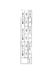
- FIG. 3 is a diagram for explaining an example of data of the arithmetic device according to the present embodiment.
- each column includes an input value in for each computing device 3, an output of the allocating unit 31 (analog value detection value in a and digital value detection value in g ), and the first safety function calculation unit 101.
- Each row is data for each of the arithmetic devices 3a to 3d.
- the same input value in is input to the arithmetic devices 3a to 3d.
- the allocating unit 31 of the arithmetic devices 3a to 3d distributes the input value in, outputs the detected value in g of the digital value to each first safety function calculating unit 101, and sets the detected value in a of the analog value respectively.
- the first safety function calculation units 101 of the calculation devices 3a to 3d output the logical calculation results 1 to 4 (out1), respectively.
- the second safety function calculation units 111 of the calculation devices 3a to 3d output analog calculation results 1 to 4 (out2), respectively.
- FIG. 4 is a diagram for explaining calculations performed by the first calculation unit 32 and the second calculation unit 33 according to the present embodiment.
- the first safety function calculation unit 101 of the first calculation unit 32 performs a logical operation on the detected value of the digital value.
- the second safety function verification unit 112 of the second calculation unit 33 performs a logical operation that is simulated by analog calculation on the detected value of the digital value.
- the second safety function calculation unit 111 of the second calculation unit 33 performs analog calculation (floating point calculation) on the detected value of the analog value.
- the first safety function verification unit 102 of the first calculation unit 32 performs integer calculation by emulation on the detected value of the analog value.
- FIG. 5 is a diagram for explaining an example of the outline of the calculation performed by the calculation device.
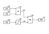
- digital value detection values DIN 1 151 and DIN 2 152 and an analog value detection value AIN 3 153 output from the input device 2 are input to the arithmetic device 3.
- reference numerals 161, 162, and 163 are calculation elements.
- Reference numeral 161 is an arithmetic element that performs a logical operation of logical sum
- reference numeral 163 is an arithmetic element that performs a logical operation of logical product.
- Reference numeral 162 denotes a calculation element that performs a calculation of a function that outputs an H level (also referred to as true or “1”) signal when the input value exceeds a predetermined value.
- the arithmetic device 3 stores arithmetic elements (addition, subtraction, division, limiter, broken line function, etc.) in advance as functions. Then, as shown in FIG. 5, the output of the calculation element 161 is connected to the input of the calculation element 163 with an arrow 181, and the output of the calculation element 162 is connected to the input of the calculation element 163 with an arrow 182. ing.
- the arithmetic device 3 executes a program converted from a configuration diagram (also referred to as a data flow) as shown in FIG. 5 into a program for performing a logical operation.
- the calculation element 161 when one of the detection values DIN 1 151 or DIN 2 152 of the digital value is at the H level (also referred to as true or “1”), the calculation element 161 outputs the H level to the calculation element 163. .
- the calculation element 162 When the analog value AIN 3 153 exceeds a predetermined value, the calculation element 162 outputs an H level to the calculation element 163. Then, the calculation element 163 obtains the calculation result DOUT 1 171 by taking a logical product of the output of the calculation element 161 and the output of the calculation element 162.
- FIG. 5 shows an outline for explaining the calculation performed by the calculation device 3.
- the calculation element 163 reduces the amount of heat when the detected value AIN 3 153 of the analog value exceeds a predetermined amount of heat.
- Information indicating an instruction to lower the amount of heat to the actuator 5 (for example, closing a valve for forcibly stopping fuel supply) is generated and output to the actuator 5 as a command value.
- the detection value DIN 1 151 or DIN 2 152 of the digital value is a detection value indicating the state of a switch for setting the amount of heat provided in the actuator 5
- the arithmetic device 3 may detect the detection value of the analog value described above.
- AIN 3 153 exceeds a predetermined amount of heat, information indicating an instruction to decrease the amount of heat is generated to the actuator 5 in order to decrease the amount of heat. And the arithmetic unit 3 outputs the state of the switch for setting the amount of heat to the actuator 5 as a command value.
- the detected digital value and the detected analog value input to the arithmetic device 3 are separately calculated.
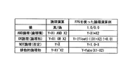
- FIG. 6 is a diagram for explaining an example of a calculation performed by the calculation device according to the present embodiment.
- each row is a correspondence relationship between an example of a logical operation using ALU and an example of a logical operation by a floating point operation using FPU
- each column shows an example of a logical operation using ALU and an FPU.
- It is an example of the logical operation by the used floating point arithmetic part.
- the values used in the logical operation are true and false.
- the values used in the logical operation by floating point arithmetic are 1.0 and 0.0.
- the operator “fabs” is an operator that takes an absolute value.
- FIG. 6 shows an example in which the logical operation is performed by a floating-point operation, but various other logical operations such as a negative logical product are realized by a floating-point operation by using other known floating-point operations. be able to.
- FIG. 7 is a flowchart of the processing procedure of the safety device according to the present embodiment.
- the detected value of the analog value and the detected value of the digital value output from the input device 2 are input to the arithmetic device 3 of the safety device 100.
- the distribution unit 31 of the arithmetic device 3 divides the detected analog value and the detected digital value output from the input device 2 into an detected analog value in a and a detected digital value in g (step S1). ).
- Sorting unit 31 outputs the detected value in g of the digital values, a first safety function computation unit 101 of the first arithmetic unit 32, and a second safety function computation verification unit 112 of the second operation unit 33.
- the distribution unit 31 outputs the detected analog value in a to the first safety function calculation verification unit 102 of the first calculation unit 32 and the second safety function calculation unit 111 of the second calculation unit 33.
- the first safety function computation unit 101 performs a logical operation on the detected values in g of the digital values sorting unit 31 outputs, to get an output value which is a control amount of the actuator 5, the operation result
- the out1 is output to the second safety function calculation verification unit 112 and the output control unit 35 (step 2). That is, the first safety function computation unit 101, a logical operation on the detected values in g of the digital values is performed in ALU.
- the second safety function computation verification unit 112 acquires the detection value in g of the digital values sorting unit 31 outputs, by performing a logical operation that simulates an analog operation, an output value which is a control amount of the actuator 5 (Step S3). That is, the second safety function calculation verification unit 112 executes a logical calculation simulated by an analog calculation with the FPU in order to verify the calculation result of the first safety function calculation unit 101.
- the second safety function calculation verification unit 112 determines whether or not the calculation result by the second safety function calculation verification unit 112 matches the calculation result out1 by the first safety function calculation unit 101 (step S4). As a result of the determination, when the calculation result by the second safety function calculation verification unit 112 matches the first safety function calculation unit 101 calculation result out1 (step S4: Yes), the second safety function calculation verification unit 112 Information indicating that the calculation result by the function calculation unit 101 is normal is output to the output control unit 35. The output control unit 35 outputs the calculation result output by the first safety function calculation unit 101 to the output device 4 based on the information indicating that the calculation result output by the second safety function calculation verification unit 112 is normal ( Step S5).
- step S4 when the calculation result by the second safety function calculation verification unit 112 does not match the calculation result out1 by the first safety function calculation unit 101 (step S4: No), the second safety function calculation verification unit 112 Is output to the output control unit 35.
- the output control unit 35 does not output the calculation result output by the first safety function calculation unit 101 to the output device 4 based on the information indicating that the calculation result output by the second safety function calculation verification unit 112 is abnormal ( Step S6).
- the second safety function calculation unit 111 performs an analog calculation on the detection value in a of the analog value output by the distribution unit 31 to obtain an output value that is a control amount of the actuator 5, and the calculation result out2 is output to the first safety function calculation verification unit 102 and the output control unit 35 (step S7).
- the second safety function calculation unit 111 performs analog calculation on the detected value in a of the analog value with the FPU.
- the first safety function calculation verifying unit 102 performs integer calculation by emulation on the detected analog value in a output from the allocating unit 31, and obtains an output value that is a control amount of the actuator 5 (step S8). ). That is, the first safety function calculation verification unit 102 emulates an integer calculation and executes it with the ALU in order to verify the calculation result of the second safety function calculation unit 111.
- the first safety function calculation verification unit 102 determines whether or not the calculation result by the first safety function calculation verification unit 102 matches the calculation result out2 by the second safety function calculation unit 111 (step S9). As a result of the determination, if the calculation result by the first safety function calculation verification unit 102 matches the calculation result out2 by the second safety function calculation unit 111 (step S9: Yes), the first safety function calculation verification unit 102 Is output to the output control unit 35.
- the output control unit 35 outputs the calculation result output by the second safety function calculation unit 111 to the output device 4 based on information indicating that the calculation result output by the first safety function calculation verification unit 102 is normal ( Step S10).
- step S9 when the calculation result by the first safety function calculation unit 102 does not match the calculation result out2 by the second safety function calculation verification unit 111 (step S9: No), the first safety function calculation verification unit 102 Is output to the output control unit 35.
- the output control unit 35 does not output the calculation result output by the second safety function calculation unit 111 to the output device 4 based on the information indicating that the calculation result output by the first safety function calculation verification unit 102 is abnormal ( Step S11).
- the calculation results calculated by the calculation devices 3a to 3d in steps S1 to S11 are input to the output device 4.
- the output device 4 performs majority processing on the input calculation result, and outputs a command value to the actuator 5 based on the majority processing (step S12).
- the output control unit 35 of the calculation device 3 outputs the calculation result output from the first safety function calculation unit 101 when the calculation result output from the second safety function calculation verification unit 112 is abnormal.
- the example which does not output to 4 was demonstrated.
- the output control unit 35 has information indicating that the calculation device 3 is abnormal because the calculation device 3 is abnormal. You may make it send.
- the output control unit 35 indicates that there is an abnormality in the calculation device 3, so that the output device 4 has an abnormality in the calculation device 3. You may make it send the information which shows.
- the output device 4 displays, for example, a unique number or the like of the arithmetic device 3 in which the abnormality has occurred on a display unit (not shown).
- the user of the safety device 100 may be notified.
- the calculation result is double-checked with different hardware (ALU and FPU) and different software (different calculation methods) in the calculation device 3, an effect that the abnormality of the calculation device 3 can also be detected.
- the different calculation methods include, for example, a logical operation on a digital value and a floating-point operation on an analog value, or a logical operation by a floating-point operation on a digital value and an integer operation by emulation on an analog value.
- the output device 4 When four calculation results are input from the calculation devices 3a to 3d, the output device 4 performs a majority decision based on the four calculation results. For example, if two or more of the four are output values that control the safe side, The output value for controlling the safe side is output to the actuator 5. Note that the output value for controlling the safe side is an output for controlling the controlled object in a safe state, and is set in advance.
- the output device 4 makes a majority decision with the three calculation results.
- the output value for controlling the safe side is output to the actuator 5.
- the output device 4 When two calculation results are input from the calculation devices 3a to 3d, that is, when the two calculation results are not output by the calculation device 3 due to an abnormality, the output device 4 outputs one of the two calculation results. If the above is the output value for controlling the safe side, the output value for controlling the safe side is output to the actuator 5. When one or more output values for controlling the safe side are not present, one of the input calculation results is output as a command value to the actuator 5 in accordance with a predetermined output order set in advance.
- the output device 4 When one calculation result is input from the calculation devices 3a to 3d, that is, when the three calculation results are not output by the calculation device 3 due to an abnormality, the output device 4 displays the input calculation result as a command value. Is output to the actuator 5 as follows. When no calculation result is input from the calculation devices 3a to 3d, that is, when four calculation results are not output by the calculation device due to an abnormality, the output device 4 is used for a preset safe operation. The control value is output to the actuator 5 as a command value.
- the majority process described above is performed by the output device 5 for each of a calculation value for an analog detection value and a calculation value for a detection value for a digital value.
- the first safety function calculation unit 101 and the second safety function calculation unit 111 may perform the calculations of step S2 and step S7 in parallel.
- steps S3, S4 and steps S8 to S9 may be performed in parallel by the first safety function calculation verification unit 102 and the second safety function calculation verification unit 112.
- FIG. 1 an example in which the arithmetic device 3 is multiplexed is shown.
- the hardware and software are different in one arithmetic device 3.
- the number of the arithmetic units 3 may be one without multiplexing.
- the safety device 100 of the present embodiment uses different hardware from the input value using the ALU (first arithmetic unit 32) and the FPU (second arithmetic unit 33) of one CPU (arithmetic unit 3).
- the calculation is performed using a calculation method different from that of wear.
- the safety device 100 of the present embodiment since the first calculation unit 32 performs a logical operation and the second calculation unit 33 performs a floating point calculation which is a different logical method, the software is various. Can have sex. As a result, the possibility of common mode failure can be reduced.
- the arithmetic unit 3 uses the ALU and FPU included in one CPU.
- the CPU includes a digital signal processor DSP
- the ALU and FPU are configured by the DSP. Also good. Or you may make it comprise ALU (1st calculating part 32) and FPU (2nd calculating part 33) by one digital signal processor DSP.
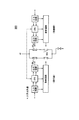
- FIG. 8 is a diagram illustrating an example of the configuration of the arithmetic device according to the second embodiment of the present invention.
- the arithmetic device 300 includes a first arithmetic unit 32a and a second arithmetic unit 33a.
- the arithmetic device 300 includes a distribution unit 31, a self-diagnosis unit 34, and an output control unit 35, as in FIG. 2 of the first embodiment.
- the second calculation unit 33a includes an input data unit 201, a calculation block (FB1) 202, a calculation block (FBj) 203, a calculation block (FBm) 204, and an output data unit 205.
- FB1 calculation block
- FBj calculation block
- FBm calculation block
- the first calculation unit 32 a includes an inverse calculation input data unit 211, an inverse calculation block (FB1 ⁇ 1 ) 212, a block (FBj ⁇ 1 ) 213, an inverse calculation block (FBm ⁇ 1 ) 214, and an inverse calculation output unit 215. ing.
- the distribution unit 31 of the arithmetic device 300 outputs the detected value of the analog value output from the input device 2 (FIG. 1) to the second arithmetic unit 33a.
- the calculation block (FB1) 202 to the calculation block (FBm) 204 sequentially calculate the input detection value of the analog value.
- the second calculation unit 33a uses the calculation result and the elements used during the calculation, as described later, from the inverse calculation block (FB1 ⁇ 1 ) 212 to the inverse calculation block (FBm ⁇ 1 ) 214 of the first calculation unit 32a. Output to.
- the first calculation unit 32a performs reverse calculation using the reverse calculation block (FB1 -1 ) 212 to reverse calculation block (FBm -1 ) 214 using the input calculation result and the elements used during the calculation. Validate the results.
- the first calculation unit 32a and the second calculation unit 33a are, for example, an ALU and an FPU included in one CPU (the calculation device 3).
- the input data unit 201 of the second calculation unit 33a outputs the detection value of the analog value output from the distribution unit 31 to the calculation block (FB1) 202. Further, the input data unit 201 stores a detection value of the input analog value.
- the calculation block (FB1) 202 to calculation block (FBm) 204 are configured to perform calculations necessary to generate the output of the safety function based on the detected analog value output from the allocating unit 31. Yes.
- Calculation block (FB1) 202, to the detected value of the analog values input data section 201 outputs, perform calculation using a predetermined function F 1.
- the calculation block (FB1) 202 outputs the calculation result (Y 1n ) to the calculation block (FBj) 203.
- the calculation block (FB1) 202 uses the input analog value detection value in (X 1n ), calculation result (Y 1n ), and elements (W 1n , V 1n ) used during the calculation as an inverse calculation block (FB 1 ). -1 ) Output to 212.
- the calculation block (FB1) 202 stores the element (W 1 (n ⁇ 1) ) used during the previous calculation. Note that the subscript n represents a value obtained by the current calculation, and n ⁇ 1 represents a value obtained by the previous calculation.
- the calculation block (FBj) 203 outputs the calculation result (Y jn ) to the calculation block (FBm) 204.
- the calculation block (FBj) 203 stores an element (W j (n ⁇ 1) ) used during the previous calculation.
- the calculation block (FBm) 204 stores an element (W m (n ⁇ 1) ) used during the previous calculation.
- the output data unit 205 determines that the computation of the computation block (FB1) 202 to the computation unit block (FBm) 204 has ended in response to the computation result output from the computation block (FBm) 204 being input. Further, the output data unit 205 outputs information indicating that the calculation is completed to the inverse calculation output unit 215.
- the inverse operation output unit 215 outputs information for starting the inverse operation to the inverse operation block (FBm ⁇ 1 ) 214 based on the information indicating that the operation output from the output data unit 205 has ended.
- the inverse operation block (FB1 ⁇ 1 ) 212 to the inverse operation block (FBm ⁇ 1 ) 214 are analog value detection values in (X 1n ) output from the operation block (FB 1) 202 to the operation block (FBm) 204, and the operation results.
- the inverse operation block (FBm ⁇ 1 ) 214 outputs information for starting the inverse operation to the inverse operation block (FBj ⁇ 1 ) 213.
- the inverse operation block (FBm ⁇ 1 ) 214 determines whether or not the inverse operation result X mn ′ matches the operation result X mn (also referred to as a mismatch check). As a result of the determination, when the inverse operation result X mn ′ matches the operation result X mn , the inverse operation block (FBm ⁇ 1 ) 214 determines that the operation result of the operation block (FBm) 204 is normal. As a result of the determination, if the inverse operation result X mn ′ and the operation result X jn do not match, the inverse operation block (FBm ⁇ 1 ) 214 determines that the operation result of the operation block (FBm) 204 is abnormal.
- the inverse operation block (FBm ⁇ 1 ) 214 outputs the determination result to the output control unit 35.
- the inverse operation block (FBm ⁇ 1 ) 214 indicates that the element W m (n ⁇ 1) ′ used in the middle of the inverse operation is the element W m ( It is determined whether or not it matches n ⁇ 1) .
- the reverse operation block ( FBm ⁇ 1 ) 214 determines that the calculation result of the calculation block (FBm) 204 is normal.
- the inverse operation block (FBm ⁇ 1 ) 214 overwrites and saves the element W mn used during the input operation over W m (n ⁇ 1) ′ so that it can be used in the inverse operation of the next cycle. To do. As a result of the determination, if the element W m (n ⁇ 1) ′ used during the reverse operation does not match the element W m (n ⁇ 1) used during the reverse operation, the reverse operation block (FBm ⁇ 1 ) 214 determines that the calculation result of the calculation block (FBm) 204 is abnormal. The inverse operation block (FBm ⁇ 1 ) 214 outputs the determination result to the output control unit 35.
- the inverse operation block (FBj ⁇ 1 ) 213 outputs information for starting the inverse operation to the inverse operation block (FB1 ⁇ 1 ) 212.
- the inverse operation block (FBj ⁇ 1 ) 213 determines whether or not the inverse operation result X jn ′ matches the operation result X jn . If the reverse operation result X jn ′ matches the operation result X jn as a result of the determination, the reverse operation block (FBj ⁇ 1 ) 213 determines that the operation result of the operation block (FBj) 203 is normal. As a result of the determination, if the inverse operation result X jn ′ and the operation result X jn do not match, the inverse operation block (FBj ⁇ 1 ) 213 determines that the operation result of the operation block (FBj) 203 is abnormal.
- the inverse operation block (FBj ⁇ 1 ) 213 outputs the determination result to the output control unit 35.
- the inverse operation block (FBj ⁇ 1 ) 213 includes an element W j (n ⁇ 1) ′ used in the middle of the reverse operation and an element W j (n ⁇ 1) used in the reverse operation of the previous cycle. It is determined whether or not it matches. As a result of the determination, if the element W j (n ⁇ 1) ′ used during the reverse operation matches the element W j (n ⁇ 1) used during the reverse operation of the previous cycle, the reverse operation block ( FBj ⁇ 1 ) 213 determines that the calculation result of the calculation block (FBj) 203 is normal.
- the inverse operation block (FBj ⁇ 1 ) 213 overwrites and saves the element W jn used during the input operation over W j (n ⁇ 1) ′ so that it can be used in the inverse operation of the next cycle. To do. As a result of the determination, if the element W j (n ⁇ 1) ′ used during the reverse operation does not match the element W j (n ⁇ 1) used during the reverse operation of the previous cycle, the reverse operation block ( FBj ⁇ 1 ) 213 determines that the calculation result of the calculation block (FBj) 203 is abnormal. The inverse operation block (FBj ⁇ 1 ) 213 outputs the determination result to the output control unit 35.
- the inverse operation block (FB1 ⁇ 1 ) 212 is based on the information for starting the inverse operation output from the inverse operation block (FBj ⁇ 1 ) 213, and the detected value in (X 1n ) of the analog value output from the operation block (FB 1) 201. ), Using the calculation result Y 1n and the elements (W 1 , V 1 ) used in the middle of the calculation, the inverse calculation is performed by a predetermined function F 1 ⁇ 1 .
- the inverse operation block (FB1 ⁇ 1 ) 212 outputs information indicating that the inverse operation is completed to the reverse edge calculation input data unit 211.
- the inverse operation block (FB1 ⁇ 1 ) 212 determines whether or not the inverse operation result X 1n ′ coincides with the detected value in (X 1n ) of the analog value. As a result of the determination, when the reverse operation result X 1n ′ matches the detected value in (X 1n ) of the analog value, the reverse operation block (FB1 ⁇ 1 ) 213 indicates that the operation result of the operation block (FB1) 202 is normal. Judge that there is. As a result of the determination, if the inverse operation result X 1n ′ does not match the detected value in (X 1n ) of the analog value, the inverse operation block (FB1 ⁇ 1 ) 212 has an abnormal operation result in the operation block (FB1) 202.
- the inverse operation block (FB1 ⁇ 1 ) 212 outputs the determination result to the output control unit 35. Further, the inverse operation block (FB1 ⁇ 1 ) 212 is configured such that the element W 1 (n ⁇ 1) ′ used during the reverse operation is the element W 1 (n ⁇ 1) used during the reverse operation of the previous cycle. It is determined whether or not it matches. As a result of the determination, if the element W 1 (n ⁇ 1) ′ used in the middle of the reverse operation matches the element W 1 (n ⁇ 1) used in the middle of the reverse operation of the previous cycle, the reverse operation block ( FB1 -1 ) 212 determines that the calculation result of the calculation block (FB1) 202 is normal.
- the inverse computation block (FB1 -1) 212 is an element W 1n used during the input operation to overwrite the W 1 (n-1) 'for use in the inverse of the next cycle storage To do. As a result of the determination, if the element W 1 (n ⁇ 1) ′ used during the reverse operation does not match the element W 1 (n ⁇ 1) used during the reverse operation of the previous cycle, the reverse operation block ( FB1 -1) 212 determines that the calculation block (FB1) 202 calculation result is abnormal. The inverse operation block (FB1 ⁇ 1 ) 212 outputs the determination result to the output control unit 35.
- the reverse calculation input data unit 211 outputs information indicating that the reverse calculation output from the calculation block (FB1) 212 has been completed to the output control unit 35.
- the output control unit 35 is information indicating that the reverse calculation output from the reverse calculation input data unit 211 is completed, and the determination result output from the reverse calculation block (FB1 ⁇ 1 ) 212 to the reverse calculation block (FBm ⁇ 1 ) 214.
- the calculation result of the calculation block (FBm) 204 is output as a command value to the output device 4.
- F 1 ⁇ 1 to F 3 ⁇ 1 are set in advance by the designer of the safety device 100 based on the input values.
- the inverse operation block (FB1 ⁇ 1 ) 212 to the inverse operation block (FBm ⁇ 1 ) 214 are reversed.
- the example which performs a calculation was demonstrated.
- the inverse operation block (FB1 ⁇ 1 ) 212 may perform the inverse operation after the operation of each operation block (FB1) 202 is completed.
- FIG. 9 is a diagram illustrating an example of input / output data of the calculation block and the inverse calculation block according to the present embodiment.
- FIG. 10 is a diagram for explaining an example of input / output data and retained data of the inverse operation block according to the present embodiment.
- the operation block (FB1) 202 ⁇ calculation block (FBm) 204 are X n each input, respectively Y n, and outputs the W n, and V n.
- the inverse computation block (FB1 -1) 212 ⁇ inverse computation block (FBm -1) 214 are respectively Y n, W n, V n , and X n are input, output X n ' To do.
- the inverse operation block (FB1 ⁇ 1 ) 212 to the inverse operation block (FBm ⁇ 1 ) 214 each hold W (n ⁇ 1) of the previous cycle.
- FIG. 11A is a diagram for explaining an example of a configuration of a calculation block according to the present embodiment.
- FIG. 11B is a diagram illustrating an example of the configuration of the inverse operation block according to the present embodiment.
- FIG. 12 is a diagram for explaining the processing procedure of the inverse operation block according to the present embodiment.
- FIG. 13 is a flowchart of the processing procedure of the inverse operation block according to the present embodiment.
- FIG. 11A and FIG. 11B show an example of the configuration of the 220 operation blocks (FBj) 203 and the inverse operation block (FBj ⁇ 1 ) 213 surrounded by the broken lines of the operation blocks in FIG.
- the operation block (FBj) 203 performs an operation using X jn and W j (n ⁇ 1) as input values and Y jn , W jn and V jn as output values.
- the inverse operation block (FBj ⁇ 1 ) 213 performs an inverse operation using Y jn , W jn and V jn as input values and X jn ′ and W j (n ⁇ 1) ′ as output values.
- the subscript n is data of the current cycle
- the subscript n-1 is data of the previous cycle.
- X jn is an input string
- Y jn is an output string.
- W jn is an intermediate data string (main operation value in the middle of calculating the output)
- V jn is intermediate data necessary to uniquely obtain X jn and W j (n ⁇ 1). is there.
- X jn ' is the inverse operation value X jn
- W j (n- 1)' is the inverse operation value W j (n-1)
- W j (n-1) is the last to Gyakuen Arabic This is a data string obtained by copying W jn of the cycle. As shown in FIG.
- the operation block (FBj) 203 applies a predetermined function F 2 to the input values X jn and W j (n ⁇ 1) , and outputs Y jn , W jn , V jn.
- the inverse operation block (FBj ⁇ 1 ) 213 applies a predetermined function F 2 ⁇ 1 to the input values Y jn , W jn, and V jn , and outputs the output value X jn ′ W j (N-1) 'is acquired.
- the reverse calculation procedure performed by the reverse calculation block (FBj ⁇ 1 ) 212 will be described in detail.
- the inverse operation block (FBj ⁇ 1 ) 212 copies the operation result Y jn of the operation block (FBj) 202 as an input value (step S101, C1, C2 in FIG. 12).
- the inverse operation block (FBj ⁇ 1 ) 212 copies the elements W jn and V jn used during the operation of the operation block (FBj) 202 as input values (step S102, C3 in FIG. 12).
- the inverse operation block (FBj ⁇ 1 ) 212 copies X jn that is an input value to the operation block (FBj) 202 as an output value (step S103, C4 in FIG.
- the inverse operation block (FBj ⁇ 1 ) 212 performs an inverse operation on the copied input values Y jn , W jn , and V jn using a predetermined function F 2 ⁇ 1 , and X jn ′ and W j j (n ⁇ 1) ′ is acquired (step S104, C5 in FIG. 13).
- the inverse operation block (FBj ⁇ 1 ) 212 determines whether or not X jn ′ obtained by the inverse operation matches the copied X jn (step S105). As a result of the determination, if X jn ′ obtained by the inverse operation matches the copied X jn (step S105: Yes), the process proceeds to step S107. As a result of the determination, if X jn ′ obtained by the inverse operation does not match the copied X jn (step S105: No), the process proceeds to step S106.
- the inverse operation block (FBj ⁇ 1 ) 212 determines whether or not the element W j (n ⁇ 1) ′ used during the inverse operation matches the copied W j (n ⁇ 1). (Step S107, C6 in FIG. 12). As a result of the determination, if W j (n ⁇ 1) ′ obtained by the inverse operation matches the copied W j (n ⁇ 1) (step S107: Yes), the process proceeds to step S108. As a result of the determination, if W j (n ⁇ 1) ′ obtained by the inverse operation does not match the copied W j (n ⁇ 1) (step S107: No), the process proceeds to step S106.
- the inverse operation block (FBj ⁇ 1 ) 212 determines that there is an abnormality because the calculation result or the elements used during the calculation do not match, and outputs the determination result to the output control unit 35 (step S106).
- the inverse calculation block (FBj ⁇ 1 ) 212 determines that the calculation result matches the element used during the calculation, and thus determines that the calculation result is normal, and outputs the determination result to the output control unit 35. Further, the inverse operation block (FBj ⁇ 1 ) 212 overwrites and saves the copied W jn over W j (n ⁇ 1) ′ so that it can be used in the inverse operation check in the next cycle (step S108, FIG. 12). C7).
- the first calculation unit 32a uses the calculation result acquired by the second calculation unit 33a and the elements used during the calculation. To perform the inverse operation. And the 1st calculating part 32a determines whether the calculation result which carried out reverse calculation corresponds with the input value of the calculation result which the 2nd calculating part 33a (FPU) acquired. Further, the first calculation unit 32a (ALU) also determines whether the element used during the reverse calculation matches the element used in the previous cycle. As a result, it is possible to check whether the calculation result is correct by using different hardware and different software, so that the possibility of common mode failure can be reduced at low cost.
- a calculation block (FB1) 202 to a calculation block (FBm) 204 and a reverse calculation block (FB1 ⁇ 1 ) 212 to a reverse calculation block (FBm ⁇ 1 ) 214 such as a calculation block (FB1) 202 to a calculation block (FBm) 204 and a reverse calculation block (FB1 ⁇ 1 ) 212 to a reverse calculation block (FBm ⁇ 1 ) 214.
- the number of operation blocks and inverse operation blocks is not limited to this, and may be determined based on detected values and command values to be detected.
- the configuration of the first embodiment may be added to the configuration of the present embodiment. In this case, the reliability can be further improved by the inverse calculation and the forward calculation performed by the first calculation unit 32a on the calculation result acquired by the second calculation unit 33a.
- an example in which only one arithmetic device 3 is used as shown in FIG. 8 has been described, but the arithmetic devices 3 may be multiplexed as in FIG.
- FIG. 14A is a diagram for explaining forward calculation of a digital value when there is one input according to the present embodiment.
- FIG. 14B is a diagram for explaining the inverse operation of a digital value when there is one input according to the present embodiment.
- one input if the output of one, the first calculation unit 32b, performs a predetermined function F to the input X n to obtain the output Y n.
- the second arithmetic unit 33b, X n by performing a function F -1 to the output Y n is compared with the X n 'inversely calculates, X n obtained by inversely calculating' Whether or not the calculation is normal can be determined.
- An example of such an operation is NOT logic (negative).
- FIG. 15A is a diagram for explaining forward calculation of digital values when there are two inputs according to the present embodiment.
- FIG. 15B is a diagram for explaining the inverse operation of the digital value when there are two inputs according to the present embodiment.
- the first calculation unit 32b performs a predetermined function F to the input X 1 and X 2 to obtain the output Yn.
- the second calculation unit 33 b uses the input X 2 and the output Y n as input values.
- a predetermined function F ⁇ 1 is applied to these X 2 and Y n to obtain X 1 ′. Then, it is possible to determine whether or not the calculation is normal by comparing X 1 ′ acquired by the second calculation unit 33b and the input X 1 . Examples of such operations include AND logic (logical product) and OR logic (logical sum).
- the calculation result obtained by the first calculation unit 32b (ALU) is opposite to the calculation result obtained by the second calculation unit 33b (FPU) by the first calculation unit 32b. Perform the operation. Then, the second calculation unit 33b (FPU) determines whether the calculated result of the reverse calculation matches the input value of the first calculation unit 32b (ALU). As a result, it is possible to check whether the calculation result is correct by using different hardware and different software, so that the possibility of common mode failure can be reduced at low cost.
- the configuration of the first embodiment may be added to the configuration of the present embodiment.
- the reliability can be further improved by performing the reverse calculation and the forward calculation on the calculation result obtained by the first calculation unit 32b.
- the configuration of the second embodiment may be added to the configuration of the present embodiment.
- the analog mode detection value and the digital value detection value are compared with different hardware and software, and the possibility of common mode failure can be reduced. .
- an example in which only one arithmetic device 3 is used as shown in FIG. 8 has been described, but the arithmetic devices 3 may be multiplexed as in FIG.
- one arithmetic device 3 includes an ALU and an FPU
- the arithmetic operation of the first arithmetic unit 32b is executed by the ALU
- the arithmetic operation of the second arithmetic unit 33b is executed by the FPU.
- the FPU can be operated in parallel with the ALU by the superscaler, so that this embodiment can be realized.
- a dual core processor including a plurality of calculation units in one CPU, for example, is used for the calculation device 3, the same effect as in the present embodiment can be obtained.
- the present invention can be applied to plants such as a thermal power plant, a hydraulic power plant, and a power plant.
Landscapes
- Engineering & Computer Science (AREA)
- Physics & Mathematics (AREA)
- General Physics & Mathematics (AREA)
- Automation & Control Theory (AREA)
- General Engineering & Computer Science (AREA)
- Theoretical Computer Science (AREA)
- Quality & Reliability (AREA)
- Safety Devices In Control Systems (AREA)
- Programmable Controllers (AREA)
Abstract
Description
本願は、2011年1月31日に、日本に出願された特願2011-018220号に基づき優先権を主張し、その内容をここに援用する。
図1は、本発明の第1実施形態に係る安全装置の構成図である。なお、本実施形態の安全装置は、火力プラント、水力プラント、電力プラントなどのプラントに適用する例を説明するが、工場の生産ライン、ビルのメンテナンスシステム、大型空調システムなどの分散型制御による安全装置が用いられているシステムにも適用してもよい。
アクチュエータ5は、例えば、発電用のガスタービンの燃料供給を強制停止する弁である。また、安全装置100には、センサ1が取り付けられている。アクチュエータ5は、安全装置100が出力する指令値に基づき動作する。
センサ1は、熱量や流量などのアナログ値を検出する。また、センサ1は、アクチュエータ5に取り付けられている不図示の各種スイッチの論理状態などのデジタル値を検出する。センサ1は、アナログ値の検出値と、デジタル値の検出値とを、安全装置100に出力する。
演算装置3aは、入力装置2が出力するアナログ値の検出値とデジタル値の検出値とに対し、それぞれ演算処理を施し、演算結果を出力装置4に出力する。
演算装置3bは、入力装置2が出力するアナログ値の検出値とデジタル値の検出値とに対し、それぞれ演算処理を施し、演算結果を出力装置4に出力する。
演算装置3cは、入力装置2が出力するアナログ値の検出値とデジタル値の検出値とに対し、それぞれ演算処理を施し、演算結果を出力装置4に出力する。
演算装置3dは、入力装置2が出力するアナログ値の検出値とデジタル値の検出値とに対し、それぞれ演算処理を施し、演算結果を出力装置4に出力する。
出力装置4は、演算装置3a~3dが出力する演算結果に対して、後述するように多数決処理を行い、多数決結果に基づき選ばれた演算結果を指令値としてアクチュエータ5に出力する。
以下、演算装置3a~3dを総称して「演算装置3」と称する。
第1安全機能演算部101は、振分部31が出力するデジタル値の検出値ingに対して論理演算(第1の演算)を行い、アクチュエータ5の制御量である出力値を取得し、演算結果out1を第2安全機能演算検証部112と出力制御部35とに出力する。
第1安全機能演算検証部102は、振分部31が出力するアナログ値の検出値inaに対して、エミュレーションによる公知の整数演算(第2の演算)を行い、アクチュエータ5の制御量である出力値を取得する。第1安全機能演算検証部102は、この演算結果が、第2安全機能演算部111による演算結果out2と一致するか否かを判定する。第1安全機能演算検証部102は、判定の結果、第1安全機能演算検証部102による演算結果が、第2安全機能演算部111による演算結果out2と一致する場合、演算結果が正常であることを示す情報を出力制御部35に出力する。第1安全機能演算検証部102は、判定の結果、第1安全機能演算検証部102による演算結果が、第2安全機能演算部111による演算結果out2と一致しない場合、演算結果が異常であることを示す情報を出力制御部35に出力する。
第2安全機能演算部111は、振分部31が出力するアナログ値の検出値inaに対して浮動小数点演算(第1の演算)を行って、アクチュエータ5の制御量である出力値を取得し、演算結果out2を第1安全機能演算検証部102と出力制御部35とに出力する。
第2安全機能演算検証部112は、振分部31が出力するデジタル値の検出値ingに対して、後述するようにアナログ演算で模擬した論理演算(第2の演算)を行って、アクチュエータ5の制御量である出力値を取得する。第2安全機能演算検証部112は、この演算結果が、第1安全機能演算部101による演算結果out1と一致するか否かを判定する。第2安全機能演算検証部112は、判定の結果、第2安全機能演算検証部112による演算結果が、第1安全機能演算部101による演算結果out1と一致する場合、演算結果が正常であることを示す情報を出力制御部35に出力する。第2安全機能演算検証部112は、判定の結果、第1安全機能演算検証部112による演算結果が、第1安全機能演算部101による演算結果out1と一致しない場合、演算結果が異常であることを示す情報を出力制御部35に出力する。
出力制御部35は、第1安全機能演算検証部102が出力する情報が、演算結果が正常であることを示す情報である場合、第2安全機能演算部111が出力するアナログ値の演算結果を出力装置4に出力する。出力制御部35は、第2安全機能演算検証部112が出力する情報が、演算結果が正常であることを示す情報である場合、第1安全機能演算部101が出力するデジタル値の演算結果を出力装置4に出力する。
出力制御部35は、第1安全機能演算検証部102が出力する情報が、演算結果が異常であることを示す情報である場合、第2安全機能演算部111が出力するアナログ値の演算結果を出力装置4に出力しない。出力制御部35は、第2安全機能演算検証部112が出力する情報が、演算結果が異常であることを示す情報である場合、第1安全機能演算部101が出力するデジタル値の演算結果を出力装置4に出力しない。
また、第2演算部33の第2安全機能演算部111は、アナログ値の検出値に対してアナログ演算(浮動小数点演算)を行う。この演算結果を検証するために、第1演算部32の第1安全機能検証部102は、アナログ値の検出値に対してエミュレーションによる整数演算を行う。
図5に示すように、演算装置3には、入力装置2が出力するデジタル値の検出値DIN1151、およびDIN2152、アナログ値の検出値AIN3153が入力されている。図5において、符号161、162、および163が演算要素である。符号161は、論理和の論理演算を行う演算要素であり、符号163は、論理積の論理演算を行う演算要素である。また、符号162は、入力値が所定の値を超えたときにHレベル(真または“1”ともいう)の信号を出力する関数の演算を行う演算要素である。このように、演算装置3は、予め演算要素(加算、減算、除算、リミッタ、折れ線関数など)を関数化して記憶している。そして、図5に示すように、演算要素161の出力を演算要素163の入力に矢印181で接続し、演算要素162の出力を演算要素163の入力に矢印182で接続して、ロジックを構成している。演算装置3は、図5に示したような構成図(データフローともいう)から、論理演算を行うプログラムに変換したものを実行する。
また、図5に示したのは、演算装置3が行う演算を説明するための概略である。実際の演算は、例えば、アナログ値の検出値AIN3153が熱量の場合、演算要素163は、このアナログ値の検出値AIN3153が所定の熱量を超えた場合に、熱量を下げるために、アクチュエータ5に熱量を下げる指示を示す情報(例えば、燃料供給を強制停止する弁を閉じる)を生成して、アクチュエータ5に指令値として出力する。
また、例えば、デジタル値の検出値DIN1151かDIN2152が、アクチュエータ5が備える熱量を設定するためのスイッチの状態を示す検出値の場合、演算装置3は、上記のアナログ値の検出値AIN3153が所定の熱量を超えた場合に、熱量を下げるために、アクチュエータ5に熱量を下げる指示を示す情報を生成する。そして、演算装置3は、アクチュエータ5に熱量を設定するためのスイッチの状態を指令値として出力する。
以下の説明では、演算装置3の動作の説明を簡略化するために、演算装置3に入力されたデジタル値の検出値、アナログ値の検出値を、各々、別々に演算する例を説明する。
図6において、各行はALUを使った論理演算の例とFPUを使った浮動小数点演算による論理演算の例との対応関係であり、各列は、ALUを使った論理演算の例と、FPUを使った浮動小数点演算部による論理演算の例である。図6に示すように、論理演算で用いる値は、真と偽である。また、浮動小数点演算による論理演算で用いる値は、1.0と0.0である。
論理積Y=(X1)AND(X2)は、浮動小数点演算で行う場合、Y=(X1)×(X2)の演算を行う。
論理和Y=(X1)OR(X2)は、浮動小数点演算で行う場合、Y=float((X1)+(X2))!=0.0)の演算を行う。なお、演算子「float」は、4バイト浮動小数点であり、演算子「!=」は、比較演算子で異なる場合である。すなわち、X1とX2の和が0.0と異なる場合、Y=1.0であり、X1とX2の和が0の場合、Y=0.0である。
否定Y=X~は、浮動小数点演算で行う場合、Y=1.0-Xの演算を行う。
排他的論理和Y=(X1)^(X2)は、浮動小数点演算で行う場合、Y=fabs(X1-X2)の演算を行う。演算子「fabs」は、絶対値を取る演算子である。すなわち、X1とX2との差の絶対値を演算する。
なお、図6には、論理演算を浮動小数点演算で行う一例を示したが、他にも公知の浮動小数点演算を用いることで、否定論理積等の各種の論理演算を浮動小数点演算で実現することができる。
まず、安全装置100の演算装置3には、入力装置2が出力するアナログ値の検出値とデジタル値の検出値とが入力される。
演算装置3の振分部31は、入力装置2が出力するアナログ値の検出値とデジタル値の検出値を、アナログ値の検出値inaとデジタル値の検出値ingとに分ける(ステップS1)。
振分部31は、デジタル値の検出値ingを、第1演算部32の第1安全機能演算部101と、第2演算部33の第2安全機能演算検証部112とに出力する。振分部31は、アナログ値の検出値inaを、第1演算部32の第1安全機能演算検証部102と、第2演算部33の第2安全機能演算部111とに出力する。
第2安全機能演算検証部112は、振分部31が出力するデジタル値の検出値ingに対して、アナログ演算で模擬した論理演算を行って、アクチュエータ5の制御量である出力値を取得する(ステップS3)。すなわち、第2安全機能演算検証部112は、第1安全機能演算部101の演算結果を検証するために、アナログ演算で模擬した論理演算を、FPUで実行する。
判定の結果、第2安全機能演算検証部112による演算結果が第1安全機能演算部101演算結果out1と一致する場合(ステップS4:Yes)、第2安全機能演算検証部112は、第1安全機能演算部101による演算結果が正常であることを示す情報を出力制御部35に出力する。
出力制御部35は、第2安全機能演算検証部112が出力する演算結果が正常であることを示す情報に基づき、第1安全機能演算部101が出力する演算結果を出力装置4に出力する(ステップS5)。
判定の結果、第2安全機能演算検証部112による演算結果が第1安全機能演算部101による演算結果out1と一致しない場合(ステップS4:No)、第2安全機能演算検証部112は、演算結果が異常であることを示す情報を出力制御部35に出力する。
出力制御部35は、第2安全機能演算検証部112が出力する演算結果が異常であることを示す情報に基づき、第1安全機能演算部101が出力する演算結果を出力装置4に出力しない(ステップS6)。
第1安全機能演算検証部102は、振分部31が出力するアナログ値の検出値inaに対して、エミュレーションにより整数演算を行い、アクチュエータ5の制御量である出力値を取得する(ステップS8)。すなわち、第1安全機能演算検証部102は、第2安全機能演算部111の演算結果を検証するために、整数演算をエミュレートして、ALUで実行する。
判定の結果、第1安全機能演算検証部102による演算結果が第2安全機能演算部111による演算結果out2と一致する場合(ステップS9:Yes)、第1安全機能演算検証部102は、演算結果が正常であることを示す情報を出力制御部35に出力する。
出力制御部35は、第1安全機能演算検証部102が出力する演算結果が正常であることを示す情報に基づき、第2安全機能演算部111が出力する演算結果を出力装置4に出力する(ステップS10)。
判定の結果、第1安全機能演算部102による演算結果が第2安全機能演算検証部111による演算結果out2と一致しない場合(ステップS9:No)、第1安全機能演算検証部102は、演算結果が異常であることを示す情報を出力制御部35に出力する。
出力制御部35は、第1安全機能演算検証部102が出力する演算結果が異常であることを示す情報に基づき、第2安全機能演算部111が出力する演算結果を出力装置4に出力しない(ステップS11)。
出力装置4は、演算装置3が出力する異常があることを示す情報が入力された場合、例えば、不図示の表示部に異常が発生している演算装置3の固有の番号等を表示して、安全装置100の使用者に知らせるようにしてもよい。この場合、演算装置3内で、異なるハードウェア(ALUとFPU)と異なるソフトウェア(異なる演算方式)で2重に演算結果を確認しているため、演算装置3の異常を検出することもできる効果がある。
なお、異なる演算方式とは、例えばデジタル値に対する論理演算とアナログ値に対する浮動少数点演算であり、または、デジタル値に対する浮動小数点演算による論理演算とアナログ値に対するエミュレーションによる整数演算などである。
演算装置3a~3dから、4つの演算結果が入力された場合、出力装置4は、4つの演算結果で多数決を行い、例えば、4つのうち2つ以上が安全側を制御する出力値であれば、安全側を制御する出力値をアクチュエータ5に出力する。なお、安全側を制御する出力値とは、制御対象を安全な状態に制御する出力で、予め設定しておく。
演算装置3a~3dから、3つの演算結果が入力された場合、すなわち、1つの演算結果が異常のため演算装置3により出力されなかった場合、出力装置4は、3つの演算結果で多数決を行い、例えば、3つのうち2つ以上が安全側を制御する出力値であれば、安全側を制御する出力値をアクチュエータ5に出力する。
演算装置3a~3dから、2つの演算結果が入力された場合、すなわち、2つの演算結果が異常のため演算装置3により出力されなかった場合、出力装置4は、2つの演算結果のうち1つ以上が安全側を制御する出力値であれば、安全側を制御する出力値をアクチュエータ5に出力する。安全側を制御する出力値が1つ以上なかった場合、予め設定してある所定の出力順序に従って、入力された演算結果のうちの一方の演算結果を指令値としてアクチュエータ5に出力する。
演算装置3a~3dから、1つの演算結果が入力された場合、すなわち、3つの演算結果が異常のため演算装置3により出力されなかった場合、出力装置4は、入力された演算結果を指令値としてアクチュエータ5に出力する。
演算装置3a~3dから、1つも演算結果が入力されない場合、すなわち、4つの演算結果が異常のため演算装置により出力されなかった場合、出力装置4は、予め設定されている安全動作のための制御値を指令値としてアクチュエータ5に出力する。
また、図7に示したフローチャートにおいて、例えば、ステップS2とステップS7の演算を、第1安全機能演算部101と第2安全機能演算部111が並行して行うようにしてもよい。また、ステップS3、S4とステップS8~S9を、第1安全機能演算検証部102と第2安全機能演算検証部112が並行して行うようにしてもよい。
また、図1の構成例では、演算装置3を多重する例を示したが、本実施形態の安全装置100を用いる場合、1つの演算装置3内で異なるハードウェアとソフトウェアで確認しているため、多重化せずに演算装置3は1つでもよい。
図8は、本発明の第2実施形態に係る演算装置の構成の一例を説明する図である。図8に示すように、本実施形態に係る演算装置300は、第1演算部32a、第2演算部33aを備えている。また、図8には示していないが、第1実施形態の図2と同様に、演算装置300は、振分部31、自己診断部34、出力制御部35を備えている。また、第2演算部33aは、入力データ部201、演算ブロック(FB1)202、演算ブロック(FBj)203、演算ブロック(FBm)204、出力データ部205を備えている。第1演算部32aは、逆演算用入力データ部211、逆演算ブロック(FB1-1)212、ブロック(FBj-1)213、逆演算ブロック(FBm-1)214、逆演算出力部215を備えている。
演算装置300の振分部31は、入力装置2(図1)が出力するアナログ値の検出値を第2演算部33aに出力する。第2演算部33aでは、入力されたアナログ値の検出値に対して、順次、演算ブロック(FB1)202~演算ブロック(FBm)204が演算を行う。また、第2演算部33aは、演算結果と演算の途中で使用した要素を、後述するように第1演算部32aの逆演算ブロック(FB1-1)212~逆演算ブロック(FBm-1)214に出力する。
第1演算部32aは、入力された演算結果と演算の途中で使用した要素を用いて、逆演算ブロック(FB1-1)212~逆演算ブロック(FBm-1)214により逆演算を行い、演算結果を検証する。また、第1実施形態と同様に、第1演算部32aと第2演算部33aは、例えば、1つのCPU(演算装置3)が備えるALUとFPUである。
演算ブロック(FB1)202~演算ブロック(FBm)204は、振分部31が出力するアナログ値の検出値に基づいて、安全機能の出力を生成するのに必要な演算を行うために構成されている。
演算ブロック(FB1)202は、入力データ部201が出力するアナログ値の検出値に対して、所定の関数F1により演算を行う。演算ブロック(FB1)202は、演算結果(Y1n)、を演算ブロック(FBj)203に出力する。さらに演算ブロック(FB1)202は、入力されたアナログ値の検出値in(X1n)、演算結果(Y1n)、演算の途中で使用した要素(W1n、V1n)を逆演算ブロック(FB1-1)212に出力する。また、演算ブロック(FB1)202は、前回の演算の途中で使用した要素(W1(n-1))を記憶している。なお、添え字nは、今回の演算による値を表し、n-1は前回の演算による値表している。
逆演算ブロック(FB1-1)212~逆演算ブロック(FBm-1)214は、演算ブロック(FB1)202~演算ブロック(FBm)204が出力するアナログ値の検出値in(X1n)、演算結果(Y1n(=Xjn))、(Yjn(=Xmn))、および(Ymn)、演算の途中で用いた要素(W1n、V1n)、(Wjn、Vjn)および(Wmn、Vmn)に基づいて、逆演算を行うために構成されている。
また、逆演算ブロック(FBm-1)214は、逆演算結果Xmn’が演算結果Xmnと一致するか否かを判定する(不一致チェックともいう)。判定の結果、逆演算結果Xmn’と演算結果Xmnとが一致した場合、逆演算ブロック(FBm-1)214は、演算ブロック(FBm)204の演算結果が正常であると判定する。判定の結果、逆演算結果Xmn’と演算結果Xjnとが一致しない場合、逆演算ブロック(FBm-1)214は、演算ブロック(FBm)204の演算結果が異常であると判定する。逆演算ブロック(FBm-1)214は、判定結果を、出力制御部35に出力する。
また、逆演算ブロック(FBm-1)214は、逆演算の途中で使用した要素Wm(n-1)’が、記憶されている前回の周期の逆演算の途中で使用した要素Wm(n-1)と一致するか否かを判定する。判定の結果、逆演算の途中で使用した要素Wm(n-1)’と前回の周期の逆演算の途中で使用した要素Wm(n-1)とが一致した場合、逆演算ブロック(FBm-1)214は、演算ブロック(FBm)204の演算結果が正常であると判定する。また、逆演算ブロック(FBm-1)214は、入力された演算の途中で使用した要素Wmnを次回の周期の逆演算で使用できるようにWm(n-1)’に上書きして保存する。
判定の結果、逆演算の途中で使用した要素Wm(n-1)’と逆演算の途中で使用した要素Wm(n-1)とが一致しない場合、逆演算ブロック(FBm-1)214は、演算ブロック(FBm)204の演算結果が異常であると判定する。逆演算ブロック(FBm-1)214は、判定結果を、出力制御部35に出力する。
また、逆演算ブロック(FBj-1)213は、逆演算結果Xjn’が、演算結果Xjnと一致するか否かを判定する。判定の結果、逆演算結果Xjn’と演算結果Xjnとが一致した場合、逆演算ブロック(FBj-1)213は、演算ブロック(FBj)203の演算結果が正常であると判定する。判定の結果、逆演算結果Xjn’と演算結果Xjnとが一致しない場合、逆演算ブロック(FBj-1)213は、演算ブロック(FBj)203の演算結果が異常であると判定する。逆演算ブロック(FBj-1)213は、判定結果を、出力制御部35に出力する。
また、逆演算ブロック(FBj-1)213は、逆演算の途中で使用した要素Wj(n-1)’が、前回の周期の逆演算の途中で使用した要素Wj(n-1)と一致するか否かを判定する。判定の結果、逆演算の途中で使用した要素Wj(n-1)’と前回の周期の逆演算の途中で使用した要素Wj(n-1)とが一致した場合、逆演算ブロック(FBj-1)213は、演算ブロック(FBj)203の演算結果が正常であると判定する。また、逆演算ブロック(FBj-1)213は、入力された演算の途中で使用した要素Wjnを次回の周期の逆演算で使用できるようにWj(n-1)’に上書きして保存する。
判定の結果、逆演算の途中で使用した要素Wj(n-1)’と前回の周期の逆演算の途中で使用した要素Wj(n-1)とが一致しない場合、逆演算ブロック(FBj-1)213は、演算ブロック(FBj)203の演算結果が異常であると判定する。逆演算ブロック(FBj-1)213は、判定結果を、出力制御部35に出力する。
また、逆演算ブロック(FB1-1)212は、逆演算結果X1n’が、アナログ値の検出値in(X1n)と一致するか否かを判定する。判定の結果、逆演算結果X1n’とアナログ値の検出値in(X1n)とが一致した場合、逆演算ブロック(FB1-1)213は、演算ブロック(FB1)202の演算結果が正常であると判定する。判定の結果、逆演算結果X1n’とアナログ値の検出値in(X1n)とが一致しない場合、逆演算ブロック(FB1-1)212は、演算ブロック(FB1)202の演算結果が異常であると判定する。逆演算ブロック(FB1-1)212は、判定結果を、出力制御部35に出力する。
また、逆演算ブロック(FB1-1)212は、逆演算の途中で使用した要素W1(n-1)’が、前回の周期の逆演算の途中で使用した要素W1(n-1)と一致するか否かを判定する。判定の結果、逆演算の途中で使用した要素W1(n-1)’と前回の周期の逆演算の途中で使用した要素W1(n-1)とが一致した場合、逆演算ブロック(FB1-1)212は、演算ブロック(FB1)202の演算結果が正常であると判定する。また、逆演算ブロック(FB1-1)212は、入力された演算の途中で使用した要素W1nを次回の周期の逆演算で使用できるようにW1(n-1)’に上書きして保存する。
判定の結果、逆演算の途中で使用した要素W1(n-1)’と前回の周期の逆演算の途中で使用した要素W1(n-1)とが一致しない場合、逆演算ブロック(FB1-1)212は、演算ブロック(FB1)202の演算結果が異常であると判定する。逆演算ブロック(FB1-1)212は、判定結果を、出力制御部35に出力する。
出力制御部35は、逆演算用入力データ部211が出力する逆演算が終了したことを示す情報、逆演算ブロック(FB1-1)212~逆演算ブロック(FBm-1)214が出力する判定結果に基づき、演算ブロック(FB1)202~演算ブロック(FBm)204の演算が正常である場合、演算ブロック(FBm)204の演算結果を指令値として出力装置4に出力する。
図9に示すように、演算ブロック(FB1)202~演算ブロック(FBm)204は、それぞれXnが入力され、それぞれYn、Wn、およびVnを出力する。
図10に示すように、逆演算ブロック(FB1-1)212~逆演算ブロック(FBm-1)214は、それぞれYn、Wn、Vn、およびXnが入力され、Xn’を出力する。また、逆演算ブロック(FB1-1)212~逆演算ブロック(FBm-1)214は、それぞれ前回の周期のW(n-1)を保持している。
図11Aに示すように、演算ブロック(FBj)203は、Xjn、Wj(n-1)を入力値、Yjn、WjnおよびVjnを出力値とする演算を行う。図11Bに示すように、逆演算ブロック(FBj-1)213は、Yjn、WjnおよびVjnを入力値、Xjn’、Wj(n-1)’を出力値とする逆演算を行う。
図11Aと図11Bにおいて、添え字nは、今回の周期のデータ、添え字n-1は、前回の周期のデータである。また、Xjnは、入力列、Yjnは、出力列である。さらに、Wjnは、中間データ列(出力を計算するまでの途中の主要な演算値)、Vjnは、Xjnと Wj(n-1)を一意的に求めるために必要な中間データである。Xjn’は、Xjnの逆演算値、Wj(n-1)’は、Wj(n-1)の逆演算値であり、Wj(n-1)は、逆縁算用に前回の周期のWjnをコピーしたデータ列である。
図11Aに示すように、演算ブロック(FBj)203は、入力値のXjnとWj(n-1)に対して所定の関数F2施して、出力値のYjn、Wjn、Vjnを取得する。
図11Bに示すように、逆演算ブロック(FBj-1)213は、入力値のYjnとWjnおよびVjnに対して所定の関数F2 -1を施して、出力値Xjn’Wj(n-1)’を取得する。
まず、逆演算ブロック(FBj-1)212は、演算ブロック(FBj)202の演算結果Yjnを入力値としてコピーする(ステップS101、図12のC1、C2)。
次に、逆演算ブロック(FBj-1)212は、演算ブロック(FBj)202の演算の途中で使用した要素WjnとVjnを、入力値としてコピーする(ステップS102、図12のC3)。
次に、逆演算ブロック(FBj-1)212は、演算ブロック(FBj)202への入力値であるXjnを、出力値としてコピーする(ステップS103、図12のC4)。
次に、逆演算ブロック(FBj-1)212は、コピーした入力値Yjn、Wjn、およびVjnに対して、所定の関数F2 -1により逆演算を行って、Xjn’とWj(n-1)’を取得する(ステップS104、図13のC5)。
判定の結果、逆演算により求めたXjn’と、コピーしたXjnとが一致する場合(ステップS105:Yes)、ステップS107に進む。判定の結果、逆演算により求めたXjn’と、コピーしたXjnとが一致しない場合(ステップS105:No)、ステップS106に進む。
判定の結果、逆演算により求めたWj(n-1)’と、コピーしたWj(n-1)とが一致する場合(ステップS107:Yes)、ステップS108に進む。判定の結果、逆演算により求めたWj(n-1)’と、コピーしたWj(n-1)とが一致しない場合(ステップS107:No)、ステップS106に進む。
また、本実施形態の構成に実施形態1の構成を加えるようにしてもよい。この場合、第2演算部33aが取得した演算結果に対し、第1演算部32aが逆演算と、順方向の演算を行うこととで、さらに信頼性を上げることができる。
また、本実施形態では、図8のように1つの演算装置3についてのみ用いる例を説明したが、図1と同様に、演算装置3を多重化してもよい。
第2実施形態では、アナログ値の検出値が演算装置3に入力された場合、第2演算部33aが演算した演算結果に対して、第1演算部32aが逆演算して判定する例を説明した。本実施形態では、デジタル値の検出値が演算装置3に入力された場合、第1演算部32bが演算した演算結果に対して、第2演算部33bが逆演算して判定する例を説明する。なお、第2演算部33bは、第1実施形態で説明したように、デジタル値を浮動小数点演算により論理演算することで行う。
図14Aに示すように、入力が1個、出力が1個の場合、第1演算部32bは、入力Xnに対して所定の関数Fを施して出力Ynを取得する。また、図14Bに示すように、第2演算部33bは、出力Ynに関数F-1を施してXn’を逆演算し、逆演算したXn’とXnとを比較することで、演算が正常か否かを判定できる。このような演算として、例えば、NOT論理(否定)がある。
図15Aに示すように、入力が2個、出力が1個の場合、第1演算部32bは、入力X1とX2に対して所定の関数Fを施して出力Ynを取得する。ここで、出力Ynのみでは、入力X1、X2を一意に求めることができないため、例えば、図15Bに示すように、第2演算部33bが、入力X2と出力Ynを入力値とし、これらX2とYnに対して所定の関数F-1を施して、X1’を取得する。そして、第2演算部33bが取得したX1’と入力のX1とを比較することで演算が正常か否かを判定できる。このような演算として、例えば、AND論理(論理積)、OR論理(論理和)などがある。
また、本実施形態の構成に実施形態2の構成を加えるようにしてもよい。この場合、アナログ値の検出値に対してもデジタル値の検出値に対しても、異なるハードウェア、ソフトウェアで逆演算して比較しているため、コモンモード故障の可能性を低くすることができる。
また、本実施形態では、図8のように1つの演算装置3についてのみ用いる例を説明したが、図1と同様に、演算装置3を多重化してもよい。
2 入力装置
3、3a~3d、300 演算装置
4 出力装置
31 振分部
32、32a、32b 第1演算部
33、33a、33b 第2演算部
34 自己診断部
35 出力制御部
101 第1安全機能演算部
102 第1安全機能演算検証部
111 第2安全機能演算部
112 第2安全機能演算検証部
201 入力データ部
202~204 演算ブロックFB1~演算部ブロックFBm
212~214 逆演算ブロックFB1-1~逆演算ブロックFBm-1
205 出力データ部
211 逆演算用入力データ部
215 逆演算出力部
Claims (11)
- 制御対象から検出された検出値に対して第1演算を行って第1結果値を取得する第1演算部と、
前記検出値に対して第2演算を行って第2結果値を取得し、前記第1結果値と、前記第2結果値とが一致するか否かを判定する第2演算部と、
前記第2演算部が前記第1結果値と前記第2結果値とが一致すると判定した場合、前記第1結果値を出力し、前記第2演算部が前記第1結果値と前記第2結果値とが一致しないと判定した場合、前記第1結果値を出力しない出力制御部と、
前記第1演算部および前記第2演算部を備える第1中央演算処理装置と、
を備え、
前記第1演算部と前記第2演算部とが異なるハードウェアである安全装置。 - 前記第1演算が論理演算であり且つ前記第2演算が浮動小数点演算であるか、または、前記第2演算が論理演算であり且つ前記第1演算が浮動小数点演算である請求項1に記載の安全装置。
- 前記第1演算が前記論理演算であり且つ前記第2演算が前記浮動小数点演算である場合、前記第1演算部が前記論理演算を行い且つ前記第2演算部が前記論理演算を浮動小数点演算により模擬して行い、
前記第2演算が前記論理演算であり且つ前記第1演算が前記浮動小数点演算である場合、前記第1演算部が前記浮動小数点演算を行い且つ第2演算部がエミュレーションにより整数演算を行う請求項2に記載の安全装置。 - 前記第1演算部は、
前記第1演算の途中で第3結果値を取得し、前記検出値と、前記第1結果値と、前記第3結果値とを、前記第2演算部に入力し、
前記第2演算部は、
前記第1結果値及び前記第3結果値を用いて、前記第1演算の逆演算を行って第4結果値を取得し、当該第4結果値と検出値とが一致するか否かを判定し、
出力制御部は、
前記第2演算部が前記検出値と前記第4結果値とが一致すると判定した場合、前記第1結果値を出力し、前記第2演算部が前記検出値と前記第4演算結果とが一致しないと判定した場合、前記第1結果値を出力しない請求項1に記載の安全装置。 - 前記第1中央演算処理装置と同一構造を有し、前記第1中央演算処理装置と並列に接続された第2中央演算処理装置と、
前記第1中央演算処理装置の前記出力制御部が出力する前記第1結果値と、前記第2中央演算処理装置の前記出力制御部が出力する第5結果値とに基づいて、前記制御対象を制御するための指令値を決定する出力装置をさらに備える請求項1に記載の安全装置。 - 前記出力制御部は、
前記第2演算部が前記第1結果値と前記第2結果値とが一致しないと判定した場合、前記第1演算部または前記第2演算部に異常があることを示す情報を前記出力装置に出力し、
前記出力装置は、
前記情報に基づき、前記指令値を決定する請求項5に記載の安全装置。 - 制御対象から検出された検出値に対して第1演算を行って第1結果値を取得する工程と、
前記検出値に対して第2演算を行って第2結果値を取得する工程と、
前記第1結果値と前記第2結果値とが一致するか否かを判定する工程と、
前記第1結果値と前記第2結果値とが一致すると判定した場合、前記第1結果値を出力し、前記第1結果値と前記第2結果値とが一致しないと判定した場合、前記第1結果値を出力しない工程と、
を含む安全装置の演算方法。 - 前記第1演算が論理演算であり且つ前記第2演算が浮動小数点演算であるか、または、前記第2演算が論理演算であり且つ前記第1演算が浮動小数点演算である請求項7に記載の演算方法。
- 前記第1演算が前記論理演算であり且つ前記第2演算が前記浮動小数点演算である場合、前記第1演算を行う工程が、前記検出値に対して前記論理演算を行う工程を含み、且つ、前記第2演算を行う工程が、前記検出値に対して前記論理演算を前記浮動小数点演算により模擬して行う工程を含み、
前記第2演算が前記論理演算であり且つ前記第1演算処理が前記浮動小数点演算である場合、前記第1演算を行う工程が前記浮動小数点演算を行う工程を含み、且つ、前記第2演算を行う工程がエミュレーションにより整数演算を行う工程を含む請求項8に記載の演算方法。 - 前記第1演算を行う工程は、前記第1演算の途中で第3結果値を取得する工程を含み、
前記第2演算を行う工程は、前記第1結果値及び前記第3結果値を用いて、前記第1演算の逆演算を行って第4結果値を取得する工程を含み、
当該第4結果値と検出値とが一致するか否かを判定する工程と、
前記検出値と前記第4結果値とが一致すると判定した場合、前記第1結果値を出力し、前記検出値と前記第4演算結果とが一致しないと判定した場合、前記第1結果値を出力しない工程と、をさらに含む請求項7に記載の演算方法。 - 前記第1結果値と前記第2結果値とが一致しないと判定した場合、異常があることを示す情報を出力する工程と、
前記情報に基づいて前記制御対象を制御する工程と、
をさらに含む請求項7に記載の安全装置。
Priority Applications (4)
| Application Number | Priority Date | Filing Date | Title |
|---|---|---|---|
| KR1020137013736A KR101533169B1 (ko) | 2011-01-31 | 2011-10-06 | 안전 장치, 안전 장치의 연산 방법 |
| US13/989,888 US9753437B2 (en) | 2011-01-31 | 2011-10-06 | Safety device and computation method for safety device |
| EP11857548.9A EP2672339B1 (en) | 2011-01-31 | 2011-10-06 | Safety device, and safety device computation method |
| CN201180056641.3A CN103238122B (zh) | 2011-01-31 | 2011-10-06 | 安全装置、安全装置的运算方法 |
Applications Claiming Priority (2)
| Application Number | Priority Date | Filing Date | Title |
|---|---|---|---|
| JP2011-018220 | 2011-01-31 | ||
| JP2011018220A JP5683294B2 (ja) | 2011-01-31 | 2011-01-31 | 安全装置、安全装置の演算方法 |
Publications (1)
| Publication Number | Publication Date |
|---|---|
| WO2012105089A1 true WO2012105089A1 (ja) | 2012-08-09 |
Family
ID=46602323
Family Applications (1)
| Application Number | Title | Priority Date | Filing Date |
|---|---|---|---|
| PCT/JP2011/073079 Ceased WO2012105089A1 (ja) | 2011-01-31 | 2011-10-06 | 安全装置、安全装置の演算方法 |
Country Status (6)
| Country | Link |
|---|---|
| US (1) | US9753437B2 (ja) |
| EP (1) | EP2672339B1 (ja) |
| JP (1) | JP5683294B2 (ja) |
| KR (1) | KR101533169B1 (ja) |
| CN (1) | CN103238122B (ja) |
| WO (1) | WO2012105089A1 (ja) |
Families Citing this family (13)
| Publication number | Priority date | Publication date | Assignee | Title |
|---|---|---|---|---|
| US10185291B2 (en) * | 2013-06-28 | 2019-01-22 | Fisher Controls International Llc | System and method for shutting down a field device |
| JP6053651B2 (ja) * | 2013-09-20 | 2016-12-27 | 日立オートモティブシステムズ株式会社 | パワーステアリング装置および車両搭載機器の制御装置 |
| JP6078444B2 (ja) * | 2013-09-20 | 2017-02-08 | 日立オートモティブシステムズ株式会社 | パワーステアリング装置および車両搭載機器の制御装置 |
| JP5902778B1 (ja) * | 2014-09-03 | 2016-04-13 | ファナック株式会社 | 周辺機器を安全に制御する機能を有する工作機械 |
| EP3073333B1 (de) * | 2015-03-23 | 2020-01-22 | Siemens Aktiengesellschaft | Brenneranlage mit einer Sicherheitseinrichtung |
| JP6731108B2 (ja) * | 2017-02-22 | 2020-07-29 | 株式会社日立製作所 | 制御システムおよび制御方法 |
| JP7218212B2 (ja) * | 2019-03-05 | 2023-02-06 | 株式会社東芝 | 半導体装置 |
| WO2021081895A1 (zh) * | 2019-10-31 | 2021-05-06 | 西门子股份公司 | 控制系统、现场设备、分布式控制系统及控制系统的备份方法 |
| EP3832453A1 (de) * | 2019-12-05 | 2021-06-09 | Wieland Electric GmbH | Verfahren zur durchführung einer gleitkommaarithmetik |
| CN111858196B (zh) * | 2020-06-12 | 2024-09-03 | 海光信息技术股份有限公司 | 一种计算单元检测方法、并行处理器及电子设备 |
| JP7661142B2 (ja) * | 2021-06-15 | 2025-04-14 | 三菱電機株式会社 | 通信モジュール |
| CN116256997B (zh) * | 2022-12-30 | 2025-10-10 | 陈丽丽 | 一种用于电子玩具的控制电路、方法及电子玩具 |
| KR20250111951A (ko) * | 2024-01-16 | 2025-07-23 | 한국수력원자력 주식회사 | 다중 동시 논리 프로세서를 이용한 원자로 보호계통 |
Citations (5)
| Publication number | Priority date | Publication date | Assignee | Title |
|---|---|---|---|---|
| JPS63254525A (ja) * | 1987-04-10 | 1988-10-21 | Matsushita Electric Ind Co Ltd | 除算装置 |
| JPH028938A (ja) * | 1988-06-28 | 1990-01-12 | Nippon Signal Co Ltd:The | 二重系処理装置 |
| JPH0634269A (ja) | 1992-07-17 | 1994-02-08 | Matsushita Electric Ind Co Ltd | 乾燥処理装置 |
| JPH10116105A (ja) * | 1996-10-11 | 1998-05-06 | Tokyo Electric Power Co Inc:The | 一般化予測制御システム及び脱硝制御装置 |
| JP2008158822A (ja) * | 2006-12-25 | 2008-07-10 | Fujitsu Ltd | 演算回路及び演算方法並びに情報処理装置 |
Family Cites Families (11)
| Publication number | Priority date | Publication date | Assignee | Title |
|---|---|---|---|---|
| FR2704329B1 (fr) * | 1993-04-21 | 1995-07-13 | Csee Transport | Système de sécurité à microprocesseur, applicable notamment au domaine des transports ferroviaires. |
| JPH06342369A (ja) | 1993-06-01 | 1994-12-13 | Hitachi Ltd | 多重バージョン機能実現方法および開発支援システム |
| JPH08292894A (ja) * | 1995-04-20 | 1996-11-05 | Toshiba Corp | ディジタル制御装置 |
| KR100408493B1 (ko) * | 2001-05-07 | 2003-12-06 | 한국전력기술 주식회사 | 소프트웨어 공통유형고장을 자체 배제한 디지털원자로 보호시스템 및 그 제어방법 |
| JP4025540B2 (ja) * | 2001-12-10 | 2007-12-19 | 株式会社日立製作所 | 多重化制御装置 |
| WO2006045806A2 (de) * | 2004-10-25 | 2006-05-04 | Robert Bosch Gmbh | Verfahren und vorrichtung zur steuerung eines rechnersystems |
| ATE426204T1 (de) * | 2004-10-25 | 2009-04-15 | Bosch Gmbh Robert | Verfahren und vorrichtung zur trennung der abarbeitung von programmcode bei einem rechnersystem mit wenigstens zwei ausfuhrungseinheiten |
| DE102006050715A1 (de) * | 2006-10-10 | 2008-04-17 | Robert Bosch Gmbh | Verfahren und System zum Erzeugen eines gültigen Signals |
| WO2009155993A1 (en) * | 2008-06-27 | 2009-12-30 | Abb Research Ltd. | A safety system for a machine |
| DE102009019087A1 (de) * | 2009-04-20 | 2010-11-11 | Pilz Gmbh & Co. Kg | Sicherheitssteuerung und Verfahren zum Steuern einer automatisierten Anlage |
| CN101694588B (zh) | 2009-10-14 | 2012-04-18 | 北京全路通信信号研究设计院有限公司 | 一种二乘二取二主备控制切换系统和方法 |
-
2011
- 2011-01-31 JP JP2011018220A patent/JP5683294B2/ja active Active
- 2011-10-06 US US13/989,888 patent/US9753437B2/en not_active Expired - Fee Related
- 2011-10-06 EP EP11857548.9A patent/EP2672339B1/en active Active
- 2011-10-06 KR KR1020137013736A patent/KR101533169B1/ko not_active Expired - Fee Related
- 2011-10-06 WO PCT/JP2011/073079 patent/WO2012105089A1/ja not_active Ceased
- 2011-10-06 CN CN201180056641.3A patent/CN103238122B/zh active Active
Patent Citations (5)
| Publication number | Priority date | Publication date | Assignee | Title |
|---|---|---|---|---|
| JPS63254525A (ja) * | 1987-04-10 | 1988-10-21 | Matsushita Electric Ind Co Ltd | 除算装置 |
| JPH028938A (ja) * | 1988-06-28 | 1990-01-12 | Nippon Signal Co Ltd:The | 二重系処理装置 |
| JPH0634269A (ja) | 1992-07-17 | 1994-02-08 | Matsushita Electric Ind Co Ltd | 乾燥処理装置 |
| JPH10116105A (ja) * | 1996-10-11 | 1998-05-06 | Tokyo Electric Power Co Inc:The | 一般化予測制御システム及び脱硝制御装置 |
| JP2008158822A (ja) * | 2006-12-25 | 2008-07-10 | Fujitsu Ltd | 演算回路及び演算方法並びに情報処理装置 |
Non-Patent Citations (2)
| Title |
|---|
| ANDO TADAAKI; ANDO NOBUKIYO: "Safety Instrumented System and ProSafe Diagnostic Functions", YOKOGAWA TECHNICAL REPORT, vol. 43, no. 4, 1999, pages 175 - 180 |
| IEC 61508-6 EDL.0, FUNCTIONAL SAFETY OF ELECTRICAL/ELECTRONIC/PROGRAMMABLE ELECTRONIC SAFETY-RELATED SYSTEMS, April 2004 (2004-04-01) |
Also Published As
| Publication number | Publication date |
|---|---|
| US9753437B2 (en) | 2017-09-05 |
| EP2672339A4 (en) | 2018-01-24 |
| JP2012159956A (ja) | 2012-08-23 |
| CN103238122A (zh) | 2013-08-07 |
| US20130245794A1 (en) | 2013-09-19 |
| JP5683294B2 (ja) | 2015-03-11 |
| CN103238122B (zh) | 2016-01-06 |
| KR20130084679A (ko) | 2013-07-25 |
| EP2672339B1 (en) | 2019-04-03 |
| KR101533169B1 (ko) | 2015-07-01 |
| EP2672339A1 (en) | 2013-12-11 |
Similar Documents
| Publication | Publication Date | Title |
|---|---|---|
| JP5683294B2 (ja) | 安全装置、安全装置の演算方法 | |
| Tian et al. | A joint reliability–redundancy optimization approach for multi-state series–parallel systems | |
| Cai et al. | A dynamic-Bayesian-network-based fault diagnosis methodology considering transient and intermittent faults | |
| CN108229049B (zh) | 基于性能模型进行多状态系统任务可靠性建模的方法 | |
| US8532795B2 (en) | Method and system for offline code validation | |
| JP5981988B2 (ja) | 安全制御装置の動作方法および安全制御装置 | |
| Gall | Functional safety IEC 61508/IEC 61511 the impact to certification and the user | |
| CN107506509B (zh) | 应用逻辑及其验证方法和构成方法 | |
| Ding et al. | SIL verification for SRS with diverse redundancy based on system degradation using reliability block diagram | |
| JPWO2016056080A1 (ja) | 監視制御装置用試験装置 | |
| WO2007007703A1 (ja) | 故障診断装置、プログラム及び記録媒体 | |
| CN104698833B (zh) | 冗余控制方法和系统 | |
| CN102057338B (zh) | 设备最优运转控制系统及控制方法 | |
| CN111044826B (zh) | 检测方法及检测系统 | |
| KR20160129177A (ko) | 증기터빈 동특성 시뮬레이터, 가스터빈 동특성 시뮬레이터, 그를 이용하는 터빈 발전기 제어 장치 및 방법 | |
| JP5616733B2 (ja) | ディジタル保護継電装置 | |
| JP2010267119A (ja) | 入力装置の更新方法 | |
| JP5319499B2 (ja) | 多重化制御装置 | |
| KR102793738B1 (ko) | 원자로 시스템의 분산 제어 장치 및 방법 | |
| JP6952936B1 (ja) | 保護継電装置 | |
| Rodríguez et al. | Control system concepts to improve geothermal plant availability | |
| Shashoa et al. | Fault detection based on two-stage recursive least squares parameter estimation | |
| CN121100312A (zh) | 用于对数字孪生在其鲁棒性方面进行优化的方法和装置 | |
| CN116976095A (zh) | 一种基于加速器嵌入式数字孪生的电力电子变换器故障恢复方法 | |
| KR20160122016A (ko) | 동적 안정도 평가 장치 및 방법 |
Legal Events
| Date | Code | Title | Description |
|---|---|---|---|
| 121 | Ep: the epo has been informed by wipo that ep was designated in this application |
Ref document number: 11857548 Country of ref document: EP Kind code of ref document: A1 |
|
| WWE | Wipo information: entry into national phase |
Ref document number: 2011857548 Country of ref document: EP |
|
| WWE | Wipo information: entry into national phase |
Ref document number: 13989888 Country of ref document: US |
|
| ENP | Entry into the national phase |
Ref document number: 20137013736 Country of ref document: KR Kind code of ref document: A |
|
| NENP | Non-entry into the national phase |
Ref country code: DE |