WO2012105286A1 - 錠剤カセッター - Google Patents
錠剤カセッター Download PDFInfo
- Publication number
- WO2012105286A1 WO2012105286A1 PCT/JP2012/050358 JP2012050358W WO2012105286A1 WO 2012105286 A1 WO2012105286 A1 WO 2012105286A1 JP 2012050358 W JP2012050358 W JP 2012050358W WO 2012105286 A1 WO2012105286 A1 WO 2012105286A1
- Authority
- WO
- WIPO (PCT)
- Prior art keywords
- tablet
- fulcrum
- lid
- main body
- partition plate
- Prior art date
- Legal status (The legal status is an assumption and is not a legal conclusion. Google has not performed a legal analysis and makes no representation as to the accuracy of the status listed.)
- Ceased
Links
Images


Classifications
-
- A—HUMAN NECESSITIES
- A61—MEDICAL OR VETERINARY SCIENCE; HYGIENE
- A61J—CONTAINERS SPECIALLY ADAPTED FOR MEDICAL OR PHARMACEUTICAL PURPOSES; DEVICES OR METHODS SPECIALLY ADAPTED FOR BRINGING PHARMACEUTICAL PRODUCTS INTO PARTICULAR PHYSICAL OR ADMINISTERING FORMS; DEVICES FOR ADMINISTERING FOOD OR MEDICINES ORALLY; BABY COMFORTERS; DEVICES FOR RECEIVING SPITTLE
- A61J3/00—Devices or methods specially adapted for bringing pharmaceutical products into particular physical or administering forms
-
- B—PERFORMING OPERATIONS; TRANSPORTING
- B65—CONVEYING; PACKING; STORING; HANDLING THIN OR FILAMENTARY MATERIAL
- B65D—CONTAINERS FOR STORAGE OR TRANSPORT OF ARTICLES OR MATERIALS, e.g. BAGS, BARRELS, BOTTLES, BOXES, CANS, CARTONS, CRATES, DRUMS, JARS, TANKS, HOPPERS, FORWARDING CONTAINERS; ACCESSORIES, CLOSURES, OR FITTINGS THEREFOR; PACKAGING ELEMENTS; PACKAGES
- B65D83/00—Containers or packages with special means for dispensing contents
- B65D83/04—Containers or packages with special means for dispensing contents for dispensing annular, disc-shaped, spherical or like small articles, e.g. tablets or pills
- B65D83/0409—Containers or packages with special means for dispensing contents for dispensing annular, disc-shaped, spherical or like small articles, e.g. tablets or pills the dispensing means being adapted for delivering one article, or a single dose, upon each actuation
-
- A—HUMAN NECESSITIES
- A61—MEDICAL OR VETERINARY SCIENCE; HYGIENE
- A61J—CONTAINERS SPECIALLY ADAPTED FOR MEDICAL OR PHARMACEUTICAL PURPOSES; DEVICES OR METHODS SPECIALLY ADAPTED FOR BRINGING PHARMACEUTICAL PRODUCTS INTO PARTICULAR PHYSICAL OR ADMINISTERING FORMS; DEVICES FOR ADMINISTERING FOOD OR MEDICINES ORALLY; BABY COMFORTERS; DEVICES FOR RECEIVING SPITTLE
- A61J1/00—Containers specially adapted for medical or pharmaceutical purposes
- A61J1/03—Containers specially adapted for medical or pharmaceutical purposes for pills or tablets
-
- B—PERFORMING OPERATIONS; TRANSPORTING
- B65—CONVEYING; PACKING; STORING; HANDLING THIN OR FILAMENTARY MATERIAL
- B65B—MACHINES, APPARATUS OR DEVICES FOR, OR METHODS OF, PACKAGING ARTICLES OR MATERIALS; UNPACKING
- B65B1/00—Packaging fluent solid material, e.g. powders, granular or loose fibrous material, loose masses of small articles, in individual containers or receptacles, e.g. bags, sacks, boxes, cartons, cans, or jars
- B65B1/30—Devices or methods for controlling or determining the quantity or quality or the material fed or filled
-
- B—PERFORMING OPERATIONS; TRANSPORTING
- B65—CONVEYING; PACKING; STORING; HANDLING THIN OR FILAMENTARY MATERIAL
- B65D—CONTAINERS FOR STORAGE OR TRANSPORT OF ARTICLES OR MATERIALS, e.g. BAGS, BARRELS, BOTTLES, BOXES, CANS, CARTONS, CRATES, DRUMS, JARS, TANKS, HOPPERS, FORWARDING CONTAINERS; ACCESSORIES, CLOSURES, OR FITTINGS THEREFOR; PACKAGING ELEMENTS; PACKAGES
- B65D83/00—Containers or packages with special means for dispensing contents
- B65D83/04—Containers or packages with special means for dispensing contents for dispensing annular, disc-shaped, spherical or like small articles, e.g. tablets or pills
-
- G—PHYSICS
- G07—CHECKING-DEVICES
- G07F—COIN-FREED OR LIKE APPARATUS
- G07F11/00—Coin-freed apparatus for dispensing, or the like, discrete articles
- G07F11/005—Special arrangements for insuring that only one single article may be dispensed at a time
-
- G—PHYSICS
- G07—CHECKING-DEVICES
- G07F—COIN-FREED OR LIKE APPARATUS
- G07F11/00—Coin-freed apparatus for dispensing, or the like, discrete articles
- G07F11/02—Coin-freed apparatus for dispensing, or the like, discrete articles from non-movable magazines
- G07F11/44—Coin-freed apparatus for dispensing, or the like, discrete articles from non-movable magazines in which magazines the articles are stored in bulk
-
- G—PHYSICS
- G07—CHECKING-DEVICES
- G07F—COIN-FREED OR LIKE APPARATUS
- G07F17/00—Coin-freed apparatus for hiring articles; Coin-freed facilities or services
- G07F17/0092—Coin-freed apparatus for hiring articles; Coin-freed facilities or services for assembling and dispensing of pharmaceutical articles
-
- G—PHYSICS
- G07—CHECKING-DEVICES
- G07F—COIN-FREED OR LIKE APPARATUS
- G07F11/00—Coin-freed apparatus for dispensing, or the like, discrete articles
- G07F11/02—Coin-freed apparatus for dispensing, or the like, discrete articles from non-movable magazines
- G07F11/04—Coin-freed apparatus for dispensing, or the like, discrete articles from non-movable magazines in which magazines the articles are stored one vertically above the other
- G07F11/16—Delivery means
- G07F11/24—Rotary or oscillatory members
Definitions
- the present invention relates to a tablet cassette of a drug supply device such as a tablet that is installed in a drug supply device that is installed mainly in a hospital or the like and appropriately selects and takes out drugs such as tablets and capsules according to a prescription for each patient. .
- Patent Document 1 Japanese Patent Laid-Open No. 9-266940
- the conventional cassette has a problem that an excessive burden is easily applied to the tablet when the tablet moves while contacting the partition plate for guiding the tablet.
- an object of the present invention is to provide a tablet cassette that can prevent an excessive load from being applied to the tablet.
- a tablet cassette includes a main body for storing tablets, a feed member provided with a groove for receiving tablets stored in the main body, an elastic portion attached to the main body, And a partition member that includes a lid part that is attached to the part and can close at least a part of the opening of the groove, and has a hole in the main body under the lid part, and the tablet sent in the groove is sent When it reaches the bottom of the lid, it falls to the lower part from the hole in the main body, the tablet sent with a part protruding from the groove contacts the lid, and the elastic part is in a state where the contact between the lid and the tablet has started.
- the first fulcrum serving as a fulcrum for the movement in which the contact portion of the lid with the tablet is pressed from the tablet, and after the operation of the elastic part with the first fulcrum as a fulcrum is completed, The fulcrum of movement when the contact part is pressed from the tablet and moves And a second fulcrum made.
- the elastic part can be deformed with a small force by changing the fulcrum according to the position of the tablet, and an excessive load is applied to the tablet. Can be prevented.
- the first fulcrum is located downstream of the second fulcrum in the tablet flow.
- the elastic portion has first and second pieces extending in the direction in which the tablet is fed to each other, the first piece is attached to the main body at one end side, the second piece is attached to the lid portion, And the second piece is connected to each other on the other end side.
- a tablet cassette includes a main body for storing tablets, a feed member provided with a groove for receiving tablets stored in the main body, an elastic portion attached to the main body, and an elastic
- a partition member including a lid portion attached to the portion and capable of closing at least a part of the opening portion of the groove, and a hole is opened in the main body under the lid portion, and the tablet sent in the groove is sent When it reaches the bottom of the lid, it falls from the hole of the main body to the lower part, the tablet sent with a part protruding from the groove comes into contact with the lid, and the elastic parts are first and second extending in the direction in which the tablet is fed to each other.
- the first piece is attached to the main body at one end upstream of the tablet flow
- the second piece is attached to the lid
- the first and second pieces are connected to each other at the other end downstream. Connected.
- the first piece and the second piece are provided, so that even if the lid portion is pressed from the tablet, the lid is set with either one end or the other end as a fulcrum. It is possible to swing the part. As a result, the elastic portion can be deformed with a small force, and an excessive load can be prevented from being applied to the tablet.
- FIG. 7 is a cross-sectional view taken along line VII-VII in FIG.
- FIG. 2 is a cross-sectional view taken along line VIII-VIII in FIG. It is a perspective view of the partition plate shown in FIG.
- FIG. 1 It is a figure which shows the partition plate after a tablet passes. It is a perspective view of the partition plate according to a comparative example. It is a figure which shows the contact condition with the tablet in the partition plate according to a comparative example. It is a figure which shows the partition plate according to the comparative example of the state which the tablet started the contact to the cover part. It is a figure which shows the partition plate according to the comparative example of the state which the tablet was further sent from FIG. It is a front view of the partition plate used with the tablet cassette according to Embodiment 2 of this invention. It is a top view of the partition plate seen from the direction shown by arrow XXVI in FIG.
- FIG. 26 is a cross-sectional view taken along line XXXI-XXXI in FIG. It is a perspective view of the partition plate shown in FIG. It is a front view of the tablet cassette according to Embodiment 2. It is a front view which shows the motion of the tablet in a tablet cassette. It is a top view which shows the motion of the tablet in a tablet cassette. It is a top view of the tablet cassette according to Embodiment 3 of this invention.
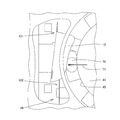
- FIG. 1 is a front view of a partition plate used in a tablet cassette according to Embodiment 1 of the present invention.
- FIG. 2 is a plan view of the partition plate viewed from the direction indicated by the arrow II in FIG.
- FIG. 3 is a rear view of the partition plate viewed from the direction indicated by arrow III in FIG.
- FIG. 4 is a bottom view of the partition plate viewed from the direction indicated by the arrow IV in FIG.
- FIG. 5 is a right side view of the partition plate viewed from the direction indicated by the arrow V in FIG.
- FIG. 6 is a left side view of the partition plate viewed from the direction indicated by the arrow VI in FIG.
- FIG. 7 is a sectional view taken along line VII-VII in FIG.
- FIG. 8 is a sectional view taken along line VIII-VIII in FIG.
- FIG. 9 is a perspective view of the partition plate shown in FIG.
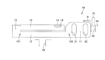
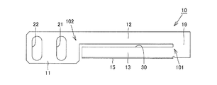
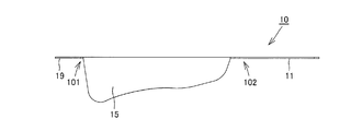
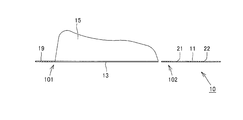
- partition plate 10 used in the tablet cassette according to the first embodiment includes an attachment portion 11 attached to the tablet cassette, a main body portion 12 connected to the attachment portion 11, and a main body. It has the extension part 13 extended in parallel with the part 12, the connection part 19 which connects the main-body part 12 and the extension part 13, and the cover part 15 provided in the extension part 13. As shown in FIG. Two holes 21 and 22 are provided in the attachment portion 11. Both of the two holes 21 and 22 have a long hole shape, and have a shape capable of changing the position of the partition plate 10 with respect to the tablet cassette.
- the vicinity of the boundary between the main body portion 12 and the attachment portion 11 is the second fulcrum 102.
- the main body 12 can swing around the second fulcrum 102. As the main body 12 swings, the main body 12 and the extending portion 13 connected to the main body 12 swing.
- the vicinity of the connecting portion 19 that connects the main body portion 12 and the extending portion 13 is the first fulcrum 101.
- the extending part 13 can swing around the first fulcrum 101.
- a slit 30 is provided between the main body portion 12 and the extending portion 13. By increasing the length of the slit 30, the length of the connecting portion 19 is shortened.
- the length of the connecting portion 19 in the slit direction is related to the swinging motion of the extending portion 13 around the first fulcrum 101. If the length of the connecting portion 19 in the slit 30 direction is long, the strength of the connecting portion 19 is increased. Therefore, it becomes difficult for the extending portion 13 to swing around the first fulcrum 101.
- the window 14 is a window for viewing the position of a tablet (including a capsule) to be sent, and the partition plate 10 is attached so as to be an optimum position with respect to the position of the tablet sent by the rotor.
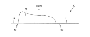
- the lid portion 15 is formed in a plate shape, and the edge that comes into contact with the tablet flowing from the attachment portion 11 side is curved so that the tablet moves smoothly.
- the shape is such that a large mountain exists on the first fulcrum 101 side and a small mountain exists on the second fulcrum 102 side.
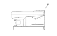
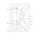
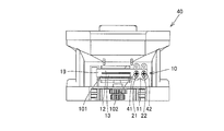
- FIG. 10 is a front view of the tablet cassette according to the first embodiment.
- FIG. 11 is a bottom view of the tablet cassette shown in FIG. 10
- FIG. 12 is a right side view of the tablet cassette shown in FIG.
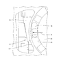
- the partition plate 10 is attached to the front surface of the tablet cassette 40 by screws 41 and 42.
- the holes 21 and 22 have a long hole shape, and the attachment position of the partition plate 10 can be changed in the vertical direction shown in FIG. Thereby, it is possible to change the attachment position of the partition plate 10 according to the kind (size) of the tablet accommodated in the tablet cassette 40.
- the tablet cassette 40 is provided with a gear 43 for rotating the rotor. This gear 43 is driven from the outside.
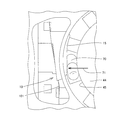
- FIG. 13 is a perspective view showing a tablet counter in which the tablet cassette according to the present invention is used.
- a tablet cassette 40 and a cassette base 50 are provided on a tablet counter 60.
- the tablets stored in the tablet cassette 40 are sent to the tablet counter 60 via the cassette base 50, and the number is counted in the tablet counter 60.
- the tablet cassette 40 is attached to the tablet counter 60
- the present invention is not limited to this, and the tablet cassette 40 may be attached to the packaging machine together with the cassette base 50.
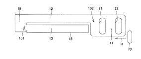
- FIG. 14 is a front view showing the movement of the tablet in the tablet cassette.
- FIG. 15 is a plan view showing the movement of the tablet in the tablet cassette.
- the tablet 44 is discharged from the discharge hole 48 by rotating the rotor 44.
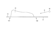
- the rotor 44 is provided with a groove 45, and the tablet 70 fitted in the groove 45 passes through the lower side of the lid portion 15 and is discharged from the discharge hole 48.
- the tablet 70 partially protruding from the groove 45 and protruding upward is fed by the rotor 44 in the direction indicated by the arrow R, the tablet comes into contact with the lid portion 15.
- FIG. 16 is a diagram showing the partition plate immediately before coming into contact with the tablet.
- the tablet 70 may be arranged so as to protrude from the groove 45. When the tablet 70 is fed by the rotor 44 in this state, the tablet 70 approaches the lid portion 15.
- FIG. 17 is a view showing the partition plate in a state where the tablet starts to contact the lid.
- tablet 70 contacts lid portion 15
- tablet 70 applies a force to lid portion 15 in the direction indicated by arrow 71. Due to this force, the lid portion 15 swings around the first fulcrum 101. As a result, the position of the lid portion 15 is changed from the position shown in FIG. 16, and the gap between the rotor 44 and the lid portion 15 is increased. Then, the tablet 70 is sent by the rotor 44.
- FIG. 18 is a view showing the partition plate in a state where the tablet is further fed from FIG. As shown in FIG. 18, the tablet 70 is further fed, and the tablet 70 is positioned approximately at the midpoint between the first fulcrum 101 and the second fulcrum 102. In this case, the lid portion 15 swings around both the first fulcrum 101 and the second fulcrum 102, and the lid portion 15 is moved to the left substantially parallel to the position shown in FIG.
- FIG. 19 is a view showing the partition plate in a state where the tablet is further fed from FIG. Referring to FIG. 19, when the tablet 70 is further fed, the tablet 70 applies a force to the first fulcrum 101 side portion of the lid portion 15 as indicated by an arrow 71. As a result, the lid portion 15 swings around the second fulcrum 102. A portion 15 a of the lid 15 that is not in contact with the tablet 70 covers a part of the groove 45.
- FIG. 20 is a view showing the partition plate after the tablet has passed. Referring to FIG. 20, if lid 15 and tablet 70 are not in contact with each other, lid 15 is returned to the normal position.
- the tablet cassette 40 includes a main body 49 for storing the tablet 70, a rotor 44 as a feeding member provided with a groove 45 for receiving the tablet 70 stored in the main body 49, and a main body. 49.
- a partition plate 10 including a main body portion 12 and an extension portion 13 as elastic portions attached to 49, and a lid portion 15 attached to the main body portion 12 and capable of closing at least a part of the opening of the groove 45. Is provided. Under the lid portion 15, a discharge hole 48 is provided in the main body 49, and when the tablet 70 received in the groove 45 reaches the bottom of the lid portion 15, the tablet 70 falls downward from the discharge hole 48, and partly from the groove 45. The tablet 70 sent in a state of protruding protrudes from the lid portion 15.
- the main body portion 12 is a first fulcrum 101 serving as a fulcrum of movement in which the contact portion of the lid portion 15 with the tablet 70 is pressed from the tablet 70 in a state in which the lid portion 15 and the tablet 70 are in contact with each other. And the second fulcrum in which the contact portion of the lid portion 15 with the tablet 70 is pressed and moved from the tablet 70 after the operation of the main body 12 and the extending portion 13 with the first fulcrum as a fulcrum is completed. 102.
- the first fulcrum 101 is located downstream of the second fulcrum 102 in the flow of the tablet 70.
- the elastic part has a main body part 12 as a first piece and an extension part 13 as a second piece that extend in the direction in which the tablets are fed, and the main body part 12 is attached to the main body 49 on one end side and extends.
- the portion 13 is attached to the lid portion 15, and the main body portion 12 and the extending portion 13 are connected to each other on the other end side.
- the partition plate 10 is manufactured by bending a metal plate.
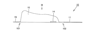
- FIG. 21 is a perspective view of a partition plate according to a comparative example.
- FIG. 21 is different from the partition plate according to the first embodiment in that an extending portion is interposed between the main body portion 12 and the lid portion 15 in that the lid portion 15 is directly attached to the main body portion 12.
- FIG. 22 is a diagram showing a contact state with the tablet on the partition plate according to the comparative example.
- the tablet 70 is fed to the rotor 44. In this case, if the position of the tablet 70 is inappropriate, the tablet 70 contacts the lid portion 15.
- FIG. 23 is a view showing a partition plate according to a comparative example in a state where the tablet starts to contact the lid. As shown in FIG. 23, when the tablet 70 comes into contact with the lid portion 15, the lid portion 15 largely swings around the first fulcrum 101.
- FIG. 24 is a diagram showing a partition plate according to a comparative example in a state where tablets are further fed from FIG. Referring to FIG. 24, when tablet 70 is further fed, lid portion 15 swings larger. At this time, the lid portion 15 is in a state of not substantially covering the upper portion of the discharge hole 48, and the discharge hole 48 is opened. When the upper portion of the discharge hole 48 is opened, the tablet may fall into the groove 45 and the tablet may fall from the discharge hole 48.
- the tablet 70 is always covered while the tablet 70 is in contact with the lid 15 as compared with the comparative example.
- a part of the portion 15 covers the groove 45 of the rotor.
- the lid portion 15 easily swings. Thereby, it can prevent that an excessive burden is applied to a tablet.
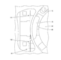
- FIG. 25 is a front view of a partition plate used in the tablet cassette according to the second embodiment of the present invention.
- FIG. 26 is a plan view of the partition plate viewed from the direction indicated by arrow XXVI in FIG.
- FIG. 27 is a rear view of the partition plate viewed from the direction indicated by the arrow XXVII in FIG.
- FIG. 28 is a bottom view of the partition plate viewed from the direction indicated by the arrow XXVIII in FIG.
- FIG. 29 is a right side view of the partition plate viewed from the direction indicated by the arrow XXIX in FIG.
- FIG. 30 is a left side view of the partition plate viewed from the direction indicated by arrow XXX in FIG.
- FIG. 31 is a cross-sectional view taken along line XXXI-XXXI in FIG. 32 is a perspective view of the partition plate shown in FIG.
- FIG. 33 is a front view of the tablet cassette according to the second embodiment.
- FIG. 34 is a front view showing the movement of the tablet in the tablet cassette.
- FIG. 35 is a plan view showing the movement of the tablet in the tablet cassette.
- partition plate 10 used in the tablet cassette according to the second embodiment includes an attachment portion 11 attached to the tablet cassette, a main body portion 12 connected to attachment portion 11, and a main body.
- An extension part 13 extending in parallel with the part 12, a connection part 19 for connecting the main body part 12 and the extension part 13, and a lid part 15 provided on the extension part 13, and the main body part 12 on the upper side.
- the extending portion 13 and the lid portion 15 are provided on the lower side.
- the tablet cassette 40 according to the second embodiment configured as described above has the same effect as the tablet cassette 40 according to the first embodiment.
- FIG. 36 is a plan view of a tablet cassette according to Embodiment 3 of the present invention.
- the tablet cassette according to the third embodiment is the same as the tablet cassette according to the first embodiment in that the first fulcrum 101 and the second fulcrum 102 are constituted by coil springs 81 and 82. Different.
Landscapes
- Physics & Mathematics (AREA)
- General Physics & Mathematics (AREA)
- Engineering & Computer Science (AREA)
- Health & Medical Sciences (AREA)
- Mechanical Engineering (AREA)
- General Health & Medical Sciences (AREA)
- Life Sciences & Earth Sciences (AREA)
- Animal Behavior & Ethology (AREA)
- Pharmacology & Pharmacy (AREA)
- Public Health (AREA)
- Veterinary Medicine (AREA)
- Quality & Reliability (AREA)
- Chemical & Material Sciences (AREA)
- Medicinal Chemistry (AREA)
- Medical Preparation Storing Or Oral Administration Devices (AREA)
- Basic Packing Technique (AREA)
Abstract
Description
好ましくは、弾性部は、互いに錠剤が送られる方向に延びる第一および第二片を有し、第一片が一方端側で本体に取付けられ、第二片が蓋部に取付けられ、第一および第二片は他方端側で互いに接続される。
この発明の別の局面に従った錠剤カセッターは、錠剤を収納するための本体と、本体に収納された錠剤を受け入れるための溝が設けられた送り部材と、本体に取付けられる弾性部と、弾性部に取付けられて溝の開口部の少なくとも一部分を塞ぐことが可能な蓋部とを含む仕切部材とを備え、蓋部下では本体に孔が開いており、溝に収納されて送られた錠剤は蓋部下に達すると本体の孔から下部へ落下し、溝から一部分がはみ出した状態で送られた錠剤は蓋部と当接し、弾性部は、互いに錠剤が送られる方向に延びる第一および第二片を有し、第一片が錠剤の流れの上流側の一方端側で本体に取付けられ、第二片が蓋部に取付けられ、第一および第二片は下流側の他方端側で互いに接続される。
図1は、この発明の実施の形態1に従った錠剤カセッターで用いられる仕切板の正面図である。図2は、図1中の矢印IIで示す方向から見た仕切板の平面図である。図3は、図2中の矢印IIIで示す方向から見た仕切板の背面図である。図4は、図1中の矢印IVで示す方向から見た仕切板の底面図である。図5は、図1中の矢印Vで示す方向から見た仕切板の右側面図である。図6は、図1中の矢印VIで示す方向から見た仕切板の左側面図である。図7は、図1中のVII-VII線に沿った断面図である。図8は、図1中のVIII-VIII線に沿った断面図である。図9は、図1で示す仕切板の斜視図である。
(実施の形態2)
図25は、この発明の実施の形態2に従った錠剤カセッターで用いられる仕切板の正面図である。図26は、図25中の矢印XXVIで示す方向から見た仕切板の平面図である。図27は、図26中の矢印XXVIIで示す方向から見た仕切板の背面図である。図28は、図25中の矢印XXVIIIで示す方向から見た仕切板の底面図である。図29は、図25中の矢印XXIXで示す方向から見た仕切板の右側面図である。図30は、図25中の矢印XXXで示す方向から見た仕切板の左側面図である。図31は、図25中のXXXI-XXXI線に沿った断面図である。図32は、図25で示す仕切板の斜視図である。図33は、実施の形態2に従った錠剤カセッターの正面図である。図34は、錠剤カセッター内での錠剤の動きを示す正面図である。図35は、錠剤カセッター内での錠剤の動きを示す平面図である。
図36は、この発明の実施の形態3に従った錠剤カセッターの平面図である。図36を参照して、実施の形態3に従った錠剤カセッターでは、第一支点101および第二支点102がコイルバネ81,82で構成されている点で、実施の形態1に従った錠剤カセッターと異なる。
Claims (5)
- 錠剤(70)を収納するための本体(49)と、
前記本体に収納された錠剤を受け入れるための溝が設けられた送り部材(44)と、
前記本体に取付けられる弾性部(12)と、前記弾性部に取付けられて前記溝の開口部の少なくとも一部分を塞ぐことが可能な蓋部(15)とを含む仕切部材(10)とを備え、
前記蓋部下では前記本体に孔が開いており、前記溝に収納されて送られた錠剤は前記蓋部下に達すると前記本体の孔から下部へ落下し、
前記溝から一部分がはみ出した状態で送られた錠剤は前記蓋部と当接し、
前記弾性部は、前記蓋部と錠剤との当接が開始した状態において前記蓋部のうち前記錠剤との当接部分が錠剤から押圧されて移動する動作の支点となる第一支点(101)と、前記第一支点を支点とした前記弾性部の動作が終了した後に前記蓋部のうち前記錠剤との当接部分が前記錠剤から押圧されて移動する動作の支点となる第二支点(102)とを有する、錠剤カセッター。 - 前記第一支点は、前記第二支点よりも前記錠剤の流れの下流側に位置している、請求項1に記載の錠剤カセッター。
- 前記弾性部は、互いに錠剤が送られる方向に延びる第一および第二片を有し、前記第一片が一方端側で前記本体に取付けられ、前記第二片が前記蓋部に取付けられ、前記第一および第二片は他方端側で互いに接続される、請求項2に記載の錠剤カセッター。
- 前記仕切部材は金属板を曲げることで製造される、請求項3に記載の錠剤カセッター。
- 錠剤を収納するための本体(49)と、
前記本体に収納された錠剤を受け入れるための溝が設けられた送り部材(44)と、
前記本体に取付けられる弾性部(12)と、前記弾性部に取付けられて前記溝の開口部の少なくとも一部分を塞ぐことが可能な蓋部(15)とを含む仕切部材(10)とを備え、
前記蓋部下では前記本体に孔が開いており、前記溝に収納されて送られた錠剤は前記蓋部下に達すると前記本体の孔から下部へ落下し、
前記溝から一部分がはみ出した状態で送られた錠剤は前記蓋部と当接し、
前記弾性部は、互いに錠剤が送られる方向に延びる第一および第二片を有し、前記第一片が錠剤の流れの上流側の一方端側で前記本体に取付けられ、前記第二片が前記蓋部に取付けられ、前記第一および第二片は下流側の他方端側で互いに接続される、錠剤カセッター。
Priority Applications (7)
| Application Number | Priority Date | Filing Date | Title |
|---|---|---|---|
| CA2825902A CA2825902A1 (en) | 2011-02-01 | 2012-01-11 | Tablet cassette |
| AU2012212820A AU2012212820B2 (en) | 2011-02-01 | 2012-01-11 | Tablet cassette |
| EP12742013.1A EP2671564A4 (en) | 2011-02-01 | 2012-01-11 | CASSETTE OF TABLETS |
| HK14101924.3A HK1188709B (en) | 2011-02-01 | 2012-01-11 | Tablet cassette |
| US13/996,326 US9457950B2 (en) | 2011-02-01 | 2012-01-11 | Tablet cassette |
| CN201280007373.0A CN103338739B (zh) | 2011-02-01 | 2012-01-11 | 片剂盒 |
| KR1020137020421A KR101735878B1 (ko) | 2011-02-01 | 2012-01-11 | 정제 카세터 |
Applications Claiming Priority (2)
| Application Number | Priority Date | Filing Date | Title |
|---|---|---|---|
| JP2011-019676 | 2011-02-01 | ||
| JP2011019676A JP5957747B2 (ja) | 2011-02-01 | 2011-02-01 | 錠剤カセッター |
Publications (1)
| Publication Number | Publication Date |
|---|---|
| WO2012105286A1 true WO2012105286A1 (ja) | 2012-08-09 |
Family
ID=46602507
Family Applications (1)
| Application Number | Title | Priority Date | Filing Date |
|---|---|---|---|
| PCT/JP2012/050358 Ceased WO2012105286A1 (ja) | 2011-02-01 | 2012-01-11 | 錠剤カセッター |
Country Status (8)
| Country | Link |
|---|---|
| US (1) | US9457950B2 (ja) |
| EP (1) | EP2671564A4 (ja) |
| JP (1) | JP5957747B2 (ja) |
| KR (1) | KR101735878B1 (ja) |
| CN (1) | CN103338739B (ja) |
| AU (1) | AU2012212820B2 (ja) |
| CA (1) | CA2825902A1 (ja) |
| WO (1) | WO2012105286A1 (ja) |
Cited By (1)
| Publication number | Priority date | Publication date | Assignee | Title |
|---|---|---|---|---|
| CN103910143A (zh) * | 2013-01-02 | 2014-07-09 | 因福皮亚有限公司 | 用于药剂分配设备的片剂药筒 |
Families Citing this family (7)
| Publication number | Priority date | Publication date | Assignee | Title |
|---|---|---|---|---|
| EP2572995B1 (en) * | 2010-05-17 | 2016-07-06 | Yuyama Mfg. Co., Ltd. | Tablet cassette |
| EP2664316B1 (en) * | 2011-01-14 | 2020-03-25 | Yuyama Mfg. Co., Ltd. | Tablet cassette |
| JP6000195B2 (ja) * | 2013-07-03 | 2016-09-28 | 株式会社トーショー | 錠剤カセット |
| US9663260B2 (en) * | 2014-01-31 | 2017-05-30 | Yuyama Mfg. Co., Ltd. | Drug feeder |
| JP6391063B2 (ja) * | 2015-06-04 | 2018-09-19 | 株式会社トーショー | 薬剤カセット用仕切板 |
| JP6569911B2 (ja) * | 2016-07-27 | 2019-09-04 | 株式会社トーショー | 錠剤カセット |
| EP3389022A1 (de) * | 2017-04-11 | 2018-10-17 | Becton Dickinson Rowa Germany GmbH | Vorratsbehälter für eine vorrats- und abgabestation |
Citations (6)
| Publication number | Priority date | Publication date | Assignee | Title |
|---|---|---|---|---|
| JPS50143953A (ja) * | 1974-05-08 | 1975-11-19 | ||
| JPS5492719U (ja) * | 1977-12-14 | 1979-06-30 | ||
| JPH0939910A (ja) * | 1995-08-02 | 1997-02-10 | Yuyama Seisakusho:Kk | 錠剤フィーダ |
| JPH09266940A (ja) | 1996-04-02 | 1997-10-14 | Takazono Sangyo Kk | 錠剤等の薬剤選択供給装置用の薬剤収容容器 |
| JP2001176955A (ja) * | 1999-10-29 | 2001-06-29 | Boc Group Inc:The | 傷つきやすい基板のためのばねクリップ |
| US20080029535A1 (en) * | 2006-08-02 | 2008-02-07 | Jun Ho Kim | Tablet cassette with silicon partition |
Family Cites Families (10)
| Publication number | Priority date | Publication date | Assignee | Title |
|---|---|---|---|---|
| US3128011A (en) * | 1961-09-20 | 1964-04-07 | Howard W Bleiman | Coin operated vending machine |
| JP4351016B2 (ja) | 2003-10-01 | 2009-10-28 | 株式会社湯山製作所 | 錠剤カセット |
| US7857162B2 (en) * | 2004-03-31 | 2010-12-28 | Yuyama Mfg. Co., Ltd. | Tablet feeder |
| JP2006230763A (ja) * | 2005-02-25 | 2006-09-07 | Yuyama Manufacturing Co Ltd | 錠剤充填装置 |
| KR100800290B1 (ko) | 2006-11-01 | 2008-02-01 | (주)제이브이엠 | 약제 자동 포장기용 카세트 장치 |
| US8616409B2 (en) * | 2008-01-16 | 2013-12-31 | Parata Systems, Llc | Devices for dispensing objects useful in system and method for dispensing |
| EP3064190B1 (en) * | 2008-09-18 | 2018-11-21 | Yuyama Mfg. Co., Ltd. | Tablet feeder |
| CN102356025B (zh) * | 2009-04-17 | 2015-01-21 | 株式会社汤山制作所 | 药剂供给装置和药剂发放装置 |
| EP2572995B1 (en) * | 2010-05-17 | 2016-07-06 | Yuyama Mfg. Co., Ltd. | Tablet cassette |
| KR101449717B1 (ko) * | 2013-01-02 | 2014-10-15 | 주식회사 인포피아 | 약제 포장장치용 정제 카트리지 |
-
2011
- 2011-02-01 JP JP2011019676A patent/JP5957747B2/ja active Active
-
2012
- 2012-01-11 KR KR1020137020421A patent/KR101735878B1/ko not_active Expired - Fee Related
- 2012-01-11 WO PCT/JP2012/050358 patent/WO2012105286A1/ja not_active Ceased
- 2012-01-11 AU AU2012212820A patent/AU2012212820B2/en not_active Ceased
- 2012-01-11 CA CA2825902A patent/CA2825902A1/en not_active Abandoned
- 2012-01-11 EP EP12742013.1A patent/EP2671564A4/en not_active Withdrawn
- 2012-01-11 US US13/996,326 patent/US9457950B2/en not_active Expired - Fee Related
- 2012-01-11 CN CN201280007373.0A patent/CN103338739B/zh not_active Expired - Fee Related
Patent Citations (6)
| Publication number | Priority date | Publication date | Assignee | Title |
|---|---|---|---|---|
| JPS50143953A (ja) * | 1974-05-08 | 1975-11-19 | ||
| JPS5492719U (ja) * | 1977-12-14 | 1979-06-30 | ||
| JPH0939910A (ja) * | 1995-08-02 | 1997-02-10 | Yuyama Seisakusho:Kk | 錠剤フィーダ |
| JPH09266940A (ja) | 1996-04-02 | 1997-10-14 | Takazono Sangyo Kk | 錠剤等の薬剤選択供給装置用の薬剤収容容器 |
| JP2001176955A (ja) * | 1999-10-29 | 2001-06-29 | Boc Group Inc:The | 傷つきやすい基板のためのばねクリップ |
| US20080029535A1 (en) * | 2006-08-02 | 2008-02-07 | Jun Ho Kim | Tablet cassette with silicon partition |
Non-Patent Citations (1)
| Title |
|---|
| See also references of EP2671564A4 * |
Cited By (3)
| Publication number | Priority date | Publication date | Assignee | Title |
|---|---|---|---|---|
| CN103910143A (zh) * | 2013-01-02 | 2014-07-09 | 因福皮亚有限公司 | 用于药剂分配设备的片剂药筒 |
| EP2752181A3 (en) * | 2013-01-02 | 2015-01-21 | Infopia Co., Ltd. | Tablet cartridge for medication dispensing apparatus |
| US9181017B2 (en) | 2013-01-02 | 2015-11-10 | Infopia Co., Ltd. | Tablet cartridge for medication dispensing apparatus |
Also Published As
| Publication number | Publication date |
|---|---|
| CN103338739B (zh) | 2015-01-21 |
| EP2671564A1 (en) | 2013-12-11 |
| HK1188709A1 (zh) | 2014-05-16 |
| AU2012212820A1 (en) | 2013-08-01 |
| JP2012157569A (ja) | 2012-08-23 |
| AU2012212820B2 (en) | 2015-09-24 |
| CA2825902A1 (en) | 2012-08-09 |
| KR20140006864A (ko) | 2014-01-16 |
| US9457950B2 (en) | 2016-10-04 |
| CN103338739A (zh) | 2013-10-02 |
| US20140084020A1 (en) | 2014-03-27 |
| EP2671564A4 (en) | 2016-10-12 |
| KR101735878B1 (ko) | 2017-05-15 |
| JP5957747B2 (ja) | 2016-07-27 |
Similar Documents
| Publication | Publication Date | Title |
|---|---|---|
| WO2012105286A1 (ja) | 錠剤カセッター | |
| CN104249565B (zh) | 热敏打印机 | |
| CN103842255B (zh) | 药剂供给装置 | |
| JP5260658B2 (ja) | テーピングヘッド | |
| CN104070791A (zh) | 记录装置 | |
| CN104602575A (zh) | 用于使用封装体等制备饮料的机器的泡制组件 | |
| JP2005247521A (ja) | 給紙装置 | |
| JP6142150B2 (ja) | 錠剤カセッター | |
| US9309069B2 (en) | Sheet separating apparatus | |
| HK1188709B (en) | Tablet cassette | |
| CN202623539U (zh) | 开闭装置 | |
| JP6918327B2 (ja) | 錠剤カセット | |
| KR101449718B1 (ko) | 약제 포장장치용 커터 | |
| JP2011211597A (ja) | 画像読取装置 | |
| US9019574B2 (en) | Sheet feeding apparatus | |
| JP2011092349A (ja) | 調剤装置の薬剤ストック構造 | |
| JP5436258B2 (ja) | 計量装置 | |
| KR102741595B1 (ko) | 다열 간격 가변형 알약 제포기 | |
| CN213123176U (zh) | 智能包装茶叶出货机构 | |
| JP7418265B2 (ja) | コンパクト容器 | |
| JP6830642B2 (ja) | 薬剤供給装置 | |
| KR101498204B1 (ko) | 자동 개폐 기능을 갖는 약제 포장 장치용 카트리지 | |
| JP5430347B2 (ja) | 調剤装置の薬剤ストック構造 | |
| JP2011043929A (ja) | 直積み式自動販売機の商品収納装置 | |
| JP5081657B2 (ja) | ストロー供給装置 |
Legal Events
| Date | Code | Title | Description |
|---|---|---|---|
| 121 | Ep: the epo has been informed by wipo that ep was designated in this application |
Ref document number: 12742013 Country of ref document: EP Kind code of ref document: A1 |
|
| WWE | Wipo information: entry into national phase |
Ref document number: 13996326 Country of ref document: US |
|
| ENP | Entry into the national phase |
Ref document number: 2825902 Country of ref document: CA |
|
| ENP | Entry into the national phase |
Ref document number: 2012212820 Country of ref document: AU Date of ref document: 20120111 Kind code of ref document: A Ref document number: 20137020421 Country of ref document: KR Kind code of ref document: A |
|
| NENP | Non-entry into the national phase |
Ref country code: DE |
|
| REEP | Request for entry into the european phase |
Ref document number: 2012742013 Country of ref document: EP |
|
| WWE | Wipo information: entry into national phase |
Ref document number: 2012742013 Country of ref document: EP |