WO2012105429A1 - 光ファイバ特性測定装置及び方法 - Google Patents
光ファイバ特性測定装置及び方法 Download PDFInfo
- Publication number
- WO2012105429A1 WO2012105429A1 PCT/JP2012/051754 JP2012051754W WO2012105429A1 WO 2012105429 A1 WO2012105429 A1 WO 2012105429A1 JP 2012051754 W JP2012051754 W JP 2012051754W WO 2012105429 A1 WO2012105429 A1 WO 2012105429A1
- Authority
- WO
- WIPO (PCT)
- Prior art keywords
- optical fiber
- light
- detection signal
- photodetector
- detection
- Prior art date
- Legal status (The legal status is an assumption and is not a legal conclusion. Google has not performed a legal analysis and makes no representation as to the accuracy of the status listed.)
- Ceased
Links
Images



Classifications
-
- G—PHYSICS
- G01—MEASURING; TESTING
- G01M—TESTING STATIC OR DYNAMIC BALANCE OF MACHINES OR STRUCTURES; TESTING OF STRUCTURES OR APPARATUS, NOT OTHERWISE PROVIDED FOR
- G01M11/00—Testing of optical apparatus; Testing structures by optical methods not otherwise provided for
- G01M11/30—Testing of optical devices, constituted by fibre optics or optical waveguides
- G01M11/33—Testing of optical devices, constituted by fibre optics or optical waveguides with a light emitter being disposed at one fibre or waveguide end-face, and a light receiver at the other end-face
-
- G—PHYSICS
- G01—MEASURING; TESTING
- G01M—TESTING STATIC OR DYNAMIC BALANCE OF MACHINES OR STRUCTURES; TESTING OF STRUCTURES OR APPARATUS, NOT OTHERWISE PROVIDED FOR
- G01M11/00—Testing of optical apparatus; Testing structures by optical methods not otherwise provided for
- G01M11/30—Testing of optical devices, constituted by fibre optics or optical waveguides
- G01M11/39—Testing of optical devices, constituted by fibre optics or optical waveguides in which light is projected from both sides of the fiber or waveguide end-face
-
- G—PHYSICS
- G01—MEASURING; TESTING
- G01D—MEASURING NOT SPECIALLY ADAPTED FOR A SPECIFIC VARIABLE; ARRANGEMENTS FOR MEASURING TWO OR MORE VARIABLES NOT COVERED IN A SINGLE OTHER SUBCLASS; TARIFF METERING APPARATUS; MEASURING OR TESTING NOT OTHERWISE PROVIDED FOR
- G01D5/00—Mechanical means for transferring the output of a sensing member; Means for converting the output of a sensing member to another variable where the form or nature of the sensing member does not constrain the means for converting; Transducers not specially adapted for a specific variable
- G01D5/26—Mechanical means for transferring the output of a sensing member; Means for converting the output of a sensing member to another variable where the form or nature of the sensing member does not constrain the means for converting; Transducers not specially adapted for a specific variable characterised by optical transfer means, i.e. using infrared, visible, or ultraviolet light
- G01D5/32—Mechanical means for transferring the output of a sensing member; Means for converting the output of a sensing member to another variable where the form or nature of the sensing member does not constrain the means for converting; Transducers not specially adapted for a specific variable characterised by optical transfer means, i.e. using infrared, visible, or ultraviolet light with attenuation or whole or partial obturation of beams of light
- G01D5/34—Mechanical means for transferring the output of a sensing member; Means for converting the output of a sensing member to another variable where the form or nature of the sensing member does not constrain the means for converting; Transducers not specially adapted for a specific variable characterised by optical transfer means, i.e. using infrared, visible, or ultraviolet light with attenuation or whole or partial obturation of beams of light the beams of light being detected by photocells
- G01D5/353—Mechanical means for transferring the output of a sensing member; Means for converting the output of a sensing member to another variable where the form or nature of the sensing member does not constrain the means for converting; Transducers not specially adapted for a specific variable characterised by optical transfer means, i.e. using infrared, visible, or ultraviolet light with attenuation or whole or partial obturation of beams of light the beams of light being detected by photocells influencing the transmission properties of an optical fibre
- G01D5/35338—Mechanical means for transferring the output of a sensing member; Means for converting the output of a sensing member to another variable where the form or nature of the sensing member does not constrain the means for converting; Transducers not specially adapted for a specific variable characterised by optical transfer means, i.e. using infrared, visible, or ultraviolet light with attenuation or whole or partial obturation of beams of light the beams of light being detected by photocells influencing the transmission properties of an optical fibre using other arrangements than interferometer arrangements
- G01D5/35341—Sensor working in transmission
- G01D5/35348—Sensor working in transmission using stimulated emission to detect the measured quantity
Definitions
- the present invention relates to an optical fiber characteristic measuring apparatus and method. This application claims priority based on Japanese Patent Application No. 2011-018951 filed on January 31, 2011, the contents of which are incorporated herein by reference.
- an optical fiber characteristic measuring device is designed to make continuous light or pulsed light incident on an optical fiber, and to receive scattered light or reflected light generated in the optical fiber, thereby causing temperature distribution, strain distribution, etc. in the longitudinal direction of the optical fiber. It is a device that measures the characteristics of.
- the scattered light or the reflected light that is received changes in accordance with a physical quantity (for example, temperature or stress) that affects the optical fiber, so the optical fiber itself is used as a sensor.
- Patent Document 1 frequency-modulated continuous light (pump light and probe light) is incident from both ends of the optical fiber to form a periodic correlation peak between the pump light and the probe light along the optical fiber.
- An optical fiber characteristic measuring apparatus that measures the characteristic of an optical fiber by utilizing the property that the probe light is amplified by the stimulated Brillouin scattering phenomenon only at the position of the correlation peak is disclosed.
- This optical fiber characteristic measuring apparatus can measure the characteristic in the longitudinal direction of the optical fiber by receiving the probe light amplified at each position while changing the position of the correlation peak in the optical fiber.
- frequency-modulated continuous light (probe light) and pulsed light (pump light) are incident from one end and the other end of the optical fiber, respectively, to the position of the pump light propagating through the optical fiber. Correlation peaks are sequentially generated accordingly, and only light from the vicinity of the measurement point (stimulated Brillouin scattered light) of the light emitted from the optical fiber is obtained to measure the characteristics of the optical fiber at the measurement point.
- An apparatus for measuring fiber characteristics is disclosed. This optical fiber characteristic measuring device adjusts the modulation frequency of the probe light and the pump light and the light reception timing of the light emitted from the optical fiber, and moves the measurement point, so that an arbitrary position in the longitudinal direction of the optical fiber can be moved. Characteristics can be measured.
- the optical fiber characteristic measuring device disclosed in Patent Document 2 includes a timing adjuster in front of a photodetector that receives light emitted from the optical fiber, and the light emitted from the optical fiber is measured. By cutting out with the timing adjuster, only the light from the vicinity of the measurement point is received by the photodetector.
- a timing adjuster is realized by, for example, an optical switch using an LN (Lithium-Niobate) modulator using an electro-optic effect (Pockels effect).
- the optical switch can switch between an on state (a state in which light is transmitted) and an off state (a state in which light is blocked) at high speed. For example, light emitted from an optical fiber can be emitted for several nsec. It is also possible to cut out at intervals. Therefore, if such an optical switch is used as a timing adjuster, an optical fiber characteristic measuring apparatus having a high spatial resolution of about 1 cm can be realized.
- the above optical switch has a large insertion loss, has polarization dependency, and is expensive. For this reason, in the future, there is a possibility that the following problems will occur when the spatial resolution of the optical fiber characteristic measuring device is improved and the cost is reduced.
- the above optical switch has polarization dependency in which the intensity of transmitted light varies according to the polarization direction of incident light. It is also a characteristic that the insertion loss of the optical switch varies depending on the wave direction. For this reason, when said optical switch tries to improve the spatial resolution of an optical fiber characteristic measuring apparatus, while being a factor which worsens measurement accuracy, it will become a factor which worsens measurement stability and reproducibility. There's a problem.
- the present invention has been made in view of the above circumstances, and an optical fiber characteristic measuring apparatus capable of improving spatial resolution and reducing costs without deteriorating measurement accuracy and stability / reproducibility, and It aims to provide a method.
- an optical fiber characteristic measuring apparatus of the present invention includes a light source (11) that emits laser light modulated at a predetermined modulation frequency, and continuous light (L1) and pulse light from the light source.
- the optical fiber characteristic measuring device (1, 2) for measuring the characteristic of the optical fiber using the detection result of the photodetector among the detection signals (D1) output from the photodetector, The detection signal obtained by detecting the light near the measurement point set in the optical fiber is cut out, and the detection signal cut out using the synchronous signals (SY, SY1) having a predetermined period is synchronously detected.
- Sync It is characterized in that it comprises a wave device (18, 30).
- the detection signal obtained by detecting the light in the vicinity of the measurement point set in the optical fiber is cut out, and the synchronization signal having a predetermined cycle is obtained.
- the detection signal cut out by using is detected synchronously.
- the optical fiber characteristic measuring device of the present invention is obtained by the synchronous detector detecting light in the vicinity of the measurement point set in the optical fiber, out of detection signals output from the photodetector.
- the operation period of the timing adjuster is a half of the period of the synchronization signal.
- the optical fiber characteristic measuring apparatus according to the present invention includes an inverter (21b) that outputs an inverted signal obtained by inverting the polarity of the detection signal output from the photodetector, and the photodetector A non-inverter (21a) that outputs a non-inverted signal that does not invert the polarity of the output detection signal, an inverted signal output from the inverter, and a non-inverted signal output from the non-inverter From the switch unit (31) for performing the cut-out by alternately outputting detection signals obtained by detecting light in the vicinity of the measurement point set on the fiber at the timing of output from the photodetector, and from the switch unit And a low-pass filter (24) for filtering the output signal (S1).
- the period in which the pulsed light is incident on the other end of the optical fiber is such that at least the pulsed light reciprocates between one end and the other end of the optical fiber.
- the period is set to twice the time required, and the period of the synchronization signal is the same as the period in which the pulsed light is incident on the other end of the optical fiber.
- laser light modulated at a predetermined modulation frequency is made incident as continuous light (L1) and pulsed light (L2) from one end and the other end of the optical fiber (14), respectively.
- the detection signal output from the photodetector is set in the optical fiber.
- the detection signal obtained by detecting the light in the vicinity of the measurement point is cut out, and the detection signal cut out using the synchronous signal having a predetermined period is synchronously detected.
- the detection signal obtained by detecting the light in the vicinity of the measurement point set in the optical fiber is cut out, and the synchronization signal having a predetermined period Since the detection signal that has been cut out using the signal is synchronously detected, the spatial resolution can be improved and the cost can be reduced without deteriorating the measurement accuracy and stability / reproducibility. There is.
- FIG. 1 is a block diagram showing a main configuration of the optical fiber characteristic measuring apparatus according to the first embodiment of the present invention.
- the optical fiber characteristic measuring apparatus 1 of this embodiment includes a light source 11, an optical splitter 12 (incident means), an optical modulator 13 (incident means), an optical fiber 14, and a pulse modulator 15 (incident means). ), A directional coupler 16 (incident means), a photodetector 17, and a synchronous detector 18, and measures the characteristics of the optical fiber 14 in the longitudinal direction (for example, temperature distribution and strain distribution).
- Light source 11 includes a semiconductor laser 11a and the signal generator 11b, and emits a laser beam modulated with a predetermined modulation frequency f m.
- the semiconductor laser 11a for example, an MQW / DFB / LD (Multi-Quantum Well / Distributed Feed-Back / Laser Diode) that emits laser light having a small spectral width and a narrow spectral width can be used.
- Signal generator 11b outputs a sine wave signal for frequency modulation (the modulation signal) to the semiconductor laser 11a with semiconductor modulates the laser beam emitted from the laser 11a frequency f m.
- the optical splitter 12 splits the laser light emitted from the light source 11 into two branches with an intensity ratio of 1: 1, for example.
- the optical modulator 13 includes a microwave generator 13a and an SSB (Single Side Band) optical modulator 13b, and modulates one laser beam branched by the optical branching unit 12 (
- the sideband (single sideband) with respect to the center frequency of the laser beam is generated by shifting the optical frequency.
- the microwave generator 13a outputs a microwave having a frequency equivalent to a frequency shift given to one laser beam branched by the optical branching device 12.
- the SSB optical modulator 13b generates a single sideband having a frequency difference equal to the frequency of the microwave output from the microwave generator 13a with respect to the center frequency of the input light.
- the frequency of the microwave output from the microwave generator 13a is variable.
- the light modulated by the optical modulator 13 enters the optical fiber 14 from one end of the optical fiber 14 as probe light L1 (continuous light).
- the pulse modulator 15 includes a signal generator 15a and a light intensity modulator 15b, and pulsates the other laser beam branched by the optical branching device 12 to generate pulsed light.
- the signal generator 15a outputs a timing signal that defines the timing for pulsing the laser beam.
- the light intensity modulator 15b is, for example, an EO (Electro-Optic) switch, and pulses the laser light from the optical branching device 12 at a timing defined by a timing signal output from the signal generator 15a.
- the pulse modulator 15 generates pulsed light having a pulse width tpw represented by the following equation (2) at a period T represented by the following equation (1).
- L in the following formulas (1) and (2) is the length of the optical fiber 14 (length from one end to the other end)
- n is the refractive index of the optical fiber 14
- c is the speed of light.
- d m is the spacing of the correlation peaks which is formed in the optical fiber 14
- f m is the modulation frequency of the laser light emitted from the light source 11.
- the period T at which the pulse modulator 15 generates the pulsed light is at least twice the time required for the pulsed light to reciprocate between one end and the other end of the optical fiber 14.
- the directional coupler 16 causes the pulsed laser light output from the pulse modulator 15 to enter the optical fiber 14 from the other end of the optical fiber 14 as pump light L2 (pulse light), and the optical fiber 14 is allowed to enter.
- Light (detection light L11) including the probe light L1 that has been propagated and emitted from the other end of the optical fiber 14 is emitted toward the photodetector 17. Note that the intensity of the detection light L11 is influenced by the stimulated Brillouin scattering phenomenon that occurs in the optical fiber 14.
- the photodetector 17 includes a highly sensitive light receiving element such as an avalanche photo diode, for example, and the detection light L11 (light emitted from the other end of the optical fiber 14 and transmitted through the directional coupler 16). Is detected (received) and a detection signal D1 is output.
- the photodetector 17 includes an optical wavelength filter in addition to the light receiving element described above, and a low-frequency side wave from the detection light L11 to the probe light L1. Select only the band and detect its power.
- the SSB optical modulator 13b since the SSB optical modulator 13b is used, the above optical wavelength filter can be omitted.
- the cost is increased by providing the optical wavelength filter, unnecessary frequency components can be suppressed, so that the measurement accuracy can be further improved.
- the synchronous detector 18 includes a timing adjuster 18a and a lock-in amplifier 18b (synchronous detector), and performs synchronous detection of the detection signal D1 output from the photodetector 17.
- the synchronous detector 18 includes a measurement point set in the optical fiber 14 (a point where characteristics are to be measured) in the detection signal D1 output from the photodetector 17 and a guided Brillouin generated in the vicinity thereof.
- a detection signal obtained by detecting light including scattered light is cut out, and the detection signal D2 cut out using a synchronous signal SY (see FIGS. 2 and 4) having a predetermined period is synchronously detected.
- the timing adjuster 18a is realized by, for example, an electrical switch (high-speed analog switch) that can switch between an ON state (a state in which the detection signal D1 is passed) and an OFF state (a state in which the detection signal D1 is blocked) at high speed.
- the This timing adjuster 18a is obtained by detecting light including stimulated Brillouin scattered light generated at and near the measurement point set in the optical fiber 14 from the detection signal D1 output from the photodetector 17. The detection signal is cut out by passing the detection signal.
- the operation cycle of the timing adjuster 18a is set to a cycle that is half the cycle of the synchronization signal SY.
- the timing adjuster 18a can cut out the detection signal D1 at a time interval of about several nsec and has a low loss (for example, 1 dB or less). If the detection signal can be cut out at a time interval of about several nsec, a high spatial resolution of 1 cm or less can be realized, and if the loss is low, the S / N ratio does not drop significantly, so that the measurement accuracy Can be improved. Further, by using an electrical switch as the timing adjuster 18a, it is possible to reduce the size and cost, and since it does not have polarization dependency like an optical switch, it may cause deterioration in stability and reproducibility. Furthermore, it is possible to measure in a wide temperature range of about ⁇ 40 to + 80 ° C.
- the lock-in amplifier 18b synchronously detects the detection signal D2 (detection signal cut out by the timing adjuster 18a) that has passed through the timing adjuster 18a using the synchronization signal SY described above.
- the cycle of the synchronization signal SY is the same as the cycle in which the pump light L2 is incident on the other end of the optical fiber 14 (at least the pulsed light reciprocates between one end and the other end of the optical fiber 14). Is set to be twice the time required for the
- FIG. 2 is a block diagram showing a main configuration of a lock-in amplifier provided in the optical fiber characteristic measuring apparatus according to the first embodiment of the present invention.
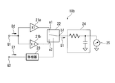
- the lock-in amplifier 18b includes a non-inverter 21a, an inverter 21b, a switch unit 22, a phase shifter 23, a low-pass filter 24, and a DC voltmeter 25, and is input to the synchronization signal input terminal Q2.
- the detection signal D2 input to the signal input terminal Q1 is synchronously detected using the synchronization signal SY.
- the non-inverter 21a outputs the detection signal D2 input to the signal input terminal Q1 as it is without inverting the polarity.
- the inverter 21b inverts the polarity of the detection signal D2 input to the signal input terminal Q1. Output. That is, the non-inverter 21a outputs a non-inverted signal that does not invert the polarity of the detection signal D2, and the inverter 21b outputs an inverted signal in which the polarity of the detection signal D2 is inverted.
- the switch unit 22 includes an input terminal a1 to which the output terminal of the non-inverter 21a is connected, an input terminal a2 to which the output terminal of the inverter 21b is connected, and an output terminal b1 to which the low-pass filter 24 is connected. Based on the synchronization signal SY via the phase shifter 23, the connection between the input terminals a1 and a2 and the output terminal b1 is switched.
- the phase shifter 23 adjusts the phase by changing the phase of the synchronization signal SY input to the synchronization signal input terminal Q2.
- the low-pass filter 24 performs filtering of the output signal S1 output from the output terminal b1 of the switch unit 22. Specifically, the low frequency component (frequency component lower than the cut-off frequency) of the output signal S1 is allowed to pass, and the high frequency component equal to or higher than the cut-off frequency is cut off.
- the DC voltmeter 25 measures the voltage value (DC voltage value) of the signal output from the low-pass filter 24.
- the laser light frequency-modulated at a modulation frequency f m is emitted from the light source 11 in the optical splitter 12.
- One laser beam branched by the optical splitter 12 enters the optical modulator 13 and is modulated by the SSB optical modulator 13b, thereby generating a single sideband with respect to the center frequency of the laser light.
- Laser light (continuous light) having a single sideband emitted from the optical modulator 13 enters the optical fiber 14 from one end of the optical fiber 14 as probe light L1.
- the other laser beam branched by the optical branching device 12 enters the pulse modulator 15 and is pulsed by being intensity-modulated by the light intensity modulator 15b.
- the pulsed light having the pulse width shown in the above-described equation (2) is generated with the period T shown in the above-described (1).
- This pulsed light enters the optical fiber 14 from the other end of the optical fiber 14 through the directional coupler 16 as pump light L2.
- FIG. 3 is a diagram illustrating a state in which a correlation peak occurs in the optical fiber with the progress of the pump light.
- FIG. 3 only five correlation peaks P0 to P4 are shown in order to avoid complication of illustration.
- the pump light L2 is shown passing through the vicinity of the correlation peak P2.
- correlation peaks P0 and P1 indicated by broken lines are correlation peaks that have passed in the past, and correlation peaks P3 and P4 are correlation peaks that will pass from now on as the pump light L2 advances.
- the distance of the correlation peaks d m is expressed by the following equation (3).
- d m (c / n) / (2 ⁇ f m ) (3)
- the generation position of the zero-order correlation peak P0 generated in the optical path difference becomes zero position of the probe light L1 and the pump light L2 can not be moved even by changing the modulation frequency f m.
- the generation position of the zeroth-order correlation peak P ⁇ b> 0 is set to be outside the optical fiber 14.
- the probe light L1 obtains a gain (gain) due to stimulated Brillouin amplification by the pump light L2.
- a Brillouin gain spectrum having the shape of a Lorentz function having a Brillouin frequency shift ⁇ B as the center frequency ( A spectrum called BGS) is obtained. It is known that this Brillouin frequency shift ⁇ B changes depending on the material, temperature, strain, and the like of the optical fiber 14 and particularly changes linearly with respect to the strain. For this reason, the distortion amount of the optical fiber 14 can be obtained by detecting the peak frequency of the Brillouin gain spectrum.
- the probe light L1 through the optical fiber 14 and the stimulated Brillouin scattered light generated in the optical fiber 14 are emitted from the other end of the optical fiber 14 and then detected as the detection light L11 through the directional coupler 16. Is incident on.
- the light of the sideband on the low frequency side is selected by an optical wavelength filter (not shown) provided in the photodetector 17 and its intensity is detected, and a detection signal D1 indicating the detection result is output from the photodetector 17.
- the detection signal D1 output from the photodetector 17 is input to the synchronous detector 18 and is synchronously detected.
- FIG. 4 is a diagram for explaining processing performed by the synchronous detection device in the first embodiment of the present invention.
- the period T (the period of the synchronization signal SY) at which the pump light L2 is incident on the other end of the optical fiber 14 is the difference between the one end and the other end of the optical fiber 14. It is assumed that the time is set to twice the time required to go back and forth between the two. When such a setting is made, the time required for the pump light L2 incident from the other end of the optical fiber 14 to reach one end of the optical fiber 14 and the stimulated Brillouin scattered light generated at one end of the fiber 14 are reduced. The time required to reach the other end of the optical fiber 14 is both T / 4.
- the detection light L11 including the probe light L1 via the optical fiber 14 and the stimulated Brillouin scattered light generated in the optical fiber 14 is incident on the photodetector 17. .
- the detection signal D ⁇ b> 1 affected by the stimulated Brillouin scattered light is output from the photodetector 17.
- the portion affected by the stimulated Brillouin scattered light is represented by a black belt, and the portions denoted by reference symbols P1 to P4 are generated at the positions of the correlation peaks P1 to P4 in FIG. This indicates that the portion is affected by the stimulated Brillouin scattered light.
- the detection light L11 that includes the probe light L1 through the optical fiber 14 but does not include the stimulated Brillouin scattered light is incident on the photodetector 17. .
- a detection signal D ⁇ b> 1 that is not affected by the stimulated Brillouin scattered light (without a black band) is output from the photodetector 17. Since the pump light L2 is repeatedly incident at the period T, the detection signal D1 affected by the stimulated Brillouin scattered light and the detection signal D2 not received are alternately output every T / 2.
- the timing adjuster 18a has its operation cycle set to T / 2, and in each cycle, the guided Brillouin generated at and near the measurement point set in the optical fiber 14. An operation of passing a detection signal obtained by detecting light including scattered light is performed.
- the measurement point is set at the position of the correlation peak P1 shown in FIG. 3, and the timing adjuster 18a includes the position of the correlation peak P1 in the detection signal D1 output from the photodetector 17. And the on-state and the off-state are switched so as to pass the part affected by the stimulated Brillouin scattered light generated in the vicinity thereof.
- the detection signal D2 shown in FIG. 4 cut out by the timing adjuster 18a is input to the lock-in amplifier 18b.
- the detection signal D2 When the detection signal D2 is input to the lock-in amplifier 18b, the detection signal D2 whose polarity is not inverted is output as a non-inversion signal from the non-inverter 21a, and the detection signal D2 whose polarity is inverted is an inverted signal. Is output from the inverter 21b.
- a synchronization signal SY having a period of T is input to the synchronization signal input terminal Q2 of the lock-in amplifier 18b, and the connection between the input terminals a1 and a2 and the output terminal b1 of the switch unit 22 is T / 2. It is switched every time. For this reason, as shown in FIG. 4, the output signal S1 of the switch unit 22 has the polarity of the portion of the detection signal D2 that is not affected by the stimulated Brillouin scattered light inverted.
- the low-pass filter 24 When such an output signal S1 is input to the low-pass filter 24, a signal d11 corresponding to a detection signal obtained by detecting only the probe light L1 in the first half portion T1 and only the probe light L1 in the second half portion T2 are detected.
- the signal d12 corresponding to the detection signal obtained in this way is canceled out.
- the measured value V1 of the DC voltmeter 25 indicates the level of stimulated Brillouin scattered light as shown in FIG.
- the characteristics in the length direction of the optical fiber 14 can be measured by repeating the above-described operation while changing the position of the measurement point set in the optical fiber 14 by changing the cutting timing of the timing adjuster 18a. it can.
- the detection light L11 including the probe light L1 via the optical fiber 14 and the stimulated Brillouin scattering light generated in the optical fiber 14 is detected by the photodetector 17, and the photodetector 17 is detected.
- the detection signal obtained by detecting the light in the vicinity of the measurement point set in the optical fiber 14 is cut out by the timing adjuster 18a from the detection signal D1 output from the optical fiber 14, and the cut-out detection signal is connected to the lock-in amplifier 18b. Synchronous detection at. For this reason, the spatial resolution can be improved and the cost can be reduced without causing deterioration in measurement accuracy and deterioration in stability and reproducibility as in the case of using a conventional optical switch.
- the insertion loss when a conventional optical switch is used is about 3 to 5 dB. If this can be reduced to about 1 dB, the characteristics of the optical fiber 14 can be improved even if the spatial resolution is improved. It can be measured well. For example, if the insertion loss is reduced from 3 dB to 1 dB, accurate measurement is possible even if the spatial resolution is improved to about 1.5 times, and if the insertion loss is reduced from 5 dB to 1 dB, the spatial resolution is about twice. Even if it is improved, accurate measurement is possible.
- FIG. 5 is a block diagram showing a main configuration of an optical fiber characteristic measuring apparatus according to the second embodiment of the present invention.
- the optical fiber characteristic measuring device 2 of the present embodiment is different from the synchronous detector 18 in that a lock-in amplifier 30 (synchronous detector) is provided. Is different.
- the optical fiber characteristic measuring apparatus 1 according to the first embodiment is configured to include the timing adjuster 18a and the lock-in amplifier 18b as separate units.
- the optical fiber characteristic measuring apparatus 2 according to the present embodiment is a timing adjuster.
- This configuration includes a lock-in amplifier 30 in which a lock 18a and a lock-in amplifier 18b are integrated.
- FIG. 6 is a block diagram showing a main configuration of a lock-in amplifier provided in the optical fiber characteristic measuring apparatus according to the second embodiment of the present invention.
- the lock-in amplifier 30 has a configuration in which the switch unit 22 included in the lock-in amplifier 18 b illustrated in FIG.
- a synchronization signal SY1 is used instead of the synchronization signal SY shown in FIGS. Details of the synchronization signal SY1 will be described later.
- the switch unit 31 includes an input terminal a1 to which the output terminal of the non-inverter 21a is connected, an input terminal a2 to which the output terminal of the inverter 21b is connected, and an output terminal b1 to which the low-pass filter 24 is connected,
- the input end a3 that is electrically isolated from the ends a1 and a2 is provided, and the connection between the input ends a1, a2, and a3 and the output end b1 is switched based on the synchronization signal SY1 via the phase shifter 23.
- the input end a3 may be opened as long as it is electrically insulated from the input ends a1 and a2, may be short-circuited to the ground, or may be terminated.
- the thing similar to the electrical switch (high-speed analog switch) used as the timing adjuster 18a shown in FIG. 1, for example can be used.
- FIG. 7 is a diagram for explaining processing performed by a lock-in amplifier as a synchronous detection device in the second embodiment of the present invention.
- the period T at which the pump light L2 is incident on the other end of the optical fiber 14 reciprocates between the one end and the other end of the optical fiber 14. It is assumed that the time is set to twice the time required for the above.
- the cycle of the synchronization signal SY1 is the same cycle as the synchronization signal SY, and is the above-described cycle T here.
- the detection signal D1 output from the photodetector 17 is affected by the stimulated Brillouin scattered light in the first half portion T1, but is not affected by the stimulated Brillouin scattered light in the second half portion T2. Become. Such a detection signal D1 is input to the lock-in amplifier 30.
- the detection signal D1 When the detection signal D1 is input to the lock-in amplifier 30, the detection signal D1 whose polarity is not inverted is output from the non-inverter 21a as a non-inversion signal, and the detection signal D1 whose polarity is inverted is output from the inverter 21b. Is output as an inverted signal.
- the non-inverted signal output from the non-inverter 21a is input to the input terminal a1 of the switch unit 31, and the inverted signal output from the inverter 21b is input to the input terminal a2 of the switch unit 31.
- the synchronization signal SY1 used in the lock-in amplifier 30 is a signal having the same period T as the synchronization signal SY shown in FIG.
- the synchronization signal SY1 connects the input terminal a3 and the output terminal b1 of the switch part 31 in most of one cycle T, and the input terminal a1 and the output terminal b1 of the switch part 31 only at a specific timing of the first half part T1.
- the input terminal a2 and the output terminal b1 of the switch unit 31 are connected only at a specific timing in the latter half portion T2.
- the synchronization signal SY1 is a detection signal D1 obtained by detecting light including stimulated Brillouin scattered light generated at and near a measurement point set in the optical fiber 14 in the first half T1 of one cycle T. Is connected to the input terminal a1 and the output terminal b1 of the switch unit 31 at the timing when the signal is output from the photodetector 17 (more precisely, the timing when the non-inverted signal of the detection signal D1 is output from the non-inverter 21a). .
- the input end a2 and the output end b1 of the switch unit 31 are connected only at the same timing as the timing in the first half portion T1.
- the switch unit 31 When the switch unit 31 is switched by such a synchronization signal SY1, the non-inverted signal input to the input terminal a1 and the inverted signal input to the input terminal a2 are cut out by the switch unit 31. As a result, as shown in FIG. 7, the output signal S1 similar to the output signal S1 shown in FIG.
- this output signal S1 is input to the low-pass filter 24, as in the first embodiment, the signal d11 corresponding to the detection signal obtained by detecting only the probe light L1 in the first half portion T1, and the second half portion T2
- the signal d12 corresponding to the detection signal obtained by detecting only the probe light L1 is canceled out, and the measured value V1 of the DC voltmeter 25 indicates the level of the stimulated Brillouin scattered light.
- the switching timing of the switch unit 31 is changed by the synchronization signal SY1.
- the first operation is performed by changing the position of the measurement point set in the optical fiber 14 by changing the switching timing of the switch unit 31 by the synchronization signal SY1 and repeating the operation described above. Similar to the configuration, the characteristics of the optical fiber 14 in the length direction can be measured.
- the cut-out performed by the timing adjuster 18a of the first embodiment and the synchronous detection performed by the lock-in amplifier 18b are realized by the lock-in amplifier 30.
- the spatial resolution can be improved and the cost can be reduced without deteriorating the measurement accuracy and the stability / reproducibility.
- the function of the timing adjuster 18a and the function of the lock-in amplifier 18b are integrated in the lock-in amplifier 30, which is advantageous for downsizing and cost reduction.
- the optical fiber characteristic measuring apparatus and method by embodiment of this invention were demonstrated, this invention is not restrict
- an optical delay device and an optical isolator be provided between the optical modulator 13 and one end of the optical fiber 14.
- the position of the correlation peak formed in the optical fiber 14 can be adjusted.
- the generation position of the zeroth-order correlation peak P0 is determined by the optical fiber. 14 can be easily set outside.
- light for example, pump light L2 traveling from the optical fiber 14 toward the optical modulator 13 can be blocked, so that noise can be reduced. That is, the present invention is not limited by the above-described embodiments, but is limited by the scope of the following claims.
- optical fiber characteristic measuring apparatus and the optical fiber characteristic measuring method of the present invention there is no need to use a relatively expensive optical switch as a timing adjuster as in the prior art, and a low-cost electric switch is used. Similar strain (temperature) measurement is possible.
Landscapes
- Physics & Mathematics (AREA)
- General Physics & Mathematics (AREA)
- Optics & Photonics (AREA)
- Chemical & Material Sciences (AREA)
- Analytical Chemistry (AREA)
- Testing Of Optical Devices Or Fibers (AREA)
- Optical Transform (AREA)
- Photometry And Measurement Of Optical Pulse Characteristics (AREA)
Abstract
Description
本願は、2011年1月31日に出願された日本国特許出願第2011-018951号に基づき優先権を主張し、その内容をここに援用する。
光ファイバ特性測定装置は、周知の通り、連続光又はパルス光を光ファイバに入射させ、光ファイバ内において生ずる散乱光又は反射光を受光して光ファイバの長手方向における温度分布、歪み分布、その他の特性を測定する装置である。この光ファイバ特性測定装置では、受光される散乱光又は反射光が光ファイバに影響を及ぼす物理量(例えば、温度や応力)に応じて変化するため、光ファイバそのものがセンサとして用いられる。
光ファイバ特性測定装置で得られる信号のレベル(受光信号の強度)は、空間分解能を高くするにつれて低下するため、空間分解能を高くすれば必然的にS/N比(信号対雑音比)も低下する。上記の光スイッチは、挿入損失が3~5dB程度と大きく、S/N比を更に低下させるため、光ファイバ特性測定装置の空間分解能を向上させようとした場合に、測定精度を悪化させる要因になるという問題がある。
上記の光スイッチは、入射する光の偏波方向に応じて透過する光の強度が変動する偏波依存性を有するが、かかる特性は入射する光の偏波方向に応じて光スイッチの挿入損失が変動する特性でもある。このため、上記の光スイッチは、光ファイバ特性測定装置の空間分解能を向上させようとした場合に、測定精度を悪化させる要因になるとともに、測定の安定性及び再現性を悪化させる要因になるという問題がある。
上記の光スイッチは、動作特性が温度変化や経時変化するのを防止するためにバイアス電圧をフィードバック制御する制御装置を備えるものが多いが、構成が複雑化するとともに、フィードバック制御のための制御信号が光ファイバから射出される光に重畳されてしまい、S/N比を低下させる要因になるという問題がある。また、上記の光スイッチは、それ自体が高額であるため、光ファイバ特性測定装置のコスト低減を図る上で不利であるという問題がある。
この発明によると、光検出器から出力された検出信号のうち、光ファイバに設定された測定点近傍の光を検出して得られた検出信号の切り出しが行われ、所定の周期を有する同期信号を用いて切り出しが行われた検出信号が同期検波される。
また、本発明の光ファイバ特性測定装置は、前記同期検波装置が、前記光検出器から出力される検出信号のうち、前記光ファイバに設定された測定点近傍の光を検出して得られた検出信号を通過させることによって前記切り出しを行うタイミング調整器(18a)と、前記同期信号を用いて前記タイミング調整器を通過した検出信号を同期検波する同期検波器(18b)とを備えることを特徴としている。
また、本発明の光ファイバ特性測定装置は、前記タイミング調整器の動作周期が、前記同期信号の周期の半分の周期であることを特徴としている。
また、本発明の光ファイバ特性測定装置は、前記同期検波装置が、前記光検出器から出力される検出信号の極性を反転した反転信号を出力する反転器(21b)と、前記光検出器から出力される検出信号の極性を反転しない非反転信号を出力する非反転器(21a)と、前記反転器から出力される反転信号と前記非反転器から出力される非反転信号とを、前記光ファイバに設定された測定点近傍の光を検出して得られる検出信号が前記光検出器から出力されるタイミングで交互に出力することにより前記切り出しを行うスイッチ部(31)と、前記スイッチ部から出力される信号(S1)のフィルタリングを行うローパスフィルタ(24)とを備えることを特徴としている。
また、本発明の光ファイバ特性測定装置は、前記パルス光が前記光ファイバの他端に入射される周期が、少なくとも前記パルス光が前記光ファイバの一端と他端との間を往復するのに要する時間の2倍の時間に設定されており、前記同期信号の周期が、前記パルス光が前記光ファイバの他端に入射される周期と同じ周期であることを特徴としている。
本発明の光ファイバ特性測定方法は、所定の変調周波数で変調したレーザ光を連続光(L1)及びパルス光(L2)として光ファイバ(14)の一端及び他端からそれぞれ入射させ、前記光ファイバから射出される光を光検出器(17)で検出して前記光ファイバの特性を測定する光ファイバ特性測定方法において、前記光検出器から出力される検出信号のうち、前記光ファイバに設定された測定点近傍の光を検出して得られた検出信号の切り出しを行い、所定の周期を有する同期信号を用いて切り出しを行った検出信号を同期検波することを特徴としている。
図1は、本発明の第1実施形態による光ファイバ特性測定装置の要部構成を示すブロック図である。図1に示す通り、本実施形態の光ファイバ特性測定装置1は、光源11、光分岐器12(入射手段)、光変調器13(入射手段)、光ファイバ14、パルス変調器15(入射手段)、方向性結合器16(入射手段)、光検出器17、及び同期検波装置18を備えており、光ファイバ14の長手方向における特性(例えば温度分布や歪み分布等)を測定する。
T≧2×(2×L)/(c/n) …(1)
tpw=(2×dm)/(c/n)=1/fm …(2)
つまり、上記(1)式から、パルス変調器15がパルス光を生成する周期Tは、少なくとも、パルス光が光ファイバ14の一端と他端との間を往復するのに要する時間の2倍の時間に設定されている。
dm=(c/n)/(2×fm) …(3)
つまり、光源11における変調周波数fmを変えれば、相関ピークの間隔dmを変化させることができ、相関ピークP1~Pnの発生位置を移動させることができる。但し、プローブ光L1とポンプ光L2との光路差が0となる位置に発生する0次の相関ピークP0の発生位置は変調周波数fmを変化させても移動させることができない。このため、図3に示す通り、0次の相関ピークP0の発生位置は光ファイバ14の外部になるように設定されている。
図5は、本発明の第2実施形態による光ファイバ特性測定装置の要部構成を示すブロック図である。図5に示す通り、本実施形態の光ファイバ特性測定装置2は、同期検波装置18に代えてロックインアンプ30(同期検波装置)を備える点が第1実施形態の光ファイバ特性測定装置1と相違する。第1実施形態の光ファイバ特性測定装置1は、タイミング調整器18aとロックインアンプ18bとを別体で備える構成であったが、本実形態の光ファイバ特性測定装置2は、いわばタイミング調整器18aとロックインアンプ18bとが一体化されたロックインアンプ30を備える構成である。
即ち、本発明は前述した実施形態により限定されるものではなく、以下のクレームの範囲により限定されるものである。
2 光ファイバ特性測定装置
11 光源
12 光分岐器
13 光変調器
14 光ファイバ
15 パルス変調器
16 方向性結合器
17 光検出器
18 同期検波装置
18a タイミング調整器
18b ロックインアンプ
21a 非反転器
21b 反転器
24 ローパスフィルタ
30 ロックインアンプ
31 スイッチ部
D1 検出信号
L1 プローブ光
L2 ポンプ光
S1 出力信号
SY 同期信号
SY1 同期信号
Claims (6)
- 所定の変調周波数で変調したレーザ光を射出する光源と、該光源からのレーザ光を連続光及びパルス光として光ファイバの一端及び他端からそれぞれ入射させる入射手段と、前記光ファイバから射出される光を検出する光検出器とを備え、該光検出器の検出結果を用いて前記光ファイバの特性を測定する光ファイバ特性測定装置において、
前記光検出器から出力される検出信号のうち、前記光ファイバに設定された測定点近傍の光を検出して得られた検出信号の切り出しを行い、所定の周期を有する同期信号を用いて切り出しを行った検出信号を同期検波する同期検波装置を備えることを特徴とする光ファイバ特性測定装置。 - 前記同期検波装置は、前記光検出器から出力される検出信号のうち、前記光ファイバに設定された測定点近傍の光を検出して得られた検出信号を通過させることによって前記切り出しを行うタイミング調整器と、
前記同期信号を用いて前記タイミング調整器を通過した検出信号を同期検波する同期検波器と
を備えることを特徴とする請求項1記載の光ファイバ特性測定装置。 - 前記タイミング調整器の動作周期は、前記同期信号の周期の半分の周期であることを特徴とする請求項2記載の光ファイバ特性測定装置。
- 前記同期検波装置は、前記光検出器から出力される検出信号の極性を反転した反転信号を出力する反転器と、
前記光検出器から出力される検出信号の極性を反転しない非反転信号を出力する非反転器と、
前記反転器から出力される反転信号と前記非反転器から出力される非反転信号とを、前記光ファイバに設定された測定点近傍の光を検出して得られる検出信号が前記光検出器から出力されるタイミングで交互に出力することにより前記切り出しを行うスイッチ部と、
前記スイッチ部から出力される信号のフィルタリングを行うローパスフィルタと
を備えることを特徴とする請求項1記載の光ファイバ特性測定装置。 - 前記パルス光が前記光ファイバの他端に入射される周期は、少なくとも前記パルス光が前記光ファイバの一端と他端との間を往復するのに要する時間の2倍の時間に設定されており、
前記同期信号の周期は、前記パルス光が前記光ファイバの他端に入射される周期と同じ周期である
ことを特徴とする請求項1から請求項4の何れか一項に記載の光ファイバ特性測定装置。 - 所定の変調周波数で変調したレーザ光を連続光及びパルス光として光ファイバの一端及び他端からそれぞれ入射させ、前記光ファイバから射出される光を光検出器で検出して前記光ファイバの特性を測定する光ファイバ特性測定方法において、
前記光検出器から出力される検出信号のうち、前記光ファイバに設定された測定点近傍の光を検出して得られた検出信号の切り出しを行い、所定の周期を有する同期信号を用いて切り出しを行った検出信号を同期検波することを特徴とする光ファイバ特性測定方法。
Priority Applications (4)
| Application Number | Priority Date | Filing Date | Title |
|---|---|---|---|
| EP12742488.5A EP2672235B1 (en) | 2011-01-31 | 2012-01-27 | Optical fiber characteristics measurement device and method |
| US13/982,423 US9109977B2 (en) | 2011-01-31 | 2012-01-27 | Optical fiber characteristics measurement device and method |
| CA2826007A CA2826007C (en) | 2011-01-31 | 2012-01-27 | Optical fiber characteristics measurement device and method |
| CN201280005593.XA CN103328933B (zh) | 2011-01-31 | 2012-01-27 | 光纤特性测定装置及方法 |
Applications Claiming Priority (2)
| Application Number | Priority Date | Filing Date | Title |
|---|---|---|---|
| JP2011-018951 | 2011-01-31 | ||
| JP2011018951A JP5654891B2 (ja) | 2011-01-31 | 2011-01-31 | 光ファイバ特性測定装置及び方法 |
Publications (1)
| Publication Number | Publication Date |
|---|---|
| WO2012105429A1 true WO2012105429A1 (ja) | 2012-08-09 |
Family
ID=46602645
Family Applications (1)
| Application Number | Title | Priority Date | Filing Date |
|---|---|---|---|
| PCT/JP2012/051754 Ceased WO2012105429A1 (ja) | 2011-01-31 | 2012-01-27 | 光ファイバ特性測定装置及び方法 |
Country Status (6)
| Country | Link |
|---|---|
| US (1) | US9109977B2 (ja) |
| EP (1) | EP2672235B1 (ja) |
| JP (1) | JP5654891B2 (ja) |
| CN (1) | CN103328933B (ja) |
| CA (1) | CA2826007C (ja) |
| WO (1) | WO2012105429A1 (ja) |
Cited By (2)
| Publication number | Priority date | Publication date | Assignee | Title |
|---|---|---|---|---|
| WO2014091754A1 (ja) * | 2012-12-12 | 2014-06-19 | 日本電気株式会社 | 光ファイバセンサおよびそのセンス方法 |
| WO2024047744A1 (ja) * | 2022-08-30 | 2024-03-07 | 日本電気株式会社 | リラクゼーション制御システム、リラクゼーション制御装置、及びリラクゼーション制御方法 |
Families Citing this family (14)
| Publication number | Priority date | Publication date | Assignee | Title |
|---|---|---|---|---|
| CN104142224B (zh) * | 2014-07-22 | 2015-05-20 | 河海大学 | 分布式传感光纤多目标多自由度静动态测试装置及方法 |
| FR3032323B1 (fr) * | 2015-02-03 | 2017-03-17 | Commissariat Energie Atomique | Procede et dispositif de modulation de phase d'une onde porteuse et application a la detection de signaux numeriques multi-niveaux codes en phase |
| JP6713679B2 (ja) * | 2015-02-10 | 2020-06-24 | 国立大学法人 東京大学 | 光ファイバ特性測定装置及び光ファイバ特性測定方法 |
| JP6288013B2 (ja) * | 2015-09-07 | 2018-03-07 | 横河電機株式会社 | 光ファイバ特性測定装置 |
| JPWO2017221890A1 (ja) * | 2016-06-20 | 2019-05-16 | 住友電気工業株式会社 | 光ファイバの配索方法、光ファイバの配索装置および光ファイバの伝送特性測定システム |
| CN107515100B (zh) * | 2017-08-15 | 2019-08-20 | 昆山金鸣光电科技有限公司 | 一种脉冲光光纤开关状态检测系统 |
| JP6791113B2 (ja) * | 2017-12-27 | 2020-11-25 | 横河電機株式会社 | 光ファイバ特性測定装置及び光ファイバ特性測定方法 |
| JP6773091B2 (ja) * | 2018-09-07 | 2020-10-21 | 横河電機株式会社 | 光ファイバ特性測定装置及び光ファイバ特性測定方法 |
| JP6791218B2 (ja) | 2018-09-07 | 2020-11-25 | 横河電機株式会社 | 光ファイバ特性測定装置及び光ファイバ特性測定方法 |
| CN110631617B (zh) * | 2019-09-23 | 2021-06-29 | 苏州光格科技股份有限公司 | 一种长距离高分辨率布里渊光学时域分析方法 |
| CN111609875B (zh) * | 2020-06-10 | 2021-12-28 | 电子科技大学 | 基于啁啾连续光的数字域可调分布式光纤传感系统及方法 |
| JP7613421B2 (ja) | 2022-06-29 | 2025-01-15 | 横河電機株式会社 | 信号検出装置及び光ファイバ特性測定装置 |
| JP7740194B2 (ja) | 2022-10-13 | 2025-09-17 | 横河電機株式会社 | 光ファイバ特性測定装置及び光ファイバ特性測定方法 |
| JP2024150208A (ja) | 2023-04-10 | 2024-10-23 | 横河電機株式会社 | 測定装置、測定方法および測定プログラム |
Citations (6)
| Publication number | Priority date | Publication date | Assignee | Title |
|---|---|---|---|---|
| JP2003322589A (ja) * | 2002-03-01 | 2003-11-14 | Nippon Telegr & Teleph Corp <Ntt> | ブリルアンスペクトル分布測定方法および装置 |
| JP3607930B2 (ja) | 2001-07-02 | 2005-01-05 | 和夫 保立 | 光ファイバ特性測定装置及び方法 |
| JP2005147909A (ja) * | 2003-11-18 | 2005-06-09 | Meisei Electric Co Ltd | 光ファイバーグレーティングセンサーを用いた測定装置 |
| JP3667132B2 (ja) | 1998-12-14 | 2005-07-06 | アンリツ株式会社 | ブリルアンゲインスペクトル測定方法および装置 |
| JP2007155409A (ja) * | 2005-12-01 | 2007-06-21 | Univ Of Tokyo | 光ファイバ特性測定装置及び光ファイバ特性測定方法 |
| JP2009198300A (ja) * | 2008-02-21 | 2009-09-03 | Kazuo Hotate | 光ファイバ特性測定装置及び方法 |
Family Cites Families (2)
| Publication number | Priority date | Publication date | Assignee | Title |
|---|---|---|---|---|
| JPH1123419A (ja) * | 1997-06-30 | 1999-01-29 | Ando Electric Co Ltd | 光ファイバ特性測定装置 |
| US7995198B2 (en) * | 2006-08-24 | 2011-08-09 | Sumitomo Electric Industries, Ltd. | Optical fiber feature distribution sensor |
-
2011
- 2011-01-31 JP JP2011018951A patent/JP5654891B2/ja active Active
-
2012
- 2012-01-27 CA CA2826007A patent/CA2826007C/en active Active
- 2012-01-27 WO PCT/JP2012/051754 patent/WO2012105429A1/ja not_active Ceased
- 2012-01-27 EP EP12742488.5A patent/EP2672235B1/en active Active
- 2012-01-27 CN CN201280005593.XA patent/CN103328933B/zh active Active
- 2012-01-27 US US13/982,423 patent/US9109977B2/en active Active
Patent Citations (6)
| Publication number | Priority date | Publication date | Assignee | Title |
|---|---|---|---|---|
| JP3667132B2 (ja) | 1998-12-14 | 2005-07-06 | アンリツ株式会社 | ブリルアンゲインスペクトル測定方法および装置 |
| JP3607930B2 (ja) | 2001-07-02 | 2005-01-05 | 和夫 保立 | 光ファイバ特性測定装置及び方法 |
| JP2003322589A (ja) * | 2002-03-01 | 2003-11-14 | Nippon Telegr & Teleph Corp <Ntt> | ブリルアンスペクトル分布測定方法および装置 |
| JP2005147909A (ja) * | 2003-11-18 | 2005-06-09 | Meisei Electric Co Ltd | 光ファイバーグレーティングセンサーを用いた測定装置 |
| JP2007155409A (ja) * | 2005-12-01 | 2007-06-21 | Univ Of Tokyo | 光ファイバ特性測定装置及び光ファイバ特性測定方法 |
| JP2009198300A (ja) * | 2008-02-21 | 2009-09-03 | Kazuo Hotate | 光ファイバ特性測定装置及び方法 |
Non-Patent Citations (1)
| Title |
|---|
| See also references of EP2672235A4 |
Cited By (2)
| Publication number | Priority date | Publication date | Assignee | Title |
|---|---|---|---|---|
| WO2014091754A1 (ja) * | 2012-12-12 | 2014-06-19 | 日本電気株式会社 | 光ファイバセンサおよびそのセンス方法 |
| WO2024047744A1 (ja) * | 2022-08-30 | 2024-03-07 | 日本電気株式会社 | リラクゼーション制御システム、リラクゼーション制御装置、及びリラクゼーション制御方法 |
Also Published As
| Publication number | Publication date |
|---|---|
| CN103328933A (zh) | 2013-09-25 |
| CA2826007A1 (en) | 2012-08-09 |
| JP5654891B2 (ja) | 2015-01-14 |
| EP2672235A1 (en) | 2013-12-11 |
| US9109977B2 (en) | 2015-08-18 |
| JP2012159387A (ja) | 2012-08-23 |
| CA2826007C (en) | 2016-01-12 |
| EP2672235B1 (en) | 2016-09-28 |
| EP2672235A4 (en) | 2015-04-22 |
| CN103328933B (zh) | 2015-11-25 |
| US20130308123A1 (en) | 2013-11-21 |
Similar Documents
| Publication | Publication Date | Title |
|---|---|---|
| JP5654891B2 (ja) | 光ファイバ特性測定装置及び方法 | |
| US10234544B2 (en) | Laser radar device | |
| JP5043714B2 (ja) | 光ファイバ特性測定装置及び方法 | |
| CN112654840B (zh) | 光纤特性测定装置以及光纤特性测定方法 | |
| CN103913185B (zh) | 布里渊光纤传感系统及方法 | |
| CN109556527B (zh) | 光纤应变测定装置和光纤应变测定方法 | |
| CN102227615A (zh) | 分布式光纤传感器 | |
| JP2003014584A (ja) | 光ファイバ特性測定装置及び方法 | |
| US20140233013A1 (en) | Lidar | |
| KR101889351B1 (ko) | 유효 측정점 개수가 확대된 공간선택적 브릴루앙 분포형 광섬유 센서 및 브릴루앙 산란을 이용한 센싱 방법 | |
| JP5021221B2 (ja) | 分布型光ファイバセンサ | |
| JP3883458B2 (ja) | 反射式ブリルアンスペクトル分布測定方法および装置 | |
| JP4630151B2 (ja) | 光ファイバのブリルアンスペクトル測定方法、およびその方法を利用した装置 | |
| JP7533031B2 (ja) | 光ファイバ歪み測定装置及びブリルアン周波数シフトオフセットの調整方法 | |
| JP4758227B2 (ja) | 分布型光ファイバセンサ | |
| JP3408789B2 (ja) | 後方散乱光の測定方法およびその装置 | |
| JP2022039684A (ja) | 光ファイバ歪測定装置及び光ファイバ歪測定方法 | |
| JPH05231923A (ja) | 後方散乱光の測定方法およびその装置 | |
| CN119998632A (zh) | 光纤特性测量装置以及光纤特性测量方法 | |
| JP2017190965A (ja) | 光線路特性解析装置及び信号処理方法 |
Legal Events
| Date | Code | Title | Description |
|---|---|---|---|
| 121 | Ep: the epo has been informed by wipo that ep was designated in this application |
Ref document number: 12742488 Country of ref document: EP Kind code of ref document: A1 |
|
| ENP | Entry into the national phase |
Ref document number: 2826007 Country of ref document: CA |
|
| REEP | Request for entry into the european phase |
Ref document number: 2012742488 Country of ref document: EP |
|
| WWE | Wipo information: entry into national phase |
Ref document number: 13982423 Country of ref document: US Ref document number: 2012742488 Country of ref document: EP |
|
| NENP | Non-entry into the national phase |
Ref country code: DE |