WO2012105614A1 - 無線通信システム - Google Patents
無線通信システム Download PDFInfo
- Publication number
- WO2012105614A1 WO2012105614A1 PCT/JP2012/052297 JP2012052297W WO2012105614A1 WO 2012105614 A1 WO2012105614 A1 WO 2012105614A1 JP 2012052297 W JP2012052297 W JP 2012052297W WO 2012105614 A1 WO2012105614 A1 WO 2012105614A1
- Authority
- WO
- WIPO (PCT)
- Prior art keywords
- unit
- radio signal
- period
- slave
- radio
- Prior art date
- Legal status (The legal status is an assumption and is not a legal conclusion. Google has not performed a legal analysis and makes no representation as to the accuracy of the status listed.)
- Ceased
Links
Images










Classifications
-
- H—ELECTRICITY
- H04—ELECTRIC COMMUNICATION TECHNIQUE
- H04W—WIRELESS COMMUNICATION NETWORKS
- H04W56/00—Synchronisation arrangements
- H04W56/001—Synchronization between nodes
- H04W56/0015—Synchronization between nodes one node acting as a reference for the others
-
- G—PHYSICS
- G08—SIGNALLING
- G08B—SIGNALLING SYSTEMS, e.g. PERSONAL CALLING SYSTEMS; ORDER TELEGRAPHS; ALARM SYSTEMS
- G08B25/00—Alarm systems in which the location of the alarm condition is signalled to a central station, e.g. fire or police telegraphic systems
- G08B25/007—Details of data content structure of message packets; data protocols
-
- H—ELECTRICITY
- H04—ELECTRIC COMMUNICATION TECHNIQUE
- H04W—WIRELESS COMMUNICATION NETWORKS
- H04W4/00—Services specially adapted for wireless communication networks; Facilities therefor
- H04W4/70—Services for machine-to-machine communication [M2M] or machine type communication [MTC]
-
- G—PHYSICS
- G08—SIGNALLING
- G08B—SIGNALLING SYSTEMS, e.g. PERSONAL CALLING SYSTEMS; ORDER TELEGRAPHS; ALARM SYSTEMS
- G08B25/00—Alarm systems in which the location of the alarm condition is signalled to a central station, e.g. fire or police telegraphic systems
- G08B25/01—Alarm systems in which the location of the alarm condition is signalled to a central station, e.g. fire or police telegraphic systems characterised by the transmission medium
- G08B25/10—Alarm systems in which the location of the alarm condition is signalled to a central station, e.g. fire or police telegraphic systems characterised by the transmission medium using wireless transmission systems
-
- H—ELECTRICITY
- H04—ELECTRIC COMMUNICATION TECHNIQUE
- H04L—TRANSMISSION OF DIGITAL INFORMATION, e.g. TELEGRAPHIC COMMUNICATION
- H04L67/00—Network arrangements or protocols for supporting network services or applications
- H04L67/01—Protocols
- H04L67/12—Protocols specially adapted for proprietary or special-purpose networking environments, e.g. medical networks, sensor networks, networks in vehicles or remote metering networks
-
- H—ELECTRICITY
- H04—ELECTRIC COMMUNICATION TECHNIQUE
- H04W—WIRELESS COMMUNICATION NETWORKS
- H04W74/00—Wireless channel access
- H04W74/04—Scheduled access
-
- H—ELECTRICITY
- H04—ELECTRIC COMMUNICATION TECHNIQUE
- H04W—WIRELESS COMMUNICATION NETWORKS
- H04W84/00—Network topologies
- H04W84/18—Self-organising networks, e.g. ad-hoc networks or sensor networks
-
- Y—GENERAL TAGGING OF NEW TECHNOLOGICAL DEVELOPMENTS; GENERAL TAGGING OF CROSS-SECTIONAL TECHNOLOGIES SPANNING OVER SEVERAL SECTIONS OF THE IPC; TECHNICAL SUBJECTS COVERED BY FORMER USPC CROSS-REFERENCE ART COLLECTIONS [XRACs] AND DIGESTS
- Y04—INFORMATION OR COMMUNICATION TECHNOLOGIES HAVING AN IMPACT ON OTHER TECHNOLOGY AREAS
- Y04S—SYSTEMS INTEGRATING TECHNOLOGIES RELATED TO POWER NETWORK OPERATION, COMMUNICATION OR INFORMATION TECHNOLOGIES FOR IMPROVING THE ELECTRICAL POWER GENERATION, TRANSMISSION, DISTRIBUTION, MANAGEMENT OR USAGE, i.e. SMART GRIDS
- Y04S40/00—Systems for electrical power generation, transmission, distribution or end-user application management characterised by the use of communication or information technologies, or communication or information technology specific aspects supporting them
- Y04S40/18—Network protocols supporting networked applications, e.g. including control of end-device applications over a network
Definitions
- the present invention relates to a wireless communication system including a plurality of wireless devices.
- a wireless LAN system As a conventional wireless communication system, for example, there is a wireless LAN system as described in Document 1 (Utility Model Registration No. 3140581).
- a plurality of access points (corresponding to a base unit of a wireless device) are connected to a hub of a wired LAN system through a LAN cable by wire, and one to a plurality of wireless LAN slave devices (wireless) are connected to each access point. Is equivalent to a wireless device).
- the plurality of access points are all housed in a fire detector mounting base installed on the ceiling.
- the fire alarm system installed in each dwelling unit is configured by a parent device connected to the monitoring device by wire and a plurality of child devices that perform wireless communication with the parent device.
- the slave unit operates using a battery as a power source in order to take advantage of the fact that wiring is unnecessary, and performs intermittent reception in order to extend the battery life.
- the master unit is supplied with power from a commercial power source, and is always in a standby state for receiving a radio signal for fire occurrence notification transmitted from the slave unit. Then, in the parent device, a wireless signal is transmitted (broadcast) periodically (for example, once a day), and a reply from the child device that has received the wireless signal is received. The service life and failure are monitored.
- the radio signal (radio wave) transmitted from the master unit installed in any dwelling unit of the apartment has reached another neighboring unit and was transmitted from the master unit installed in the other dwelling unit.
- radio signal radio wave
- the frequency channels of the fire alarm systems installed in adjacent dwelling units are made different to suppress interference of radio signals between the fire alarm systems.
- Radio Law stipulates the frequency band of radio signals that can be used for fire alarm systems, and there are only a few frequency channels that can be used for individual fire alarm systems, and the channel spacing is tens of kilohertz. It is only about. For this reason, the difference between the power of the regular channel received by the slave unit and the adjacent channel leakage power of another channel different from the regular channel may be small. Signal interference cannot be suppressed.
- the present invention has been made in view of the above problems, and an object thereof is to suppress radio signal interference.
- the wireless communication system includes a plurality of subsystems.
- Each of the plurality of subsystems includes one parent device and a child device that performs wireless communication with the parent device.
- the base unit transmits a first radio signal within a first period common to the plurality of subsystems, and waits for a second radio signal during a second period common to the plurality of subsystems after the first period.
- the slave unit is configured to transmit the second radio signal in the second period when receiving the first radio signal.
- the base unit is configured to transmit the first radio signal in a period different from the base unit of another subsystem within the first period.
- a different frequency channel is allocated to each of the plurality of subsystems in the first aspect.
- the slave unit is configured to transmit the second radio signal on the frequency channel assigned to a subsystem to which the slave unit belongs.
- a radio communication system is configured such that, in the second aspect, the master unit transmits the first radio signal using the frequency channel assigned to a subsystem to which the base unit belongs. Is done.
- a wireless communication system is the wireless communication system according to any one of the first to third aspects, wherein the slave unit receives the first wireless signal every time a predetermined pause period elapses. It is configured to determine whether it exists.
- the slave is configured to start receiving the first wireless signal when it is determined that the first wireless signal is present. Based on the timing at which the slave unit receives the first radio signal, the slave unit coincides with the slave unit that has a start timing that is a timing at which the slave unit starts the pause period. The start timing is configured to be adjusted.
- a wireless communication system is configured such that, in the fourth aspect, the parent device communicates with the parent device of another subsystem via a communication line.
- the master unit is configured to determine a period for transmitting the first radio signal within the first period based on information obtained from another subsystem via the communication line.
- a radio communication system in any one of the first to fifth aspects, when the master receives an instruction to transmit the first radio signal, the instruction is transmitted.
- the first radio signal is transmitted according to the received timing.
- each of the subsystems includes a plurality of the slave units.
- the base unit is configured to prepare a plurality of time slots in the second period.
- the master unit is configured to allocate the time slot to each of the plurality of slave units included in a subsystem to which the master unit belongs.
- the slave unit is configured to transmit the second radio signal to the master unit included in a subsystem to which the slave unit belongs by using an assigned time slot.
- the master unit is configured to determine whether or not a non-response slave unit exists with respect to the plurality of slave units included in a subsystem to which the master unit belongs.
- the non-response slave unit is the slave unit in which the master unit cannot receive the second radio signal.
- the base unit is configured to change the time slot of the non-response slave unit to another time slot when it is determined that the non-response slave unit exists.
- a radio communication system is configured such that, in the seventh aspect, the master unit randomly selects the other time slot from the plurality of time slots.
- a wireless communication system is the wireless communication system according to the seventh aspect, wherein the master unit sets a time slot adjacent to the time slot assigned to the non-response slave unit as the another time slot. Configured to select.
- a radio communication system is the radio communication system according to the seventh aspect, wherein when the master unit determines that the non-response slave unit exists, the time slot of the non-response slave unit is The master unit is configured to replace the time slot assigned to the slave unit that has received the second radio signal.
- the radio communication system is configured such that, in the tenth aspect, the master unit measures the reception level of the second radio signal.
- the master unit determines that the non-response slave unit exists
- the time slot assigned to the slave unit having the highest reception level of the second radio signal is assigned to the time slot of the non-response slave unit. Configured to replace slots.
- the plurality of time slots include spare time slots that are not allocated to the slave units.
- the base unit is configured to select the spare time slot as the another time slot.
- a wireless communication system is the wireless communication system according to the seventh aspect, wherein the slave unit is not transmitting the second radio signal in any of the other subsystems. It is configured to determine whether a radio wave period is in the second period. The base unit is configured to select the time slot corresponding to the no radio wave period as the another time slot if the no radio wave period exists in the second period.
- the master unit receives the second radio signal from the slave unit belonging to another subsystem in the second period. Configured to measure level.
- the base unit is configured to determine whether or not a low radio wave period in which the reception level is equal to or lower than a predetermined threshold is in the second period. If the low radio wave period is in the second period, the base unit is configured to select the time slot corresponding to the low radio wave period as the another time slot.
- the subsystem relays the first radio signal from the master unit to the slave unit.
- the repeater is configured to transmit the first radio signal to the slave unit during an interval period of the first radio signal when receiving the first radio signal from the master unit of a subsystem to which the repeater belongs.
- the interval period is a period from when the master unit of the subsystem to which the repeater belongs finishes transmitting the first radio signal to when the next master unit starts transmitting the first radio signal. is there.
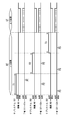
- FIG. 3 is a time chart for explaining the operation of the wireless communication system according to the first embodiment. It is a block diagram of the radio
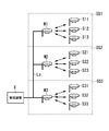
- FIG. It is a block diagram of the main
- FIG. It is explanatory drawing of the frame format of the radio signal in the radio
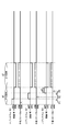
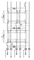
- FIG. 3 is a time chart for explaining operations in the wireless communication system of the first embodiment. It is explanatory drawing of the interference of the radio signal in the radio
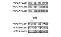
- FIG. It is explanatory drawing of the change method of the slot number in the radio
- FIG. 6 is a time chart for explaining an operation when measuring a reception level of a radio signal in the radio communication system according to the first embodiment.
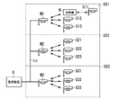
- FIG. 3 is a configuration diagram of a wireless communication system according to a second embodiment.
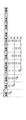
- FIG. It is explanatory drawing of operation
- FIG. It is explanatory drawing of operation
- FIG. It is explanatory drawing of operation
- FIG. It is a block diagram of the modification of the radio
- FIG. It is explanatory drawing of operation
- the wireless communication system to which the technical idea of the present invention can be applied is not limited to the fire alarm system.
- the monitoring device X is connected to the parent devices M1 to M3 and the communication line Ls.
- the wireless communication system includes a plurality (three in the illustrated example) of the parent device Mi and a plurality (9 in the illustrated example) of the slave devices Sij.
- Each of the plurality of parent devices Mi forms a subsystem SSi together with a child device Sij that performs wireless communication with the parent device Mi.
- the plurality of parent devices Mi transmit the first radio signal in the first period (downward section) DT, and wait for the second radio signal in the second period (upstream section) UT after the first period (downstream section) DT.
- the plurality of slave units Sij are configured to transmit the second radio signal in the second period (uplink section) UT when receiving the first radio signal.
- the monitoring device X performs communication (wired communication) with each parent device Mi via the communication line Ls, and is installed in, for example, an apartment room or a management room of a commercial facility. However, in this embodiment, the case where it installs in a housing complex is illustrated.
- the slave unit Sij includes a slave unit control unit 20, an antenna 21, a wireless communication unit 22, a sensor unit 23, a battery power source unit 24, and the like.
- the radio communication unit 22 transmits and receives radio signals using radio waves as a medium in accordance with, for example, “radio station of low power security system” defined in Article 6, Paragraph 4, Item 3 of the Radio Law Enforcement Regulations.
- the radio communication unit 22 is configured to transmit and receive radio signals through a frequency channel selected from a plurality of different frequency channels prepared in advance.
- the frequency channel defined in “Radio equipment of the wireless station of the low power security system standard RCR STD-30” is used.
- 24 frequency channels are defined.
- the band occupied by the frequency channel is 426.2625 to 426.8375 MHz, and the interval between the frequency channels is 25 kHz.
- the frequency channel is not limited to this example.
- the sensor unit 23 is a fire sensor that detects smoke and heat associated with a fire.
- the sensor unit 23 is a security sensor, for example, a human sensor that detects infrared rays radiated from a human body by a pyroelectric element, or a break sensor that detects vibration applied to a window glass.
- the slave unit control unit 20 includes a microcomputer (hereinafter abbreviated as a microcomputer) as a main component, and a speaker (not shown) when a fire is detected by the sensor unit 23 or a fire occurrence notification is received from the master unit Mi.
- the battery power supply unit 24 creates and supplies operation power for the slave unit control unit 20, the wireless communication unit 22, and the sensor unit 23 using a primary battery or a secondary battery as a power source. In order to prevent battery consumption as much as possible, these slave units Sij perform a reception operation intermittently, not always, as will be described later.
- the parent device Mi includes a parent device control unit 10, an antenna 11, a wireless communication unit 12, a sensor unit 13, a wired communication unit 14, a power supply unit 15, and the like.
- the radio communication unit 12 conforms to the “radio station of the low power security system” defined in Article 6, Paragraph 4, Item 3 of the Radio Law Enforcement Regulations, for example, similarly to the radio communication unit 22 of the slave unit Sij. Sends and receives radio signals using radio waves as a medium.
- the radio communication unit 12 is configured to transmit and receive radio signals through a frequency channel selected from a plurality of different frequency channels prepared in advance.
- the radio communication unit 12 also uses a frequency channel defined by “radio equipment of a low-power security system radio station standard RCR STD-30”.
- the wired communication unit 14 performs wired communication with the monitoring device X and another master unit Mj (j ⁇ i) via the communication line Ls.
- the sensor unit 13 is a fire sensor that detects smoke and heat associated with a fire.
- the sensor unit 13 is a security sensor, for example, a human sensor that detects infrared rays radiated from a human body by a pyroelectric element, a break sensor that detects vibration applied to a window glass, or the like. Good.
- the master unit control unit 10 includes a microcomputer as a main component, and detects a fire with the sensor unit 13 or a speaker when a fire occurrence is notified by radio signals from any of the slave units Sij. Processing (such as a buzzer sound or a voice message notifying the occurrence of a fire) is performed from (not shown). Furthermore, the base unit control unit 10 also performs processing based on an instruction received from the monitoring device X via the wired communication unit 14 (such as an inspection start described later) and notification to the monitoring device X.
- the power supply unit 15 converts AC power supplied from an external power supply (for example, commercial AC power supply 100) into DC power and supplies the DC power to the parent device control unit 10, the wireless communication unit 12, the sensor unit 13, and the wired communication unit 14. ing. Note that, since the parent device Mi operates with an external power supply, unlike the child device Sij, the wireless communication unit 12 is always waiting for reception except during transmission.
- an external power supply for example, commercial AC power supply 100
- a unique identification code is assigned to each of the parent device Mi and the child device Sij and stored in the memory of each of the control units 10 and 20, and the transmission destination and the transmission source of wireless communication and wired communication are specified by the identification code. it can.
- the identification code for example, a combination of a system number (identification code of the parent device Mi) i for identifying the subsystem SSi and a child device number j for identifying the child device Sij in the subsystem SSi Is used.
- FIG. 4 shows a frame format 200 of a radio signal transmitted and received by the subsystem SSi in this embodiment. That is, one frame includes a synchronization bit (preamble) 201, a frame synchronization pattern (unique word) 202, a transmission destination address 203, a transmission source address 204, a message (data) 205, and a check code (CRC code, etc.) 206. ing.
- a synchronization bit preamble
- a frame synchronization pattern unique word
- a transmission destination address 203 a transmission destination address 203
- a transmission source address 204 a transmission source address 204
- message data
- CRC code check code
- the radio signal is broadcast (multicast) and all A message is retrieved at the terminal.
- a radio signal including a periodic monitoring message to be described later is broadcast from the parent device Mi to all the child devices Sij. Note that signals of wired communication performed between the parent device Mi of the subsystem SSi and the monitoring device X and the parent device Mi of the subsystem SSi are also common to the frame format 200 shown in FIG.
- each slave unit Sij intermittent reception is performed in order to extend the battery life of the battery power supply unit 24 as much as possible. That is, handset controller 20 repeatedly counts a predetermined intermittent reception cycle (pause period) with a timer built in the microcomputer, and activates wireless communication unit 22 every time the intermittent reception cycle is counted to activate a desired wave ( It is checked whether or not the wireless signal transmitted by the parent device Mi can be received. And if the said radio
- pause period a timer built in the microcomputer
- the radio signal reception check is performed based on a received signal strength indication signal (Receiving Signal Intensity Indication: RSSI signal) output from the wireless communication unit 22 and is a DC voltage signal proportional to the magnitude of the received signal strength.
- RSSI signal Receiveiving Signal Intensity Indication
- mobile_unit control part 20 starts the radio
- the wireless communication unit 22 outputs a received signal strength display signal to the slave unit control unit 20.
- mobile_unit control part 20 determines the presence or absence of a 1st radio signal based on the received signal strength which a received signal strength display signal shows.
- handset controller 20 determines that the first radio signal is present. If handset controller 20 determines that the first radio signal is present, it controls radio communicator 22 to start receiving the first radio signal. Thereby, the handset Sij receives the first radio signal. On the other hand, the slave unit control unit 20 starts the wireless communication unit 22 and the received signal strength does not exceed a predetermined threshold (carrier detection threshold) before the predetermined standby period elapses. It is determined that the first wireless signal does not exist, and the operation of the wireless communication unit 22 is stopped. And the subunit
- a predetermined threshold value carrier detection threshold value
- the base unit control unit 10 of the base unit Mi receives a radio signal (first radio signal; monitoring signal) including a regular monitoring message from the radio communication unit 12 periodically (for example, every several hours to several tens of hours). Report transmission (multicast). That is, base unit Mi is configured to transmit the first radio signal every time a predetermined standby period elapses. In the present embodiment, the parent device Mi repeatedly transmits the first wireless signal during a period (parent device transmission period) Ti.
- the slave unit control unit 20 monitors whether or not the sensor unit 23 has failed or whether or not the battery power source unit 24 has run out of battery at regular intervals (for example, every hour) and the monitoring result. Is stored in a memory (not shown). Then, when receiving the regular monitoring message (first wireless signal) from the parent device Mi, the handset controller 20 receives a wireless signal (first signal) including a notification message for notifying the monitoring result stored in the memory. 2 wireless signal; notification signal) is returned to the main unit Mi. The base unit control unit 10 of the base unit Mi sends back a radio signal including the regular monitoring message (first radio signal) and returns the radio communication unit 12 as a reception state from each slave unit Sij until a predetermined time elapses.
- Second wireless signal Waiting for reception of a wireless signal (second wireless signal). If there is a slave unit Sij that cannot receive a radio signal (second radio signal) including a notification message within a predetermined time or a slave unit Sij that has notified the monitoring result of an abnormality by a notification message, the master unit control unit 10 In addition, the occurrence of an abnormality is notified by sounding a buzzer sound and the signal is transmitted from the wired communication unit 14 to notify the monitoring device X.
- the reason why the base unit Mi cannot receive a radio signal including the notification message (second radio signal) within a predetermined time is that the slave unit Sij and the base unit Mi, in addition to the failure of the slave unit Sij and the battery running out, The communication environment during the period may be degraded (for example, the presence of an obstacle or the occurrence of noise).
- the basic operation (operation when a fire occurs) of the fire alarm system of this embodiment will be described.
- a fire has occurred in a dwelling unit where the subsystem SS3 is installed, and the child device S33 of the subsystem SS3 has detected the fire.
- the child device S33 that detects the fire hereinafter referred to as the fire-source child device S33
- a message (notification message) for the child device control unit 20 to sound an alarm sound from the speaker and notify the occurrence of the fire is issued.
- the wireless signal including the wireless signal is transmitted from the wireless communication unit 22.
- the base unit control unit 10 of the base unit M3 When the base unit M3 receives the radio signal transmitted from the fire-source cordless handset S33, the base unit control unit 10 of the base unit M3 generates an alarm sound from the speaker and wirelessly transmits a radio signal including a notification message. The signal is transmitted from the communication unit 12 and a signal including a notification message is transmitted from the wired communication unit 14.
- the slave unit S31, S32 other than the fire source receives a radio signal (a radio signal including a notification message) transmitted from the fire source slave unit S33 or the master unit M3, the slave unit control unit 20 outputs an alarm sound from the speaker. Ring.
- all the fire alarm devices (master unit M3 and slave units S31 to S33) belonging to the subsystem SS3 can be interlocked to sound an alarm sound in the unit where the fire has occurred (the source unit of the source of fire).
- the monitoring device X that has received the signal transmitted from the master unit M3 of the fire unit dwells sends a notification message to the master units M1 and M2 of the subsystems SS1 and SS2 installed in the dwelling unit other than the fire source.
- the included signal is transmitted via the signal line Ls.
- the occurrence of a fire may be notified from the monitoring device X to a fire department (in the case of a security system, a management center of a company that provides security services) or the like via a network such as the Internet, a public telephone line network, or a mobile phone network. Absent.
- base station control part 10 sounds a warning sound from a speaker, and also transmits the radio signal containing an alert message to a radio
- each subsystem SSi can automatically perform an inspection (operation test) in accordance with an instruction from the monitoring device X.
- a signal (inspection signal) including a message (inspection start message) for notifying the start of inspection from the monitoring device X when the administrator performs a predetermined operation is broadcast to each parent device Mi via the signal line Ls.
- the monitoring device X is configured to transmit an inspection signal to the plurality of parent devices Mi according to a user operation.
- the parent device control unit 10 starts an inspection (operation test).
- this inspection basically the same processing as the periodic monitoring performed for each subsystem SSi is executed. That is, the base unit control unit 10 of the base unit Mi causes the radio communication unit 12 to transmit a radio signal (first radio signal) including an inspection start message.
- the slave unit control unit 20 of each slave unit Sij receives a radio signal (second radio signal) including a notification message for notifying the monitoring result stored in the memory in the same manner as when receiving the regular monitoring message. Reply to Mi.
- the base unit control unit 10 of the base unit Mi sends back a radio signal including an inspection start message (or a regular monitoring message) from each slave unit Sij with the radio communication unit 12 in a reception state until a predetermined time elapses. Wait for reception of a wireless signal. Then, when there is a slave unit Sij that cannot receive a radio signal including a notification message within a predetermined time or a slave unit Sij that has notified the monitoring result with abnormality by a notification message, the master unit control unit 10 sounds a buzzer sound. The occurrence of an abnormality is notified, and a signal is transmitted from the wired communication unit 14 to notify the monitoring device X.
- each parent device Mi transmits a wireless signal (a wireless signal including an inspection start message) in a predetermined order, and all the parent devices Mi have finished transmitting wireless signals.
- Each slave unit Sij returns (transmits) a radio signal including a notification message in a later transmission period (upward section in FIG. 1) UT.
- the wireless communication system includes a plurality of subsystems SSi including a parent device Mi and one or more child devices Sij that perform wireless communication with the parent device Mi.
- the parent devices Mi of the subsystems SSi perform wired communication.
- the plurality of parent devices Mi transmit wireless signals (first wireless signals) in a predetermined order.
- the child device Sij receives the wireless signal (first wireless signal) transmitted from the parent device Mi of the subsystem SSi to which the child device Sij belongs, the child device Sij sends a plurality of wireless signals returned to the parent device Mi (second wireless signal).
- the transmission is performed in the transmission period (upstream section) UT after the master device Mi ends the transmission of the wireless signal (first wireless signal).
- the wireless communication system of this embodiment includes a plurality of subsystems SSi.
- Each of the plurality of subsystems SSi includes one parent device Mi and a child device Sij that performs wireless communication with the parent device Mi.
- Base unit Mi is configured to transmit a first radio signal in a first period (downlink) DT common to a plurality of subsystems SSi.
- Base unit Mi is configured to wait for a second radio signal in a second period (upstream section) UT common to a plurality of subsystems SSi after first period DT.
- mobile_unit Sij is comprised so that a 2nd radio signal may be transmitted in 2nd period UT, if a 1st radio signal is received.
- Base unit Mi is configured to transmit the first radio signal in a period different from base unit Mj of other subsystem SSj within first period DT.
- the plurality of master units Mi sequentially transmit a radio signal (first radio signal) including a regular monitoring message or an inspection start message during the downlink section DT. Then, during the up section UT after the down section DT, the plurality of master units Mi wait for the second radio signal from the slave unit Sij.
- first radio signal including a regular monitoring message or an inspection start message during the downlink section DT.
- the base station M1 of the subsystem SS1 has the first radio in a period T1 that is different from the period T2 of the base station M2 of the other subsystem SS2 and the period T3 of the base station M3 of the other subsystem SS3.
- Base unit M2 transmits the first radio signal in period T2 different from periods T1 and T3.
- Base unit M3 transmits the first radio signal in period T3 different from periods T1 and T2.
- the plurality of parent devices M1, M2, and M3 sequentially transmit the first radio signal.
- the downlink section DT is divided into three periods T1, T2, and T3. Three periods T1, T2, and T3 are assigned to the three parent devices Mi, respectively.
- the order in which the plurality of parent devices Mi transmit the first radio signal is determined in advance. That is, the plurality of parent devices Mi are configured to transmit the first radio signal in a predetermined order. For example, the plurality of parent devices M1, M2, and M3 transmit the first radio signal in this order.
- the first base unit M1 when receiving the inspection signal from the monitoring device X through the communication line Ls, the first base unit M1 transmits a wireless signal (first wireless signal) including an inspection start message.
- the first base unit M1 transmits a radio signal (first radio signal) including a regular monitoring message.
- the base unit M1 After completing the transmission of the first wireless signal, the base unit M1 transmits a start signal to the next base unit M2 through the communication line Ls.
- base unit M2 starts transmitting the first radio signal, and after transmitting the first radio signal, transmits the start signal to the next (last) base unit M3 through communication line Ls.
- the last base unit M3 starts transmitting the first radio signal.
- each parent device Mi stores in advance the transmission order of wireless signals.
- the monitoring device X may be configured to sequentially transmit inspection signals to a plurality of parent devices Mi.
- each parent device Mi is configured to transmit the first radio signal in response to the inspection signal.
- the timing at which each parent device Mi transmits the first wireless signal may be determined such that the plurality of parent devices Mi sequentially transmit the first wireless signal in the downlink section DT.
- radio signals (first radio signals) are not transmitted simultaneously from a plurality of master units Mi, radio signal interference between subsystems SSi of adjacent dwelling units is suppressed. Can do.
- periods (master transmission periods) T1, T2, and T3 in which each master unit Mi transmits a radio signal (first radio signal) including an inspection start message (periodic monitoring message) are fixed.
- mobile_unit S1j in subsystem SS1 is the time which added together the parent
- base station M1. Radio signal transmission (reply) is started after ( T2 + T3) has elapsed.
- the slave unit control unit 20 of the slave unit S2j in the subsystem SS2 wirelessly transmits after the end of the radio signal transmitted from the master unit M2 after the master unit transmission period T3 of the other subsystem SS3 has elapsed. Start signal transmission (reply). However, the slave unit control unit 20 of the slave unit S3j in the subsystem SS3 starts transmitting (replying) the radio signal after the end of the radio signal transmitted from the master unit M3.
- each slave unit Sij transmits a radio signal (second radio signal) including a notification message in a transmission period (upward section) UT after all the base units Mi have finished transmitting radio signals (first radio signals). Can be sent.
- the response reply periods from the slave units Sij of each subsystem SSi are executed simultaneously in parallel.
- each slave unit Sij transmits radio signals using frequency channels that are assigned to each subsystem SSi and are different from each other, thereby suppressing radio signal interference.
- a frequency channel of 426.2625 MHz is assigned to the subsystem SS1
- a frequency channel of 426.2875 MHz is assigned to the subsystem SS2
- a frequency channel of 426.3125 MHz is assigned to the subsystem SS3.
- the slave unit Sij is configured to transmit a radio signal (second radio signal) using a frequency channel assigned to each subsystem SSi.
- a different frequency channel is assigned to each of the plurality of subsystems SSi.
- mobile_unit Sij is comprised so that a 2nd radio signal may be transmitted by the frequency channel allocated to subsystem SSi to which self belongs.
- the master unit Mi is also assigned to each subsystem SSi and transmits radio signals using different frequency channels, so that the radio communication unit 12 has the trouble of changing the frequency channel between transmission and reception. Lost. That is, base unit Mi is configured to transmit a radio signal (first radio signal) using a frequency channel assigned to each subsystem SSi. In other words, the base unit Mi is configured to transmit the first radio signal on the frequency channel assigned to the subsystem SSi to which it belongs.
- the slave unit Sij of each subsystem SSi transmits (replies) a radio signal (a radio signal including a notification message) to the master unit Mi in a time division multiplexing manner. Collisions between radio signals transmitted from the machine Sij are avoided as much as possible.
- the transmission period (upstream section) UT is divided into a plurality of timeslots (the number not less than the number of slave units Sij) (hereinafter, abbreviated as slots), and each sub-system SSi has a master unit Mi.
- One slot is assigned to each sub-system SSi so as not to overlap each child device Sij.
- the base unit Mi is configured to prepare a plurality of time slots in the second period (upward section) UT.
- the parent device Mi is configured to assign a time slot to each of the plurality of child devices Sij included in the subsystem SSi to which the parent device Mi belongs.
- the plurality of subsystems SSi have the same number of time slots synchronized with each other.
- a common slot number is assigned to the synchronized time slots.
- each slave unit Sij is assigned the same slot number as the slave unit number j of the identification code. Therefore, when the transmission period (upstream section) UT of the slave unit Sij is started, the slave unit control unit 20 starts the radio signal in the slot of the assigned slot number in order from the slave unit Si1 whose slave unit number is 1. Since the (second wireless signal) is transmitted to the parent device Mi, it is possible to prevent a wireless signal (second wireless signal) from colliding between the child devices Sij belonging to the same subsystem SSi (see FIG. 1). .
- the reply method from the child device Sij to the parent device Mi is not limited to the time division multiplexing method, and may be another method such as a carrier detection multiple access method.
- the base unit control unit 10 makes the base unit transmission period Ti longer than the intermittent reception cycle so that all the slave units Sij can receive radio signals (first radio signals). There arises a problem that the parent device transmission period Ti until the parent device Mi completes transmission of the wireless signal (first wireless signal) also becomes longer.
- the slave unit control unit 20 of each slave unit Sij periodically broadcasts from the master unit Mi in a situation where no fire is detected (for example, at the start of operation of the system or within one to several hours from the start of operation).
- the timing for starting counting the intermittent reception period (pause period) is adjusted based on the reception timing of the received radio signal (for example, a radio signal including a regular monitoring message).
- the slave unit control unit 20 stops counting the intermittent reception cycle by the timer and terminates the radio signal.
- the count of the intermittent reception cycle by the timer is restarted when a certain waiting time has elapsed from the time.
- the timings at which the counting of the intermittent reception period is completed in each slave unit control unit 20 are aligned. That is, the intermittent reception cycle can be synchronized with respect to all of the plurality of slave units Sij belonging to the same subsystem SSi. If the intermittent reception cycles of all the slave units Sij in the subsystem SSi are synchronized, the timing is that the slave unit Sij receives intermittently (that is, the timing at which the slave unit Sij detects the first radio signal).
- the base unit control unit 10 can transmit a radio signal (first radio signal), and the period during which the base unit Mi transmits a radio signal (first radio signal) (base unit transmission period Ti) can be shortened. it can.
- the slave unit Sij is configured to determine whether or not the first radio signal exists every time a predetermined pause period elapses.
- the handset Sij is configured to start receiving the first wireless signal when it is determined that the first wireless signal is present. Based on the timing at which the child device Sij receives the first radio signal, the child device Sij matches the child device Sij belonging to the same subsystem SSi as the start timing (the timing at which the child device Sij starts the suspension period). Thus, the start timing is configured to be adjusted.
- the start timing of the intermittent reception period (pause period) in each subsystem SSi is intermittent reception in the other subsystem SSj (i ⁇ j). It is necessary to adjust so as not to overlap with the start timing of the cycle (rest period). Therefore, in the present embodiment, the parent devices Mi perform wired communication via the communication line Ls, and the timing for executing the periodic monitoring (timing for transmitting the wireless signal including the periodic monitoring message) is shifted by a predetermined delay time ⁇ T. I am doing so.
- the delay time ⁇ T may be a time ( ⁇ T ⁇ Ti) that is not shorter than the parent device transmission period Ti in each subsystem SSi (see FIG. 5).
- the parent device Mi is configured to communicate with the parent device Mi of another subsystem SSi via the communication line Ls.
- Base unit Mi determines a period (base unit transmission period) Ti for transmitting the first radio signal within first period DT based on information obtained from other subsystems SSi via communication line Ls. Composed.
- the information indicates, for example, an identification code of the parent device Mi that transmits the first radio signal next.
- the parent device Mi transmits an identification code indicating the parent device Mi that transmits the first wireless signal to the other parent device Mi through the communication line Ls.
- the parent device Mi confirms whether or not the received identification code indicates its own identification code.
- Master unit Mi starts transmitting the first radio signal if the received identification code matches its own identification code, and if the received identification code does not match its own identification code, wait.
- the slave unit Sij of the subsystem SSi checks the radio signal radio wave every time a predetermined pause period elapses, and continues to receive the radio signal if the radio wave is captured. If the signal is not captured, intermittent reception is performed to stop the reception of the radio signal and pause, and based on the reception timing of the radio signal periodically broadcast from the master unit Mi of the subsystem SSi, the other subsystems SSi It is preferable to adjust the timing to start the pause period so as not to overlap with the start timing of the pause period.
- each subsystem SSi when the intermittent reception timing of each subsystem SSi is synchronized with a delay time ⁇ T (see FIG. 5) (see FIG. 5), the timing (monitoring) of each parent device Mi instructed to transmit a radio signal It is desirable that an arbitrary master unit Mi first transmits a radio signal according to the timing at which the inspection start message is received from the device X.
- the sum of Ti (that is, the downstream section DT) is fixed.
- an arbitrary parent device Mi among the plurality of parent devices Mi first receives a radio signal (first radio signal). ).
- the parent device Mi when receiving the instruction to transmit the first wireless signal, the parent device Mi is configured to transmit the first wireless signal according to the timing at which the instruction is received.
- the parent device Mi stores the intermittent reception timing (P1, P2, P3) of the subsystem SSi to which it belongs.
- the parent device Mi transmits the time of the next intermittent reception timing to the other parent device Mi through the communication line Ls.
- Base unit Mi compares the time of its next intermittent reception timing with the time of the next intermittent reception timing of another base unit Mi. If the next intermittent reception timing is the earliest, base unit Mi starts transmission of the first radio signal in accordance with the next intermittent reception timing.
- the order in which the plurality of parent devices Mi transmit the first wireless signals is determined according to the parent device Mi that transmits the first wireless signals first.
- the order is base units M1, M2, and M3.
- the order is base units M2, M3, and M1.
- the order is base units M3, M1, and M2. The operation in this case will be described next.
- the intermittent reception timing (see the top ⁇ in FIG. 5) P1 of the subsystem SS1 reaches the intermittent reception timing (see the second ⁇ from the top in FIG. 5) P2 after the passage of P1.
- each parent device Mi has received an inspection start message from the monitoring device X.
- the parent device Mi that first reaches the intermittent reception timing after the time when the inspection start message is received that is, the parent device M2 of the subsystem SS2 first starts transmitting a wireless signal (a wireless signal including the inspection start message). To do.
- the parent device transmission period T2 of the parent device M2 ends, the parent device Mi that reaches the second intermittent reception timing, that is, the parent device M3 of the subsystem SS3 starts transmission of a radio signal. Further, when the parent device transmission period T3 of the parent device M3 ends, the parent device Mi that finally reaches the intermittent reception timing, that is, the parent device M1 of the subsystem SS1 starts to transmit a radio signal.
- the base unit control unit 10 of the base unit M2 that starts transmission of a radio signal first wired a signal including a message to start transmission of the radio signal to the other base units M1 and M3. It is transmitted from the communication unit 14.
- the parent device control unit 10 of the other parent devices M1 and M3 can know the order in which the wireless device starts transmission of the wireless signal by determining the parent device M2 that starts transmission of the wireless signal first. . Then, the parent device control unit 10 of each parent device Mi causes the wireless communication unit 12 to transmit a wireless signal including the order of transmission together with the inspection start message to each child device Sij. Therefore, the child device control unit 20 of each child device Sij determines the start timing of the transmission period (upstream section) for transmitting the radio signal to the parent device Mi based on the transmission order notified from the parent device Mi. can do.
- the parent device Mi may determine the order in which the first wireless signal is transmitted by comparing the time of its next intermittent reception timing with the time of the next intermittent reception timing of another parent device Mi.
- base unit Mi may be configured to determine the time order of its next intermittent reception timing and transmit the first radio signal according to the determined order.
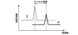
- FIG. 6 shows the electric field strength of the radio signal received by the radio communication unit 12 of the parent device M1, where the solid line ⁇ is the electric field strength of the radio signal transmitted from the child device S11 of the same subsystem SS1, and the broken line ⁇ is the other sub
- the electric field strength of the radio signal transmitted from handset S21 of system SS2 is shown. Since the channel spacing of the frequency channels of these two types of radio signals is relatively narrow, the difference between the electric field strength (power) in the frequency channel of the subsystem SS1 and the adjacent channel leakage power of the frequency channel of the subsystem SS2 becomes small. ing.
- the wireless signal transmitted from the child device S21 of the adjacent subsystem SS2 interferes and the wireless signal of the child device S11 that should be received cannot be received. There is sex.
- the parent device control unit 10 of the parent device M1 transmits the wireless signal again to the child device S11 that has not received the wireless signal.
- the master unit M2 does not transmit a radio signal, and no radio signal is returned from the slave unit S21. Therefore, the wireless signal returned from the child device S11 can be normally received by the wireless communication unit 12 of the parent device M1. If the wireless signal is retransmitted from the base unit M1 in this way, the wireless signal can be received again from the slave unit S11 that could not receive the wireless signal for the first time. Interference is likely to occur.
- the radio signal interference as described above occurs only when the slots (slot numbers) assigned to the two slave units S11 and S21 overlap. Therefore, when the radio signal interference as described above occurs, if the slot assignment to the slave unit S11 of the subsystem SS1 is changed so that the slots of the two slave units S11 and S21 do not overlap, the inspection after the next time Therefore, it is considered that there is a high possibility of avoiding radio signal interference. That is, there is no change in the electric field strength of the interfering radio signal (radio signal transmitted from the slave unit S21), but if the radio signal strength transmitted from the slave unit S1j to be originally received increases, the influence of the interference is exerted. And the radio signal can be received.
- the plurality of child devices Sij belonging to the subsystem SSi are wireless in the time slots assigned by the parent device Mi among the plurality of time slots in which the transmission period (upstream section) UT is divided.
- a time slot for the slave unit Sij Configured to change the assignment.
- each subsystem SSi includes a plurality of child devices Sij.
- Base unit Mi is configured to prepare a plurality of time slots in the second period (upward section) UT.
- the parent device Mi is configured to assign a time slot to each of the plurality of child devices Sij included in the subsystem SSi to which the parent device Mi belongs.
- the slave unit Sij is configured to transmit the second radio signal to the master unit Mi included in the subsystem to which the slave unit Sij belongs using the assigned time slot.
- the parent device Mi is configured to determine whether or not there is a non-response child device with respect to the plurality of child devices Sij included in the subsystem SSi to which the parent device Mi belongs.
- the non-response slave unit is a slave unit Sij in which the master unit Mi cannot receive the second radio signal.
- the base unit Mi is configured to change the time slot of the non-response slave unit to another time slot when it is determined that there is a non-response slave unit.
- the parent device Mi randomly changes the time slot assignment for the child device Sij.
- base unit Mi is configured to randomly select the other time slot from a plurality of time slots.
- the slot numbers are shifted one by one with respect to the slave numbers 1 to N and replaced with slot numbers 2 to N, 1 (change to a slot adjacent to the initial slot). Also good.
- base unit Mi changes the time slot for handset Sij to a time slot adjacent to the time slot.
- the base unit Mi is configured to select a time slot adjacent to the time slot assigned to the non-response handset as the another time slot.
- the slot may be exchanged between the slave unit S13 that could not receive the radio signal and the slave unit S1m that could receive the radio signal.
- the parent device Mi replaces the time slot for the child device Sij with the time slot for the child device Sij that has received the return wireless signal.
- the master device Mi sets the time slot of the non-response slave device to the time assigned to the slave device Sij from which the master device Mi was able to receive the second radio signal. Configured to replace slots.
- the parent device Mi has a time slot for the child device Sij, and a time slot for the child device Sij having the highest reception level of the wireless signal among the child devices Sij that have received the return wireless signal. Is preferably replaced.
- base unit Mi is configured to measure the reception level of the second radio signal.
- the base unit Mi is configured to replace the time slot of the non-response slave unit with the time slot assigned to the slave unit Sij having the highest reception level of the second radio signal when it is determined that the non-response slave unit exists. Is done.
- each slave unit Sij in the subsystem SSi is smaller than the number of slots, and that each slave unit Sij is assigned in order from the first slot (see FIGS. 10 and 11).
- the master unit control unit 10 of the master unit M1 sets the slot of the slave unit S1M to any of the slots. What is necessary is just to change to the empty slot which is not allocated also to subunit
- the number of slave units Sij in the subsystem SSi is less than the number of time slots, and each slave unit Sij is assigned in order from the first time slot.
- the time slot for the child device Sij is changed to a time slot that is not assigned to any child device Sij.
- the plurality of time slots include spare time slots (empty slots) that are not assigned to the child device Sij.
- Base unit Mi is configured to select a spare time slot as another time slot.
- the number of slave units Sij in the subsystem SSi is less than the number of time slots, and each slave unit Sij is assigned in order from the first time slot.
- the time slot for the child device Sij is changed to a time slot that does not overlap with the time slot assigned to the child device Sij of another subsystem.
- the parent device Mi determines whether the no-radiation period during which the child device Sij is not transmitting the second radio signal in any of the other subsystems SSi is in the second period (upward section) UT. Configured to determine. If there is no radio wave period in the second period UT, base unit Mi is configured to select a time slot corresponding to the no radio wave period as another time slot.
- the parent device Mi notifies the other parent device Mi through the communication line Ls of the number of the time slot assigned to the child device Sij.
- Master unit Mi determines that a time slot that is not assigned to any slave unit Sij is a time slot corresponding to a non-radio wave period.
- the reception level (RSSI signal value) of the radio signal transmitted from the child device Sij of the other subsystem SSi is measured in advance by each parent device Mi, When it is necessary to change the allocation, it is preferable to change to a slot that overlaps a slot having a relatively low reception level.
- the parent device Mi measures the reception level of the wireless signal transmitted by the child device Sij of another subsystem in the time slot assigned to the child device Sij, and the reply wireless signal is transmitted.
- the parent device Mi is configured to measure the reception level of the second radio signal from the child device Sij belonging to another subsystem SSi in the second period (upward section) UT.
- Base unit Mi is configured to determine whether or not a low radio wave period in which the reception level is equal to or lower than a predetermined threshold is in the second period (upstream section) UT.
- Base unit Mi is configured to select a time slot corresponding to the low radio wave period as another time slot if there is a low radio wave period in the second period (upward section) UT.
- a signal including a message for notifying the start of the test from the master unit M1 of the subsystem SS1 to the other master units M2 and M3 is transmitted via the signal line Ls.
- a wireless signal is broadcast from the wireless transmission unit 12 of the parent device M1, and the wireless signal is returned (transmitted) by the time division multiplexing method from the child device S1j that has received the wireless signal.
- the wireless communication unit 12 is set in the reception state, the reception level for each slot in the subsystem SS1 is measured, and the parent device control unit 10 measures the measured value (RSSI signal of each slot number). Value) in memory.
- a radio signal is broadcast from the radio transmission unit 12 of the base unit M2, and a radio signal is returned (transmitted) by the time division multiplexing method from the slave unit S2j that has received the radio signal.
- the wireless communication unit 12 is set in the reception state, the reception level for each slot in the subsystem SS2 is measured, and the parent device control unit 10 measures the measurement value (RSSI signal of each slot number). Value) in memory.
- a wireless signal is broadcast from the wireless transmission unit 12 of the parent device M3, and the wireless signal is returned (transmitted) by the time division multiplexing method from the child device S3j that has received the wireless signal.
- the wireless communication unit 12 is set in the reception state, the reception level for each slot in the subsystem SS3 is measured, and the parent device control unit 10 measures the measurement value (RSSI signal of each slot number). Value) in memory.
- the measurement value RSSI signal of each slot number. Value
- the base unit control unit 10 can avoid interference of radio signals by changing to a slot having the lowest reception level or a slot having a reception level equal to or lower than a threshold value. If the measurement values of all slots are stored in the memory of base unit control section 10, when radio signal interference occurs in a plurality of slots, the reception level measurement values should be changed in order from the lowest. Can do.
- the base unit transmission period Ti of each base unit Mi may be fixed or variable as long as the condition that the total time (T1 + T2 + T3) is constant is satisfied.
- the parent device Mi of the subsystem SSi having a relatively low response rate from the previous child device Sij (the number of child devices Sij that have returned) / the total number of child devices Sij) is based on an instruction from the monitoring device X If the next parent device transmission period Ti is extended, the response rate from the child device Sij can be improved.
- the base unit transmission period Ti is changed (extended or shortened) by increasing / decreasing the number of continuous transmissions of radio signals (frames) transmitted from the base unit Mi.
- the parent device Mi of the subsystem SSi does not necessarily need to be based on an instruction from the monitoring device X when changing the parent device transmission period Ti.
- Base unit Mi + 1 may start transmission of a radio signal (base unit transmission period Ti + 1).
- the total time of the parent device transmission period Ti can be extended within the range of the transmission time defined in the Radio Law. If the response rate from the child device Sij is improved as described above, the child device Sij cannot be received due to the noise generated during the parent device transmission period Ti because the parent device transmission period Ti is short. Can be improved by lengthening the parent device transmission period Ti.
- Embodiment 2 This embodiment belongs to the subsystem SSi as shown in FIG. 13, and relays a radio signal transmitted from the parent device Mi of the subsystem SSi to at least a part of the child devices Sij of the subsystem SSi. It is characterized by having R.
- the relay device R relays the radio signal between the parent device M1 and the child device S11 of the subsystem SS1.
- the relay machine R has almost the same configuration as the parent machine Mi, except that it does not have a sensor unit and a wired communication unit, and is supplied with power from the commercial AC power supply 100.
- the identification code of the relay device R may be a combination of a system number and a slave device number as in the slave device Sij, or a combination of a relay device number and a system number different from the slave device number. Also good.
- the relay station R when a radio signal including a notification message is transmitted from the slave unit S11, the relay station R that has received the radio signal transmits a radio signal including the notification message to the master unit M1, thereby A radio signal from the machine S11 to the master machine M1 is relayed by the relay machine R.
- a radio signal (a radio signal including a notification message or a periodic monitoring message) is transmitted from the parent device M1
- the relay device R that has received the radio signal includes a notification message addressed to the child device S11.
- the radio signal from the parent device M1 to the child device S11 is relayed by the relay device R.
- the relay device R transmits (relays) a radio signal after all the master devices M1 to M3 have finished transmitting the radio signal.
- the parent device transmission period changes according to the timing ( ⁇ mark in the drawing) of receiving the inspection start message from the monitoring device X. That is, as shown in the uppermost part of FIG. 16, when the base unit M2 transmits a radio signal for the first time, after the base unit M3 transmits after the base unit M2, the transmission period T of the relay unit R has passed.
- the relay unit R transmits after the transmission period T of the base units M2 and M3 that have been transmitted by the base unit M1 and have already been transmitted.
- the parent device transmission period TM is a time in the range of 7 ⁇ T ⁇ TM ⁇ 8 ⁇ T.
- the relay unit R transmits after the base units M2 and M3 transmit after the base unit M1.
- the transmission period TM is a time in the range of 4 ⁇ T ⁇ TM ⁇ 5 ⁇ T.
- the base unit transmission period TM is a time in the range of 5 ⁇ T ⁇ TM ⁇ 6 ⁇ T or 6 ⁇ T ⁇ TM ⁇ 7 ⁇ T (see FIG. 16).
- the relay device R transmits (relays) a radio signal after the master devices M1 and M2 have finished transmitting the radio signal.
- the base unit M2 transmits a radio signal for the first time
- the base unit M3 passes after the transmission period T of the relay unit R passes.
- the relay station R transmits after the transmission period T of the base unit M2 that has already been transmitted and M1 has been transmitted. Therefore, the parent device transmission period TM is a time in the range of 6 ⁇ T ⁇ TM ⁇ 7 ⁇ T.
- the parent device transmission period TM is a time in the range of 6 ⁇ T ⁇ TM ⁇ 7 ⁇ T.
- the base unit transmission period TM is a time in the range of 4 ⁇ T ⁇ TM ⁇ 5 ⁇ T.
- the base unit transmission period TM is a time in the range of 4 ⁇ T ⁇ TM ⁇ 5 ⁇ T or 5 ⁇ T ⁇ TM ⁇ 6 ⁇ T (see FIG. 15).
- the relay device R transmits (relays) a wireless signal before the next parent device M2 transmits after the relay source parent device M1 finishes transmitting the wireless signal.
- the first parent device M2 after the transmission period T of the relay device R has passed.
- the repeater R transmits. Therefore, the base unit transmission period TM is a time in the range of 5 ⁇ T ⁇ TM ⁇ 6 ⁇ T.
- the base unit transmission periods TM are all in the range of 4 ⁇ T ⁇ TM ⁇ 5 ⁇ T. Time is reached (see FIG. 14).
- the subsystem SSi transmits a wireless signal (first wireless signal) transmitted from the parent device Mi of the subsystem SSi to at least one of the child devices Sij of the subsystem SSi.
- the relay device R has a relay device R which relays the master device Mi of the other subsystem SSi after the master device Mi, which is the relay source, has finished transmitting the wireless signal (first wireless signal). It is preferable to relay the radio signal (first radio signal) before starting transmission of the radio signal (first radio signal).
- the subsystem SSi has a repeater R that relays the first radio signal from the parent device Mi to the child device Sij.
- the repeater R is configured to transmit the first wireless signal to the child device Sij during the interval of the first wireless signal when receiving the first wireless signal from the parent device Mi of the subsystem SSi to which the repeater R belongs.
- the interval period is a period from when the parent device Mi of the subsystem SSi to which the repeater R belongs has finished transmitting the first wireless signal until the next parent device Mi starts transmitting the first wireless signal.
- the relay is performed before the next master unit M2 transmits.
- the transmission time of the parent device can be shortened.
- the radio signal relayed by the relay R1 can be relayed by another relay R2.
- the relay device R2 when a wireless signal including a notification message is transmitted from the slave unit S11, the relay device R2 that has received the wireless signal transmits (relays) a wireless signal including the notification message to the relay device R1, Further, the relay device R1 that has received the wireless signal transmits a wireless signal including a notification message to the parent device M1.
- a radio signal (a radio signal including a notification message or a periodic monitoring message) is transmitted from the base unit M1
- the relay device R1 that has received the radio signal is addressed to the relay device R2 and includes a notification message.
- the relay device R2 When the relay device R2 that has transmitted the signal and further receives the wireless signal transmits a wireless signal including a notification message to the child device S11, two wireless signals are transmitted from the parent device M1 to the child device S11. It is relayed by relay machines R1 and R2.
- relay devices R1 and R2 Even when wireless signals are relayed through a plurality of relay devices R1 and R2 in this way, as shown in FIG. 19, the relay devices R1 and R3 after all the master devices M1 to M3 have finished transmitting wireless signals.
- R2 relays a radio signal, as shown in FIG. 18, after relay machine M1 completes the transmission of the radio signal, relays R1 and R2 receive the radio signal before the next master machine M2 transmits. It is possible to shorten the transmission period of the master unit by relaying.
Landscapes
- Engineering & Computer Science (AREA)
- Computer Networks & Wireless Communication (AREA)
- Signal Processing (AREA)
- Business, Economics & Management (AREA)
- Emergency Management (AREA)
- Physics & Mathematics (AREA)
- General Physics & Mathematics (AREA)
- Mobile Radio Communication Systems (AREA)
- Alarm Systems (AREA)
- Time-Division Multiplex Systems (AREA)
Abstract
Description
した子機からの返信を受信することにより、各子機の電池寿命や故障の有無を監視している。
本実施形態の火災警報システム(無線通信システム)は、図2に示すように複数(図示例では3つ)のサブシステムSS1~SS3と、各サブシステムSSi(i=1,2,3)の親機M1~M3と通信線Lsを介して接続された監視装置Xとで構成されている。
見込みがある。
本実施形態は、図13に示すようにサブシステムSSiに属し、当該サブシステムSSiの親機Miから送信される無線信号を、当該サブシステムSSiの子機Sijの少なくとも一部に中継する中継機Rを有する点に特徴がある。図示例では、サブシステムSS1の親機M1と子機S11の間で中継機Rが無線信号を中継している。
Claims (15)
- 複数のサブシステムを備え、
前記複数のサブシステムのそれぞれは、1つの親機と、前記親機と無線通信を行う子機とを含み、
前記親機は、前記複数のサブシステムに共通する第1期間内に第1無線信号を送信し、前記第1期間後の前記複数のサブシステムに共通する第2期間に第2無線信号を待ち受けるように構成され、
前記子機は、前記第1無線信号を受信すると、前記第2期間に前記第2無線信号を送信するように構成され、
前記親機は、前記第1期間内で、他のサブシステムの前記親機と異なる期間に前記第1無線信号を送信するように構成される
ことを特徴とする無線通信システム。 - 前記複数のサブシステムのそれぞれには異なる周波数チャネルが割り当てられ、
前記子機は、自身が属するサブシステムに割り当てられた前記周波数チャネルで前記第2無線信号を送信するように構成される
ことを特徴とする請求項1記載の無線通信システム。 - 前記親機は、自身が属するサブシステムに割り当てられた前記周波数チャネルで前記第1無線信号を送信するように構成される
ことを特徴とする請求項2記載の無線通信システム。 - 前記子機は、所定の休止期間が経過する毎に、前記第1無線信号の有無を判定するように構成され、
前記子機は、前記第1無線信号が存在していると判定すると前記第1無線信号の受信を開始するように構成され、
前記子機は、前記子機が前記第1無線信号を受信したタイミングに基づいて、前記子機が前記休止期間を開始するタイミングである開始タイミングが自身と同じサブシステムに属する前記子機と一致するように、前記開始タイミングを調整するように構成される
ことを特徴とする請求項1~3の何れか1項に記載の無線通信システム。 - 前記親機は、通信線を介して他のサブシステムの前記親機と通信するように構成され、
前記親機は、前記第1期間内で前記第1無線信号を送信する期間を、前記通信線を介して他のサブシステムから得た情報に基づいて決定するように構成される
ことを特徴とする請求項4記載の無線通信システム。 - 前記親機は、前記第1無線信号の送信の指示を受け取ると、前記指示を受け取ったタイミングに応じて前記第1無線信号の送信を行うように構成される
ことを特徴とする請求項1~3のうちいずれか1項記載の無線通信システム。 - 前記各サブシステムは、複数の前記子機を含み、
前記親機は、前記第2期間において、複数のタイムスロットを用意するように構成され、
前記親機は、自身が属するサブシステムに含まれる前記複数の子機のそれぞれに前記タイムスロットを割り当てるように構成され、
前記子機は、割り当てられたタイムスロットを用いて前記第2無線信号を自身が属するサブシステムに含まれる前記親機に送信するように構成され、
前記親機は、自身が属するサブシステムに含まれる前記複数の子機に関して、無応答子機が存在するか否かを判定するように構成され、
前記無応答子機は、前記親機が前記第2無線信号を受信できなかった前記子機であり、
前記親機は、前記無応答子機が存在すると判定した場合に、前記無応答子機の前記タイムスロットを別のタイムスロットに変更するように構成される
ことを特徴とする請求項1~3のうちいずれか1項記載の無線通信システム。 - 前記親機は、前記別のタイムスロットを前記複数のタイムスロットからランダムに選択するように構成される
ことを特徴とする請求項7記載の無線通信システム。 - 前記親機は、前記無応答子機に割り当てられた前記タイムスロットに隣接するタイムスロットを前記別のタイムスロットとして選択するように構成される
ことを特徴とする請求項7記載の無線通信システム。 - 前記親機は、前記無応答子機が存在すると判定した場合に、前記無応答子機の前記タイムスロットを、前記親機が前記第2無線信号を受信した前記子機に割り当てられた前記タイムスロットと入れ替えるように構成される
ことを特徴とする請求項7記載の無線通信システム。 - 前記親機は、前記第2無線信号の受信レベルを測定するように構成され、
前記親機は、前記無応答子機が存在すると判定した場合に、前記無応答子機の前記タイムスロットを、前記第2無線信号の前記受信レベルが最も高い前記子機に割り当てられた前記タイムスロットと入れ替えるように構成される
ことを特徴とする請求項10記載の無線通信システム。 - 前記複数のタイムスロットは、前記子機に割り当てられていない予備のタイムスロットを含み、
前記親機は、前記予備のタイムスロットを前記別のタイムスロットとして選択するように構成される
ことを特徴とする請求項7記載の無線通信システム。 - 前記親機は、他のいずれの前記サブシステムにおいても前記子機が前記第2無線信号を送信していない無電波期間が前記第2期間にあるか否かを判定するように構成され、
前記親機は、前記第2期間に前記無電波期間があれば、前記無電波期間に対応する前記タイムスロットを、前記別のタイムスロットとして選択するように構成される
ことを特徴とする請求項7記載の無線通信システム。 - 前記親機は、前記第2期間において他の前記サブシステムに属する前記子機からの前記第2無線信号の受信レベルを測定するように構成され、
前記親機は、前記受信レベルが所定の閾値以下となる低電波期間が前記第2期間にあるか否かを判定するように構成され、
前記親機は、前記第2期間に前記低電波期間があれば、前記低電波期間に対応する前記タイムスロットを、前記別のタイムスロットとして選択するように構成される
ことを特徴とする請求項7記載の無線通信システム。 - 前記サブシステムは、前記親機からの前記第1無線信号を前記子機に中継する中継器を有し、
前記中継器は、自身が属するサブシステムの前記親機から前記第1無線信号を受信すると、前記第1無線信号のインターバル期間に、前記第1無線信号を前記子機に送信するように構成され、
前記インターバル期間は、前記中継器が属する前記サブシステムの前記親機が前記第1無線信号の送信を終了してから次の前記親機が前記第1無線信号の送信を開始するまでの期間である
ことを特徴とする請求項1~3のうちいずれか1項記載の無線通信システム。
Priority Applications (2)
| Application Number | Priority Date | Filing Date | Title |
|---|---|---|---|
| JP2012555934A JPWO2012105614A1 (ja) | 2011-02-02 | 2012-02-01 | 無線通信システム |
| EP12741706.1A EP2672774B1 (en) | 2011-02-02 | 2012-02-01 | Wireless communication system |
Applications Claiming Priority (2)
| Application Number | Priority Date | Filing Date | Title |
|---|---|---|---|
| JP2011020790 | 2011-02-02 | ||
| JP2011-020790 | 2011-02-02 |
Publications (1)
| Publication Number | Publication Date |
|---|---|
| WO2012105614A1 true WO2012105614A1 (ja) | 2012-08-09 |
Family
ID=46602820
Family Applications (1)
| Application Number | Title | Priority Date | Filing Date |
|---|---|---|---|
| PCT/JP2012/052297 Ceased WO2012105614A1 (ja) | 2011-02-02 | 2012-02-01 | 無線通信システム |
Country Status (4)
| Country | Link |
|---|---|
| EP (1) | EP2672774B1 (ja) |
| JP (1) | JPWO2012105614A1 (ja) |
| TW (1) | TW201240391A (ja) |
| WO (1) | WO2012105614A1 (ja) |
Cited By (6)
| Publication number | Priority date | Publication date | Assignee | Title |
|---|---|---|---|---|
| JP2014064097A (ja) * | 2012-09-20 | 2014-04-10 | Mitsubishi Electric Corp | モデムシステム |
| JP2014200004A (ja) * | 2013-03-29 | 2014-10-23 | パナソニック株式会社 | 負荷制御システム |
| JP2015154138A (ja) * | 2014-02-12 | 2015-08-24 | Kddi株式会社 | チャネル選択装置、チャネル選択システム及びチャネル選択方法 |
| JPWO2016093256A1 (ja) * | 2014-12-11 | 2017-07-13 | 株式会社テイエルブイ | 対象情報管理システム、通信中継装置、及び、通信中継プログラム |
| WO2020110562A1 (ja) * | 2018-11-30 | 2020-06-04 | パナソニックIpマネジメント株式会社 | 検知器、検知システム、検知器管理システム、制御方法、及びプログラム |
| JP2020107931A (ja) * | 2018-12-26 | 2020-07-09 | 沖電気工業株式会社 | 基地局、無線通信プログラム、及び無線通信方法 |
Families Citing this family (4)
| Publication number | Priority date | Publication date | Assignee | Title |
|---|---|---|---|---|
| US10574410B2 (en) | 2014-11-24 | 2020-02-25 | Telefonaktiebolaget Lm Ericsson (Publ) | Transmission and reception in a determined third set of time-frequency resources |
| EP3225004A4 (en) | 2014-11-24 | 2018-06-20 | Telefonaktiebolaget LM Ericsson (publ) | Using a precoded multi-carrier modulation scheme in a wireless communication network |
| JP7065313B2 (ja) * | 2018-01-15 | 2022-05-12 | パナソニックIpマネジメント株式会社 | 検知情報通信装置、検知情報通信システム、通信システム、無線通信方法およびプログラム |
| CN111179534B (zh) * | 2020-01-06 | 2022-03-22 | 广东工业大学 | 一种森林火灾撤离方法及传感器 |
Citations (4)
| Publication number | Priority date | Publication date | Assignee | Title |
|---|---|---|---|---|
| JPH0923280A (ja) * | 1995-07-05 | 1997-01-21 | Tokyo Gas Co Ltd | 無線通信システム |
| JP2004127176A (ja) * | 2002-10-07 | 2004-04-22 | Matsushita Electric Ind Co Ltd | 無線データ収集システム |
| JP2009065337A (ja) * | 2007-09-05 | 2009-03-26 | Sharp Corp | 無線テレメータシステム |
| JP2010226569A (ja) * | 2009-03-25 | 2010-10-07 | Panasonic Corp | 検針用無線中継器 |
Family Cites Families (5)
| Publication number | Priority date | Publication date | Assignee | Title |
|---|---|---|---|---|
| US7433697B2 (en) * | 2003-10-24 | 2008-10-07 | Broadcom Corporation | Synchronized UWB piconets for Simultaneously Operating Piconet performance |
| JP4396584B2 (ja) * | 2005-06-08 | 2010-01-13 | パナソニック電工株式会社 | 火災報知システム |
| WO2008088079A1 (en) * | 2007-01-17 | 2008-07-24 | Panasonic Electric Works Co., Ltd. | Wireless fire alarm system |
| JP2009159326A (ja) * | 2007-12-26 | 2009-07-16 | Kyocera Corp | 移動通信共存システム、基地局装置、および基地局装置の制御方法 |
| JP5559791B2 (ja) * | 2008-08-11 | 2014-07-23 | コーニンクレッカ フィリップス エヌ ヴェ | 身体領域ネットワーク用の媒体アクセス制御(mac)プロトコル |
-
2012
- 2012-02-01 JP JP2012555934A patent/JPWO2012105614A1/ja active Pending
- 2012-02-01 WO PCT/JP2012/052297 patent/WO2012105614A1/ja not_active Ceased
- 2012-02-01 TW TW101103260A patent/TW201240391A/zh unknown
- 2012-02-01 EP EP12741706.1A patent/EP2672774B1/en not_active Not-in-force
Patent Citations (4)
| Publication number | Priority date | Publication date | Assignee | Title |
|---|---|---|---|---|
| JPH0923280A (ja) * | 1995-07-05 | 1997-01-21 | Tokyo Gas Co Ltd | 無線通信システム |
| JP2004127176A (ja) * | 2002-10-07 | 2004-04-22 | Matsushita Electric Ind Co Ltd | 無線データ収集システム |
| JP2009065337A (ja) * | 2007-09-05 | 2009-03-26 | Sharp Corp | 無線テレメータシステム |
| JP2010226569A (ja) * | 2009-03-25 | 2010-10-07 | Panasonic Corp | 検針用無線中継器 |
Non-Patent Citations (1)
| Title |
|---|
| See also references of EP2672774A4 * |
Cited By (9)
| Publication number | Priority date | Publication date | Assignee | Title |
|---|---|---|---|---|
| JP2014064097A (ja) * | 2012-09-20 | 2014-04-10 | Mitsubishi Electric Corp | モデムシステム |
| JP2014200004A (ja) * | 2013-03-29 | 2014-10-23 | パナソニック株式会社 | 負荷制御システム |
| JP2015154138A (ja) * | 2014-02-12 | 2015-08-24 | Kddi株式会社 | チャネル選択装置、チャネル選択システム及びチャネル選択方法 |
| JPWO2016093256A1 (ja) * | 2014-12-11 | 2017-07-13 | 株式会社テイエルブイ | 対象情報管理システム、通信中継装置、及び、通信中継プログラム |
| WO2020110562A1 (ja) * | 2018-11-30 | 2020-06-04 | パナソニックIpマネジメント株式会社 | 検知器、検知システム、検知器管理システム、制御方法、及びプログラム |
| JP2020087361A (ja) * | 2018-11-30 | 2020-06-04 | パナソニックIpマネジメント株式会社 | 検知器、検知システム、検知器管理システム、制御方法、及びプログラム |
| JP7241313B2 (ja) | 2018-11-30 | 2023-03-17 | パナソニックIpマネジメント株式会社 | 検知器、検知システム、検知器管理システム、制御方法、及びプログラム |
| JP2020107931A (ja) * | 2018-12-26 | 2020-07-09 | 沖電気工業株式会社 | 基地局、無線通信プログラム、及び無線通信方法 |
| JP7168933B2 (ja) | 2018-12-26 | 2022-11-10 | 沖電気工業株式会社 | 基地局、無線通信プログラム、及び無線通信方法 |
Also Published As
| Publication number | Publication date |
|---|---|
| JPWO2012105614A1 (ja) | 2014-07-03 |
| EP2672774A1 (en) | 2013-12-11 |
| EP2672774B1 (en) | 2017-04-26 |
| TW201240391A (en) | 2012-10-01 |
| EP2672774A4 (en) | 2015-03-04 |
Similar Documents
| Publication | Publication Date | Title |
|---|---|---|
| JP5838350B2 (ja) | 無線機及び無線通信システム | |
| WO2012105614A1 (ja) | 無線通信システム | |
| CN104348605A (zh) | 关键应用中使用的用于无线网络的抗干扰技术 | |
| JP4475341B2 (ja) | 火災警報システム | |
| US9730091B2 (en) | Method and system improving the reliability of wireless fire detection systems | |
| JP2009230406A5 (ja) | ||
| JP5193143B2 (ja) | 火災警報システム | |
| JP2009265763A (ja) | 火災警報システム | |
| JP5507979B2 (ja) | 無線通信システム | |
| JP2011176481A (ja) | 無線通信システム | |
| JP4835285B2 (ja) | 火災報知システム | |
| JP4501786B2 (ja) | 火災報知システム | |
| JP2013176034A (ja) | 無線通信システム | |
| JP6481918B2 (ja) | 無線通信システム | |
| JP5091956B2 (ja) | 火災警報システム | |
| EP3273628A1 (en) | Communication system and communication device | |
| JP5942147B2 (ja) | 無線通信システム | |
| JP2014204423A (ja) | 無線通信システム | |
| JP6273544B2 (ja) | 無線通信システム | |
| JP5492022B2 (ja) | 無線通信システム | |
| WO2010050492A1 (ja) | 火災警報システム及び火災警報装置 | |
| JP2013175154A (ja) | 無線通信システム | |
| JP6004306B2 (ja) | 火災警報器及び火災警報システム | |
| JP2008026982A (ja) | 火災報知システム | |
| JP5945850B2 (ja) | 無線通信システム |
Legal Events
| Date | Code | Title | Description |
|---|---|---|---|
| 121 | Ep: the epo has been informed by wipo that ep was designated in this application |
Ref document number: 12741706 Country of ref document: EP Kind code of ref document: A1 |
|
| ENP | Entry into the national phase |
Ref document number: 2012555934 Country of ref document: JP Kind code of ref document: A |
|
| NENP | Non-entry into the national phase |
Ref country code: DE |
|
| REEP | Request for entry into the european phase |
Ref document number: 2012741706 Country of ref document: EP |
|
| WWE | Wipo information: entry into national phase |
Ref document number: 2012741706 Country of ref document: EP |