WO2012108088A1 - 相違領域検出システム及び相違領域検出方法 - Google Patents
相違領域検出システム及び相違領域検出方法 Download PDFInfo
- Publication number
- WO2012108088A1 WO2012108088A1 PCT/JP2011/077376 JP2011077376W WO2012108088A1 WO 2012108088 A1 WO2012108088 A1 WO 2012108088A1 JP 2011077376 W JP2011077376 W JP 2011077376W WO 2012108088 A1 WO2012108088 A1 WO 2012108088A1
- Authority
- WO
- WIPO (PCT)
- Prior art keywords
- difference
- area
- image
- detection system
- different area
- Prior art date
- Legal status (The legal status is an assumption and is not a legal conclusion. Google has not performed a legal analysis and makes no representation as to the accuracy of the status listed.)
- Ceased
Links
Images





Classifications
-
- G—PHYSICS
- G06—COMPUTING OR CALCULATING; COUNTING
- G06V—IMAGE OR VIDEO RECOGNITION OR UNDERSTANDING
- G06V20/00—Scenes; Scene-specific elements
- G06V20/40—Scenes; Scene-specific elements in video content
- G06V20/46—Extracting features or characteristics from the video content, e.g. video fingerprints, representative shots or key frames
- G06V20/47—Detecting features for summarising video content
-
- G—PHYSICS
- G06—COMPUTING OR CALCULATING; COUNTING
- G06T—IMAGE DATA PROCESSING OR GENERATION, IN GENERAL
- G06T7/00—Image analysis
- G06T7/20—Analysis of motion
- G06T7/246—Analysis of motion using feature-based methods, e.g. the tracking of corners or segments
-
- G—PHYSICS
- G06—COMPUTING OR CALCULATING; COUNTING
- G06V—IMAGE OR VIDEO RECOGNITION OR UNDERSTANDING
- G06V10/00—Arrangements for image or video recognition or understanding
- G06V10/40—Extraction of image or video features
- G06V10/44—Local feature extraction by analysis of parts of the pattern, e.g. by detecting edges, contours, loops, corners, strokes or intersections; Connectivity analysis, e.g. of connected components
-
- G—PHYSICS
- G06—COMPUTING OR CALCULATING; COUNTING
- G06V—IMAGE OR VIDEO RECOGNITION OR UNDERSTANDING
- G06V20/00—Scenes; Scene-specific elements
- G06V20/60—Type of objects
- G06V20/62—Text, e.g. of license plates, overlay texts or captions on TV images
- G06V20/635—Overlay text, e.g. embedded captions in a TV programme
-
- G—PHYSICS
- G06—COMPUTING OR CALCULATING; COUNTING
- G06T—IMAGE DATA PROCESSING OR GENERATION, IN GENERAL
- G06T2207/00—Indexing scheme for image analysis or image enhancement
- G06T2207/10—Image acquisition modality
- G06T2207/10016—Video; Image sequence
Definitions
- the present invention relates to a different area detection system and a different area detection method.
- illegal videos generated from original videos have been flooded, which has become a social problem.
- Examples of illegal moving images include those obtained by copying the original video as it is, those obtained by extracting a part of the video such as a highlight scene, and those modified from the original video by adding a telop or the like. Therefore, it is required to detect a video that is identical to the original video in consideration of the video modified in this way.
- Patent Document 1 discloses a technique for determining the identity of two images. Specifically, in the technique disclosed in the cited document 1, the image identity is determined by generating a multi-dimensional feature vector for each image and comparing the feature vectors between the images. By applying such a technique to, for example, a part of frame images in a video, it is possible to determine the identity between videos even when the video is modified.
- the technique disclosed in Patent Document 1 can determine the identity between videos, but the presence or absence of a telop, the difference in the contents of a telop, etc. between videos determined to be the same, etc.
- the present invention has been made in view of such circumstances, and an object thereof is to detect a local difference area between images.
- a different area detection system includes a first feature quantity vector that is a set of feature quantities corresponding to each of a plurality of partial areas in a first image, and a plurality of pieces in a second image. Generate inter-image difference information indicating the difference between the first and second images for each partial area based on the second feature quantity vector that is a set of feature quantities corresponding to each of the partial areas. Based on the difference in each partial area indicated by the difference information generation unit and the inter-image difference information, a different area that is an image area that is different between the first and second images is detected, and the detection result is shown. A different area detection unit that outputs detection information.
- the “unit” does not simply mean a physical means, but includes a case where the function of the “unit” is realized by software. Also, even if the functions of one “unit” or device are realized by two or more physical means or devices, the functions of two or more “units” or devices are realized by one physical means or device. May be.
- a local difference area between images can be detected.
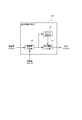
- FIG. 1 It is a figure which shows the structure of the different area
- FIG. 1 is a diagram showing a configuration of a different area detection system according to an embodiment of the present invention.
- the different area detection system 10 is a system that detects an area having a local difference between identical videos, and includes a feature amount extraction unit 20, a feature amount storage unit 21, a difference information generation unit 22, and a difference information storage unit. 23, a different area detection unit 24, a detection information storage unit 25, and a detection result output unit 26.
- the local difference is also referred to as “local modification”.
- the different area detection system 10 refers to a feature amount database (DB) 30 and a video database (DB) 32.
- DB feature amount database
- DB video database
- the different area detection system 10 is configured by using one or a plurality of information processing apparatuses, and the feature amount extraction unit 20, the difference information generation unit 22, the different area detection unit 24, and the detection result output unit 26 include: This can be realized by the processor executing the program stored in the memory.
- the feature amount storage unit 21 and the difference information storage unit 23 can be realized using a storage area such as a memory or a storage device.
- FIG. 2 is a diagram illustrating an example of a different area detected by the different area detection system 10.
- a different area is an area where local alteration has occurred.
- FIG. 2 shows identical images 40 and 42.
- the video 40 is, for example, a commercial CM video of a car that is newly sold, and a subtitle “March 1 debut!” Is displayed in the lower image area 44 of the frame image constituting the video 40. Yes.
- the video 42 is a CM video of the same car, but is a CM video that is broadcast after sales of the car are started. Therefore, the subtitle displayed in the image area 46 below the frame image constituting the video 42 is “On sale now!”.
- the different area detection system 10 can detect the different area 48 between the images 40 and 42. Similarly, the different area detection system 10 can detect, for example, a different area that is an area in which an illegal video generated from an original video is altered from the original video.
- the feature quantity extraction unit 20 extracts a feature quantity vector from each of a plurality of frame images constituting the input video, and stores the feature quantity vector in the feature quantity storage unit 21.
- the input video is, for example, a video being broadcast or a video uploaded to a video site.
- the feature amount vector is a set of N feature amounts corresponding to N (N ⁇ 2) partial regions defined in the frame image. For example, a method described in International Publication No. 2010/0884714 Can be generated.
- Each partial area corresponding to each dimension of the feature quantity vector includes, for example, a plurality of partial areas in the frame image.
- the feature-value of each dimension can be produced
- FIG. 3 is a diagram showing an example of area division of a frame image. As shown in FIG. 3, for example, each frame image can be divided into 32 ⁇ 32 1024 areas (divided areas). The partial area corresponding to each dimension in the feature vector is constituted by a combination of one or more divided areas.
- FIG. 4 is a diagram showing an image when extracting feature values in the Mth dimension.
- the partial areas corresponding to the Mth dimension are two partial areas 62 and 64.
- the feature quantity extraction unit 20 may generate an M-th dimension feature quantity based on the difference between the feature quantity (area feature quantity) of the partial area 62 and the feature quantity (area feature quantity) of the partial area 64. it can.
- the feature amount of each of the partial areas 62 and 64 can be calculated using an arbitrary method such as an average value or a median value of pixel values in each partial area.
- the feature quantity extraction unit 20 can generate the Mth dimension feature quantity by quantizing the difference between the area feature quantities of the partial areas 62 and 64 into, for example, three values ( ⁇ 1, 0, 1). .
- the feature quantity extraction unit 20 can generate an N-dimensional feature quantity vector by generating feature quantities for each dimension (first dimension to Nth dimension). Note that the feature value calculation method for each dimension described here is merely an example, and any method may be used as long as it is generated based on the feature value of the partial region set for each dimension.
- FIG. 5 is a diagram showing an example of a feature quantity vector stored in the feature quantity storage unit 21.
- the feature vector is stored in association with a video identifier for identifying an input video and sequence information indicating the temporal order of frame images.
- the video identifier is for identifying a group of videos. For example, a video title, a program name, a file name, a URL (Uniform Resource Locator), or the like can be used.
- the sequence information may be information that can grasp the order of the feature vector, and for example, a frame number or the like can be used. Note that there is no need for a video identifier if there is only one video input. Further, the sequence information may be omitted as long as the temporal order of the feature vector can be identified by the data storage structure or the like.
- the difference information generation unit 22 compares the feature amount vector of the input video stored in the feature amount storage unit 21 with the feature amount vector stored in the feature amount DB 30, and is identical. A difference vector is generated from a feature vector between videos. Note that the difference information generation unit 22 can also generate a difference vector by comparing feature quantity vectors stored in the feature quantity DB 30. That is, the different area detection system 10 can also detect a different area between a plurality of videos in which feature quantity vectors are stored in the feature quantity DB 30.
- FIG. 6 is a diagram illustrating an example of a feature amount vector stored in the feature amount DB 30.
- the feature quantity DB 30 stores feature quantity vectors for a plurality of videos to be compared with the input video.
- a video in which a feature vector is stored in the feature DB 30 is referred to as an original video.
- the feature vector of the original video is stored in association with the video identifier for identifying the original video, the creation date and time of the original video, and the sequence information indicating the temporal order of the frame images.
- FIG. 7 is a diagram illustrating a configuration example of the difference information generation unit 22.
- the difference information generation unit 22 can be configured to include a feature amount comparison unit 70, a frame selection unit 72, and a difference information output unit 74.
- the feature amount comparison unit 70 compares the feature amount vector of the input video and the feature amount vector of the feature amount DB 30 for each frame, for example.
- the frame selection unit 72 selects a frame image that is determined to be identical between the input video and the original video based on the comparison result in the feature amount comparison unit 70. For determining the identity between frame images, for example, the number of dimensions in which feature quantities match between two feature quantity vectors, the number of dimensions in which feature quantities do not match, and the size of feature quantity vectors are compared. Can be done.
- the difference information output unit 74 outputs difference area information indicating a dimension in which the feature amount difference is larger than a predetermined reference. Specifically, the difference information output unit 74 generates a difference vector from the feature amount vector of the frame image selected by the frame selection unit 72 and stores it in the difference information storage unit 23.
- FIG. 8 is a diagram illustrating an example of generation of a difference vector in the difference information generation unit 22.
- the dimension having the same feature quantity is “0” and the dimension having a different feature quantity is “1” between the feature quantity vector of the input video and the feature quantity vector of the original video.
- the difference vector is a set of difference area information of each dimension.
- the difference vector illustrated in FIG. 7 is an example, and different values may be set in each dimension of the difference vector depending on the difference between the feature amounts.
- FIG. 9 is a diagram illustrating an example of a difference vector stored in the difference information storage unit 23.
- the difference vector is stored together with the video identifier and sequence information of the input video and the original video.
- the video identifier and sequence information may be different between the input video and the original video. Further, the sequence information of the input video or the original video may not be continuous.
- the difference vector is used as the difference information between the feature vector of the input video and the original video.
- the difference of the feature value for each partial area between the frame images of the input video and the original video can be determined. If so, it does not have to be a vector.
- each element of the difference vector is set to “0” or “1”, but may be a value corresponding to a difference in feature amount.
- the different area detection unit 24 detects a different area in the input video and the original video determined to be identical based on the difference vector stored in the difference information storage unit 23, and the detection result Is stored in the detection information storage unit 25.
- FIG. 10 is a diagram illustrating a configuration example of the different area detection unit 24.
- the different region detection unit 24 can be configured to include a region mapping unit 80, a smoothing unit 82, and a region detection unit 84.
- the region mapping unit 80 refers to the difference vector, and maps the difference in the feature amount between the frame images of the input video and the original video to the corresponding partial region for each dimension. For example, it is assumed that the dimension having a value of “1” in the difference vector has different feature amounts in the partial area corresponding to this dimension between the input video and the original video. If the partial areas corresponding to this dimension are, for example, the partial areas 90 and 92 shown in the upper part of FIG. 11, the area mapping unit 80 (assignment unit) calculates the difference between the areas in the partial areas 90 and 92. For example, “1” is added to the value. The region mapping unit 80 performs such a mapping process for all dimensions having a difference in feature amount.
- the smoothing unit 82 smoothes the difference value of each region generated by the mapping by the region mapping unit 80 between the frame images and within the frame images, that is, in the time and space directions.
- An example of the smoothed difference value is shown in the lower part of FIG.
- the area detection unit 84 detects a difference area between the input video and the original video based on the smoothed difference value, and stores detection information indicating the detection result in the detection information storage unit 25.
- the region detection unit 84 can detect a region 94 (hereinafter referred to as a protruding region) in which a difference value smoothed in the time and space directions protrudes as a different region.
- the protruding region may be, for example, a region having a difference value larger than the average value of the difference values of all the regions.
- the area detection part 84 is good also as detecting the said protrusion area
- the area detection unit 84 may detect the protruding area as a different area when the barycentric position of the protruding area is within a predetermined area. It should be noted that a predetermined value or area for detecting the different area does not have to be fixed, and may be variable according to the average value of the difference values, for example.
- the difference value mapped in each frame image constituting the video is smoothed between a plurality of frames to detect a different area between the videos. Even by using only the difference value, it is possible to detect a different area between frame images to some extent.
- the value added to the difference value of the region corresponding to the dimension having a difference in the feature amount is made uniform regardless of the region or dimension, but the value added to the difference value is changed depending on the region or dimension. It may be done. For example, if the feature quantity vector extracted by the feature quantity extraction unit 20 has a characteristic for performing video identity determination with a weight on the central area rather than the peripheral area of the frame image, a different area is selected. At the time of detection, weighting may be set for each region or dimension so that a difference in the peripheral region is considered rather than the central region.
- FIG. 12 is a diagram illustrating an example of detection information stored in the detection information storage unit 25.
- the detection information includes information related to a different area where a local alteration is detected.
- the video identifier and section information of the input video and the original video, the different area information, the difference information, and the similarity information are included.
- the section information is information indicating a video section, and for example, the playback time or frame number of the section in the video can be used.
- the different area information is information indicating the position of the detected different area, and can be, for example, information indicating an area included in the different area among the divided areas shown in FIG.
- the difference information is information indicating the degree of difference between videos in the different area.
- the similarity information is information indicating the similarity between the input video and the original video that are determined to be identical. This similarity information can be output, for example, when the feature quantity comparison unit 70 compares feature quantity vectors.
- the detection result output unit 26 determines whether the input video and the original video are based on the difference vector stored in the difference information storage unit 23 and the detection information stored in the detection information storage unit 25. Outputs information indicating the difference area. With reference to FIGS. 13 to 18, an example of the information output of the different area is shown.
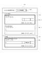
- the detection result output unit 26 can display a section in which a local alteration is detected, as shown in FIG.
- the screen 110 includes an area 112 for displaying a video timeline and an area 114 for displaying a degree of difference between videos.
- a video timeline 120 is displayed in the area 112, and a section 122 in which a different area is detected is displayed on the timeline 120. Further, a thumbnail image 124 in this section 122 is displayed below the section 122 in which the different area is detected.
- the detection result output unit 26 can display the thumbnail image 124 by referring to the video DB 32, for example.
- the different area detection unit 24 may include the thumbnail image of the input video in the section in which the different area is detected in the detection information. In this case, the detection result output unit 26 can also use the thumbnail image included in the detection information without referring to the video DB 32.
- a difference degree graph 130 is displayed in the area 114.
- the time axis that is the horizontal axis of the graph 130 is aligned with the time axis of the time line 120. Therefore, as shown in FIG. 13, the section 132 having a high degree of difference in the graph 130 and the section 122 in which the different area displayed on the timeline 120 is detected have the same time zone.
- the detection result output unit 26 displays the screen 140 shown in FIG. Is output.
- the screen 140 includes areas 142 and 143 in which the original video and the input video in the selected section are displayed.
- the detection result output unit 26 acquires the section information of the selected section from the detection information, reproduces the original video in the section from the video DB 32 and displays it in the area 142, and displays the input video in the section in the area 143.
- It is assumed that the input video is stored in a predetermined storage area (input video storage unit) inside or outside the different area detection system 10.
- the detection result output part 26 can display the frames 144 and 145 which show the position of the detected different area on the video displayed on the areas 142 and 143.
- the display of “frame” is an example, and any display method for easily identifying the position of the different area can be adopted.
- the detection result output unit 26 may output a 3D image so that the position of the different area can be identified.
- FIG. 15 shows images 146-1 and 146-2 displayed in the area 142 shown in FIG.
- the video 146-1 is a video for the left eye, and the area indicated by the frame 144 in FIG. 14 is shifted to the right and displayed in the area 147-1.
- the video 146-2 is a video for the right eye, and the area shown by the frame 144 in FIG. 14 is shifted to the left and displayed in the area 147-2.
- Such videos 146-1 and 146-2 are displayed as left-eye and right-eye videos in the area 142 shown in FIG. 14, respectively, so that the different areas can be displayed in three dimensions.
- the video displayed in the region 143 can be displayed in a three-dimensional manner in the same manner.
- the video is displayed so that the position of the different area can be identified, it is necessary to visually compare all the areas in the video displayed in the areas 142 and 143 when checking the difference between the videos. However, it is only necessary to compare the areas where the positions of the different areas can be identified, and the workload can be reduced.
- the detection result output unit 26 can estimate the original video of the modification source and display a section in which local modification has occurred between the estimated original video and the input video. For example, the detection result output unit 26 can display a screen as shown in FIG.
- the screen 150 shown in FIG. 16 includes an area 152 in which information related to an original video that is a candidate for modification source is displayed, and an area 154 in which information related to an input video is displayed. As shown in FIG. 16, the area 154 is provided with an area 156 in which information related to the input video is displayed. In addition, the area 152 is provided with areas 158-1 and 158-2 in which information about two original videos that are candidates for modification sources for the input video is displayed.
- the detection result output unit 26 is based on the detection information stored in the detection information storage unit 25 and the information stored in the feature amount DB 30. Estimate the original video of the modification source.
- the method of estimating the original video of the modification source can be selected using, for example, a list box 160 as shown in FIG.
- the detection result output unit 26 estimates an original video as a modification source from a plurality of original videos according to the selected method.
- the modification source for example, a method that prioritizes a video that matches the input video, that is, a video that takes a long time to be determined to be identical, or a method that prioritizes a video having a high similarity to the input video There is a method of giving priority to a video that does not cause a contradiction in the context of the creation date and time with the input video.
- the similarity information stored in the detection information storage unit 25 can be used for the similarity with the input video.
- the match time with the input video is selected as the estimation method of the modification source.
- the match time between the original video and the input video shown in the region 158-1 is 5 minutes
- the match time between the original video and the input video shown in the region 158-2 is 12 minutes. Therefore, the detection result output unit 26 estimates the original video shown in the area 158-2 as a modification source, and can identify the estimated original video of the modification source by, for example, highlighting the area 158-2. it's shown.
- the detection result output unit 26 displays the section in which the local modification is performed from the estimated original video of the modification source in an input video so as to be identifiable. For example, as shown in FIG. 16, the detection result output unit 26 displays the timeline of the original video and the input video with the time axis aligned, and then from the estimated modification source on the timeline of the input video. Displays the section where local modification was performed. Further, as shown in FIG. 16, the detection result output unit 26 can display the section in which the modification is “local modification” along with the section in which the local modification has been performed.
- the detection result output unit 26 outputs the screen 140 shown in FIG. The input video and the original video are displayed.
- the detection result output unit 26 inputs the original video of the modification source estimated by the selected estimation method. A section in which local modification has occurred with the video is displayed. Further, even when another original video is selected on the screen 150 by clicking or the like instead of changing the estimation method, the detection result output unit 26 causes local modification using the selected original video as a modification source. Display the interval. For example, in the screen 150 shown in FIG. 16, when the region 158-1 is selected by clicking or the like, as shown in FIG. 17, a local alteration occurs with the original video shown in the region 158-1 as the alteration source. The current section is displayed.
- the section in which the local modification occurs between the original video estimated as the modification source and the input video is displayed. Can do. Then, by selecting the displayed section, the video in this section can be confirmed. Therefore, when there are a plurality of original videos that are candidates for the modification source for the input video, it is possible to reduce the work load when confirming the modification content.
- the detection result output unit 26 makes it easy to understand which shot has undergone modification when displaying a section in which local modification has occurred between the original video estimated as the modification source and the input video. can do.
- the detection result output unit 26 can display a screen as shown in FIG.
- the thumbnail image 190 of the original video is displayed in the area 182
- the thumbnail image 192 of the input video is displayed in the area 184.
- it is a common technique to generate the thumbnail image by, for example, dividing the target video into shots. This shot division can be performed, for example, by detecting the timing when the feature vector changes greatly in the frame image included in the video. Then, a thumbnail image is generated from a representative frame image in each shot.
- the detection result output unit 26 may further perform shot division for a shot in which local modification is detected among shots divided by a general method, and generate a thumbnail image depending on the presence or absence of local modification. it can.
- the detection result output unit 26 performs a further shot division depending on the presence or absence of the local modification in each shot, thereby performing the local modification. Shots that match the timing can be generated. And the detection result output part 26 can display the thumbnail image 200 of the shot of the timing when local modification was performed, for example. Further, the detection result output unit 26 can display the information 202 that can identify that “local modification” has occurred in this section, along with the thumbnail image 200 of the shot at the timing when the local modification has been performed. The same applies to the other shots 196, 198.
- general shot division processing may be performed before being input to the different area detection system 10 or may be performed by a shot division unit provided in the different area detection system 10. .
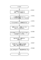
- FIG. 19 is a flowchart illustrating an example of a different area detection process in the different area detection system 10.
- the feature quantity extraction unit 20 extracts a feature quantity vector for each frame image of the input video and stores it in the feature quantity storage unit 21 (S1901).
- the feature amount comparison unit 70 compares the feature amount vector of the input video stored in the feature amount storage unit 21 with the feature amount vector of the original video stored in the feature amount DB 30 (S1902).
- the frame selection unit 72 selects identical frame images based on the comparison result from the feature amount comparison unit 70 (S1903).
- the difference information output unit 74 stores the difference vector for the selected frame image in the difference information storage unit 23 (S1904).
- the region mapping unit 80 maps the difference value to the region corresponding to the dimension in which the difference is generated in the feature amount based on the difference vector stored in the difference information storage unit 23 (S1905).
- the smoothing unit 82 smoothes the mapped difference value in the time and space directions (S1906).
- the area detecting unit 84 detects a different area between the input video and the original video based on the smoothed difference value, and stores the detection information in the detection information storage unit 25 (S1907).
- the detection result output unit 26 outputs information indicating a different area between the identical input video and the original video based on the detection information stored in the detection information storage unit 25 (S1908). .
- the difference area detection system 10 of the present embodiment has been described above. According to the different area detection system 10, instead of simply comparing the distances between the feature quantity vectors, the difference between the feature quantities for each dimension of the feature quantity vector is mapped to the partial area corresponding to each dimension, thereby making the same It is possible to detect a difference area between images having a characteristic.
- the different area detection system 10 it is possible to specify a section having the sameness between the images to be compared, and to detect the different area in the specified section.
- the different area detection system 10 it is possible to detect a different area in consideration of the dimension of the difference vector or the weight set for each area. For example, if the feature vector used to determine the identity more closely reflects the feature of the central part than the peripheral part of the image area, the detection of the peripheral part The weight of the area may be increased. For example, since a telop is often added to the lower part of the image area, increasing the weight of the lower part area is effective in detecting a different area between videos having a different telop. . In addition, for example, even when there is identity between videos and there is no local difference, the difference in the outermost peripheral portion of the image area may be large. For this reason, the weight of the outermost peripheral portion of the image area may be lowered.
- the position of the detected different area can be displayed in an identifiable manner. Accordingly, the user can easily confirm the position of the different area between identical videos.
- the different area detection system 10 it is possible to display a section in which a different area is generated in the video in an identifiable manner. Therefore, when the user checks the content that differs between videos, the user only has to check the video of the section, not the entire video, so the workload can be reduced.
- this embodiment is for making an understanding of this invention easy, and is not for limiting and interpreting this invention.
- the present invention can be changed / improved without departing from the spirit thereof, and the present invention includes equivalents thereof.
- a part or all of the present embodiment can be described as in the following supplementary notes, but is not limited thereto.
- (Supplementary Note 1) A first feature vector that is a set of feature amounts corresponding to each of a plurality of partial regions in the first image, and a feature corresponding to each of the plurality of partial regions in the second image.
- a difference information generation unit that generates inter-image difference information indicating a difference for each partial region of the feature amount between the first and second images, based on a second feature amount vector that is a set of amounts. Detection information indicating a detection result by detecting a different area which is an image area having a difference between the first and second images based on the difference in each partial area indicated by the inter-image difference information.
- a different area detection system that outputs a different area detection unit.
- (Additional remark 2) It is a different area detection system of Additional remark 1, Comprising: The said partial area contains at least 1 division area, The said different area detection part of each partial area is based on the said difference information between images.
- a different area detection system that detects the different area in units of the divided areas by assigning a difference value corresponding to the difference to each divided area.
- region detection system of Additional remark 1 Comprising: A said 1st image is a 1st frame image which comprises a 1st image
- the difference information generation unit generates the inter-image difference information for a plurality of pairs of the first and second images.
- the different area detection unit detects the different area in the first and second videos based on the inter-image difference information for the plurality of pairs of the first and second images. system. (Additional remark 4) It is a different area
- the divided regions By assigning a difference value corresponding to the difference to each of the divided regions and smoothing the difference values in a plurality of pairs of the first and second images between frame images, the divided regions as a unit A different area detection system for detecting the different area.
- the said different area detection part smoothes the said difference value in several pairs of the said 1st and 2nd image within a frame image.
- a different area detection system for detecting the different area (Supplementary note 6)
- the different area detection system according to any one of supplementary notes 3 to 5, wherein the difference information generation unit includes a plurality of the first feature quantity vectors and a plurality of the second feature quantities.
- Difference area detection system Based on the vector, a plurality of pairs of the first and second images having a feature vector difference smaller than a predetermined reference is selected, and the inter-image difference information in the selected plurality of pairs is output.
- Difference area detection system (Supplementary note 7) The different region detection system according to any one of supplementary notes 3 to 6, wherein the different region detection unit includes a weight set for each partial region, the first and second A different area detection system that detects the different area based on the difference values in a plurality of pairs of images.
- the different area detection system according to any one of supplementary notes 3 to 7, wherein the difference information generation unit includes a plurality of the first feature quantity vectors in the first video, Based on the plurality of second feature amount vectors in each of the second videos, the first video and the second video of one of the plurality of second videos, A different area detection system for selecting a plurality of pairs of first and second images.
- generation part is a plurality of said 1st feature-value vector in each of several said 1st image
- a different area detection system for selecting a plurality of pairs of the first and second images in two videos.
- the different region detection system according to any one of supplementary notes 1 to 9, wherein the position of the different region between the first and second images can be identified based on the detection information.
- a different area detection system further comprising a detection result output unit for displaying.
- the different area detection system according to any one of supplementary notes 3 to 9, wherein the position of the different area between the first and second images can be identified based on the detection information.
- a different area detection system further comprising a detection result output unit for displaying.
- a detection result output unit for displaying.
- the said different area detection part uses the information which shows the area in which the said different area was detected between the said 1st and 2nd image
- the detection result output unit displays the section in which the different area is detected in an identifiable manner based on the detection information.
- the said different area detection part includes the information which shows the degree of difference in the said different area in the said detection information, and outputs the said detection result output part Is a different area detection system for displaying the degree of difference in the different area in an identifiable manner based on the detection information.
- the said detection result output part is the said 1st and 2nd in the said area according to the user input which selects the area where the said different area was detected. System for displaying different areas.
- a second feature quantity vector that is a set of quantities inter-image difference information indicating a difference for each of the partial areas of the feature quantity between the first and second images is generated, and Based on the difference in each partial area indicated by the difference information, a difference area which is an image area having a difference between the first and second images is detected, and detection information indicating a detection result is output.
- Area detection method is indicating a difference for each of the partial areas of the feature quantity between the first and second images.
Landscapes
- Engineering & Computer Science (AREA)
- Physics & Mathematics (AREA)
- General Physics & Mathematics (AREA)
- Multimedia (AREA)
- Theoretical Computer Science (AREA)
- Computer Vision & Pattern Recognition (AREA)
- Image Analysis (AREA)
- Information Retrieval, Db Structures And Fs Structures Therefor (AREA)
Abstract
Description
(付記1)第1の画像内における複数の部分領域のそれぞれに対応する特徴量の集合である第1の特徴量ベクトルと、第2の画像内における前記複数の部分領域のそれぞれに対応する特徴量の集合である第2の特徴量ベクトルとに基づいて、前記第1及び第2の画像間における、前記特徴量の前記部分領域ごとの差分を示す画像間差分情報を生成する差分情報生成部と、前記画像間差分情報によって示される、各部分領域における前記差分に基づいて、前記第1及び第2の画像間において相違のある画像領域である相違領域を検出し、検出結果を示す検出情報を出力する相違領域検出部と、を備える相違領域検出システム。
(付記2)付記1に記載の相違領域検出システムであって、前記部分領域は、少なくとも1つの分割領域を含み、前記相違領域検出部は、前記画像間差分情報に基づいて、各部分領域の各分割領域に対して前記差分に応じた差分値を割り当てることにより、前記分割領域を単位として前記相違領域を検出する、相違領域検出システム。
(付記3)付記1に記載の相違領域検出システムであって、前記第1の画像は、第1の映像を構成する第1のフレーム画像であり、前記第2の画像は、第2の映像を構成する、前記第1のフレーム画像に対応する第2のフレーム画像であり、前記差分情報生成部は、前記第1及び第2の画像の複数の対に対して前記画像間差分情報を生成し、前記相違領域検出部は、前記第1及び第2の画像の複数の対に対する前記画像間差分情報に基づいて、前記第1及び第2の映像における前記相違領域を検出する、相違領域検出システム。
(付記4)付記3に記載の相違領域検出システムであって、前記部分領域は、少なくとも1つの分割領域を含み、前記相違領域検出部は、前記画像間差分情報に基づいて、各部分領域内の各分割領域に対して前記差分に応じた差分値を割り当て、前記第1及び第2の画像の複数の対における前記差分値をフレーム画像間で平滑化することにより、前記分割領域を単位として前記相違領域を検出する、相違領域検出システム。
(付記5)付記3または4に記載の相違領域検出システムであって、前記相違領域検出部は、前記第1及び第2の画像の複数の対における前記差分値をフレーム画像内で平滑化することにより、前記相違領域を検出する、相違領域検出システム。
(付記6)付記3~5の何れか一項に記載の相違領域検出システムであって、前記差分情報生成部は、複数の前記第1の特徴量ベクトルと、複数の前記第2の特徴量ベクトルとに基づいて、特徴量ベクトルの差分が所定の基準より小さい、前記第1及び第2の画像の複数の対を選択し、前記選択された複数の対における前記画像間差分情報を出力する、相違領域検出システム。
(付記7)付記3~6の何れか一項に記載の相違領域検出システムであって、前記相違領域検出部は、前記部分領域ごとに設定された重みづけと、前記第1及び第2の画像の複数の対における前記差分値とに基づいて、前記相違領域を検出する、相違領域検出システム。
(付記8)付記3~7の何れか一項に記載の相違領域検出システムであって、前記差分情報生成部は、前記第1の映像における複数の前記第1の特徴量ベクトルと、複数の前記第2の映像のそれぞれにおける複数の前記第2の特徴量ベクトルとに基づいて、前記第1の映像と、前記複数の第2の映像のうちの1つの第2の映像とにおける、前記第1及び第2の画像の複数の対を選択する、相違領域検出システム。
(付記9)付記8に記載の相違領域検出システムであって、前記差分情報生成部は、複数の前記第1の映像のそれぞれにおける複数の前記第1の特徴量ベクトルと、複数の前記第2の映像のそれぞれにおける複数の前記第2の特徴量ベクトルとに基づいて、前記複数の第1の映像のうちの1つの第1の映像と、前記複数の第2の映像のうちの1つの第2の映像とにおける、前記第1及び第2の画像の複数の対を選択する、相違領域検出システム。
(付記10)付記1~9の何れか一項に記載の相違領域検出システムであって、前記検出情報に基づいて、前記第1及び第2の画像間における前記相違領域の位置を識別可能に表示する検出結果出力部をさらに備える、相違領域検出システム。
(付記11)付記3~9の何れか一項に記載の相違領域検出システムであって、前記検出情報に基づいて、前記第1及び第2の映像間における前記相違領域の位置を識別可能に表示する検出結果出力部をさらに備える、相違領域検出システム。
(付記12)付記11に記載の相違領域検出システムであって、前記相違領域検出部は、前記第1及び第2の映像間において前記相違領域が検出された区間を示す情報を前記検出情報に含めて出力し、前記検出結果出力部は、前記検出情報に基づいて、前記相違領域が検出された区間を識別可能に表示する、相違領域検出システム。
(付記13)付記11または12に記載の相違領域検出システムであって、前記相違領域検出部は、前記相違領域における相違の度合い示す情報を前記検出情報に含めて出力し、前記検出結果出力部は、前記検出情報に基づいて、前記相違領域における相違の度合いを識別可能に表示する、相違領域検出システム。
(付記14)付記12に記載の相違領域検出システムであって、前記検出結果出力部は、前記相違領域が検出された区間を選択するユーザ入力に応じて、該区間における前記第1及び第2の映像を表示する、相違領域検出システム。
(付記15)第1の画像内における複数の部分領域のそれぞれに対応する特徴量の集合である第1の特徴量ベクトルと、第2の画像内における前記複数の部分領域のそれぞれに対応する特徴量の集合である第2の特徴量ベクトルとに基づいて、前記第1及び第2の画像間における、前記特徴量の前記部分領域ごとの差分を示す画像間差分情報を生成し、前記画像間差分情報によって示される、各部分領域における前記差分に基づいて、前記第1及び第2の画像間において相違のある画像領域である相違領域を検出し、検出結果を示す検出情報を出力する、相違領域検出方法。
20 特徴量抽出部
21 特徴量記憶部
22 差分情報生成部
23 差分情報記憶部
24 相違領域検出部
25 検出情報記憶部
26 検出結果出力部
30 特徴量データベース
32 映像データベース
70 特徴量比較部
72 フレーム選択部
74 差分情報出力部
80 領域マッピング部
82 平滑化部
84 領域検出部
Claims (15)
- 第1の画像内における複数の部分領域のそれぞれに対応する特徴量の集合である第1の特徴量ベクトルと、第2の画像内における前記複数の部分領域のそれぞれに対応する特徴量の集合である第2の特徴量ベクトルとに基づいて、前記第1及び第2の画像間における、前記特徴量の前記部分領域ごとの差分を示す画像間差分情報を生成する差分情報生成部と、
前記画像間差分情報によって示される、各部分領域における前記差分に基づいて、前記第1及び第2の画像間において相違のある画像領域である相違領域を検出し、検出結果を示す検出情報を出力する相違領域検出部と、
を備える相違領域検出システム。 - 請求項1に記載の相違領域検出システムであって、
前記部分領域は、少なくとも1つの分割領域を含み、
前記相違領域検出部は、前記画像間差分情報に基づいて、各部分領域の各分割領域に対して前記差分に応じた差分値を割り当てることにより、前記分割領域を単位として前記相違領域を検出する、
相違領域検出システム。 - 請求項1に記載の相違領域検出システムであって、
前記第1の画像は、第1の映像を構成する第1のフレーム画像であり、
前記第2の画像は、第2の映像を構成する、前記第1のフレーム画像に対応する第2のフレーム画像であり、
前記差分情報生成部は、前記第1及び第2の画像の複数の対に対して前記画像間差分情報を生成し、
前記相違領域検出部は、前記第1及び第2の画像の複数の対に対する前記画像間差分情報に基づいて、前記第1及び第2の映像における前記相違領域を検出する、
相違領域検出システム。 - 請求項3に記載の相違領域検出システムであって、
前記部分領域は、少なくとも1つの分割領域を含み、
前記相違領域検出部は、
前記画像間差分情報に基づいて、各部分領域内の各分割領域に対して前記差分に応じた差分値を割り当て、
前記第1及び第2の画像の複数の対における前記差分値をフレーム画像間で平滑化することにより、前記分割領域を単位として前記相違領域を検出する、
相違領域検出システム。 - 請求項3または4に記載の相違領域検出システムであって、
前記相違領域検出部は、前記第1及び第2の画像の複数の対における前記差分値をフレーム画像内で平滑化することにより、前記相違領域を検出する、
相違領域検出システム。 - 請求項3~5の何れか一項に記載の相違領域検出システムであって、
前記差分情報生成部は、
複数の前記第1の特徴量ベクトルと、複数の前記第2の特徴量ベクトルとに基づいて、特徴量ベクトルの差分が所定の基準より小さい、前記第1及び第2の画像の複数の対を選択し、
前記選択された複数の対における前記画像間差分情報を出力する、
相違領域検出システム。 - 請求項3~6の何れか一項に記載の相違領域検出システムであって、
前記相違領域検出部は、前記部分領域ごとに設定された重みづけと、前記第1及び第2の画像の複数の対における前記差分値とに基づいて、前記相違領域を検出する、
相違領域検出システム。 - 請求項3~7の何れか一項に記載の相違領域検出システムであって、
前記差分情報生成部は、前記第1の映像における複数の前記第1の特徴量ベクトルと、複数の前記第2の映像のそれぞれにおける複数の前記第2の特徴量ベクトルとに基づいて、前記第1の映像と、前記複数の第2の映像のうちの1つの第2の映像とにおける、前記第1及び第2の画像の複数の対を選択する、
相違領域検出システム。 - 請求項8に記載の相違領域検出システムであって、
前記差分情報生成部は、複数の前記第1の映像のそれぞれにおける複数の前記第1の特徴量ベクトルと、複数の前記第2の映像のそれぞれにおける複数の前記第2の特徴量ベクトルとに基づいて、前記複数の第1の映像のうちの1つの第1の映像と、前記複数の第2の映像のうちの1つの第2の映像とにおける、前記第1及び第2の画像の複数の対を選択する、
相違領域検出システム。 - 請求項1~9の何れか一項に記載の相違領域検出システムであって、
前記検出情報に基づいて、前記第1及び第2の画像間における前記相違領域の位置を識別可能に表示する検出結果出力部をさらに備える、
相違領域検出システム。 - 請求項3~9の何れか一項に記載の相違領域検出システムであって、
前記検出情報に基づいて、前記第1及び第2の映像間における前記相違領域の位置を識別可能に表示する検出結果出力部をさらに備える、
相違領域検出システム。 - 請求項11に記載の相違領域検出システムであって、
前記相違領域検出部は、前記第1及び第2の映像間において前記相違領域が検出された区間を示す情報を前記検出情報に含めて出力し、
前記検出結果出力部は、前記検出情報に基づいて、前記相違領域が検出された区間を識別可能に表示する、
相違領域検出システム。 - 請求項11または12に記載の相違領域検出システムであって、
前記相違領域検出部は、前記相違領域における相違の度合い示す情報を前記検出情報に含めて出力し、
前記検出結果出力部は、前記検出情報に基づいて、前記相違領域における相違の度合いを識別可能に表示する、
相違領域検出システム。 - 請求項12に記載の相違領域検出システムであって、
前記検出結果出力部は、前記相違領域が検出された区間を選択するユーザ入力に応じて、該区間における前記第1及び第2の映像を表示する、
相違領域検出システム。 - 第1の画像内における複数の部分領域のそれぞれに対応する特徴量の集合である第1の特徴量ベクトルと、第2の画像内における前記複数の部分領域のそれぞれに対応する特徴量の集合である第2の特徴量ベクトルとに基づいて、前記第1及び第2の画像間における、前記特徴量の前記部分領域ごとの差分を示す画像間差分情報を生成し、
前記画像間差分情報によって示される、各部分領域における前記差分に基づいて、前記第1及び第2の画像間において相違のある画像領域である相違領域を検出し、検出結果を示す検出情報を出力する、
相違領域検出方法。
Priority Applications (4)
| Application Number | Priority Date | Filing Date | Title |
|---|---|---|---|
| CN201180066973.XA CN103348380B (zh) | 2011-02-10 | 2011-11-28 | 差异区域检测系统和差异区域检测方法 |
| US13/983,932 US9424469B2 (en) | 2011-02-10 | 2011-11-28 | Differing region detection system and differing region detection method |
| JP2012556754A JP5991488B2 (ja) | 2011-02-10 | 2011-11-28 | 相違領域検出システム及び相違領域検出方法 |
| EP11858173.5A EP2674911B1 (en) | 2011-02-10 | 2011-11-28 | Differing region detection system and differing region detection method |
Applications Claiming Priority (2)
| Application Number | Priority Date | Filing Date | Title |
|---|---|---|---|
| JP2011027429 | 2011-02-10 | ||
| JP2011-027429 | 2011-02-10 |
Publications (1)
| Publication Number | Publication Date |
|---|---|
| WO2012108088A1 true WO2012108088A1 (ja) | 2012-08-16 |
Family
ID=46638317
Family Applications (1)
| Application Number | Title | Priority Date | Filing Date |
|---|---|---|---|
| PCT/JP2011/077376 Ceased WO2012108088A1 (ja) | 2011-02-10 | 2011-11-28 | 相違領域検出システム及び相違領域検出方法 |
Country Status (5)
| Country | Link |
|---|---|
| US (1) | US9424469B2 (ja) |
| EP (1) | EP2674911B1 (ja) |
| JP (1) | JP5991488B2 (ja) |
| CN (1) | CN103348380B (ja) |
| WO (1) | WO2012108088A1 (ja) |
Cited By (2)
| Publication number | Priority date | Publication date | Assignee | Title |
|---|---|---|---|---|
| US9633278B2 (en) | 2012-12-28 | 2017-04-25 | Nec Corporation | Object identification device, method, and storage medium |
| WO2019156043A1 (ja) * | 2018-02-06 | 2019-08-15 | 日本電信電話株式会社 | コンテンツ判定装置、コンテンツ判定方法、及びプログラム |
Families Citing this family (8)
| Publication number | Priority date | Publication date | Assignee | Title |
|---|---|---|---|---|
| US9792528B2 (en) * | 2012-01-30 | 2017-10-17 | Nec Corporation | Information processing system, information processing method, information processing apparatus and control method and control program thereof, and communication terminal and control method and control program thereof |
| US9813762B2 (en) * | 2015-11-16 | 2017-11-07 | Arris Enterprises Llc | Creating hash values indicative of differences in images |
| CN107248296B (zh) * | 2017-07-13 | 2020-04-24 | 南京航空航天大学 | 一种基于无人机和时序特征的视频交通流量统计方法 |
| US10192319B1 (en) * | 2017-07-27 | 2019-01-29 | Nanning Fugui Precision Industrial Co., Ltd. | Surveillance method and computing device using the same |
| CN108303037B (zh) * | 2018-01-31 | 2020-05-08 | 广东工业大学 | 一种基于点云分析的工件表面形状差异的检测方法及装置 |
| CN109635669B (zh) * | 2018-11-19 | 2021-06-29 | 北京致远慧图科技有限公司 | 图像分类方法、装置及分类模型的训练方法、装置 |
| WO2020208693A1 (ja) * | 2019-04-08 | 2020-10-15 | 株式会社 AI Samurai | 文書情報評価装置および文書情報評価方法並びに文書情報評価プログラム |
| CN110222590B (zh) * | 2019-05-15 | 2021-05-25 | 北京字节跳动网络技术有限公司 | 图像差异判断方法、装置及电子设备 |
Citations (6)
| Publication number | Priority date | Publication date | Assignee | Title |
|---|---|---|---|---|
| JP2000242795A (ja) * | 1999-02-25 | 2000-09-08 | Nippon Telegr & Teleph Corp <Ntt> | 映像差分検出装置、映像差分検出方法およびこの方法を記録した記録媒体 |
| JP2005202921A (ja) * | 2003-12-17 | 2005-07-28 | Shibasoku:Kk | 動きベクトル検出装置 |
| JP2007279813A (ja) * | 2006-04-03 | 2007-10-25 | Fuji Xerox Co Ltd | 画像処理装置及びプログラム |
| JP2008282316A (ja) * | 2007-05-14 | 2008-11-20 | Yahoo Japan Corp | 動画像比較装置、動画像比較方法、及び動画像比較プログラム |
| WO2010084714A1 (ja) | 2009-01-23 | 2010-07-29 | 日本電気株式会社 | 画像識別子抽出装置 |
| JP2011027429A (ja) | 2009-07-21 | 2011-02-10 | Kirin Holdings Co Ltd | 液体クロマトグラフィーを用いたグリコアルカロイド類の精製および分析法 |
Family Cites Families (6)
| Publication number | Priority date | Publication date | Assignee | Title |
|---|---|---|---|---|
| US5436653A (en) * | 1992-04-30 | 1995-07-25 | The Arbitron Company | Method and system for recognition of broadcast segments |
| US6937773B1 (en) * | 1999-10-20 | 2005-08-30 | Canon Kabushiki Kaisha | Image encoding method and apparatus |
| KR100524077B1 (ko) * | 2003-11-13 | 2005-10-26 | 삼성전자주식회사 | 중간 영상 합성을 위한 시간적 평활화 장치 및 방법 |
| JP2006268825A (ja) * | 2005-02-28 | 2006-10-05 | Toshiba Corp | オブジェクト検出装置、学習装置、オブジェクト検出システム、方法、およびプログラム |
| US8514933B2 (en) * | 2005-03-01 | 2013-08-20 | Qualcomm Incorporated | Adaptive frame skipping techniques for rate controlled video encoding |
| CN101473657A (zh) | 2006-06-20 | 2009-07-01 | 皇家飞利浦电子股份有限公司 | 产生视频信号的指纹 |
-
2011
- 2011-11-28 JP JP2012556754A patent/JP5991488B2/ja active Active
- 2011-11-28 US US13/983,932 patent/US9424469B2/en active Active
- 2011-11-28 EP EP11858173.5A patent/EP2674911B1/en not_active Not-in-force
- 2011-11-28 WO PCT/JP2011/077376 patent/WO2012108088A1/ja not_active Ceased
- 2011-11-28 CN CN201180066973.XA patent/CN103348380B/zh not_active Expired - Fee Related
Patent Citations (6)
| Publication number | Priority date | Publication date | Assignee | Title |
|---|---|---|---|---|
| JP2000242795A (ja) * | 1999-02-25 | 2000-09-08 | Nippon Telegr & Teleph Corp <Ntt> | 映像差分検出装置、映像差分検出方法およびこの方法を記録した記録媒体 |
| JP2005202921A (ja) * | 2003-12-17 | 2005-07-28 | Shibasoku:Kk | 動きベクトル検出装置 |
| JP2007279813A (ja) * | 2006-04-03 | 2007-10-25 | Fuji Xerox Co Ltd | 画像処理装置及びプログラム |
| JP2008282316A (ja) * | 2007-05-14 | 2008-11-20 | Yahoo Japan Corp | 動画像比較装置、動画像比較方法、及び動画像比較プログラム |
| WO2010084714A1 (ja) | 2009-01-23 | 2010-07-29 | 日本電気株式会社 | 画像識別子抽出装置 |
| JP2011027429A (ja) | 2009-07-21 | 2011-02-10 | Kirin Holdings Co Ltd | 液体クロマトグラフィーを用いたグリコアルカロイド類の精製および分析法 |
Non-Patent Citations (1)
| Title |
|---|
| See also references of EP2674911A4 |
Cited By (3)
| Publication number | Priority date | Publication date | Assignee | Title |
|---|---|---|---|---|
| US9633278B2 (en) | 2012-12-28 | 2017-04-25 | Nec Corporation | Object identification device, method, and storage medium |
| WO2019156043A1 (ja) * | 2018-02-06 | 2019-08-15 | 日本電信電話株式会社 | コンテンツ判定装置、コンテンツ判定方法、及びプログラム |
| JP2019139326A (ja) * | 2018-02-06 | 2019-08-22 | 日本電信電話株式会社 | コンテンツ判定装置、コンテンツ判定方法、及びプログラム |
Also Published As
| Publication number | Publication date |
|---|---|
| US20130322696A1 (en) | 2013-12-05 |
| EP2674911B1 (en) | 2021-03-03 |
| CN103348380B (zh) | 2016-08-10 |
| CN103348380A (zh) | 2013-10-09 |
| EP2674911A1 (en) | 2013-12-18 |
| JP5991488B2 (ja) | 2016-09-14 |
| EP2674911A4 (en) | 2014-12-31 |
| US9424469B2 (en) | 2016-08-23 |
| JPWO2012108088A1 (ja) | 2014-07-03 |
Similar Documents
| Publication | Publication Date | Title |
|---|---|---|
| JP5991488B2 (ja) | 相違領域検出システム及び相違領域検出方法 | |
| JP4337064B2 (ja) | 情報処理装置、情報処理方法、およびプログラム | |
| US10244163B2 (en) | Image processing apparatus that generates a virtual viewpoint image, image generation method, and non-transitory computer-readable storage medium | |
| JP6378292B2 (ja) | 動画ファイル中の対象物を識別する方法 | |
| US9684818B2 (en) | Method and apparatus for providing image contents | |
| JP5088164B2 (ja) | 画像処理装置および方法、プログラム、並びに記録媒体 | |
| US20190188729A1 (en) | System and method for detecting counterfeit product based on deep learning | |
| JP2015536094A (ja) | ビデオシーン検出 | |
| CN103686272B (zh) | 图像处理装置及方法 | |
| KR20190086781A (ko) | 비디오 프레임의 다수의 부분들에 대한 지문들을 생성함으로써 입체 비디오들을 검출하기 위한 방법들, 시스템들, 및 매체들 | |
| JP2021111228A (ja) | 学習装置、学習方法、及びプログラム | |
| CN113297416B (zh) | 视频数据存储方法、装置、电子设备和可读存储介质 | |
| KR102468718B1 (ko) | 심층신경망을 이용하여 3차원 디지털 트윈 공간을 제공하기 위한 장치 및 방법 | |
| US20160027050A1 (en) | Method of providing advertisement service using cloud album | |
| CN102479384B (zh) | 图像处理方法和装置 | |
| JP2014110020A (ja) | 画像処理装置、画像処理方法および画像処理プログラム | |
| JP2019061488A (ja) | 表示プログラム、表示方法、及び表示装置 | |
| Mohiuddin et al. | Duplicate frame detection in forged videos using sequence matching | |
| JP5702269B2 (ja) | 並列映像解析装置、並列映像解析方法及び並列映像解析プログラム | |
| JP4997179B2 (ja) | 画像処理装置、方法およびプログラム | |
| KR100981125B1 (ko) | 동영상 처리 방법 및 그 장치 | |
| JP5699856B2 (ja) | 動画像処理装置、動画像処理方法及び動画像処理用コンピュータプログラム | |
| US9591220B2 (en) | Selection apparatus, selection method, and storage medium | |
| JP5854232B2 (ja) | 映像間対応関係表示システム及び映像間対応関係表示方法 | |
| WO2016142965A1 (ja) | 映像処理装置、映像処理方法及び映像処理プログラムを記憶する記録媒体 |
Legal Events
| Date | Code | Title | Description |
|---|---|---|---|
| 121 | Ep: the epo has been informed by wipo that ep was designated in this application |
Ref document number: 11858173 Country of ref document: EP Kind code of ref document: A1 |
|
| WWE | Wipo information: entry into national phase |
Ref document number: 2011858173 Country of ref document: EP |
|
| WWE | Wipo information: entry into national phase |
Ref document number: 13983932 Country of ref document: US |
|
| ENP | Entry into the national phase |
Ref document number: 2012556754 Country of ref document: JP Kind code of ref document: A |
|
| NENP | Non-entry into the national phase |
Ref country code: DE |