WO2012108418A1 - N2ガスパージ装置におけるノズルユニット - Google Patents
N2ガスパージ装置におけるノズルユニット Download PDFInfo
- Publication number
- WO2012108418A1 WO2012108418A1 PCT/JP2012/052715 JP2012052715W WO2012108418A1 WO 2012108418 A1 WO2012108418 A1 WO 2012108418A1 JP 2012052715 W JP2012052715 W JP 2012052715W WO 2012108418 A1 WO2012108418 A1 WO 2012108418A1
- Authority
- WO
- WIPO (PCT)
- Prior art keywords
- nozzle
- gas
- foup
- gas supply
- exhaust
- Prior art date
- Legal status (The legal status is an assumption and is not a legal conclusion. Google has not performed a legal analysis and makes no representation as to the accuracy of the status listed.)
- Ceased
Links
Images


Classifications
-
- H—ELECTRICITY
- H10—SEMICONDUCTOR DEVICES; ELECTRIC SOLID-STATE DEVICES NOT OTHERWISE PROVIDED FOR
- H10P—GENERIC PROCESSES OR APPARATUS FOR THE MANUFACTURE OR TREATMENT OF DEVICES COVERED BY CLASS H10
- H10P72/00—Handling or holding of wafers, substrates or devices during manufacture or treatment thereof
- H10P72/10—Handling or holding of wafers, substrates or devices during manufacture or treatment thereof using carriers specially adapted therefor, e.g. front opening unified pods [FOUP]
- H10P72/19—Handling or holding of wafers, substrates or devices during manufacture or treatment thereof using carriers specially adapted therefor, e.g. front opening unified pods [FOUP] closed carriers
- H10P72/1924—Handling or holding of wafers, substrates or devices during manufacture or treatment thereof using carriers specially adapted therefor, e.g. front opening unified pods [FOUP] closed carriers characterised by atmosphere control
- H10P72/1926—Handling or holding of wafers, substrates or devices during manufacture or treatment thereof using carriers specially adapted therefor, e.g. front opening unified pods [FOUP] closed carriers characterised by atmosphere control characterised by the presence of atmosphere modifying elements inside or attached to the closed carrier
Definitions
- the present invention relates to an N2 gas purge apparatus provided with an N2 gas supply nozzle and an exhaust nozzle in a purge apparatus for purging a semiconductor wafer storage container (hereinafter referred to as “FOUP”) used in a mini-environment type semiconductor clean room with an N2 gas.
- FOUP semiconductor wafer storage container
- a mini-engineering method is generally used in which a wafer is stored in a FOUP, and is transported and handled between semiconductor manufacturing apparatuses without being exposed to the outside air.
- FOUP is equipped with a breathing filter unit on the bottom plate of the FOUP in order to make the internal pressure and the outside air pressure uniform when the atmospheric pressure changes during transportation and to prevent the FOUP from expanding and contracting.
- a breathing filter is attached to the breathing filter unit. The breathing filter is for preventing dust from entering the FOUP from the outside when the air enters and exits the FOUP.
- N2 gas purge is employed in a process in which the adhesion of moisture and chemical gas to the wafer surface in the FOUP causes a decrease in yield.
- the residual gas in the FOUP is driven out with high-purity N 2 gas and filled with N 2 gas, thereby protecting the wafer surface from contamination by moisture or chemical gas.
- each of the breathing filter units installed on the bottom plate of the N2 gas purge FOUP includes one type of N2 gas supply breathing filter unit and one type of exhaust breathing filter unit. Equipped.
- the breathing filter unit for N2 gas supply includes a valve that is opened only when N2 gas is supplied to the FOUP.
- the exhaust breathing filter unit includes a valve that is opened only when the residual gas in the FOUP is exhausted to the outside of the FOUP. After the inside of the FOUP is replaced with N2 gas, the respective valves are closed and sealed so that the N2 gas in the FOUP does not leak to the outside.
- the bottom plate of the N2 gas purge FOUP is equipped with various types of breathing filter units by FOUP force.
- the breathing filter unit on the N2 gas supply side has an upper end opening at the top of the cylindrical housing and an N2 gas supply side ventilation opening at the bottom.
- the upper end opening includes a filter
- the N2 gas supply side ventilation opening includes a shutter that is opened only when N2 gas is supplied into the breathing filter unit.
- the breathing filter unit on the residual gas exhaust side includes an upper end opening at the top of the cylindrical housing and a residual gas exhaust side ventilation opening at the bottom.
- the upper end opening is provided with a filter
- the residual gas exhaust side ventilation opening is provided with a shutter that is opened only when the residual gas in the breathing filter unit is discharged.
- the FOUP positioning kinema pins On the FOUP mounting surface of the N2 gas purge device, three sets of FOUP positioning kinema pins, two types of N2 gas supply nozzles for supplying N2 gas into the FOUP and exhaust nozzles for residual gas in the FOUP are installed. .
- the FOUP containing the semiconductor wafer is purged with N 2 gas
- the FOUP is mounted on the N 2 gas purge apparatus.
- the FOUP is positioned by the kinema pin.
- the N2 gas supply side vent opening of the breathing unit at the bottom of the F0UP is connected to the N2 gas supply nozzle.
- the residual gas exhaust side ventilation opening is connected to the exhaust nozzle.
- the N2 gas supplied from the N2 gas supply nozzle of the N2 gas purge apparatus enters the FOUP containing the semiconductor wafer from the N2 gas supply side ventilation opening of the breathing filter unit at the bottom of the FOUP.
- the residual gas inside the FOUP passes through the exhaust nozzle of the N2 purge device connected to the residual gas exhaust side ventilation opening of the breathing unit at the bottom of the F0UP and is sucked and discharged outside.
- FOUP In the semiconductor production line, FOUP is periodically washed with hot water and dried. At that time, since the FOUP is made of resin, it is gradually deformed.
- the FOUP is mounted on the purge device. Even if the FOUP is held at a fixed position with three sets of kinema pins, the FOUP that has been repeatedly washed and dried is distorted, and the bottom of the FOUP cannot be kept horizontal. .
- the breathing filter unit is replaced as a consumable item. Therefore, it is possible to easily attach the breathing filter unit of each company to the bottom of the FOUP, but it is not structured so as to keep the level accurately.
- the breathing filter unit 1 may have different specifications even with the same force, and there are various shapes of the N2 gas supply side ventilation opening and the residual gas exhaust side ventilation opening.
- the N2 gas purge apparatus has a problem that an N2 gas supply nozzle and an exhaust nozzle that can be connected to a new breathing filter must be newly prepared.
- the tip of the N2 gas supply nozzle and the tip of the exhaust nozzle, or the N2 gas supply side vent opening and the residual gas exhaust side vent opening use elastic rubber materials. In this case, since dust and outgas are generated, there is a problem of adversely affecting the semiconductor wafer process.
- the present invention is a nozzle unit that is applied to each nozzle of an N2 gas purge apparatus that includes an N2 gas supply nozzle and an exhaust nozzle for filling a FOUP (semiconductor wafer storage container) with N2 gas in a semiconductor manufacturing line.
- a breathing filter unit is provided at the bottom of the FOUP, and the breathing filter unit is provided with an N2 gas supply side ventilation opening and a residual gas exhaust side ventilation opening.
- the N2 gas is supplied into the FOUP by the N2 gas supply nozzle, the residual gas in the FOUP is discharged by the exhaust nozzle, and the inside of the FOUP is filled with the N2 gas.
- the nozzle unit includes a nozzle, a nozzle receiver, and an O-ring.
- the nozzle has a structure in which an upper end of the nozzle is in close contact with the ventilation opening of the breathing filter unit and a hemispherical seal is formed in the lower portion, and a gas passage extends through the upper and lower portions.
- the nozzle receiver includes a concave hemispherical seal portion for receiving and holding the hemispherical seal portion of the nozzle at an upper portion, and a gas passage at the center.
- a zero ring groove is provided in each of the nozzle and the nozzle receiver.
- a holding O-ring is provided on the nozzle and the nozzle receiver.
- the nozzle unit according to the present invention includes a nozzle, a nozzle receiver, and an O-ring.
- the nozzle has a structure in which an upper end of the nozzle is in close contact with the ventilation opening of the breathing filter unit and a hemispherical seal is formed in the lower portion, and a gas passage extends through the upper and lower portions.
- the nozzle receiver includes a concave hemispherical seal portion for receiving and holding the hemispherical seal portion of the nozzle at an upper portion, and a gas passage at the center. Further, in order to hold the nozzle in the nozzle receiver while maintaining the nozzle mobility, a zero ring groove is provided in each of the nozzle and the nozzle receiver.
- a holding O-ring is provided on the nozzle and the nozzle receiver. Therefore, the bottom of the FOUP is inclined by washing and drying, and as a result, even if the ventilation opening of the breathing filter unit is inclined, the nozzle tip is brought into close contact with the inclined ventilation opening by the rotation of the nozzle. Accordingly, outgas from the O-ring is blocked at the seal portion contact surface. Further, the outgas is not mixed into the gas passage but is discharged to the outside, so that the gas can be completely purged.
- the perspective view of the conventional N2 gas purge FOUP The FOUP and N2 gas supply side breathing filter unit longitudinal section. Sectional drawing of the residual gas exhaust side breathing filter unnoted.
- the perspective view of the N2 gas purge apparatus Sectional drawing of the flow of N2 gas and a residual gas when FOUP is mounted in the N2 gas purge apparatus equipped with the N2 gas supply nozzle and the residual gas exhaust nozzle, and the inside of FOUP is purged. Sectional drawing of the connection part of the N2 gas supply side nozzle and the N2 gas supply side ventilation
- gas_flowing opening of a breathing filter unit Sectional drawing of the N2 gas leak countermeasure part 2 from the connection part of the same N2 gas supply side nozzle and the N2 gas supply side ventilation
- Sectional drawing of the nozzle which concerns on this invention. Sectional drawing of the nozzle receptacle. Sectional drawing of the same O-ring. The nozzle assembly sectional drawing.
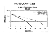
- FIG. 4 is a comparison diagram of measurement results of N2 gas purge time when the N2 gas purge apparatus is equipped with the N2 gas supply nozzle and the residual gas exhaust nozzle of the present invention and when the conventional N2 gas supply nozzle and the residual gas exhaust nozzle are equipped.
- FIG. 1 is a perspective view of a conventionally used FOUP.
- FIG. 2 is a longitudinal sectional view of the FOUP and N2 gas supply side breathing filter unit.
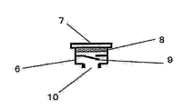
- FIG. 3 is a longitudinal sectional view of the residual gas exhaust side breathing filter unit.
- an N 2 gas supply side breathing filter unit 1 and a residual gas exhaust side breathing filter unit 6 are attached to the bottom 12 of the FOUP 11.
- the N2 gas supply side breathing filter unit 1 includes an upper end opening portion 2, a filter 3, and an N2 gas supply side ventilation opening 5, and an N2 gas supply side shutter 4 that is opened only when N2 gas is supplied.
- the exhaust side breathing filter unit 6 includes an upper end opening 7, a filter 8, and a residual gas exhaust side ventilation opening 10 and is formed with a residual gas exhaust side shutter 9 that is opened only when residual gas is exhausted. Yes.
- FIG. 4 is a perspective view of an N2 gas purge device 16 equipped with a conventional nozzle.
- the FOUP mounting portion 17 of the N2 gas purge device 16 is equipped with an N2 gas supply side nozzle 19 and a residual gas exhaust side nozzle 20, and three sets of kinema pins 18 are projected.
- the kinema pin 18 positions the FOUP 11 when the FOUP 11 is mounted.
- the N 2 gas purge device 16 is provided with an N 2 gas supply port 21 for supplying the N 2 gas 25 and a residual gas exhaust port 22 for exhausting the residual gas 26.
- an electromagnetic valve control panel 23 for operating an electromagnetic valve (not shown) inside the purge apparatus 16 is connected to the purge device 16 by a cable 24.
- FIG. 5 is a cross-sectional view showing the flow of the N2 gas 25 and the residual gas 26 when the FOUP 11 is mounted on the FOUP mounting portion 17 of the purge device 16 equipped with the conventional nozzle and N2 gas purge is performed.
- the FOUP 11 containing the semiconductor wafer 14 is mounted on the N 2 gas purge device 16. At this time, the FOUP 11 is positioned by the kinema bin 18.
- the N2 gas supply side ventilation opening 5 of the breathing units 1 and 6 at the bottom of the FOUP 11 is connected to the N2 gas supply nozzle 19.
- the residual gas exhaust side ventilation opening 10 is connected to the exhaust nozzle 20.
- the N2 gas 25 is supplied from the N2 gas supply nozzle 19 of the purge device 16 through the N2 gas supply port 21 from the N2 gas supply source 27. Then, the N 2 gas 25 enters the FOUP 11 in which the semiconductor wafer 14 is accommodated from the N 2 gas supply side ventilation opening 5 of the N 2 gas supply side breathing filter unit 1 at the bottom of the FOUP 11.
- the residual gas 26 in the FOUP 11 passes through the exhaust nozzle 20 and the residual gas exhaust port 22 of the purge device 16 connected to the residual gas exhaust side ventilation opening 10 of the residual gas exhaust side breathing filter unit 6 at the bottom of the FOUP 11, and is exhausted from the exhaust duct. It is sucked and discharged from 28 to the outside. As a result, the inside of the FOUP 11 is filled with the N 2 gas 25.
- FIG. 6 is a cross-sectional view showing a connection state between the N 2 gas supply nozzle 19 and the N 2 gas supply side ventilation opening 5 of the N 2 gas supply side breathing filter unit 1 in the conventional purge device 16.
- the FOUP 1 is periodically washed with hot water and dried. Since FOUP1 is made of resin, it is deformed little by little. Even if the FOUP 11 is mounted on the purge device 16 and the F0UP 11 is kept at a fixed position by the kinema pin 18, the FOUP 11 that has been repeatedly washed and dried is distorted, and the bottom 12 of the FOUP 11 cannot be kept horizontal. Furthermore, since the N2 gas supply side breathing filter unit 1 is replaced as a consumable item, the priority is given to the method of attaching the N2 gas supply side breathing filter unit 1 of each company to the FOUP bottom 12.
- the level cannot be maintained with high accuracy, and a gap 30 is generated between the N 2 gas supply nozzle 19 and the N 2 gas supply side ventilation opening 5 due to the inclination 31 ( ⁇ ). As a result, N2 gas leaks from the gap 30 during the N2 gas purge.
- FIG. 7 is a cross-sectional view showing a conventional general countermeasure example.
- the N2 gas supply side ventilation opening 5 or the N2 gas supply nozzle tip 29 is made of a material 53 having elasticity. With this method, sealing performance can be secured to some extent, but outgas from the elastic material 53 increases. For this reason, there is a problem that it cannot be used in the advanced semiconductor production line.
- FIG. 8 shows the N2 gas supply nozzle 19 supported by a spring 33 so that the N2 gas supply nozzle 19 is inclined according to the inclination of the N2 gas supply side ventilation opening 5.
- a shift D34 between the centers of the N2 gas supply side ventilation opening 5 and the N2 gas supply side ventilation opening 5 occurs. For this reason, connecting the FOUP 1 and the N2 gas purge device 16 has a problem that the FOUP 11 and the N2 purge device 16 are distorted.
- FIG. 9 is a sectional view of the nozzle 35.
- the nozzle 35 includes a nozzle tip portion 36 and a hemispherical seal portion 37 and is formed through an N gas passage 38 in the center.
- the nozzle tip 36 has a shape that matches the N2 gas supply side ventilation opening 5 and the residual gas exhaust side ventilation opening 10 of the breathing filter of each specification.
- the hemispherical seal portion 37 is on the opposite side of the nozzle tip portion 36.
- an O-ring groove 39 is provided so as to surround the hemispherical seal portion 37 in order to hold the nozzle 35 on the nozzle receiver 42 while maintaining the movability and sealing performance of the nozzle 35.
- the nozzle tip 36 is smoothly inclined in accordance with the inclination 31 ( ⁇ ) of the N2 gas supply side ventilation opening 5 and the residual gas exhaust side ventilation opening 10 constituting the breathing filter units 1, 6, and the respective centers are not displaced.
- the length L of the nozzle 35 (the length from the nozzle tip to the nozzle hemispherical seal portion) is set to L ⁇ 2R with respect to the spherical radius R40 of the nozzle hemispherical seal portion 37. It is preferable.
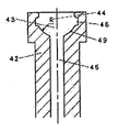
- FIG. 10 is a cross-sectional view of the nozzle receiver 42 that holds the nozzle 35 according to the present invention.
- the nozzle receiver 42 includes a concave hemispherical seal portion 43 that receives the hemispherical seal portion 37 of the nozzle 35, and a gas passage 45 is formed through the center.
- the concave hemispherical seal portion 43 is provided with an O-ring groove 46 for holding the nozzle 35.
- the spherical radius R40 of the concave hemispherical seal portion 43 and the spherical radius R44 of the nozzle receiving concave hemispherical seal portion 43 are formed to have the same length.
- the nozzle 35 can be rotated on the concave hemispherical seal portion 43 of the nozzle receiver 42 with the rotating sphere center 51 as a fulcrum.
- the widths of the O-ring grooves 39 and 46 provided in the nozzle 35 and the nozzle receiver 42 be wider than the diameter of the O-ring 47 in accordance with the inclination angle of the nozzle 35.
- FIG. 1 is a cross-sectional view of an O-ring 47 that is held by a nozzle receiver 42 while keeping the nozzle 35 movable.
- FIG. 12 is a cross-sectional view of the nozzle unit 52 of the present invention formed using the nozzle 35, the nozzle receiver 42, and the O-ring 47.
- the seal portion contact surfaces 48 and 49 are in close contact with each other, and gas leakage can be prevented. Since the nozzle 35 is easily removed from the nozzle receiver 42, it has good maintainability and can be replaced with a nozzle that fits the ventilation openings of various breathing filters.
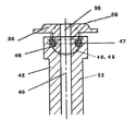
- FIG. 13 is a cross-sectional view of the connecting portion when the nozzle unit 52 of the present invention is attached to the purge device 16 and the FOUP 11 is purged with N 2 gas.
- the ventilation opening 5 of the breathing filter unit 1 is inclined by the bottom portion 12 of the FOUP 11 inclined by washing and drying. Due to the rotation of the nozzle 35, the nozzle tip portion 36 is in close contact with the inclined ventilation opening 5, so that the outgas 50 from the O-ring 47 is blocked by the seal portion contact surfaces 48 and 49. Further, the outgas 50 is discharged outside without being mixed into the gas passage 38.
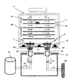
- FIG. 14 shows the N2 gas purge performance test status of the FOUP 11 by the purge device 16 equipped with the nozzle unit 52 of the present invention.
- An oxygen concentration meter 54 is installed on the wafer 14 in the FOUP 1. Changes in the oxygen concentration in the FOUP 11 due to purging are measured and converted into changes in the concentration of N 2 gas.
- FIG. 15 shows a comparison of the purge time when the conventional nozzle is used and when the nozzle unit of the present invention is used.
- the purge time is greatly shortened as a result of completely preventing gas leakage from the connecting portion between the breathing filter unit of the FOUP 1 and the nozzle unit 52. I was able to.
Landscapes
- Container, Conveyance, Adherence, Positioning, Of Wafer (AREA)
- Packaging Frangible Articles (AREA)
Abstract
半導体製造ラインにおいて、FOUP内へN2ガスを供給して、N2ガスパージを十分に行うことができ、且つパージ時間も短くすることができるノズルユニットを提供する。ノズルユニットは上部にブリージングフィルターユニットの通気開口に密着するノズル先端部(36)、下部に半球面シール部(37)を備えると共に、上部と下部をガス通路(38)が開通した構造のノズル(35)と、上部に前記ノズル(35)の半球面シール部(37)を受けて保持するための凹型半球面シール部(43)を備え且つ中心にガス通路(45)を備えたノズル受け(42)とを具備する。更に、前記ノズル(35)の可動性を維持したまま、該ノズル(35)をノズル受け(42)に保持すべく、ノズル(35)とノズル受け(42)にOリング溝(46)および保持用Oリング(47)をそれぞれ設ける。
Description
本発明は、ミニ・エンバイ口ンメント方式の半導体クリーンルームで使用される半導体ウエハ収納容器(以下、「FOUP」という)を、N2ガスパージするパージ装置においてN2ガス供給ノズルおよび排気ノズルを備えたN2ガスパージ装置におけるノズルユニットに関するものである。
現在、半導体製造クリーンルームでは、ウエハをFOUPに収納し、外気に触れずに半導体製造装置間を搬送・ハンドリングするミニ・工ンバイラメント方式が一般的となっている。
現在、半導体回路の微細化が進み、先端の半導体ICは32nmのテザインルールで生産されており、22nmでの生産も迫ってきている。その結果、半導体プ口セス環境への要求も一段と厳しくなり、プ口セス工程によっては、ウエハを収納したFOUP内の水分、ケミ力ルガスを完全に除去することが必要になってきている。
FOUPには、輸送中に大気圧が変化した場合、内部の圧力と外気圧力を均一にして、FOUPの膨張、収縮を防ぐために、FOUPの底板にブリージングフィルターユニットが備えられている。そして、前記ブリージングフィルターユニットには、ブリージングフィルターが取り付けられている。該ブリージングフィルターは、FOUP内部と外部との空気の出入り時に、外部からFOUP内に塵が侵入するのを防ぐためのものである。
そして現在、FOUP内のウエハ面への水分、ケミ力ルガスの付着が歩留まり低下を引き起こす工程では、N2ガスパージが採用されている。これにより、高純度のN2ガスでFOUP内の残留ガスを追い出し、N2ガスを満たすことにより、ウエハ表面を水分またはケミ力ルガスによる汚染から保護する。
前記N2ガスパージが採用されるようになってからは、N2ガスパージ用FOUPの底板に設置されたブリージングフィルターユニットには、N2ガス供給用ブリージングフィルターユニットと、排気用ブリージングフィルターユニットとがそれぞれ1種類ずつ装備されている。N2ガス供給用ブリージングフィルターユニットは、FOUPへのN2ガスの供給時のみ開放するバルブを備えている。排気用ブリージングフィルターユニットは、FOUP内の残留ガスをFOUP外部へ排気する時のみ開放するバルブを備えている。FOUP内をN2ガスに置換後は、前記のそれぞれのバルブは閉鎖され、FOUP内のN2ガスが外部へ漏れなぃようにシールされている。
発明が解決しようとする課題
前記N2ガスパージ用FOUPの底板には、FOUPメー力により、色々なタイプのブリージングフィルターユニットが装備されている。いずれのメー力のブリージングフィルターユニットも、N2ガス供給側のブリージングフィルターユニットは、筒状筐体の上部に上端開口部を、底部にN2ガス供給側通気開口を備えている。そして、上端開口部はフィルターを備え、N2ガス供給側通気開口はブリージングフィルターユニット内へのN2ガス供給時のみ開放になるシャターを備える。さらに、残留ガス排気側のブリージングフィルターユニットは、筒状筐体の上部に上端開口部を、底部に残留ガス排気側通気開口を備えている。そして、上端開口部はフィルターを備え、残留ガス排気側通気開口はブリージングフィルターユニット内の残留ガスが排出されるときのみ開放になるシャッターを備えている。
前記N2ガスパージ装置のFOUP搭載面には、FOUP位置決め用キネマピンが3セットと、FOUP内へN2ガスを供給するN2ガス供給ノズルおよびF0UP内の残留ガスの排気用ノズルの2種類が設置されている。半導体ウエハが収納されたFOUPをN2ガスパージする場合、前記FOUPを前記N2ガスパージ装置に搭載する。このとき、前記FOUPは前記キネマピンによって位置決めされる。また、前記F0UP底部のブリージングユニットのN2ガス供給側通気開ロは前記N2ガス供給ノズルと連結される。そして、残留ガス排気側通気開口は排気ノズルと連結される。
N2ガスパージ装置のN2ガス供給ノズルから供給されるN2ガスは、前記FOUP底部のブリージングフィルターユニットのN2ガス供給側通気開口より、半導体ウエハが収納されたFOUP内部に入る。FOUP内部の残留ガスは、前記F0UP底部のブリージングユニットの残留ガス排気側通気開口に連結されたN2パージ装置の排気用ノズルを通り、外部へ吸引排出される。
半導体製造ラインでは、FOUPは定期的に温水洗浄・乾燥される。その際、前記FOUPは樹脂製のため少しずつ変形して行く。前記FOUPがパージ装置上に搭載され、3セットのキネマピンで、FOUPを定位置に保持しても、何回も洗浄・乾燥を繰り返したFOUPは歪んでしまい、FOUPの底部も水平が保てなくなる。更に、前記ブリージングフィルターユニットは消耗品として交換される。従って、各社のブリージングフィルターユニットのFOUP底部への取り付けは簡単に出来るようになっているが、精度良く水平を保てるような構造になっていない。その結果、N2パージ装置にFOUPが搭載された場合、N2ガス供給ノズルとN2ガス供給側通気開口、残留ガス排気ノズルと残留ガス排気側通気開口の間に、それぞれの通気開ロの傾斜が原因で隙間が発生する。その結果、それぞれの隙間からN2ガスおよび残留ガスが漏れてしまい、FOUP内のN2ガスパージが不安定になり、パージ時間も長くなるという課題があった。
また、半導体の微細化に伴い半導体プ口セスからのFOUP仕様、ブリージングフィルター仕様への要求も頻繁に変わっている。結果として、ブリージングフィルターユニット1は、同一メー力でも仕様が異なるものもあり、N2ガス供給側通気開口、残留ガス排気側通気開口の形状も各種存在する。
そのため、N2ガスパージ装置では、新たなブリージングフィルターと連結できるN2ガス供給ノズルおよび排気ノズルを新たに準備しなくてはならないという課題があった。
更に、前記従来のN2ガスパージ装置では、連結部からのN2ガスの漏れを防ぐために、N2ガス供給ノズルの先端および排気ノズルの先端、またはN2ガス供給側通気開口部および残留ガス排気側通気開口部に弾力性のあるゴム系材料を使用しているものもある。この場合、塵、アウトガスが発生するため、半導体ウエハプ口セスに悪影響を及ぼすという課題があった。
本発明は、半導体製造ラインにおいて、FOUP(半導体ウエハ収納容器)内部をN2ガスで充満させるN2ガス供給ノズルと排気ノズルを備えたN2ガスパージ装置の、各ノズルに適用するノズルユニットである。FOUPの底部にはブリージングフィルターユニットが設けられ、ブリージングフィルターユニットにはN2ガス供給側通気開口と残留ガス排気側通気開口が設けられている。FOUPを前記N2ガスパージ装置に搭載したとき、N2ガス供給側通気開口とN2ガス供給ノズルとが連結されると共に、残留ガス排気側通気開口と排気ノズルとが連結される。N2ガス供給ノズルによりFOUP内部にN2ガスを供給し、排気ノズルによりFOUP内部の残留ガスを排出してFOUP内部をN2ガスで充満させる。ノズルユニットは、ノズルとノズル受けとOリングとを具備する。ノズルは上部にブリージングフィルターユニットの通気開口に密着するノズル先端部、下部に半球面シール部を備えると共に、上部と下部をガス通路が貫通した構造を有する。ノズル受けは、上部に前記ノズルの半球面シール部を受けて保持するための凹型半球面シール部を備え、且つ中心にガス通路を備える。更に、ノズルの可動性を維持したまま、ノズルをノズル受けに保持するために、ノズルとノズル受けのそれぞれに0リング溝が設けられている。また、ノズルとノズル受けに保持用Oリングが設けられている。かかる手段を採用することにより、上記課題を解決した。
本発明に係るノズルユニットは、ノズルとノズル受けとOリングとを具備する。ノズルは上部にブリージングフィルターユニットの通気開口に密着するノズル先端部、下部に半球面シール部を備えると共に、上部と下部をガス通路が貫通した構造を有する。ノズル受けは、上部に前記ノズルの半球面シール部を受けて保持するための凹型半球面シール部を備え、且つ中心にガス通路を備える。更に、ノズルの可動性を維持したまま、ノズルをノズル受けに保持するために、ノズルとノズル受けのそれぞれに0リング溝が設けられている。また、ノズルとノズル受けに保持用Oリングが設けられている。したがって、洗浄・乾燥によりFOUPの底部が傾斜し、その結果、ブリージングフィルターユニットの通気開口が傾斜していても、前記ノズルの回転により、ノズル先端部が傾斜した通気開口に密着する。したがって、Oリングからのアウトガスはシール部接触面で遮断される。また、アウトガスはガス通路には混入されず外部に放出され、完全にガスパージができる。
以下、本発明の実施例を図に基づいて詳細に説明する。図1は従来汎用されているFOUPの斜視図である。図2は同FOUPとN2ガス供給側ブリージングフィルターユニットの縦断面図である。図3は同残留ガス排気側ブリージングフィルターユニットの縦断面図である。図1~図3に示すように、FOUP11の底部12には、N2ガス供給側ブリージングフィルターユニット1と残留ガス排気側ブリージングフィルターユニット6が取り付けられている。N2ガス供給側ブリージングフィルターユニット1は、上端開ロ部2、フイルター3、N2ガス供給側通気開口5を備え、内部にはN2ガス供給時のみ開放するN2ガス供給側シャッター4を備えている。また、排気側ブリージングフィルターユニット6は上端開口部7、フィルター8、残留ガス排気側通気開ロ10を備え、内部には残留ガス排気時のみ開放する残留ガス排気側シャッター9を備えて形成されている。
図4は、従来のノズルを装備したN2ガスパージ装置16の斜視図である。前記N2ガスパージ装置16のFOUP搭載部17には、N2ガス供給側ノズル19と残留ガス排気側ノズル20が装備されると共に、キネマピン18が3セット突設されている。キネマピン18は、前記FOUP11の搭載時、該FOUP11の位置決めを行う。更に、前記N2ガスパージ装置16には、N2ガス25の供給用のN2ガス供給口21と残留ガス26の排気用の残留ガス排気口22とが設けられている。また、前記パージ裝置16の内部の電磁バルブ(図示せず)を操作するための、電磁バルブ制御盤23がケーブル24でパージ装置16に接続されている。
図5は、従来のノズルを装備したパージ装置16のFOUP搭載部17上にFOUP11を搭載し、N2ガスパージを行うときのN2ガス25および残留ガス26の流れを示す断面図である。半導体ウエハ14が収納されたFOUP11をN2ガスパージ装置16上に搭載する。このとき、FOUP11はキネマビン18によって位置決めされる。FOUP11底部のブリージングユニット1,6のN2ガス供給側通気開ロ5はN2ガス供給ノズル19と連結される。そして、残留ガス排気側通気開口10は排気ノズル20と連結される。
N2ガス25は、N2ガス供給源27よりN2ガス供給口21を経て、前記パージ装置16のN2ガス供給ノズル19から供給される。そして、N2ガス25は、FOUP11底部のN2ガス供給側ブリージングフィルターユニット1のN2ガス供給側通気開口5より、半導体ウエハ14が収納されたFOUP11内部に入る。FOUP11内部の残留ガス26は、FOUP11底部の残留ガス排気側ブリージングフィルターユニット6の残留ガス排気側通気開口10に連結されたパージ装置16の排気用ノズル20、残留ガス排気口22を通り、排気ダクト28から外部へ吸引排出される。その結果、FOUP11内はN2ガス25で充満される。
図6は、従来のパージ装置16におけるN2ガス供給ノズル19とN2ガス供給側ブリージングフィルターユニット1のN2ガス供給側通気開口5との連結状態を示す断面図である。
一般に、半導体製造ラインでは、FOUP1は定期的に温水洗浄・乾燥される。FOUP1は樹脂製のため少しずつ変形して行く。FOUP11がパージ装置16上に搭載され、キネマピン18でF0UP11を定位置に保つても、何回も洗浄・乾燥を繰り返したFOUP11は歪んでしまい、FOUP11の底部12も水平が保てなくなる。更に、N2ガス供給側ブリージングフィルターユニット1は消耗品として交換されるため、各社のN2ガス供給側ブリージングフィルターユニット1のFOUP底部12への取り付け方法は簡単さが優先されてしまう。そのため、精度良く水平が維持できなくなり、N2ガス供給ノズル19とN2ガス供給側通気開口5との間に傾斜31(θ)が原因で隙間30が発生する。その結果、N2ガスパージ時には、前記隙間30からN2ガスが漏れてしまうことになる。
また、残留ガス排気側の連結部でも、前記N2ガス供給側と同様の原因による隙間が発生するため、F0UP11内の残留ガス26の吸引・排出が十分にされなくなる。その結果、FOUP11のN2ガスパージが十分に行われず、パージ時間も長くなるという問題点があった。
図7、8に、従来のN2ガス供給側の連結部での、前記問題点に対する対策例を示す。前記対策例は、残留ガス排気側の連結部でも同一であるので、残留ガス排気側の連結部の説明を省略する。図7は、従来の一般的な対策例を示す断面図である。図に示すように、N2ガス供給側通気開ロ5またはN2ガス供給ノズル先端29を、弾力性のある材質53にする方法である。この方法であると、シール性はある程度確保できるが、弾力性のある材質53からのアウトガスが多くなる。このため、先端半導体製造ラインでは、使用できないという課題があった。
また、図8はN2ガス供給側通気開口5の傾斜に従って、N2ガス供給ノズル19が傾斜するようにN2ガス供給ノズル19をバネ33で支持したものである。N2ガス供給側通気開口5が傾斜すると、該N2ガス供給側通気開口5とN2ガス供給側通気開口5の中心のずれD34が発生する。このため、FOUP1とN2ガスパージ装置16を連結するには、該FOUP11とN2パージ装置16に歪が伴うという課題があった。
図9,10,11,12に、本発明に係るノズルユニットおよびその構成部品を示す。本発明に係るノズルユニット52は、ノズル35とノズル受け42とOリング47とを具備する。図9は、ノズル35の断面図である。前記ノズル35は、ノズル先端部36と半球面シール部37とを備えると共に、中央にNガス通路38を貫通して形成されている。ノズル先端部36は各仕様のブリージングフィルターのN2ガス供給側通気開口5および残留ガス排気側通気開口10に合わせた形状を有する。半球面シール部37はノズル先端部36の反対側にある。更に、前記ノズル35の可動性、シール性を保ちながら、該ノズル35をノズル受け42に保持するため、Oリング溝39が半球面シール部37を取り囲むように設けられている。
ブリージングフィルターユニット1,6を構成するN2ガス供給側通気開口5および残留ガス排気側通気開口10の傾斜31(θ)に合わせ、前記ノズル先端部36がスムーズに傾斜し、それぞれの中心がずれないようにノズル35を設計する必要がある。そのためには、該ノズル35の長さL(ノズル先端部からノズル半球面シール部までの長さ)が、ノズル半球面シール部37の球面半径R40に対して、L≒2Rとなるようにすることが好ましい。
図10は、本発明に係るノズル35を保持するノズル受け42の断面図である。前記ノズル受け42は、ノズル35の半球面シール部37を受ける凹型半球面シール部43を備え、中央にはガス通路45が貫通して形成されている。また、前記凹型半球面シール部43には、ノズル35を保持するためのOリング溝46が周設されている。前記凹型半球面シール部43の球面半径R40と、ノズル受け凹型半球面シール部43の球面半径R44は同一長さに形成される。更に、ノズル35がノズル受け42の凹型半球面シール部43上を回転球中心51を支点にして回転できるようにする。そのためには、ノズル35とノズル受け42に設けられたOリング溝39,46の幅は、前記ノズル35の傾斜角度に合わせ、Oリング47の直径より幅広くすることが推奨される。
図1は、前記ノズル35の可動性を保ちながらノズル受け42に保持するOリング47の断面図である。
図12は、ノズル35、ノズル受け42、およびOリング47を用いて形成された本発明ノズルユニット52の断面図である。ノズル35がノズル受け42に嵌合されると、それぞれシール部接触面48,49が密に接触し、ガスの漏れを防ぐことができる。前記ノズル35は、ノズル受け42から取り外し司能なため、保守性も良く、各種のブリージングフィルターの通気開口に合うノズルと交換することができる。
図13は、本発明ノズルユニット52をパージ装置16に装着し、FOUP11をN2ガスパージする時の連結部の断面図である。洗浄・乾燥により傾斜したFOUP11の底部12により、ブリージングフィルターユニット1の通気開ロ5は傾斜している。ノズル35の回転により、ノズル先端部36は傾斜した通気開口5に密着しているため、Oリング47からのアウトガス50はシール部接触面48,49で遮断される。また、アウトガス50は、ガス通路38には混入されず外部に放出される。
図14は、本発明ノズルユニット52を装着したパージ装置16によるFOUP11をN2ガスパージ性能試験状況を示す。FOUP1内のウエハ14の上に酸素濃度計54が設置されている。パージによるFOUP11内の酸素濃度の変化を測定し、N2ガスの濃度変化に換算している。
図15は、従来のノズルを使用した時と、本発明ノズルユニットを使用した時のパージ時間の比較を示す。本発明のノズルユニットを使用することにより、FOUP1のブリージングフィルターユニットとノズルユニット52との連結部からのガスの漏れが、完全に防げた結果、パージ時間が大幅に短縮されることを立証することができた。
本明細書および図面で用いた符号を以下にまとめて示す。
1 N2ガス供給側ブリージングフィルターユニット
2 N2ガス供給側上部開口部
3 N2ガス供給側フィルター
4 N2ガス供給側シャッター
5 N2ガス供給側通気開口
6 残瑠ガス排気側ブリージングフィルターユニット
7 残瑠ガス排気側上部開口部8残瑠ガス排気側フィルター
9 残瑠ガス排気側シャッター
10 残瑠ガス排気側通気開ロ
11 FOUP12底部
13 ドア
14 ウエハ
15 ウエハ間隙間
16 N2ガスパージ装置17FOUP搭載部
18 キネマピン
19 従来のN2ガス供給側ノズル20従来の残瑠ガス排気側ノズル
21 N2ガス供給口
22 残瑠ガス排気口23電磁バルブ制御盤
24 ケーブル25N2ガス
26 残瑠ガス
27 N2ガス供給源
28 排気ダクト
29 従来のN2ガス供給側ノズル先端
30 隙間
31 傾斜角
32 漏洩N2ガス33バネ
34 中心のずれ
35 本発明のノズル
36 本発明のノズル先端部
37 本発明のノズル半球面シール部38本発明のノズルガス通路
39 本発明のノズルOリング溝
40 本発明のノズルシール部球面半径
41 本発明のノズル長さ
42 本発明のノズル受け
43 本発明のノズル受け凹型半球面シール部
44 本発明のノズル受け凹型シール部球面半径
45 本発明のノズル受けガス通路
46 本発明のノズル受けOリング溝
47 Oリング断面
48 本発明のノズル半球面シール部接触面
49 本発明のノズル受け凹型半球面シール部接触面
50 Oリングからのアウトガス51本発明のノズル回転中心
52 本発明のノズルユニット53シールゴム
54 酸素濃度計
Claims (2)
- 半導体製造ラインにおいて、FOUP(半導体ウエハ収納容器)内部をN2ガスで充満させるN2ガス供給ノズルと排気ノズルを備えたN2ガスパージ装置の、該N2ガス供給ノズルと該排気ノズルに適用するノズルユニットであって、
前記FOUPの底部にはブリージングフィルターユニットが設けられ、
該ブリージングフィルターユニットにはN2ガス供給側通気開口と残留ガス排気側通気開口が設けられ、
前記FOUPを前記N2ガスパージ装置に搭載したとき、前記N2ガス供給側通気開口と前記N2ガス供給ノズルとが連結されると共に、前記残留ガス排気側通気開口と前記排気ノズルとが連結され、
前記N2ガス供給ノズルによりFOUP内部にN2ガスを供給し、前記排気ノズルにより前記FOUP内部の残留ガスを排出して該FOUP内部をN2ガスで充満させるものであり、
前記ノズルユニットは、
上部にブリージングフィルターユニットの通気開口に密着するノズル先端部、下部に半球面シール部を備えると共に、上部と下部をガス通路が貫通した構造のノズルと、
上部に前記ノズルの半球面シール部を受けて保持するための凹型半球面シール部を備え、且つ中心にガス通路を備えたノズル受けと、
を具備し、
前記ノズルの可動性を維持したまま、該ノズルを前記ノズル受けに保持するために、該ノズルと該ノズル受けのそれぞれに0リング溝が設けられると共に、保持用Oリングを具備することを特徴とするノズルユニット。
- 前記ノズルの下部の半球面シール部と、前記ノズル受けの凹型半球面シール部のそれぞれの半球面が同一球半径Rを有し、該ノズルの長さLと球半径Rとの関係は2R≒Lであり、該ノズルと該ノズル受けに設けられたOリング溝の幅は、該ノズル受けの凹型半球面シール部上をノズルが半球中心を支点に回転できるように、ノズルの傾き角度にあわせ、Oリングの直径より幅広くすることを特徴とする、請求項1に記載のノズルユニット。
Applications Claiming Priority (2)
| Application Number | Priority Date | Filing Date | Title |
|---|---|---|---|
| JP2011-040792 | 2011-02-08 | ||
| JP2011040792A JP5815959B2 (ja) | 2011-02-08 | 2011-02-08 | N2ガスパージ装置におけるノズルユニット |
Publications (1)
| Publication Number | Publication Date |
|---|---|
| WO2012108418A1 true WO2012108418A1 (ja) | 2012-08-16 |
Family
ID=46638631
Family Applications (1)
| Application Number | Title | Priority Date | Filing Date |
|---|---|---|---|
| PCT/JP2012/052715 Ceased WO2012108418A1 (ja) | 2011-02-08 | 2012-02-07 | N2ガスパージ装置におけるノズルユニット |
Country Status (2)
| Country | Link |
|---|---|
| JP (1) | JP5815959B2 (ja) |
| WO (1) | WO2012108418A1 (ja) |
Cited By (4)
| Publication number | Priority date | Publication date | Assignee | Title |
|---|---|---|---|---|
| CN105474380A (zh) * | 2013-08-20 | 2016-04-06 | 村田机械株式会社 | 气体清洗装置及气体清洗方法 |
| FR3058562A1 (fr) * | 2016-11-07 | 2018-05-11 | Pfeiffer Vacuum | Dispositif et procede de controle de l'etancheite d'une enceinte de transport pour le convoyage et le stockage atmospherique de substrats semi-conducteurs |
| CN108689066A (zh) * | 2017-03-29 | 2018-10-23 | 株式会社大福 | 收纳架 |
| US10453723B2 (en) | 2014-11-12 | 2019-10-22 | Miraial Co., Ltd. | Gas purge filter |
Families Citing this family (11)
| Publication number | Priority date | Publication date | Assignee | Title |
|---|---|---|---|---|
| JP5887719B2 (ja) | 2011-05-31 | 2016-03-16 | シンフォニアテクノロジー株式会社 | パージ装置、ロードポート、ボトムパージノズル本体、ボトムパージユニット |
| JP6323245B2 (ja) * | 2014-08-08 | 2018-05-16 | Tdk株式会社 | ガスパージユニット、ロードポート装置およびパージ対象容器の設置台 |
| JP5776828B1 (ja) | 2014-08-08 | 2015-09-09 | Tdk株式会社 | ガスパージユニット、ロードポート装置およびパージ対象容器の設置台 |
| JP6565336B2 (ja) | 2015-05-28 | 2019-08-28 | Tdk株式会社 | ガスパージユニット、ロードポート装置およびパージ対象容器の設置台 |
| JP6600853B2 (ja) * | 2016-01-15 | 2019-11-06 | 信越ポリマー株式会社 | 樹脂部材の製造方法、筐体部材の製造方法及び基板収納容器の製造方法 |
| KR101776486B1 (ko) | 2016-04-07 | 2017-09-08 | 현대자동차주식회사 | 차량의 배기정화장치 및 그 제어방법 |
| JP7125000B2 (ja) | 2018-03-13 | 2022-08-24 | 信越ポリマー株式会社 | 基板収納容器 |
| JP6519897B2 (ja) * | 2018-04-10 | 2019-05-29 | シンフォニアテクノロジー株式会社 | パージノズルユニット、ロードポート |
| JP6882698B2 (ja) * | 2019-04-24 | 2021-06-02 | シンフォニアテクノロジー株式会社 | パージノズルユニット、ロードポート |
| JP7741645B2 (ja) | 2020-05-26 | 2025-09-18 | エーエスエム・アイピー・ホールディング・ベー・フェー | パージノズルアセンブリおよびパージノズルアセンブリを備える半導体処理アセンブリ |
| CN121866889A (zh) * | 2023-07-21 | 2026-04-14 | 恩特格里斯公司 | 将气体分配到容器的方法及装置 |
Citations (4)
| Publication number | Priority date | Publication date | Assignee | Title |
|---|---|---|---|---|
| JPH05318368A (ja) * | 1992-05-18 | 1993-12-03 | Tokyo Electron Yamanashi Kk | 吸着搬送装置 |
| WO2004100254A1 (ja) * | 2003-05-06 | 2004-11-18 | Olympus Corporation | 基板吸着装置 |
| JP2007022758A (ja) * | 2005-07-15 | 2007-02-01 | Ckd Corp | 板状ワークの移載装置 |
| JP2010182747A (ja) * | 2009-02-03 | 2010-08-19 | Dan Takuma:Kk | 保管システムおよび保管方法 |
-
2011
- 2011-02-08 JP JP2011040792A patent/JP5815959B2/ja active Active
-
2012
- 2012-02-07 WO PCT/JP2012/052715 patent/WO2012108418A1/ja not_active Ceased
Patent Citations (4)
| Publication number | Priority date | Publication date | Assignee | Title |
|---|---|---|---|---|
| JPH05318368A (ja) * | 1992-05-18 | 1993-12-03 | Tokyo Electron Yamanashi Kk | 吸着搬送装置 |
| WO2004100254A1 (ja) * | 2003-05-06 | 2004-11-18 | Olympus Corporation | 基板吸着装置 |
| JP2007022758A (ja) * | 2005-07-15 | 2007-02-01 | Ckd Corp | 板状ワークの移載装置 |
| JP2010182747A (ja) * | 2009-02-03 | 2010-08-19 | Dan Takuma:Kk | 保管システムおよび保管方法 |
Cited By (12)
| Publication number | Priority date | Publication date | Assignee | Title |
|---|---|---|---|---|
| CN105474380A (zh) * | 2013-08-20 | 2016-04-06 | 村田机械株式会社 | 气体清洗装置及气体清洗方法 |
| CN105474380B (zh) * | 2013-08-20 | 2017-10-31 | 村田机械株式会社 | 气体清洗装置及气体清洗方法 |
| US10453723B2 (en) | 2014-11-12 | 2019-10-22 | Miraial Co., Ltd. | Gas purge filter |
| TWI686232B (zh) * | 2014-11-12 | 2020-03-01 | 日商未來兒股份有限公司 | 氣體淨化用過濾器 |
| FR3058562A1 (fr) * | 2016-11-07 | 2018-05-11 | Pfeiffer Vacuum | Dispositif et procede de controle de l'etancheite d'une enceinte de transport pour le convoyage et le stockage atmospherique de substrats semi-conducteurs |
| WO2018083312A1 (fr) * | 2016-11-07 | 2018-05-11 | Pfeiffer Vacuum | Dispositif et procédé de contrôle de l'étanchéité d'une enceinte de transport pour le convoyage et le stockage atmosphérique de substrats semi-conducteurs |
| CN109937473A (zh) * | 2016-11-07 | 2019-06-25 | 普发真空公司 | 控制用于半导体基板的传送和大气存储的运送盒的密封性的装置和方法 |
| JP2019533907A (ja) * | 2016-11-07 | 2019-11-21 | ファイファー バキユーム | 半導体基板を搬送および大気圧下で保管するための輸送用密閉容器の気密性を制御する装置および方法 |
| TWI753040B (zh) * | 2016-11-07 | 2022-01-21 | 法商普發真空公司 | 用於控制針對半導體基板之輸送及大氣儲存的傳輸外殼之緊密性的裝置及方法 |
| JP7041144B2 (ja) | 2016-11-07 | 2022-03-23 | ファイファー バキユーム | 半導体基板を搬送および大気圧下で保管するための輸送用密閉容器の気密性を制御する装置および方法 |
| US11430681B2 (en) | 2016-11-07 | 2022-08-30 | Pfeiffer Vacuum | Device and method for controlling the tightness of a transport enclosure for the conveyance and atmospheric storage of semiconductor substrates |
| CN108689066A (zh) * | 2017-03-29 | 2018-10-23 | 株式会社大福 | 收纳架 |
Also Published As
| Publication number | Publication date |
|---|---|
| JP2012164948A (ja) | 2012-08-30 |
| JP5815959B2 (ja) | 2015-11-17 |
Similar Documents
| Publication | Publication Date | Title |
|---|---|---|
| WO2012108418A1 (ja) | N2ガスパージ装置におけるノズルユニット | |
| US10930537B2 (en) | Door opening/closing system, and load port equipped with door opening/closing system | |
| US10947063B2 (en) | Load port | |
| JP5925474B2 (ja) | ウエハ処理装置 | |
| US20090029046A1 (en) | Substrate processing apparatus, method for processing substrate, and storage medium | |
| TW202102416A (zh) | 基板容器系統 | |
| US9598767B2 (en) | Gas processing apparatus | |
| TW201830562A (zh) | 基板處理裝置 | |
| WO2012014940A1 (ja) | N2ガスパージ用ブリージングフィルターユニットおよび該フィルターユニットを搭載した半導体ウエハ収納容器をn2ガスパージするパージ装置 | |
| JP7041144B2 (ja) | 半導体基板を搬送および大気圧下で保管するための輸送用密閉容器の気密性を制御する装置および方法 | |
| CN111799200A (zh) | 输送装置、工件处理装置、输送装置的控制方法、存储程序的记录介质 | |
| TWI773536B (zh) | 基板容器系統 | |
| TW201924788A (zh) | 計量及檢驗系統內之局部清洗 | |
| JP2024137664A (ja) | 気体弁蓋および其れを応用する基板キャリア | |
| KR102101413B1 (ko) | 파티클 측정장치 | |
| JP2000100907A (ja) | 基板処理装置 | |
| JP6323245B2 (ja) | ガスパージユニット、ロードポート装置およびパージ対象容器の設置台 | |
| CN116195035A (zh) | 基板处理装置和声音传感器用防水装置 | |
| US20250091024A1 (en) | Opening/closing mechanism, exhaust switching mechanism, and substrate processing device | |
| TWM584983U (zh) | 充氣系統 | |
| TW202548415A (zh) | 充氣盤結構 | |
| TW202601272A (zh) | 充氣頭及含充氣頭之充氣模組 | |
| KR102113276B1 (ko) | 가스공급용 노즐패드 및 이를 구비한 웨이퍼 용기의 가스공급장치 | |
| KR20250069560A (ko) | 반도체 기판을 운반하는 캐리어의 기상 오염을 측정하는 측정 장치 및 관련 측정 방법 | |
| KR20050026767A (ko) | 반도체 설비의 배기장치 |
Legal Events
| Date | Code | Title | Description |
|---|---|---|---|
| 121 | Ep: the epo has been informed by wipo that ep was designated in this application |
Ref document number: 12744614 Country of ref document: EP Kind code of ref document: A1 |
|
| NENP | Non-entry into the national phase |
Ref country code: DE |
|
| 122 | Ep: pct application non-entry in european phase |
Ref document number: 12744614 Country of ref document: EP Kind code of ref document: A1 |