WO2012108533A1 - 発光素子用基板の製造方法および発光素子用基板 - Google Patents
発光素子用基板の製造方法および発光素子用基板 Download PDFInfo
- Publication number
- WO2012108533A1 WO2012108533A1 PCT/JP2012/053163 JP2012053163W WO2012108533A1 WO 2012108533 A1 WO2012108533 A1 WO 2012108533A1 JP 2012053163 W JP2012053163 W JP 2012053163W WO 2012108533 A1 WO2012108533 A1 WO 2012108533A1
- Authority
- WO
- WIPO (PCT)
- Prior art keywords
- frame
- green sheet
- substrate
- laminating
- laminate
- Prior art date
- Legal status (The legal status is an assumption and is not a legal conclusion. Google has not performed a legal analysis and makes no representation as to the accuracy of the status listed.)
- Ceased
Links
Images


Classifications
-
- H—ELECTRICITY
- H10—SEMICONDUCTOR DEVICES; ELECTRIC SOLID-STATE DEVICES NOT OTHERWISE PROVIDED FOR
- H10H—INORGANIC LIGHT-EMITTING SEMICONDUCTOR DEVICES HAVING POTENTIAL BARRIERS
- H10H20/00—Individual inorganic light-emitting semiconductor devices having potential barriers, e.g. light-emitting diodes [LED]
- H10H20/80—Constructional details
- H10H20/85—Packages
- H10H20/855—Optical field-shaping means, e.g. lenses
- H10H20/856—Reflecting means
-
- H—ELECTRICITY
- H10—SEMICONDUCTOR DEVICES; ELECTRIC SOLID-STATE DEVICES NOT OTHERWISE PROVIDED FOR
- H10H—INORGANIC LIGHT-EMITTING SEMICONDUCTOR DEVICES HAVING POTENTIAL BARRIERS
- H10H20/00—Individual inorganic light-emitting semiconductor devices having potential barriers, e.g. light-emitting diodes [LED]
- H10H20/80—Constructional details
- H10H20/85—Packages
- H10H20/8506—Containers
-
- H—ELECTRICITY
- H10—SEMICONDUCTOR DEVICES; ELECTRIC SOLID-STATE DEVICES NOT OTHERWISE PROVIDED FOR
- H10W—GENERIC PACKAGES, INTERCONNECTIONS, CONNECTORS OR OTHER CONSTRUCTIONAL DETAILS OF DEVICES COVERED BY CLASS H10
- H10W90/00—Package configurations
- H10W90/701—Package configurations characterised by the relative positions of pads or connectors relative to package parts
- H10W90/751—Package configurations characterised by the relative positions of pads or connectors relative to package parts of bond wires
- H10W90/754—Package configurations characterised by the relative positions of pads or connectors relative to package parts of bond wires between a chip and a stacked insulating package substrate, interposer or RDL
Definitions
- the present invention relates to a method for manufacturing a light emitting element substrate and a light emitting element substrate, and more particularly to a method for manufacturing a ceramic light emitting element substrate having a tapered side cavity and a ceramic light emitting element substrate.
- a light emitting element substrate (hereinafter also simply referred to as an element substrate) for mounting a light emitting element such as a light emitting diode element has a structure in which a wiring conductor layer is disposed on or inside an insulating substrate.
- a typical example of the substrate for a light emitting element is a ceramic insulating substrate made of ceramics, and an example thereof is an insulating substrate made of alumina ceramics (hereinafter referred to as an alumina substrate).
- a cavity for accommodating the light emitting element is formed on the top of the alumina substrate, and a plurality of wiring conductor layers made of a refractory metal such as tungsten or molybdenum are disposed on the surface and inside of the alumina substrate. There is a configuration that is electrically connected to a light emitting element accommodated in the bottom surface of the cavity.
- low-temperature co-fired ceramics composed of low-melting-point glass and ceramics can be used as insulating substrates because low-temperature firing, low dielectric constant, and high electrical conductivity copper and silver wiring are possible.
- a glass ceramic substrate called “Low Temperature Co-fired Ceramics” (hereinafter referred to as LTCC) has been proposed.
- LTCC Low Temperature Co-fired Ceramics
- the above ceramic insulating substrate and glass ceramic substrate are collectively referred to as a ceramic substrate.
- the characteristics required for the substrate for the light emitting element include weather resistance, light extraction efficiency, thermal conductivity, and the like.
- a metal layer such as a silver reflection film has been conventionally applied to the surface of the cavity for housing the light emitting element, and the cavity In general, the side surfaces are tapered toward the top.
- the ceramic substrate having a cavity is usually produced by joining a frame having an opening on a flat substrate.
- a method of forming a cavity having a tapered side surface a plurality of frame green sheets having different opening sizes are stacked on a green sheet for a base, and the cavity has a stepped inner wall surface.
- a method of taking the corners of the staircase after the green sheet laminate is obtained is common.
- a method for removing the corner of the staircase a method of crushing the corner by uniaxial pressing using a mold, a method of scraping the corner by a polishing machine, and the like are known.
- the mold is expensive, and the method using a polishing machine or the like has a problem in that productivity is poor.
- An object of the present invention is to provide a method for manufacturing a ceramic substrate having a tapered side cavity with high accuracy and a uniform inclination of the taper side by an economical and simple method, and a cavity characterized by a tapered side.
- An object of the present invention is to provide a ceramic substrate.
- the element substrate manufacturing method of the present invention has a plate-like ceramic base having a flat main surface and a tapered inner wall surface formed on the upper main surface of the base and expanding substantially upward.
- a ceramic composition containing a ceramic powder and a binder resin a plate-like green sheet for a substrate having a flat main surface and a plurality of plate-like shapes having openings having similar shapes and different areas at the center
- a green sheet for laminating a frame body is prepared, and the plurality of frame laminating green sheets are formed on the upper main surface of the green sheet for the substrate, and the inner wall surface of the laminating portion of the green sheet for laminating the frame is stepped.
- a process of obtaining a first laminate by laminating from the lower side in order of decreasing area of the opening (B) The step of applying isotropic pressure to the first laminate obtained in the step (A) to round the step-like corners of the laminated portion of the frame laminate green sheet on the inner wall surface; (C) Using a ceramic composition containing a ceramic powder and a binder resin, a green body for laminating a frame body having a shape similar to the opening of the green body for laminating a frame body at the center and an area laminated at the lowermost portion.
- the steps (A) to (F) are typically performed in the order described above.
- the step (C) may be performed before the step (D).
- the step (C) may be performed before the step (A) and / or the step (B).
- the step (C) and the step (A) and / or the step (B) may be performed in the same step, or the step (A) and / or the step (B) may be performed in parallel.
- the element substrate manufacturing method according to the present invention includes a plate-shaped ceramic substrate having a flat main surface, and a tapered inner wall surface formed on the upper main surface of the substrate and expanding substantially upward.
- a process of obtaining a first laminate by laminating from the lower side in order of decreasing area of the opening (B) The step of applying isotropic pressure to the first laminate obtained in the step (a) to round the stepped corners of the laminated portion of the frame laminate green sheet on the inner wall surface; (C) Using a ceramic composition containing a ceramic powder and a binder resin, a frame laminating green sheet having a shape similar to the opening of the frame laminating green sheet at the center and having an area laminated at the bottom. A plate-like frame outermost layer green sheet having an opening smaller than the area of the opening is prepared, and the frame outermost layer green sheet is opened at the uppermost portion of the first laminate after the step (b).
- step (D) A step of further laminating so that the center of the part substantially coincides with the center of the opening of the green sheet for laminating a frame laminated at the lowermost part, to obtain a second laminated body
- step (D) The second laminate obtained in the step (c) is isotropically pressurized so that the outermost layer green sheet extends from the uppermost surface of the frame laminate green sheet laminate portion to the inner wall surface.
- processing to form a covering structure obtaining a green element substrate
- step E) A step of firing the unsintered element substrate.
- the tapered inner wall surface that expands substantially toward the upper part may have a part, a vertical part, or a part that is tapered toward the lower part.
- the inner wall surface has a shape that expands toward the upper part in a portion of about 70% or more.
- the radius of curvature R of the rounded step-like corner is, for each green sheet for frame lamination having the rounded corner, It is preferable to apply isotropic pressure so that the thickness (mm) of the green sheet after firing is multiplied by 0.7 to 1.5.
- the isotropic pressure pressurization of the first laminated body in the step (B) and the step (b) of the production method of the present invention is performed on the first resin film on at least the upper pressure surface of the first laminated body.
- the isotropic pressure of the second laminate is applied to the second resin film on at least the upper pressure surface of the second laminate. Is preferably performed.
- the isotropic pressure pressurization in the steps (B) and (b) is performed at a temperature range not exceeding the glass transition point of the binder resin contained in the green sheet for laminating the frame and 20 ° C. or higher than the glass transition point.
- isotropic pressure is applied in the step (E) or (d) above the glass transition point of the binder resin contained in the outermost layer green sheet. It is preferable to carry out in a temperature range not higher than 20 ° C. above the transition point and a pressure range of 10 to 30 MPa.
- the first resin film used in the step (B) and the step (b) has a thickness of 50 to 80 ⁇ m and a breaking strength measured by JIS C 2318 of 150 to 210 MPa.
- the second resin film used in the step (E) or the step (d) has a thickness of 30 to 50 ⁇ m and a breaking strength measured by JIS C 2318 of 230 to 300 MPa.
- the first resin film and the second resin film are preferably both made of polyethylene terephthalate (hereinafter referred to as PET).
- PET polyethylene terephthalate
- the isostatic pressing in the step (B), the step (b), the step (E), and the step (d) is performed by a hydraulic press.
- the thickness of the frame stacking green sheet and the frame outermost layer green sheet is 50 to 200 ⁇ m in thickness after firing. Further, in the manufacturing method of the present invention, after the step (A) and after the step (a), the step-like inner wall surface of the green body laminate for laminating the frame body is fired for each step of the steps. It is preferable that the width of the surface horizontal to the main surface of the green sheet for the substrate in the step is 0.8 to 1.2 times the height of the step.
- the element substrate of the present invention is an element substrate obtained by the manufacturing method of the present invention, and the inner wall surface of the frame body has a thickness after firing the green sheet for the outermost layer of the frame body from the boundary with the base body. And a taper shape that expands toward the lower portion up to a position that is substantially the same height as the height, and a taper shape that expands toward the upper portion from the position.
- the thickness and size of the green sheet refer to the thickness and size after firing unless otherwise specified.
- An element substrate according to another aspect of the present invention (hereinafter referred to as an element substrate according to the second aspect) includes a plate-shaped ceramic base having a flat main surface and a ceramic frame formed on the upper main surface of the base.
- An element substrate having a light emitting element mounting portion on a bottom surface of a cavity formed with a part of an upper main surface of the base as a bottom surface and an inner wall surface of the frame body as a side surface, the inner wall surface of the frame body Has a taper shape that expands toward the cavity bottom surface in a region near the cavity bottom surface, and has a taper shape that expands toward the top in a region other than the vicinity of the cavity bottom surface.
- the ceramic frame has a plurality of plate-like green sheets each having an opening having a similar shape and a different area at the center, and the area of the opening is minimized.
- the green sheet with the smallest opening area is laminated on the top and the green sheet with the smallest opening is laminated on the top, and then the top green sheet is placed on the opening side.
- the portion having a tapered shape that expands toward the cavity bottom surface in the region near the cavity bottom surface include an element substrate constituted by the end surface after firing.
- the region having a taper shape that expands toward the cavity bottom surface of the wall surface of the frame is 1/10 to 3/3 of the height of the frame body from the cavity bottom surface. A region up to a position of 10 heights is preferred.
- “to” indicating the numerical range described above is used to mean that the numerical values described before and after it are used as a lower limit value and an upper limit value, and hereinafter “to” Used with meaning.
- the present invention it is possible to manufacture a ceramic substrate having a tapered side cavity with high accuracy and a uniform taper slope by an economical and simple method. Moreover, the ceramic substrate which has a cavity characterized by a taper-shaped side surface can be provided.
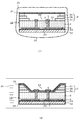
- top view and sectional drawing which show an example of the light-emitting device using the element substrate obtained by the manufacturing method of this invention. It is the top view and sectional drawing which show the 1st laminated body after (A) process in an example of embodiment of the manufacturing method of the element substrate of this invention, or (a) process. It is sectional drawing which shows typically the (B) process or the (b) process in the manufacturing method of the element substrate of this invention. It is the top view and sectional drawing which show the 1st laminated body after the (B) process in an example of embodiment of the manufacturing method of the element substrate of this invention, or the (b) process.
- FIG. 1A is a plan view showing an example of a light emitting device using an element substrate obtained by the manufacturing method of the present invention, and FIG.
- a plate-like ceramic base 2 (hereinafter simply referred to as a base) having a flat main surface and an upper main surface 21 of the base 2 are formed.
- a ceramic frame body 3 having a tapered inner wall surface 25 that expands substantially upward, and a part of the upper main surface of the base body 2 is a bottom surface 24, and the inner wall surface of the frame body Is applied to the manufacture of the element substrate 1 having the light emitting element mounting portion 22 on the bottom surface 24 of the cavity 4 formed as a side surface.
- a plate-like substrate having a flat main surface refers to a substrate having a flat surface with a level at which both the upper and lower main surfaces can be recognized as a flat plate shape at the visual level.
- substrate refers to a substrate whose upper and lower main surfaces are such flat surfaces.
- the upper main surface of the base body is simply referred to as a main surface
- the lower main surface is referred to as a back surface.
- the abbreviations indicate the levels that can be recognized at the visual level unless otherwise specified.
- the element connection terminals 5 that are electrically connected to the pair of electrodes of the light emitting element are provided on the bottom surface 24 of the cavity 4 constituted by a part of the main surface 21 of the base 2.
- a pair of substantially rectangular shapes are provided so as to face the outer periphery of the element mounting portion 22, specifically, both sides.
- a pair of external connection terminals 6 that are electrically connected to an external circuit are provided on the back surface 23 of the base 2, and the element connection terminals 5 and the external connection terminals 6 are electrically connected to the inside of the base 2.
- a pair of through conductors 7 is provided.
- the element connection terminal 5, the external connection terminal 6, and the through conductor 7 may be collectively referred to as a “wiring conductor”.
- the light emitting element 11 is mounted on the mounting portion 22 of the element substrate 1, and the electrode of the light emitting element 11 (not shown) is electrically connected to the element connection terminal 5 by the bonding wire 12.
- the light emitting device 10 is further configured by providing a sealing layer 13 so as to fill the cavity 4 while covering the light emitting element 11 and the bonding wire 12 arranged as described above on the bottom surface 24 of the cavity 4. ing.
- the element substrate 1 in the light emitting device 10 shown in FIG. 1 is taken as an example, with reference to FIGS. 2 to 7, the manufacturing method of the present invention having steps (A) to (F) and the following (a)
- the production method of the present invention having steps (e) to (e) will be described.
- the steps (A) and (a) are described as steps (A)
- the steps (B) and (b) are described as steps (B).
- the steps (E) and (d) will be described as step (E)
- the steps (F) and (e) will be described as step (F).
- description of (c) process description of (C) process and (D) process applies mutatis mutandis.
- Step (A) Using a ceramic composition containing ceramic powder and a binder resin, a plate-like green sheet for a substrate having a flat main surface, and a plurality of sheets each having an opening having a similar shape and a different area at the center.
- a plate-like green sheet for laminating a frame is manufactured, the plurality of green sheets for laminating the frame are formed on the upper main surface of the green sheet for the base, and the inner wall surface of the laminated part of the green sheets for laminating the frame is stepped
- a step of manufacturing a stacked body hereinafter referred to as a first stacked body in which the area of the opening is ascending from the lower side (hereinafter referred to as a first stacked step).
- Step (B) Process The process which rounds the step-like corner which the laminated part of the green sheet for frame lamination has on the inner wall surface by pressing the 1st laminated body obtained at the above-mentioned (A) process isotropically pressure (below) , Referred to as a first isotropic pressure applying step).
- Step (C) Using a ceramic composition containing ceramic powder and a binder resin, a green sheet for laminating a frame having a shape similar to the opening of the green sheet for laminating a frame at the center and having an area laminated at the lowermost part The process of producing the plate-shaped frame outermost layer green sheet which has an opening part smaller than the area of this opening part.
- Step (D) Step The green sheet for the outermost layer of the frame obtained in the step (C) is laminated at the uppermost portion of the first laminate after the step (B) with the center of the opening at the lowermost portion.
- a step of further laminating so as to substantially coincide with the center of the opening of the green sheet for laminating frames (hereinafter referred to as a second laminating step).
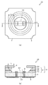
- 2 to 7 are a plan view and a cross-sectional view schematically showing an example of an embodiment of the element substrate manufacturing method of the present invention for each process.
- the members used for manufacturing are described with the same reference numerals as the members of the finished product.
- a ceramic base and a green sheet for a ceramic base are indicated by the same reference numeral 2
- an element connection terminal and an element connection terminal paste layer are indicated by the same reference numeral 5. is there.
- FIG. 2 is a top view (a) of 1 A of 1st laminated bodies obtained by the 1st lamination process (process of (A)) in an example of the manufacturing method of this invention. And an XX line sectional view (b) thereof.
- a step of producing a substantially flat green sheet 2 for a substrate using a ceramic composition containing a ceramic powder and a binder resin step (A-1)), and a shape similar to each other at the center A plurality of (three in FIG.
- step (A-2) plate-shaped frame stacking green sheets (3a, 3b, 3c) each having an opening having a different area (step (A-2)), The following description will be made in the order of the step of laminating the green sheets obtained in the steps (A-1) and (A-2) in a predetermined order (step (A-3)).
- Ceramic composition containing the ceramic powder and the binder resin used for the production of the green sheet 2 for the substrate include ceramic compositions usually used for the production of element substrates.
- a ceramic composition is mentioned.
- the binder resin and other optional components contained in the ceramic composition are as described later, and the same materials are used in the above ceramic compositions.
- the ceramic composition which comprises a green sheet is finally baked by the (F) process, and becomes a ceramic, since each said ceramic composition differs in a calcination temperature, it is demonstrated normally with the base
- the frame 3 is made of the same kind of ceramics including the outermost layer of the frame. As long as the ceramic composition that constitutes each green sheet is composed of the same kind of ceramics, the raw material composition can be changed for each green sheet as necessary, but there is usually no difference in the raw material composition between the green sheets. Is used.
- a glass ceramic composition for LTCC is used as the ceramic composition, it has ease of manufacturing and easy processability, so that the taper formed on the inner wall surface of the frame body in particular. The effects of angle accuracy and uniformity can be remarkably obtained for the inclination.
- the light can be produced without providing a reflective layer such as silver on the bottom and side surfaces of the cavity.
- An element substrate with high directivity and light extraction efficiency can be manufactured.
- a haze value measured by JIS K 7105 is used as an index for evaluating diffuse reflectance. The value is preferably 95% or more, and more preferably 98% or more.
- a glass ceramic composition for LTCC is selected as the ceramic composition, it can be fired at low temperature. Therefore, if necessary, an element substrate having a reflective layer such as silver on the bottom surface or side surface of the cavity may be provided once. Can be produced by firing.
- the raw material composition can be adjusted so that the bending strength is 250 MPa or more from the viewpoint of suppressing damage or the like when the light emitting element is mounted and thereafter used. preferable.
- the glass ceramic composition for LTCC contains glass powder, ceramic powder, and a binder resin, and is prepared by adding a plasticizer, a dispersant, a solvent, and the like as necessary.
- the glass transition point is preferably 550 ° C. or higher and 700 ° C. or lower.
- the glass transition point is less than 550 ° C., degreasing may be difficult, and when it exceeds 700 ° C., the shrinkage start temperature becomes high and the dimensional accuracy may be lowered.
- Tc which is the crystallization peak temperature measured by DTA (differential thermal analysis) is preferably 880 ° C. or less. When Tc exceeds 880 ° C., the dimensional accuracy may be reduced.
- SiO 2 is 57 mol% or more and 65 mol% or less
- B 2 O 3 is 13 mol% or more and 18 mol% or less
- CaO is 9 mol% in terms of the following oxide conversion mol%. above, 23 mol% or less, Al 2 O 3 of 3 mol% or more, 8 mol% or less, 0.5 mol% or more in total of at least one selected from K 2 O and Na 2 O, is preferably one containing less 6 mol%. Thereby, it becomes easy to improve the flatness of the surface of the obtained base or frame.
- SiO 2 becomes a glass network former.
- the content of SiO 2 is preferably 58 mol% or more, more preferably 59 mol% or more, and particularly preferably 60 mol% or more.
- the content of SiO 2 is preferably 64 mol% or less, more preferably 63 mol% or less.
- B 2 O 3 is a glass network former. If the content of B 2 O 3 is less than 13 mol%, there is a possibility that the glass melting point or the glass transition point becomes excessively high. On the other hand, when the content of B 2 O 3 exceeds 18 mol%, it is difficult to obtain a stable glass and the chemical durability may be lowered.
- the content of B 2 O 3 is preferably 14 mol% or more, more preferably 15 mol% or more. Further, the content of B 2 O 3 is preferably 17 mol% or less, more preferably 16 mol% or less.
- Al 2 O 3 is added to increase the stability, chemical durability, and strength of the glass.
- the content of Al 2 O 3 is less than 3 mol%, the glass may become unstable.
- the content of Al 2 O 3 exceeds 8 mol%, the glass melting temperature and the glass transition point may be excessively high.
- the content of Al 2 O 3 is preferably 4 mol% or more, more preferably 5 mol% or more.
- the content of Al 2 O 3 is preferably 7 mol% or less, more preferably 6 mol% or less.
- CaO is added to increase glass stability and crystal precipitation, and to lower the glass melting temperature and glass transition point.
- the content of CaO is less than 9 mol%, the glass melting temperature may be excessively high.
- the content of CaO exceeds 23 mol%, the glass may become unstable.
- the content of CaO is preferably 12 mol% or more, more preferably 13 mol% or more, and particularly preferably 14 mol% or more.
- the CaO content is preferably 22 mol% or less, more preferably 21 mol% or less, and particularly preferably 20 mol% or less.
- K 2 O and Na 2 O are added to lower the glass transition point.
- the glass melting temperature and the glass transition point may be excessively high.
- the total content of K 2 O and Na 2 O exceeds 6 mol%, chemical durability, particularly acid resistance may be lowered, and electrical insulation may be lowered.
- the total content of K 2 O and Na 2 O is preferably 0.8 mol% or more and 5 mol% or less.
- glass powder is not necessarily limited to what consists only of the said component, Other components can be contained in the range with which various characteristics, such as a glass transition point, are satisfy
- the glass powder is obtained by melting a glass raw material prepared so as to have a glass composition as described above to produce glass, and pulverizing the obtained glass by a dry pulverization method or a wet pulverization method.
- a dry pulverization method or a wet pulverization method.
- water is preferable as the solvent.
- the pulverization is performed using a pulverizer such as a roll mill, a ball mill, or a jet mill.
- the 50% particle size (D 50 ) of the glass powder is preferably 0.5 ⁇ m or more and 2 ⁇ m or less.
- the 50% particle size of the glass powder is less than 0.5 ⁇ m, the glass powder is likely to aggregate, making it difficult to handle and uniformly dispersing.
- the 50% particle size of the glass powder exceeds 2 ⁇ m, the glass softening temperature may increase or the sintering may be insufficient.
- the particle size is adjusted by, for example, classification as necessary after pulverization.
- a particle size means the value obtained with the particle diameter measuring apparatus by a laser diffraction scattering method.
- the ceramic powder those conventionally used for the production of LTCC substrates can be used without particular limitation.
- alumina powder, zirconia powder, or a mixture of alumina powder and zirconia powder can be suitably used.
- the mixture of an alumina powder and a zirconia powder is used preferably as said ceramic powder.
- the mixture of alumina powder and zirconia powder is preferably a mixture in which the mixing ratio of (alumina powder: zirconia powder) is 90:10 to 60:40 in terms of mass ratio.
- the 50% particle size (D 50 ) of the ceramic powder is preferably 0.5 ⁇ m or more and 4 ⁇ m or less, for example, in any of the above cases.
- a glass ceramic mixture is prepared by blending and mixing such glass powder and ceramic powder such that the glass powder is 30% by mass or more and 50% by mass or less, and the ceramic powder is 50% by mass or more and 70% by mass or less. Get.
- a slurry-like glass ceramic composition is obtained by adding a binder resin and, if necessary, a plasticizer, a dispersant, a solvent and the like to the glass ceramic mixture and mixing them sufficiently.
- a binder resin for example, polyvinyl butyral, acrylic resin or the like is preferably used.
- the blending amount of the binder resin in the glass ceramic composition is preferably 5 to 15 parts by mass with respect to 100 parts by mass of the glass ceramic mixture.
- the plasticizer for example, dibutyl phthalate, dioctyl phthalate, butyl benzyl phthalate and the like are used.
- organic solvents such as toluene, xylene, 2-propanol, 2-butanol and the like are preferably used.
- the glass ceramic mixture is used instead of the glass ceramic composition for LTCC.
- Each ceramic composition in the form of a slurry is prepared using a conventionally known ceramic powder mainly composed of aluminum oxide powder or aluminum nitride, with the other components being the same as described above.
- the slurry-like glass ceramic composition obtained above is formed into a sheet having a predetermined shape and thickness so that the shape and thickness after firing are within a desired range by a doctor blade method or the like, and dried. Thereby, the green sheet 2 for base
- each green sheet is formed so as to have an excess portion around the area to be the element substrate. Then, by using this surplus portion and fixing to a support or the like prepared for each process, it is possible to prevent printing misalignment such as laminating misalignment and the following wiring conductor paste.
- the excess part of the green sheet is separated from the region to be the element substrate by dividing grooves or the like, and is separated from the element substrate after firing.
- a multi-element, multiple-element substrate unit which is usually used when manufacturing a wiring substrate such as an element substrate, is connected.
- a method of producing individual element substrates by producing a substrate (hereinafter referred to as a connecting substrate) and obtaining a step of dividing the substrate is employed.
- the green sheet is preferably formed so as to further have the above-described surplus portion so as to have a size in which regions serving as a plurality of element substrates are arranged. This surplus portion is applied not only to the base green sheet but also to a frame stacking green sheet and a frame outermost layer green sheet which will be described later.
- the following description will be made in units of one element substrate. However, even when the above-mentioned surplus portion is provided or when a connection substrate is manufactured, formation of wiring conductor layers and formation of through conductors performed on the element substrate The processing itself is not particularly changed.
- the timing of separation and division may be before firing the light-emitting element on the element substrate as long as it is fired, or may be before soldering and mounting on the printed wiring board or the like after mounting the light-emitting element.
- the green sheet 2 for the substrate includes a paste layer for wiring conductors (including a paste layer 5 for element connection terminals, a paste layer 6 for external connection terminals, and a paste layer 7 for through conductors, These wiring conductor paste layers are usually formed on the base green sheet 2 at a stage prior to the lamination of the frame laminating green sheets. .
- a through hole is formed, and a through conductor paste layer 7 is formed so as to fill the through hole.
- the element connection terminal paste layer 5 is formed in a substantially rectangular shape so as to cover the through conductor paste layer 7 on the main surface 21, and the external connection terminal is electrically connected to the through conductor paste layer 7 on the back surface 23.
- a paste layer 6 is formed.
- a conductor paste used for forming a wiring conductor paste layer for example, a metal powder mainly composed of copper, silver, gold, etc., added with a vehicle such as ethyl cellulose, and a solvent, etc., if necessary, is made into a paste.
- a metal powder composed of silver, a metal powder composed of silver and platinum, or a metal powder composed of silver and palladium is preferably used.
- the wiring conductor paste layer As the metal powder of the conductor paste used for the formation, a metal powder mainly composed of a high melting point metal such as tungsten or molybdenum may be used instead of the metal powder mainly composed of copper, silver, gold or the like.
- Examples of a method for forming the element connection terminal paste layer 5, the external connection terminal paste layer 6, and the through conductor paste layer 7 include a method of applying or filling the conductor paste by a screen printing method.
- the film thickness of the element connection terminal paste layer 5 and the external connection terminal paste layer 6 to be formed is preferably such that the film thickness of the element connection terminal and external connection terminal finally obtained is a predetermined film thickness. It is adjusted to 5 to 15 ⁇ m.
- a reflective layer may be provided on a portion of the base 2 other than the light emitting element mounting portion 22 and the element connection terminal 5 forming portion in the region to be the cavity bottom surface 24.
- a thermal via is embedded in the base 2 in a direction perpendicular to the main surface 21 of the base 2 or a heat dissipation layer is provided in a direction parallel to the main surface 21,
- a metal paste layer for forming these at a desired position of the base green sheet 2 is formed in the same manner as forming the wiring conductor paste layer.
- a metal paste the same thing as the said conductor paste can be used according to the kind of ceramic composition.
- the base green sheet 2 has been described above, but the base green sheet 2 does not necessarily have to be a single green sheet, and may be a laminate of a plurality of green sheets.
- the method for forming each part can be changed as appropriate as long as the element substrate can be manufactured.
- A-2) Production of Green Sheets (3a, 3b, 3c) for Laminating Frames The three green sheets (3a, 3b, 3c) for laminating frames shown in FIG.
- a ceramic composition is used to form a sheet having a thickness described below, in the same manner as the green sheet 2 for a substrate, usually using a ceramic composition having the same raw material composition.
- the thickness of the frame stacking green sheet used in the manufacturing method of the present invention is determined by the number of frame stacking green sheets used.
- the number of the green sheets for laminating the frame it is essential to use a plurality of sheets in order to taper the inner wall surface of the obtained frame 3, but the number is not particularly limited as long as the number is two or more.
- the number and thickness of the frame stacking green sheets to be used are appropriately adjusted depending on the height of the frame 3 of the element substrate 1 finally obtained, the taper angle of the inner wall surface 25, and the like.
- the number of green sheets for laminating frames used is preferably 2 to 6.
- the height of the frame 3 that is, the distance from the bottom surface 24 of the cavity 4 to the highest position of the frame 3 and the taper angle of the inner wall surface 25 of the frame 3 are mounted. It is designed so that light from the light emitting element can be sufficiently reflected in the light extraction direction.
- the light emitting element is mounted from the viewpoint of efficiently filling the shape of the product on which the light emitting device is mounted and the sealing material containing the phosphor for wavelength conversion. It is preferable that the height of the light emitting element is 100 to 500 ⁇ m higher than the height of the light emitting element.
- the height of the frame 3 is more preferably equal to or less than the height of 450 ⁇ m added to the height of the highest part of the light emitting element, and more preferably equal to or less than the height of 400 ⁇ m.
- the taper angle of the inner wall surface 25 of the frame 3 is 20 to 80 °, which is the angle (indicated by ⁇ in FIG.
- the height of the frame 3 is the total thickness of a laminate obtained by laminating and baking a frame laminate green sheet and a frame outermost layer green sheet described below.
- the thickness of the frame laminate green sheet and the frame outermost layer green sheet is preferably 50 to 200 ⁇ m, more preferably 50 to 100 ⁇ m, as the thickness after firing. . If this thickness is less than 50 ⁇ m, laminating misalignment or the like is likely to occur, and if it exceeds 200 ⁇ m, a gap is generated between the frame and the green sheet for laminating the frame when covered with the outermost layer green sheet in step (E). There is a fear.
- the thickness after firing is preferably smaller than the height of the light emitting element to be mounted.
- the thickness of these green sheets for forming the frame 3 may differ between each green sheet, and may be the same thickness.
- an opening having a shape similar to the shape of the bottom surface 24 of the cavity 4 is then formed in the center by a normal method.
- the shape of the bottom surface 24 is circular.
- the size of the opening is the same size as the bottom surface 24 of the cavity 4 for the frame laminating green sheet 3a constituting the lowermost layer, and the frame laminating green sheet 3b laminated thereon,
- the frame stacking green sheet 3c stacked on the top and the opening are sequentially formed so as to have a large area.
- the frame stacking green sheets 3a, 3b, and 3c are configured as described above, when the frame stacking green sheets 3a, 3b, and 3c are stacked in that order, the stacked portion of the frame having a stepped inner wall surface is provided. can get.
- the taper angle of the inner wall surface 25 of the frame 3 finally obtained is the thickness of the green sheets 3a, 3b, and 3c for laminating the frames (indicated by t1, t2, and t3, respectively in FIG. 2). The adjustment is made according to the difference in size of these openings.
- the radii of the openings of the frame stacking green sheets 3a, 3b, and 3c are r1, r2, and r3, respectively, the relationship r1 ⁇ r2 ⁇ r3 holds, and the frame stacking green
- the width of the portion of the upper surface of the sheet 3a where the frame laminate green sheet 3b is not laminated is r2-r1 (indicated by x1 in FIG. 2), and the frame laminate green on the upper surface of the frame laminate green sheet 3b.
- the width of the portion where the sheet 3c is not laminated is r3-r2 (indicated by x2 in FIG. 2).
- the taper angle of the inner wall surface 25 of the frame 3 is 45 ° as the value of ⁇
- the size of the opening is set so that x1 / t1 and x2 / t2 are 1. adjust.
- the step-like inner wall surface of the laminated portion of the frame obtained by laminating the green sheets for laminating the frame is provided for each step of these steps.
- the inner wall surface of the frame 3 finally obtained when the width (corresponding to x1 and x2 above) of the surface parallel to the principal surface of the frame is equal to the height of the step (corresponding to t1 and t2 above)
- the taper angle of 25 can be 45 ° as the value of ⁇ .
- the size of the opening is adjusted so that the width of each step of the staircase is 0.6 to 1.4 times the height of the step. .
- the relationship between the width and height of each step of the stairs is preferably 0.8 to 1.2 times, and in this case, the obtained value of the angle ⁇ is 60 to 40 °.
- the taper of the inner wall surface 25 of the frame 3 is adjusted by adjusting the thickness of the green sheet for frame lamination and the size of the opening so that the relationship between the width and height is different in each step of the stairs. It is also possible to adopt a configuration in which the angles are partially different.
- A-3) Lamination of each green sheet 3 produced in the step (A-2) on the main surface 21 of the substrate green sheet 2 having the wiring conductor paste layer produced in the step (A-1).
- a plurality of frame stacking green sheets 3a, 3b, and 3c are stacked in that order from the main surface side of the base green sheet 2 to obtain a first stacked body 1A.
- the green sheet is used as a laminating method.
- a method in which a laminate is formed by pressure bonding with each other by uniaxial pressing or the like is preferable.
- the green sheets are laminated by uniaxial pressing to obtain the first laminated body 1A
- the green sheets stacked in the order described above are sandwiched between spacers such as a PET film, preferably an excess part of the green sheets
- spacers such as a PET film
- the entire region including the spacers is fixed in a region such as, and this is pressure-bonded by a uniaxial press machine and laminated.
- the conditions at the time of lamination depend on the number of green sheets to be laminated, the thickness, the type of ceramic composition, the raw material composition, and the like, but conditions of 60 to 80 ° C. and 1 to 4 MPa for about 1 to 3 minutes are preferable.
- the spacer is removed and the first laminated body 1A is subjected to the next step (B). If necessary, the first laminated body 1A is sandwiched between the spacers (B) ) You may use for a process.
- isotropic pressure pressurization using a 1st resin film at the (B) process when performing the said uniaxial pressurization, it is the 1st resin film on what overlapped each green sheet. May be provided and used for the next step (B) together with the first laminate 1A without removing it after uniaxial pressing.
- the first resin film functions sufficiently as the spacer, it is not necessary to use a separate spacer.
- a spacer is further provided thereon. Disposed and uniaxially pressurized.
- FIG. 3 is a cross-sectional view schematically showing the step (B) in the element substrate manufacturing method of the present invention.
- FIG. 4 is a plan view (a) showing the first laminate 1B after the step (B) is completed by an example of the manufacturing method of the present invention, and a sectional view (b) taken along the line XX.
- isotropic pressure is a generally used method for laminating and integrating ceramic green sheets.
- isotropic pressure is used to pressurize the object to be pressed with a uniform pressure (isotropic pressure) from all directions so that the green sheets are firmly joined to each other.
- a warm isostatic press (WIP) system is preferably used.
- the warm isostatic pressurization method (hereinafter also referred to as the WIP method) uses a heated fluid or liquid such as warm water as a pressure medium, and the green sheet laminate is pressurized via this pressure medium. By applying an isotropic pressure, the stacked green sheets are pressure-bonded with equal pressure from all directions.
- the first isotropic pressure pressurizing step is performed by using the first laminated body 1A obtained in the step (A) in the frame laminating green sheets 3a, 3b, 3c. This is performed for the purpose of rounding the stepped corners of the laminated portion 3 ′ on the inner wall surface. Therefore, the first isotropic pressure is selected by selecting conditions that can achieve this purpose.
- the radius of curvature R of the rounded step-like corner is 0 for the thickness of the green sheet for each of the green sheets for laminating a frame having the rounded corner. It is preferable to apply isotropic pressure so that a value obtained by multiplying by .7 to 1.5 is obtained.
- the radius of curvature R of the stepped corners rounded by the step (B) is 0.85 to the thickness of the green sheet for each green sheet for laminating frames having the rounded corners. It is a value multiplied by 1.2.
- the unit of thickness is mm.
- stacking is rounded
- the curvature radii are R1, R2, and R3. From the relationship between the thickness of the green sheet and the radius of curvature, R1 is preferably t1 ⁇ 0.7 to t1 ⁇ 1.5 (mm), and t1 ⁇ 0.85 to t1 ⁇ 1.2 (mm). More preferred.
- R2 is t2 ⁇ 0.7 to t2 ⁇ 1.5 (mm)
- R2 is preferably t3 ⁇ 0.7 to t3 ⁇ 1.5 (mm)
- R2 is t2 ⁇ 0.85 to t2 ⁇ 1.2 (mm)
- R3 is more preferably t3 ⁇ 0.85 to t3 ⁇ 1.2 (mm)
- the first isotropic pressure pressurization in the production method of the present invention uses, for example, an isotropic pressure pressurization apparatus conventionally used to integrate the ceramic green sheet laminate described above without any particular limitation. Can do. And, the condition of the isotropic pressure is preferably set such that the laminated corner 3 ′ of the green sheets 3a, 3b, 3c for frame lamination has rounded stepped corners on the inner wall surface, and the curvature radius R1, The process is executed by setting R2 and R3 to such a preferable range as described above.
- an apparatus corresponding to the WIP method is preferably used as the isotropic pressure pressurization apparatus.
- FIG. 3 is a diagram schematically showing a first isotropic pressure pressing step in the manufacturing method of the present invention, taking as an example a case where a WIP hydraulic press is used as the isotropic pressure pressing device.
- FIG. 3 (1) is a diagram showing a preparation for performing the first laminate 1A for use in a hydraulic press.
- FIG. 3 (2) is a diagram showing a state where the first laminated body 1A prepared as shown in FIG. 3 (1) is pressurized with an isotropic pressure.
- the first laminated body 1A is usually placed on a support plate 32 (for example, a metal support plate such as stainless steel). Is done.
- a spacer 33 such as a PET film is sandwiched between the first laminated body 1A and the support plate 32 so that they are not in direct contact with each other. By sandwiching this spacer, it is possible to prevent the external connection terminal paste layer 6 from adhering to the support plate 32.
- the spacer 33 the spacer used in the pressure bonding by the uniaxial press machine may be used as it is.
- the upper side of the first laminated body 1A is added.
- a first resin film 31 is disposed on the pressure surface.
- the various laminated members on the top and bottom of the first laminated body 1A are put in a resin bag 34 for vacuum packaging.
- a resin bag 34 for vacuum packaging.
- the air 35 is removed from the resin bag 34, vacuum packaging is performed, the whole resin bag is placed in a pressure vessel (not shown), and the pressure vessel is sealed to complete the preparation.
- Isotropic pressure is applied to the first laminated body 1A by hydraulically pressing the sealed pressure vessel.
- the pressure vessel is immersed in a hot water tank filled with water heated to the following preferable temperature conditions.
- the internal pressure of the pressure vessel is increased and maintained for several minutes to several tens of minutes under the following preferable pressure conditions, and then the internal pressure of the pressure vessel is released.
- FIG. 3B shows a state of the first laminate 1A during isotropic pressure pressurization by the pressure of water 36 (warm water).
- the pressure vessel is recovered from the hot water tank, the resin bag 34 is taken out from the pressure vessel, and the first laminated body 1B after the isotropic pressure application in which various members are laminated vertically is taken out from the resin bag 34. Furthermore, by removing the support plate 32, the spacer 33, and the first resin film 31, the first isotropic pressure is finished.
- the temperature condition is that of the binder resin contained in the green sheet for frame lamination.
- a temperature range that exceeds the glass transition point and is 20 ° C. or higher than the glass transition point is preferred.
- the preferable temperature range is approximately 60 to 80 ° C.
- the pressure condition for the first isotropic pressurization is preferably a pressure range of 5 to 30 MPa, and more preferably 10 to 20 MPa.
- the isotropic pressure is preferably about 3 to 20 minutes.
- the first resin film 31 disposed on the upper pressure surface of the first laminated body 1A has a frame body when the first isotropic pressure is applied. Stepped corners are formed by the close contact between the stepped inner wall surface of the laminated portion 3 'of the green sheets 3a, 3b, 3c for lamination and the bottom surface of the cavity, and isotropic pressure pressing under the above temperature and pressure conditions. Therefore, it is required to have such a property that pressure acts so as to be appropriately crushed.
- the first resin film 31 is preferably a resin film having a thickness of 50 to 80 ⁇ m and a breaking strength measured by JIS C 2318 of 150 to 210 MPa.
- the breaking strength refers to the breaking strength measured according to JIS C 2318.
- the film thickness of the resin film is more preferably 65 to 75 ⁇ m. If the film thickness of the resin film is less than 50 ⁇ m, the corners of the steps may not be sufficiently rounded. If it exceeds 80 ⁇ m, the green sheets 3 a, 3 b, 3 c for laminating frames as shown in FIG. The adhesion of the first resin film 31 to the lower wall portion of the laminated portion 3 ′, that is, the inner wall portion formed by the frame laminating green sheet 3a may not be sufficient.
- the breaking strength of the first resin film 31 is more preferably 160 to 190 MPa. If the breaking strength of the first resin film 31 is less than 150 MPa, the corners of the steps may not be sufficiently rounded, and if it exceeds 210 MPa, the corners of the steps are crushed more than necessary, and a desired taper angle is obtained. It may not be obtained.
- the material of the first resin film used in the present invention is not particularly limited as long as it is a resin film having a relationship between the preferable film thickness and the breaking strength, and a specific material is PET.
- the frame outermost layer green sheet 3d is the same as each green sheet described in steps (A-1) and (A-2).
- the ceramic composition containing ceramic powder and binder resin is used.
- the ceramic composition to be used is the same ceramic composition as the green sheet 2 for substrates and the green sheets 3a, 3b, 3c for laminating frames as described in the step (A-1).
- the raw material composition can be adjusted as appropriate. Usually, the same ceramic composition as that of the green sheet 2 for a substrate and the green sheets 3a, 3b, and 3c for laminating a frame is used as the raw material composition.
- the frame outermost layer green sheet 3d is formed into a sheet-like molded article having the predetermined thickness described in the step (A-2) by the same method as the base green sheet 2 described above. After molding, it is produced by forming a through-hole having an opening with the following shape and size in the central portion by a normal method.
- the opening of the frame outermost layer green sheet 3d has a shape similar to the opening of the frame stacking green sheets 3a, 3b, and 3c, that is, in this example, is circular, and the area is stacked at the lowermost portion. It is formed so as to be smaller than the area of the opening of the laminated green sheet 3a.
- the size of the opening of the frame outermost layer green sheet 3d is such that, after lamination, the frame outermost layer green sheet 3d is subjected to second isotropic pressure pressurization in step (E) described later. Is large enough to cover the inner wall surface from the uppermost surface of the frame stacking green sheet stacking portion 3 ′ and not to reach the element connection terminal paste layer 5 on the main surface of the base green sheet 2. If it is, it will not be restrict
- the size of the opening of the frame outermost layer green sheet 3d is preferably such that, as shown in this example, the end surface 8 constituting the opening when stacked is the above-described frame stacking green sheet stacking portion 3. From the position at the top of the inner wall of ', that is, the position indicated by E in FIG. 5 (b), the length covering the inner wall surface of the laminated portion 3', that is, the inner position as indicated by L in FIG. That's it.
- the length L of the frame outermost layer green sheet 3d is longer than the length covering the inner wall surface of the frame stacking green sheet laminate 3 ', a part of the frame outermost layer green sheet 3d is formed. Covers the bottom surface 24 of the cavity 4.
- the frame outermost layer green sheet 3d having such a configuration may be used as necessary.
- the length L covers the inner wall surface of the frame stacking green sheet stacking portion 3 ′.
- the length is equal to the length.
- the frame outermost layer green sheet 3d is bent at the portion covering the inner wall surface of the frame stacking green sheet stacking portion 3 ′ when being bent by the second isostatic pressing in the step (E). Since the film is stretched in the circumferential direction, a change in the length direction may occur.
- the frame outermost layer green sheet 3d is bent by the second isotropic pressure in step (E). At this time, the inner wall surface is covered from the uppermost surface of the frame stacking green sheet stacking portion 3 ′, and the length is adjusted so that the end surface 8 of the opening reaches the main surface 21 of the base green sheet 2.
- the frame outermost layer green sheet 3d may be prepared in advance when, for example, another green sheet is prepared in the step (A), or after the step (B), the second lamination step. You may do it alone before.
- the frame outermost layer green sheet 3d may have a metal paste layer for the reflective layer on the upper surface when laminated.
- the metal paste layer can be formed by the same method as that for forming the metal paste layer for the reflective layer on the green sheet 2 for the substrate.
- the same paste as the conductor paste described in the preparation of the green sheet 2 for the substrate in the step (A-1) can be used depending on the type of the ceramic composition.
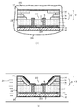
- FIG. 5 is a plan view (a) of the second laminated body 1C obtained by the second laminating process (D) in the example of the manufacturing method of the present invention and its X. It is a figure which shows -X-ray sectional drawing (b).
- step (D) a plate-shaped frame outermost layer constituting the outermost layer of the frame 3 produced in the step (C) on the first laminate 1B obtained in the step (B).
- the green sheet 3d for use is laminated.
- the frame outermost layer green sheet 3d produced in the step (C) is laminated on the top of the first laminate 1B obtained in the step (B) and the opening is laminated on the bottom.
- the second laminated body 1 ⁇ / b> C is obtained by laminating so as to be located inside the opening of the frame laminated green sheet 3 a.
- a method is preferable in which the frame outermost layer green sheet 3d is pressure-bonded to the first laminate 1B by uniaxial pressing or the like to obtain a laminate.
- the frame outermost layer green sheet 3d on the first laminate 1B are stacked in a spacer such as a PET film, and preferably, the entire region including the spacer is fixed in a region such as a surplus portion of the green sheet, and this is pressure-bonded and laminated by a uniaxial press.
- the conditions at the time of lamination depend on the thickness of the green sheet to be laminated, the kind of ceramic composition, the raw material composition, etc., but conditions of 60 to 80 ° C. and 1 to 4 MPa for about 1 to 3 minutes are preferable.
- the spacer is removed and the second laminated body 1C is subjected to the next step (E). If necessary, the second laminated body 1C is sandwiched between the spacers and the next (E ) You may use for a process.
- the green sheet 3d for frame outermost layers is added to the 1st laminated body 1B.
- the second resin film may be disposed on the superposed layer, and after uniaxial pressing, the second resin film may be used for the next step (E) together with the second laminated body 1C without being removed.
- the second resin film functions sufficiently as the spacer, it is not necessary to use a separate spacer.
- a spacer is further provided thereon. Disposed and uniaxially pressurized.
- FIG. 6 is a cross-sectional view schematically showing step (E) in the element substrate manufacturing method of the present invention.
- FIG. 7: is a top view (a) which shows the 2nd laminated body 1C after the (E) process by an example of the manufacturing method of this invention, ie, the unsintered element board
- the second isotropic pressure is applied to the second laminated body 1C obtained in the step (D) as shown in the sectional view (b) of FIG. This is performed for the purpose of processing the outermost layer green sheet 3d so as to cover the inner wall surface from the uppermost surface of the frame stacking green sheet laminate portion 3 '. Therefore, the second isotropic pressure is selected by selecting conditions that can achieve this purpose.
- the frame outermost layer green sheet 3d is positioned at the uppermost position of the inner wall of the frame stacking green sheet stacking portion 3 ′, that is, the position indicated by E in FIG.
- the portion of the length L from the position E to the end face 8 constituting the opening is processed so as to cover the entire inner wall surface of the green sheet laminate portion 3 ′ for frame lamination, and the unsintered element substrate 1.
- the end surface 8 of the processed frame outermost layer green sheet 3d is formed on the bottom surface 24 of the cavity 4 which is partially formed by the main surface 21 of the base green sheet 2. Has reached.
- the length L of the frame outermost layer green sheet 3d is equal to the length covering the inner wall surface of the frame stacking green sheet stacking portion 3 '. Further, the end face 8 of the frame outermost layer green sheet 3d normally maintains the shape as it is even after the second isotropic pressure is applied. Therefore, as shown in FIG. 7 (b), the inner wall surface of the frame body in the green element substrate 1 to be obtained is located upward from the joint point between the frame outermost layer green sheet 3d and the base body green sheet 2. First, the lowermost portion constituted by the end surface 8 of the frame outermost layer green sheet 3d is positioned, and the frame inner wall surface constituted by the upper main surface of the frame outermost layer green sheet is substantially formed thereon. It becomes the structure in which a part is located.
- the inner wall surface of the frame body is at a lower position from the boundary portion with the base body to a position that is substantially the same height as the thickness of the frame outermost layer green sheet after firing.
- the structure of the element substrate of the present invention is formed such that it has a taper shape that expands toward the top, and the taper shape that expands toward the upper portion from the position above. Further, the shape of the end surface 8 of the frame outermost layer green sheet 3d is maintained substantially as it is after the firing step of the next step (F).
- the preferable taper angle of the portion having a taper shape that expands toward the upper part that substantially constitutes the inner wall surface of the frame is as described above.
- the finally obtained sintered element substrate has a tapered shape that expands toward the lower part.
- the taper angle (indicated by ⁇ in FIG. 1) is preferably approximately 60 ° or more and less than 90 °, and more preferably 70 or more and within 80 °.
- the sealant can be filled without any gaps.
- This angle can be adjusted by the length L from the uppermost position E of the inner wall of the frame laminated green sheet laminated portion 3 ′ to the end face 8 constituting the opening in the frame outermost layer green sheet 3 d. is there. Since the lowermost part of the wall surface in the frame has such a shape, the element substrate of the sealing layer 13 made of a filler such as a silicone resin or an epoxy resin that fills the cavity 4 when using this as a light emitting device. The peel strength can be increased.
- the second isotropic pressure pressurization for obtaining the unsintered element substrate 1 having the above-described configuration is the first isostatic pressure pressurization which is arranged on the upper pressurization surface of the laminate to be pressed in the first isostatic pressurization.
- the same operation can be performed except that the resin film is replaced with the second resin film. Therefore, as the isotropic pressure pressurizing device, a device corresponding to the WIP method is preferably used.
- a WIP hydraulic press since it is necessary to press at a temperature higher than the softening point of the binder resin contained in the green sheet for the purpose of bonding the layers, it is preferable to use a WIP hydraulic press.
- FIG. 6 is a diagram schematically showing a second isotropic pressure pressing step in the manufacturing method of the present invention, taking as an example the case where a WIP hydraulic press is used as the isotropic pressure pressing apparatus.
- a WIP hydraulic press is used as the isotropic pressure pressing apparatus.
- FIG. 6 (1) is a diagram showing preparations for performing the second laminated body 1C for use in a hydraulic press.
- FIG. 6B is a diagram showing a state where the second laminated body 1C prepared as shown in FIG. 6A is isotropically pressurized.
- the second laminated body 1C is usually placed on a support plate 32, for example, a metal support plate such as stainless steel.
- a spacer 33 such as a PET film is sandwiched between the second laminated body 1 ⁇ / b> C and the support plate 32 so that they are not in direct contact with each other.
- the spacer 33 the spacer used in the pressure bonding by the uniaxial press machine may be used as it is.
- the frame outermost layer green sheet 3d is bent from the uppermost position of the inner wall of the frame stacking green sheet stacking portion 3 ', and the length L portion covers the inner wall surface of the stacking portion 3'.
- a second resin film 37 is disposed on the upper pressure surface of the second laminated body 1C so as to be processed into a covering shape.
- the various laminated members on the upper and lower sides of the second laminated body 1C are put in a resin bag 34 for vacuum packaging.
- a resin bag 34 for vacuum packaging.
- an excess portion of the green sheet is used so that the second laminated body 1C and the various members do not move freely.
- the air 35 is removed from the resin bag 34 and vacuum-packed, and the whole resin bag is put into a pressure vessel (not shown) and the pressure vessel is sealed to complete the preparation.
- the second laminated body 1C is pressurized isotropically by hydraulically pressing the sealed pressure vessel. Specifically, the pressure vessel is immersed in a hot water tank filled with water heated to the following preferable temperature conditions. In this state, the internal pressure of the pressure vessel is increased and maintained for several minutes to several tens of minutes under the following preferable pressure conditions, and then the internal pressure of the pressure vessel is released.
- FIG. 6 (2) shows a state of the second laminated body 1C during isotropic pressure pressurization by the pressure of the water 36 which is hot water.
- the pressure vessel is recovered from the hot water tank, the resin bag 34 is taken out of the pressure vessel, and the second laminated body 1C after the isotropic pressure is applied, in which various members are laminated vertically from the resin bag 34, that is, the light emitting element substrate. Unsintered element substrate 1 is taken out. Furthermore, by removing the support plate 32, the spacer 33, and the second resin film 37, the second isotropic pressure is finished.
- the temperature condition is a temperature not higher than the glass transition point of the binder resin contained in the outermost layer green sheet of the frame and higher by 20 ° C. than the glass transition point.
- a range is preferred.
- the preferable temperature range is approximately 60 to 80 ° C.
- the temperature condition can be the same as the first isotropic pressure pressing condition.
- the pressure condition for the second isotropic pressurization is preferably a pressure range of 5 to 30 MPa, more preferably 10 to 20 MPa.
- the isotropic pressure pressurization time is preferably about 3 to 20 minutes, and both the pressure condition and pressurization time are the same as the first isotropic pressure pressurization condition.
- the second resin film 37 disposed on the upper pressure surface of the second laminate 1C is subjected to the above temperature and pressure during the second isotropic pressure.
- the frame outermost layer green sheet 3d is bent from the uppermost position of the inner wall of the frame stacking green sheet stacking portion 3 ′, and the length L portion covers the inner wall surface of the stacking portion 3 ′. It is required to have such a property that pressure acts so as to be sufficiently adhered to the covering shape.
- the second resin film 37 is preferably a resin film having properties of a film thickness of 30 to 50 ⁇ m and a breaking strength of 230 to 300 MPa.
- the film thickness of the resin film is more preferably 35 to 40 ⁇ m. If the film thickness of the resin film is less than 30 ⁇ m, the stepped shape of the inner wall surface of the green sheet laminate portion 3 ′ for laminating the frame body may appear on the surface of the green sheet 3 d for the outermost layer of the frame body, and exceeds 50 ⁇ m. And the corner
- the breaking strength of the second resin film 37 is more preferably 250 to 280 MPa. If the breaking strength of the second resin film 37 is less than 230 MPa, the adhesion of the outermost layer green sheet 3d to the frame lamination green sheet laminate portion 3 ′ may not be sufficiently obtained. If it exceeds, corners at the portion where the frame outermost layer green sheet 3d is bent are easily crushed.
- the material of the second resin film used in the present invention is not particularly limited as long as it is a resin film having a relationship between the preferable film thickness and breaking strength, and a specific material is PET.
- the firing temperature is preferably 800 ° C. to 930 ° C.
- the unsintered element substrate 1 can be held at a temperature of 500 ° C. or more and 600 ° C. or less for 1 hour or more and 10 hours or less.
- the degreasing temperature is less than 500 ° C. or the degreasing time is less than 1 hour, the binder or the like may not be sufficiently removed.
- the degreasing temperature is about 600 ° C. and the degreasing time is about 10 hours, the binder and the like can be sufficiently removed, and if it exceeds this, productivity and the like may be lowered.
- Calcination can be performed by appropriately adjusting the time within a temperature range of 800 ° C. to 930 ° C. in consideration of obtaining a dense structure of the base 2 and the frame 3 and productivity. Specifically, it is preferable to hold at a temperature of 850 ° C. or higher and 900 ° C. or lower for 20 minutes or longer and 60 minutes or shorter, particularly preferably at a temperature of 860 ° C. or higher and 880 ° C. or lower. If the firing temperature is less than 800 ° C., the sintering is insufficient and the base 2 and the frame 3 may not have a dense structure. On the other hand, if the firing temperature exceeds 930 ° C., the substrate may be deformed and the productivity may decrease.
- the firing temperature is 880 ° C.
- the firing temperature is 880 ° C.
- the firing temperature for sintering the unsintered element substrate 1 is preferably 1400 to 1700 ° C.
- the firing is preferably performed under a condition of holding at a temperature of 1400 ° C. or higher and 1700 ° C. or lower for several hours.
- a non-oxidizing atmosphere such as a reducing atmosphere (for example, a hydrogen atmosphere), an inert gas atmosphere, or a vacuum. Have to do.
- the firing conditions have been described above by taking the LTCC substrate and the alumina substrate as examples. However, the firing conditions are conventionally known conditions in the production of these ceramic substrates, and even when other ceramic materials are used, Firing may be performed according to firing conditions that are normally applied to the material.
- the unsintered element substrate 1 is fired to obtain the light emitting element substrate 1.
- the nickel connection is made so that the element connection terminals 5 and the external connection terminals 6 are entirely covered as necessary.
- a conductive protective layer usually used for protecting a conductor in an element substrate such as plating, chrome plating, silver plating, nickel / silver plating, gold plating, nickel / gold plating, etc., may be applied.
- nickel / gold plating in which gold plating is performed on nickel plating, is preferably used.
- the nickel plating layer uses a nickel sulfamate bath and the gold plating layer uses a potassium gold cyanide bath. Each can be formed by electrolytic plating.
- a metal paste layer mainly composed of highly reflective silver or the like cannot be formed as a reflective layer formed as necessary in the unsintered element substrate 1.
- a silver reflective layer or the like may be formed by combining a screen printing method, a sputter deposition method, an ink jet coating method, or the like after the firing step (F). .
- the manufacturing method of the element substrate of the present invention has been described by way of example, the manufacturing method of the present invention is not limited thereto. As long as it does not contradict the spirit of the present invention, the configuration can be changed as necessary.
- the taper slope is substantially uniform, and when the light emitting device is obtained, the light extraction efficiency and the light directivity are good. It will be a thing. Furthermore, according to the manufacturing method of the present invention, since the inclination angle of the taper on the side surface of the cavity can be controlled with high accuracy, an effect of increasing the degree of freedom in designing the optical device can be obtained. Further, it is economically advantageous because expensive equipment such as a mold for manufacturing is not required. Moreover, productivity is good compared with the method by a grinder etc.
- the cavity has a tapered shape in which the tapered side surface of the cavity expands toward the upper part on the majority of the side surface except the vicinity of the cavity bottom surface, while the cavity is in a very small portion near the cavity bottom surface.
- the ceramic element substrate of the present invention having a tapered shape that expands toward the bottom surface can be manufactured.
- the element substrate of the present invention includes a plate-shaped ceramic base having a flat main surface and a ceramic frame formed on the upper main surface of the base, and a part of the upper main surface of the base is the bottom surface.
- an element substrate for example, a plurality of plate-like green sheets each having an opening having a similar shape and different areas in the central portion are formed on the upper main surface of the substrate green sheet. After the green sheet having the smallest opening area is laminated in order from the bottom, the green sheet having the smallest opening area is laminated on the top, and the green sheet at the top is then laminated. Is obtained by bending and firing so that a part of the opening side covers the other inner wall surface of the green sheet laminate and the end surface on the opening side reaches the bottom surface of the cavity.
- the portion of the ceramic frame that has a tapered shape that expands toward the cavity bottom surface in the region near the cavity bottom surface is the uppermost grind after firing.
- Device substrate composed of the end face of the opening side of the Nshito thereof.
- the region having a tapered shape that expands toward the cavity bottom surface on the inner wall surface of the frame body is at least the region from the cavity bottom surface to a position that is 1/10 the height of the frame body.
- the upper limit is a region from the bottom of the cavity to a position that is 3/10 the height of the frame.
- the lower limit of this region is more preferably a region from the bottom surface of the cavity to a position having a height of 1.5 / 10 of the height of the frame body, and the upper limit is the height of the frame body from the cavity bottom surface. It is more preferable to set it as the area
- the inner wall surface of the frame body in a region excluding the region in the vicinity of the cavity bottom surface has a tapered shape that expands toward the top. It is.
- the type of ceramics constituting the element substrate of the present invention, the taper angle in the region near the cavity bottom surface of the wall surface in the frame, the taper angle in the region other than the region near the cavity bottom surface, etc. are not particularly limited. Specifically, it can be the same as the embodiment described in the production method of the present invention.
- Such a ceramic element substrate of the present invention can be manufactured by, for example, the manufacturing method of the present invention as described above, but the manufacturing method is not limited to this as long as it has the above configuration.
- the ceramic element substrate of the present invention having a cavity having a characteristic on the tapered side surface in addition to the characteristics of light extraction efficiency and light directivity, when the light emitting device is manufactured using this, It becomes possible to improve adhesiveness with the sealing layer which consists of a filler with which it fills.
- a light-emitting device using an element substrate of the present invention for example, an element substrate having a cavity having a uniformly inclined tapered side surface obtained by the manufacturing method of the present invention is, for example, a mobile phone, a personal computer, a liquid crystal display of a flat TV, etc. It can be suitably used as a backlight, a lighting for automobiles or decoration, a general lighting, and other light sources.
- Example 10 An element substrate having the same structure as the element substrate 1 of the light-emitting device 10 shown in FIG. 1 was manufactured by the method schematically shown in FIGS. 2 to 7 described below. In addition, the same code
- (A) 1st lamination process (process of obtaining a 1st laminated body)
- a base green sheet 2 and a frame green sheet (a frame stacking green sheet and a frame outermost layer green sheet) for manufacturing the base 2 and the frame 3 of the element substrate 1 were prepared.
- Each green sheet is expressed in mol% in terms of oxide, SiO 2 is 60.4 mol%, B 2 O 3 is 15.6 mol%, Al 2 O 3 is 6 mol%, CaO is 15 mol%, and K 2 O is 1 mol. %, Na 2 O was mixed and mixed so that the glass had a composition of 2 mol%.
- the raw material mixture was put in a platinum crucible and melted at 1600 ° C.
- This glass ceramic composition is applied onto a PET film by a doctor blade method to produce a green sheet, dried, and the obtained green sheets are laminated to form a substantially flat plate having a thickness after firing of 0.
- a base green sheet 2 having a thickness of 5 mm was produced.
- three types of green sheets for frame bodies having thicknesses after firing of 0.10 mm, 0.09 mm, and 0.06 mm were prepared.
- Thickness after firing having a substantially circular opening with a fired diameter of 4.56 mm ( 2r 2 ) at the center portion of the green sheet 3a for laminating a frame having a thickness after firing of 0.06 mm
- a green sheet 3b for laminating a frame of 0.09 mm, a frame having a substantially circular opening having a diameter of 4.74 mm ( 2r 3 ) after firing at the center and a thickness of 0.10 mm after firing
- a body lamination green sheet 3c was prepared.
- preparation of the opening part in the said green sheet for frames was formed using the hole making machine.
- the element substrate 1 was manufactured as a connection substrate, and was divided into pieces after baking as described later to obtain a substantially square element substrate 1 having an outer dimension of 5 mm ⁇ 5 mm.
- the following description explains one division which becomes one element board
- conductive powder (silver powder: manufactured by Daiken Chemical Industry Co., Ltd., trade name: S550) and ethyl cellulose as a vehicle are blended at a mass ratio of 85:15 so that the solid content is 85 mass%.
- ⁇ -terpineol as a solvent
- the mixture was kneaded for 1 hour in a porcelain mortar, and further dispersed three times with three rolls to produce a wiring conductor paste.
- the metal layer paste is prepared by mixing silver powder (manufactured by Daiken Chemical Co., Ltd., trade name: S400-2) and ethyl cellulose as a vehicle in a mass ratio of 90:10, and a solid content of 87% by mass. Then, it was dispersed in ⁇ -terpineol as a solvent so as to be kneaded for 1 hour in a porcelain mortar, and further dispersed three times with three rolls.
- a through hole having a diameter of 0.3 mm is formed in a portion corresponding to the pair of through conductors 7 of the green sheet 2 for the substrate by using a punching machine, and the wiring conductor paste obtained above is filled by screen printing.
- a through conductor paste layer 7 was formed, and a pair of external connection terminal paste layers 6 was formed on the back surface 23. Further, a pair of element connection terminal paste layers 5 are formed in a substantially rectangular shape on the main surface 21 of the base green sheet 2 so as to cover the through conductor paste layer 7 by a screen printing method.
- a green sheet 2 for a substrate with a substrate was obtained.
- the three frame laminated green sheets 3a, 3b, 3c prepared above are formed on the substrate green sheet 2. They were superposed in that order from the main surface side, and this was laminated and pressure-bonded by uniaxial pressing in the following manner to obtain a first laminated body 1A whose plan view and sectional view are shown in FIG.
- a spacer in which two sheets of PET film A (PET film A: thickness 75 ⁇ m, breaking strength 180 MPa) are stacked is disposed on the upper side and the lower side of each of the green sheets stacked in the above order.
- the entire region including the spacer was fixed in the region of the surplus portion, and this was sandwiched between laminated jigs and pressed with a uniaxial press at 80 ° C. and 4 MPa for 1 minute. Uniaxial pressurization was performed after preheating for 3 minutes.
- a connection substrate provided with through holes so as to be positioned at the four corners of each section serving as an element substrate was used.
- the through holes located at the four corners of the respective sections of the connecting substrate are provided. What formed the through-hole similar to this was used.
- By forming a through-hole in the same position as the through-hole formed in the connecting substrate in the PET film A it is possible to prevent the through-hole from being deformed at the time of pressurization and to maintain a good hole shape. .
- the spacers disposed on the upper and lower sides of the first laminate 1A, from which only one outer side of the PET film A was removed were placed on the support plate 32 and fixed. This was put in a resin bag 34 for vacuum packaging (the state is shown in FIG. 3 (1)), vacuum packaged, and then put together with the resin bag in a pressure vessel, and the pressure vessel was sealed.
- the resin film shown as the first resin film 31 in FIG. 3 (1) is the one PET film A
- the spacer 33 is shown by overlapping the two PET films A. Is.
- the above-mentioned sealed pressure vessel was subjected to a hydraulic press, and isotropic pressure was applied to the first laminate 1A at 60 ° C. and 10 MPa for 5 minutes.
- pre-heating for 10 minutes was performed before isotropic pressure pressurization.
- the resin bag 34 is taken out from the pressure vessel, and the first laminated body 1B after isotropic pressure application in which various members are laminated up and down is taken out from the resin bag 34. Further, the support plate 32 and the upper and lower PET films A are removed. Removed.
- FIG. 4 A plan view and a cross-sectional view of the first laminated body 1B obtained in this way are as shown in FIG. 4.
- the green sheet laminated portion 3 'for laminating a frame body is shown.
- C Step of producing a frame outermost layer green sheet
- the frame outermost layer green sheet 3d is made of the same ceramic composition as that of the frame stacking green sheet.
- a frame stacking green having a shape similar to that of the opening of the frame stacking green sheet at the center and having an area stacked at the lowermost portion in the same manner as the frame stacking green sheet 2.
- a plate-like frame outermost layer green sheet having an opening smaller than the area of the opening of the sheet was produced. Further, the opening in the central part was formed in a substantially circular shape, the diameter after firing was 3.80 mm, and the thickness after firing was 0.10 mm.
- step (D) Second lamination step (step of obtaining a second laminated body)
- the frame outermost layer green sheet 3d obtained in the step (C) is placed at the center of the opening on the top of the first laminate 1B obtained in the step (B). Is laminated so that it substantially coincides with the center of the opening of the green sheet for laminating a frame laminated at the lowermost part, and this is laminated and pressure-bonded by uniaxial pressing by the following method.
- the 2nd laminated body 1C by which sectional drawing is shown was obtained.
- the frame outermost layer green sheet 3d length L is equal to the length covering the inner wall surface of the frame stacking green sheet stacking portion 3 ′.
- the PET film B in contact with the laminate on the upper side and the PET film in contact with the laminate on the lower side A used the thing which formed the through-hole similar to this in the position of the through-hole located in the four corners of said each division which said connection board has.
- the above-mentioned sealed pressure vessel was subjected to a hydraulic press, and isotropic pressure was applied to the second laminate 1C at 60 ° C. and 10 MPa for 5 minutes. In addition, pre-heating for 10 minutes was performed before isotropic pressure pressurization.
- the resin bag 34 is taken out from the pressure vessel, and the second laminated body after the isotropic pressure application in which various members are laminated up and down is taken out from the resin bag 34. Further, the support plate 32 and the upper and lower PET films A and B are taken out. Was removed to obtain an unsintered connection substrate 1.
- (F) Firing step of unsintered connection substrate A cut line for division is provided on the unsintered connection substrate obtained above so that each section of the unsintered element substrate 1 has an outer size of 5 mm ⁇ 5 mm after firing. After putting, degreasing was carried out by holding at 550 ° C. for 5 hours, and further, holding at 870 ° C. for 30 minutes and firing were performed to produce a connected substrate. The obtained connection substrate was divided along the cut line to manufacture the element substrate 1.
- the taper inclination ( ⁇ ) of the cavity side surface of the obtained element substrate 1 is 45 °, and its uniformity was evaluated by a laser displacement meter (Comm 3D shape measurement system EMS2002AD-3D). It was confirmed to be good. Further, in the vicinity of the cavity bottom surface of the obtained element substrate 1, the cavity side surface from the bottom surface to a height of 90 ⁇ m expands in a tapered shape toward the cavity bottom surface as shown in FIG. The angle ( ⁇ ) between the cavity bottom and side surfaces was measured in the same manner as described above, and found to be 75 °.
- the element substrate obtained by the manufacturing method of the present invention is an element substrate provided with a cavity having a tapered side surface with a uniform inclination.
- a light emitting device using this can be suitably used as a backlight for a liquid crystal display of a mobile phone, a personal computer, a flat television, etc., illumination for automobiles or decoration, general illumination, and other light sources.
- SYMBOLS 1 Light emitting element substrate (element substrate, unsintered light emitting element substrate, unsintered element substrate), 2 ... Substrate (green sheet for substrate), 3 ... Frame (green sheet for frame stacking), 4 ... Cavity, 5... Element connection terminal (element connection terminal paste layer), 6... External connection terminal (external connection terminal paste layer), 7.
Landscapes
- Led Device Packages (AREA)
Abstract
経済的かつ簡便な方法で、テーパー状側面のキャビティを有するセラミックス発光素子用基板を、精度よくテーパーの傾斜が均一となるように製造する方法およびセラミックス発光素子用基板を提供する。 テーパー状側面のキャビティを有するセラミックス発光素子用基板を製造する方法であって、基体用グリーンシート上に複数枚の枠体積層用グリーンシートをその積層部の内壁面が階段状となるように積層し、第1の積層体を作製する工程、該第1の積層体を等方圧加圧して枠体積層用グリーンシートの積層部内壁面の階段状の角を丸める工程、枠体最外層用グリーンシートを作製する工程、前記第1の積層体上に枠体最外層用グリーンシートを積層し、第2の積層体を作製する工程、該第2の積層体を等方圧加圧して枠体最外層用グリーンシートが枠体積層用グリーンシート積層部の最上面から内壁面を覆う構成となるように加工する工程、および焼成工程を有する。
Description
本発明は、発光素子用基板の製造方法および発光素子用基板に係り、特にテーパー状側面のキャビティを有するセラミックス発光素子用基板の製造方法およびセラミックス発光素子用基板に関する。
従来、発光ダイオード素子等の発光素子を搭載するための発光素子用基板(以下、単に素子基板ともいう)は、絶縁基板の表面あるいは内部に配線導体層が配設された構造からなる。この発光素子用基板の代表的な例としてセラミックスからなるセラミックス絶縁基板があり、その一例としてアルミナセラミックスからなる絶縁基板(以下、アルミナ基板という)がある。このアルミナ基板の上部には、発光素子を収容するためのキャビティが形成され、またアルミナ基板の表面および内部には、タングステン、モリブデン等の高融点金属からなる複数個の配線導体層が配設され、キャビティの底面に収容される発光素子と電気的に接続される構成のものがある。
また、絶縁基板として、アルミナ基板以外に、低温焼成化、低誘電率化および、高電気伝導性の銅、銀配線が可能なことから、低融点ガラスとセラミックスとで構成される低温同時焼成セラミックス(Low Temperature Co-fired Ceramics。以下、LTCCと示す。)と呼ばれるガラスセラミックス基板が提案されている。本明細書では、上記したセラミックス絶縁基板やガラスセラミックス基板を総称して、セラミックス基板という。
上記発光素子用の基板に求められる特性として、耐候性や光取り出し効率、熱伝導性等が挙げられる。これらのうちでも、光取り出し効率を向上させたり、光の指向性を強くするための構成として、従来から上記発光素子を収容するキャビティの表面に銀反射膜等の金属層を施すとともに、キャビティの側面を上部に向かってテーパー状に広がった構成とする等が一般に行われている。
ここで、キャビティを有するセラミックス基板は、通常平板状の基体上に開口部を有する枠体を接合させることで作製される。上記テーパー状側面を有するキャビティを形成する方法としては、基体用のグリーンシート上に開口部の大きさの異なる複数枚の枠体用のグリーンシートを積層して、キャビティが階段状の内壁面を有するグリーンシート積層体とした後、階段の角を取る方法が一般的である。階段の角を取る方法としては、金型を用いた一軸加圧により角を潰す方法、研磨機等により角を削り取る方法等が知られている。しかしながら、金型は高価であり、研磨機等による方法は生産性が悪い点で問題であった。
一方、キャビティの側面に均一な金属層を設ける方法として、複数枚のキャビティ用グリーンシートを積層し、最上層には表面に金属層を有する開口部の最も小さいグリーンシートを配置し、次いで、最上層のグリーンシートをその一部がキャビティの側面を形成するように内側に変形加工する方法が知られている(例えば、特許文献1~3参照)。
これらの方法においては、最上層のグリーンシートによってキャビティの側面を形成する変形加工の際に、その角度を調整することや、特許文献3においては最上層以外の枠体用グリーンシートを多層にかつ階段状に積層することで、テーパー状側面を有するキャビティを形成できるとしている。しかしながら、これらの方法においては、テーパー状の側面を得ようとすると、キャビティ側面において最上層のグリーンシートとそれ以外の枠体用グリーンシートの間に空隙が発生したり、テーパーの傾斜が均一とならないなどという問題があった。
本発明の目的は、経済的かつ簡便な方法で、テーパー状側面のキャビティを有するセラミックス基板を精度よく、かつテーパーの傾斜が均一となるように製造する方法およびテーパー状側面に特徴のあるキャビティを有するセラミックス基板を提供することにある。
本発明の素子基板の製造方法は、主面が平坦な板状のセラミックス基体と、前記基体の上側主面に形成された、実質的に上部に向かって拡開するテーパー状の内壁面を有するセラミックス枠体とを有し、前記基体の上側主面の一部を底面とし前記枠体の内壁面を側面として形成されるキャビティの底面に発光素子の搭載部を有する素子基板を製造する方法であって、前記セラミックス基体およびセラミックス枠体は下記するグリーンシートにより作製され、下記(A)工程から(F)工程を含むことを特徴とする発光素子用基板の製造方法。
(A)セラミックス粉末とバインダー樹脂を含むセラミックス組成物を用いて、主面が平坦な板状の基体用グリーンシートおよび中央部に互いに相似形状で面積がそれぞれ異なる開口部を有する複数枚の板状の枠体積層用グリーンシートを作製し、前記基体用グリーンシート上側主面に、前記複数枚の枠体積層用グリーンシートを、該枠体積層用グリーンシートの積層部内壁面が階段状となるように、下側から開口部の面積が小さい順に積層して第1の積層体を得る工程、
(B)前記(A)工程で得られた第1の積層体を等方圧加圧して、前記枠体積層用グリーンシートの積層部が内壁面に有する階段状の角を丸める工程、
(C)セラミックス粉末とバインダー樹脂を含むセラミックス組成物を用いて、中央部に前記枠体積層用グリーンシートの開口部と相似形状で面積が前記最下部に積層された枠体積層用グリーンシートの開口部の面積より小さい開口部を有する板状の枠体最外層用グリーンシートを作製する工程、
(D)前記(C)工程で得られた枠体最外層用グリーンシートを、前記(B)工程後の第1の積層体の最上部に前記開口部の中心が前記最下部に積層された枠体積層用グリーンシートの前記開口部の中心と略一致するようにさらに積層して第2の積層体を得る工程、
(E)前記(D)工程で得られた第2の積層体を等方圧加圧して、前記枠体最外層用グリーンシートが前記枠体積層用グリーンシート積層部の最上面から内壁面を覆う構成となるように加工し、未焼結素子基板を得る工程、
(F)前記未焼結素子基板を焼成する工程。
上記素子基板の製造方法において、上記(A)工程から(F)工程は、上記順で行なうのが代表的である。しかし、(C)工程は、(D)工程の前に行なえばよいものであり、例えば、(C)工程を(A)工程および/または(B)工程の前において行なってもよいし、また(C)工程と、(A)工程および/または(B)工程とを同じ工程内において、あるいは(A)工程および/または(B)工程を並行して行なってもよい。
また、本発明の素子基板の製造方法は、主面が平坦な板状のセラミックス基体と、前記基体の上側主面に形成された、実質的に上部に向かって拡開するテーパー状の内壁面を有するセラミックス枠体とを有し、前記基体の上側主面の一部を底面とし前記枠体の内壁面を側面として形成されるキャビティの底面に発光素子の搭載部を有する素子基板を製造する方法であって、前記セラミックス基体およびセラミックス枠体は下記するグリーンシートにより作製され、下記(a)工程から(e)工程を含むことを特徴とする発光素子用基板の製造方法。
(a)セラミックス粉末とバインダー樹脂を含むセラミックス組成物を用いて、主面が平坦な板状の基体用グリーンシートおよび中央部に互いに相似形状で面積がそれぞれ異なる開口部を有する複数枚の板状の枠体積層用グリーンシートを作製し、前記基体用グリーンシート上側主面に、前記複数枚の枠体積層用グリーンシートを、該枠体積層用グリーンシートの積層部内壁面が階段状となるように、下側から開口部の面積が小さい順に積層して第1の積層体を得る工程、
(b)前記(a)工程で得られた第1の積層体を等方圧加圧して、前記枠体積層用グリーンシートの積層部が内壁面に有する階段状の角を丸める工程、
(c)セラミックス粉末とバインダー樹脂を含むセラミックス組成物を用いて、中央部に前記枠体積層用グリーンシートの開口部と相似形状で面積が前記最下部に積層された枠体積層用グリーンシートの開口部の面積より小さい開口部を有する板状の枠体最外層用グリーンシートを作製し、該枠体最外層用グリーンシートを前記(b)工程後の第1の積層体の最上部に開口部の中心が前記最下部に積層された枠体積層用グリーンシートの開口部の中心と略一致するようにさらに積層して第2の積層体を得る工程、
(d)前記(c)工程で得られた第2の積層体を等方圧加圧して、前記枠体最外層用グリーンシートが前記枠体積層用グリーンシート積層部の最上面から内壁面を覆う構成となるように加工し、未焼結素子基板を得る工程、
(e)前記未焼結素子基板を焼成する工程。
ここで、略一致とは目視にて一致していることが確認できることを指す。
また、実質的に上部に向かって拡開するテーパー状の内壁面とは、一部、垂直の部分や、下部に向かってテーパー状である部分を有してもよいが、枠体の高さで約70%以上の部分において内壁面が上部に向かって拡開する形状を有することをいう。
また、実質的に上部に向かって拡開するテーパー状の内壁面とは、一部、垂直の部分や、下部に向かってテーパー状である部分を有してもよいが、枠体の高さで約70%以上の部分において内壁面が上部に向かって拡開する形状を有することをいう。
本発明の製造方法の前記(B)工程および前記(b)工程においては、前記丸められた階段状の角の曲率半径Rが、前記丸められた角を有する枠体積層用グリーンシート毎に、該グリーンシートの焼成後の厚さ(mm)に0.7~1.5を乗じた値となるように等方圧加圧を行うことが好ましい。
本発明の製造方法の前記(B)工程および前記(b)工程おける前記第1の積層体の等方圧加圧は、前記第1の積層体の少なくとも上側加圧面上に第1の樹脂フィルムを配設し行ない、前記(E)工程または前記(d)工程における前記第2の積層体の等方圧加圧は、前記第2の積層体の少なくとも上側加圧面上に第2の樹脂フィルムを配設して行なうことが好ましい。
さらに、前記(B)および前記(b)工程における等方圧加圧は、前記枠体積層用グリーンシートが含有するバインダー樹脂のガラス転移点を超えガラス転移点より20℃高い温度以下の温度範囲、かつ10~30MPaの圧力範囲で行ない、前記(E)工程または前記(d)工程における等方圧加圧は、前記枠体最外層用グリーンシートが含有するバインダー樹脂のガラス転移点を超えガラス転移点より20℃高い温度以下の温度範囲、かつ10~30MPaの圧力範囲で行なうことが好ましい。
本発明の製造方法において、前記(B)工程および前記(b)工程に用いる前記第1の樹脂フィルムは、膜厚が50~80μm、かつJIS C 2318により測定される破断強度が150~210MPaであることが好ましく、前記(E)工程または前記(d)工程に用いる前記第2の樹脂フィルムは、膜厚が30~50μm、かつJIS C 2318により測定される破断強度が230~300MPaであることが好ましい。また、前記第1の樹脂フィルムおよび第2の樹脂フィルムは、材質がともにポリエチレンテレフタレート(以下、PETという)であることが好ましい。さらに、前記(B)工程、前記(b)工程、前記(E)工程、および前記(d)工程における等方圧加圧は、ともに水圧プレスで行うことが好ましい。
本発明の製造方法においては、前記枠体積層用グリーンシートおよび前記枠体最外層用グリーンシートの厚さが、それぞれ焼成後の厚さとして50~200μmであることが好ましい。また、本発明の製造方法においては、前記(A)工程後および前記(a)工程後の前記枠体積層用グリーンシート積層部の階段状の内壁面について、前記階段の段毎に、焼成後における該段の前記基体用グリーンシートの主面に水平な面の幅が、該段の高さの0.8~1.2倍であることが好ましい。
本発明の素子基板は、上記本発明の製造方法によって得られる素子基板であって、前記枠体の内壁面は、前記基体との境界部から前記枠体最外層用グリーンシートの焼成後の厚さと略同等の高さの位置までは下部に向かって拡開するテーパー形状を有し、前記位置より上部は上部に向かって拡開するテーパー形状であることを特徴とする。
以下、本明細書においてグリーンシートの厚さおよびサイズは、特に断りのない限り焼成後の厚さおよびサイズをいう。
以下、本明細書においてグリーンシートの厚さおよびサイズは、特に断りのない限り焼成後の厚さおよびサイズをいう。
本発明の別の態様の素子基板(以下、第2の態様の素子基板という)は、主面が平坦な板状のセラミックス基体と、前記基体の上側主面に形成されたセラミックス枠体とを有し、前記基体の上側主面の一部を底面とし前記枠体の内壁面を側面として形成されるキャビティの底面に発光素子の搭載部を有する素子基板であって、前記枠体の内壁面は、キャビティ底面近傍の領域においてはキャビティ底面に向かって拡開するテーパー形状を有し、前記キャビティ底面近傍を除く領域においては上部に向かって拡開するテーパー形状を有することを特徴とする。
上記第2の態様の素子基板としては、例えば、前記セラミックス枠体が、互いに相似形状で面積がそれぞれ異なる開口部を中央部に有する複数枚の板状のグリーンシートを、開口部の面積が最小のグリーンシートを除いて下側から開口部の面積が小さい順に積層し、さらに最上部に開口部の面積が最小のグリーンシートを積層した後、前記最上部のグリーンシートをその開口部側の一部がそれ以外のグリーンシート積層体の内壁面を覆い、かつその開口部側の端面が前記キャビティの底面に達する構成となるように曲げ加工し、焼成して得られるセラミックス枠体であって、前記キャビティ底面近傍の領域においてキャビティ底面に向かって拡開するテーパー形状を有する部分は、焼成後の前記端面で構成される素子基板が挙げられる。
また、上記第2の態様の素子基板においては、前記枠体内壁面のキャビティ底面に向かって拡開するテーパー形状を有する領域は、該キャビティ底面から前記枠体の高さの1/10~3/10の高さの位置までの領域であることが好ましい。
上記した数値範囲を示す「~」とは、特段の定めがない限り、その前後に記載された数値を下限値及び上限値として含む意味で使用され、以下本明細書において「~」は、同様の意味をもって使用される。
また、上記第2の態様の素子基板においては、前記枠体内壁面のキャビティ底面に向かって拡開するテーパー形状を有する領域は、該キャビティ底面から前記枠体の高さの1/10~3/10の高さの位置までの領域であることが好ましい。
上記した数値範囲を示す「~」とは、特段の定めがない限り、その前後に記載された数値を下限値及び上限値として含む意味で使用され、以下本明細書において「~」は、同様の意味をもって使用される。
本発明によれば、経済的かつ簡便な方法で、テーパー状側面のキャビティを有するセラミックス基板を、精度よくテーパーの傾斜が均一となるように製造できる。また、テーパー状側面に特徴のあるキャビティを有するセラミックス基板を提供できる。
以下に、図を参照しながら本発明の実施の形態を説明する。なお、本発明は、下記説明に限定して解釈されるものではない。
図1は本発明の製造方法により得られる素子基板を用いた発光装置の一例を示す平面図(a)およびそのX-X線断面図(b)である。
本発明の製造方法は、例えば、図1に示されているような、主面が平坦な板状のセラミックス基体2(以下、単に基体ともいう)と、前記基体2の上側主面21に形成された、実質的に上部に向かって拡開するテーパー状の内壁面25を有するセラミックス枠体3とを有し、前記基体2の上側主面の一部を底面24とし前記枠体の内壁面を側面として形成されるキャビティ4の底面24に発光素子の搭載部22を有する素子基板1の製造に適用される。
本発明の製造方法は、例えば、図1に示されているような、主面が平坦な板状のセラミックス基体2(以下、単に基体ともいう)と、前記基体2の上側主面21に形成された、実質的に上部に向かって拡開するテーパー状の内壁面25を有するセラミックス枠体3とを有し、前記基体2の上側主面の一部を底面24とし前記枠体の内壁面を側面として形成されるキャビティ4の底面24に発光素子の搭載部22を有する素子基板1の製造に適用される。
本明細書において、主面が平坦な板状の基体とは、上側、下側の主面がともに目視レベルで平板形状と認識できるレベルの平坦面を有する基体をいい、以下、「略平板状の基体」とは、上下の主面がこのような平坦面からなる基体のことをいう。また、以下基体の上側主面を単に主面といい、下側主面を裏面という。さらに、以下、略を付けた表記は、上記同様に、特に断わらない限り目視レベルでそう認識できるレベルのことをいう。
素子基板1においては、基体2の主面21の一部で構成されるキャビティ4の底面24上に、発光素子が有する一対の電極とそれぞれ電気的に接続される素子接続端子5が、この発光素子搭載部22の外側となる周辺部、具体的には両側に対向するようにして略長方形状に一対設けられている。
基体2の裏面23には、外部回路と電気的に接続される一対の外部接続端子6が設けられ、基体2の内部に、上記素子接続端子5と外部接続端子6とを電気的に接続する貫通導体7が一対設けられている。以下、素子接続端子5、外部接続端子6および貫通導体7をまとめて「配線導体」ということもある。
図1に示す発光装置10においては、上記素子基板1の搭載部22に発光素子11が搭載され、その図示しない発光素子11の電極が、ボンディングワイヤ12によって素子接続端子5に電気的に接続されている。発光装置10は、さらに、キャビティ4の底面24に上記のように配設された発光素子11やボンディングワイヤ12を覆いながら、キャビティ4を充填するように封止層13が設けられることにより構成されている。
図1に示す発光装置10においては、上記素子基板1の搭載部22に発光素子11が搭載され、その図示しない発光素子11の電極が、ボンディングワイヤ12によって素子接続端子5に電気的に接続されている。発光装置10は、さらに、キャビティ4の底面24に上記のように配設された発光素子11やボンディングワイヤ12を覆いながら、キャビティ4を充填するように封止層13が設けられることにより構成されている。
以下、図1に示される発光装置10における素子基板1を例にして、図2~図7を参照しながら、(A)工程から(F)工程を有する本発明の製造方法、および下記(a)工程から(e)工程を有する本発明の製造方法について説明する。
なお、以下、本発明の製造方法の説明においては、(A)工程および(a)工程は、(A)工程として説明し、(B)工程および(b)工程は、(B)工程として説明し、(E)工程および(d)工程は、(E)工程として説明し、(F)工程および(e)工程は、(F)工程として説明する。また、(c)工程の説明については、(C)工程および(D)工程の説明を準用する。
なお、以下、本発明の製造方法の説明においては、(A)工程および(a)工程は、(A)工程として説明し、(B)工程および(b)工程は、(B)工程として説明し、(E)工程および(d)工程は、(E)工程として説明し、(F)工程および(e)工程は、(F)工程として説明する。また、(c)工程の説明については、(C)工程および(D)工程の説明を準用する。
(A)工程
セラミックス粉末とバインダー樹脂を含むセラミックス組成物を用いて、主面が平坦な板状の基体用グリーンシート、および中央部に互いに相似形状で面積がそれぞれ異なる開口部を有する複数枚の板状の枠体積層用グリーンシートを作製し、前記基体用グリーンシート上側主面に、前記複数枚の枠体積層用グリーンシートを、該枠体積層用グリーンシートの積層部内壁面が階段状となるように、下側から開口部の面積が小さい順に積層した積層体(以下、第1の積層体という)を作製する工程(以下、第1の積層工程という。)。
セラミックス粉末とバインダー樹脂を含むセラミックス組成物を用いて、主面が平坦な板状の基体用グリーンシート、および中央部に互いに相似形状で面積がそれぞれ異なる開口部を有する複数枚の板状の枠体積層用グリーンシートを作製し、前記基体用グリーンシート上側主面に、前記複数枚の枠体積層用グリーンシートを、該枠体積層用グリーンシートの積層部内壁面が階段状となるように、下側から開口部の面積が小さい順に積層した積層体(以下、第1の積層体という)を作製する工程(以下、第1の積層工程という。)。
(B)工程
前記(A)工程で得られた第1の積層体を等方圧加圧して、前記枠体積層用グリーンシートの積層部が内壁面に有する階段状の角を丸める工程(以下、第1の等方圧加圧工程という。)。
(C)工程
セラミックス粉末とバインダー樹脂を含むセラミックス組成物を用いて、中央部に前記枠体積層用グリーンシートの開口部と相似形状で面積が前記最下部に積層された枠体積層用グリーンシートの開口部の面積より小さい開口部を有する板状の枠体最外層用グリーンシートを作製する工程。
(D)工程
前記(C)工程で得られた枠体最外層用グリーンシートを前記(B)工程後の第1の積層体の最上部に前記開口部の中心が前記最下部に積層された枠体積層用グリーンシートの前記開口部の中心と略一致するようにさらに積層して第2の積層体を得る工程(以下、第2の積層工程という。)。
(E)工程
前記(D)工程で得られた第2の積層体を等方圧加圧して、前記枠体最外層用グリーンシートが前記枠体積層用グリーンシート積層部の最上面から内壁面を覆う構成となるように加工し、発光素子用基板となる未焼結素子基板を得る工程(以下、第2の等方圧加圧工程という。)。
(F)工程
前記未焼結素子基板を焼成する工程(以下、焼成工程という。)。
前記(D)工程で得られた第2の積層体を等方圧加圧して、前記枠体最外層用グリーンシートが前記枠体積層用グリーンシート積層部の最上面から内壁面を覆う構成となるように加工し、発光素子用基板となる未焼結素子基板を得る工程(以下、第2の等方圧加圧工程という。)。
(F)工程
前記未焼結素子基板を焼成する工程(以下、焼成工程という。)。
図2~図7は、本発明の素子基板の製造方法の実施形態の一例を工程毎に模式的に示す平面図および断面図である。以下、製造に用いる部材については、完成品の部材と同一の符号を付して説明するものである。例えば、セラミック基体とセラミック基体用グリーンシートとは、同じ2の符号をもって表記し、また、素子接続端子と素子接続端子用ペースト層とは、同じ5の符号をもって表記しており、他も同様である。
(A)工程:第1の積層工程
図2は、本発明の製造方法の一例において、第1の積層工程((A)の工程)により得られた第1の積層体1Aの平面図(a)およびそのX-X線断面図(b)を示す図である。
前記(A)工程について、セラミックス粉末とバインダー樹脂を含むセラミックス組成物を用いて、略平板状の基体用グリーンシート2を作製する工程((A-1)の工程)、中央部に互いに相似形状で面積がそれぞれ異なる開口部を有する複数枚(図2においては3枚)の板状の枠体積層用グリーンシート(3a、3b、3c)を作製する工程((A-2)の工程)、上記(A-1)および(A-2)の工程で得られた各グリーンシートを所定の順に積層する工程((A-3)の工程)の順で以下に説明する。
(A-1)基体用グリーンシート2の作製
基体用グリーンシート2の作製に用いるセラミックス粉末とバインダー樹脂を含むセラミックス組成物としては、素子基板の製造に通常用いられるセラミックス組成物が挙げられる。このようなセラミックス組成物として、具体的には、主に含有するセラミックス粉末の違いにより、酸化アルミニウム粉末を主成分とする酸化アルミニウム質焼結体用のセラミックス組成物、窒化アルミニウム粉末を主成分とする窒化アルミニウム質焼結体用のセラミックス組成物、ムライト粉末を主成分とするムライト質焼結体用のセラミックス組成物、セラミックス粉末の他にガラス粉末を含有するLTCC用のガラスセラミックス組成物等のセラミックス組成物が挙げられる。セラミックス組成物が含有するバインダー樹脂およびその他の任意成分については後述の通りであり、上記各セラミックス組成物において同様のものが使用される。
基体用グリーンシート2の作製に用いるセラミックス粉末とバインダー樹脂を含むセラミックス組成物としては、素子基板の製造に通常用いられるセラミックス組成物が挙げられる。このようなセラミックス組成物として、具体的には、主に含有するセラミックス粉末の違いにより、酸化アルミニウム粉末を主成分とする酸化アルミニウム質焼結体用のセラミックス組成物、窒化アルミニウム粉末を主成分とする窒化アルミニウム質焼結体用のセラミックス組成物、ムライト粉末を主成分とするムライト質焼結体用のセラミックス組成物、セラミックス粉末の他にガラス粉末を含有するLTCC用のガラスセラミックス組成物等のセラミックス組成物が挙げられる。セラミックス組成物が含有するバインダー樹脂およびその他の任意成分については後述の通りであり、上記各セラミックス組成物において同様のものが使用される。
ここで、グリーンシートを構成するセラミックス組成物は、最終的に(F)工程で焼成されてセラミックスとなるが、上記セラミックス組成物はそれぞれ焼成温度が異なるため、通常、基体2と以下に説明する枠体3は枠体最外層を含めて同種のセラミックスから構成される。各グリーンシートを構成するセラミックス組成物は、同種のセラミックスから構成される限りにおいて、必要に応じてグリーンシート毎に原料組成を変えられるが、通常、原料組成についてもグリーンシート間で差がないものが用いられる。本発明の製造方法は、セラミックス組成物としてLTCC用のガラスセラミックス組成物を用いた場合に、これが製造の容易性、易加工性を有することから、特に枠体の内壁面で形成されるテーパーの傾斜について角度の精度や均一性の効果が顕著に得られる。
なお、本発明の製造方法において、上記各セラミックス組成物のうちでも、拡散反射性の高いセラミックス組成物を用いれば、キャビティの底面や側面に、特に銀等の反射層を設けることなしに、光の指向性および光取り出し効率がともに高い素子基板を製造できる。なお、拡散反射性を評価する指標として、JIS K 7105により測定されるヘイズ値が用いられるが、その値が95%以上が好ましく、98%以上がより好ましい。
また、セラミックス組成物としてLTCC用のガラスセラミックス組成物を選択した場合には、低温焼成が可能なことから、必要に応じてキャビティの底面や側面に銀等の反射層を有する素子基板を、一度の焼成で製造可能である。セラミックスとして、LTCC材料を選択した場合には、発光素子の搭載時、その後の使用時における損傷等を抑制する観点から、例えば、抗折強度が250MPa以上となるように原料組成を調整することが好ましい。
また、セラミックス組成物としてLTCC用のガラスセラミックス組成物を選択した場合には、低温焼成が可能なことから、必要に応じてキャビティの底面や側面に銀等の反射層を有する素子基板を、一度の焼成で製造可能である。セラミックスとして、LTCC材料を選択した場合には、発光素子の搭載時、その後の使用時における損傷等を抑制する観点から、例えば、抗折強度が250MPa以上となるように原料組成を調整することが好ましい。
以下に、LTCC用のガラスセラミックス組成物を例にして、基体用グリーンシートの作製方法を説明する。
(ガラスセラミックス組成物の調製)
LTCC用のガラスセラミックス組成物は、ガラス粉末とセラミックス粉末とバインダー樹脂を含有し、必要に応じて可塑剤、分散剤、溶剤等を添加して調製される。
(ガラスセラミックス組成物の調製)
LTCC用のガラスセラミックス組成物は、ガラス粉末とセラミックス粉末とバインダー樹脂を含有し、必要に応じて可塑剤、分散剤、溶剤等を添加して調製される。
上記ガラスセラミックス組成物に用いるガラス粉末は、必ずしも限定されないものの、ガラス転移点が550℃以上、700℃以下が好ましい。ガラス転移点が550℃未満の場合、脱脂が困難となるおそれがあり、700℃を超える場合、収縮開始温度が高くなり、寸法精度が低下するおそれがある。
また、800℃以上、930℃以下で焼成したときに結晶が析出することが好ましい。結晶が析出しない場合、十分な機械的強度を得ることができないおそれがある。さらに、DTA(示差熱分析)により測定される結晶化ピーク温度であるTcが880℃以下が好ましい。Tcが880℃を超える場合、寸法精度が低下するおそれがある。
このようなガラス粉末としては、例えば、下記の酸化物換算のmol%の表示で、SiO2を57mol%以上、65mol%以下、B2O3を13mol%以上、18mol%以下、CaOを9mol%以上、23mol%以下、Al2O3を3mol%以上、8mol%以下、K2OおよびNa2Oから選ばれる少なくとも一方を合計で0.5mol%以上、6mol%以下含有するものが好ましい。これにより、得られる基体や枠体の表面の平坦度を向上させることが容易となる。
ここで、SiO2は、ガラスのネットワークフォーマとなる。SiO2の含有量が57mol%未満の場合、安定なガラスを得ることが難しく、また化学的耐久性も低下するおそれがある。一方、SiO2の含有量が65mol%を超える場合、ガラス溶融温度やガラス転移点が過度に高くなるおそれがある。SiO2の含有量は、好ましくは58mol%以上、より好ましくは59mol%以上、特に好ましくは60mol%以上である。また、SiO2の含有量は、好ましくは64mol%以下、より好ましくは63mol%以下である。
B2O3は、ガラスのネットワークフォーマとなる。B2O3の含有量が13mol%未満の場合、ガラス溶融温度やガラス転移点が過度に高くなるおそれがある。一方、B2O3の含有量が18mol%を超える場合、安定なガラスを得ることが難しく、また化学的耐久性も低下するおそれがある。B2O3の含有量は、好ましくは14mol%以上、より好ましくは15mol%以上である。また、B2O3の含有量は、好ましくは17mol%以下、より好ましくは16mol%以下である。
Al2O3は、ガラスの安定性、化学的耐久性、および強度を高めるために添加される。Al2O3の含有量が3mol%未満の場合、ガラスが不安定となるおそれがある。一方、Al2O3の含有量が8mol%を超える場合、ガラス溶融温度やガラス転移点が過度に高くなるおそれがある。Al2O3の含有量は、好ましくは4mol%以上、より好ましくは5mol%以上である。また、Al2O3の含有量は、好ましくは7mol%以下、より好ましくは6mol%以下である。
CaOは、ガラスの安定性や結晶の析出性を高めると共に、ガラス溶融温度やガラス転移点を低下させるために添加される。CaOの含有量が9mol%未満の場合、ガラス溶融温度が過度に高くなるおそれがある。一方、CaOの含有量が23mol%を超える場合、ガラスが不安定となるおそれがある。CaOの含有量は、好ましくは12mol%以上、より好ましくは13mol%以上、特に好ましくは14mol%以上である。また、CaOの含有量は、好ましくは22mol%以下、より好ましくは21mol%以下、特に好ましくは20mol%以下である。
K2O、Na2Oは、ガラス転移点を低下させるために添加される。K2OおよびNa2Oの合計した含有量が0.5mol%未満の場合、ガラス溶融温度やガラス転移点が過度に高くなるおそれがある。一方、K2OおよびNa2Oの合計した含有量が6mol%を超える場合、化学的耐久性、特に耐酸性が低下するおそれがあり、電気的絶縁性も低下するおそれがある。K2OおよびNa2Oの合計した含有量は、0.8mol%以上5mol%以下が好ましい。
なお、ガラス粉末は、必ずしも上記成分のみからなるものに限定されず、ガラス転移点等の諸特性を満たす範囲で他の成分を含有できる。他の成分を含有する場合、その合計した含有量は10mol%以下が好ましい。
ガラス粉末は、上記したようなガラス組成となるように調合されたガラス原料を溶融してガラスを製造し、得られたガラスを乾式粉砕法や湿式粉砕法によって粉砕することにより得る。湿式粉砕法の場合、溶媒としては水が好ましい。粉砕は、例えばロールミル、ボールミル、ジェットミル等の粉砕機を用いて行う。
ガラス粉末の50%粒径(D50)は0.5μm以上、2μm以下が好ましい。ガラス粉末の50%粒径が0.5μm未満の場合、ガラス粉末が凝集しやすく、取り扱いが困難となると共に、均一に分散させることが困難となる。一方、ガラス粉末の50%粒径が2μmを超える場合、ガラス軟化温度の上昇や焼結不足が発生するおそれがある。粒径の調整は、例えば粉砕後に必要に応じて分級することにより行う。なお、本明細書において、粒径はレーザ回折散乱法による粒子径測定装置により得られる値をいう。
一方、セラミックス粉末としては、従来からLTCC基板の製造に用いられるものを特に制限なく用いることができ、例えばアルミナ粉末、ジルコニア粉末、またはアルミナ粉末とジルコニア粉末との混合物を好適に用いることができる。また、本発明において必要に応じて用いられる、拡散反射性を有するLTCCを作製する場合には、上記セラミックス粉末として、アルミナ粉末とジルコニア粉末との混合物が好ましく用いられる。アルミナ粉末とジルコニア粉末の混合物としては、(アルミナ粉末:ジルコニア粉末)の混合割合が、質量比で90:10~60:40の混合物が好ましい。セラミックス粉末の50%粒径(D50)は、上記いずれの場合も、例えば0.5μm以上、4μm以下が好ましい。
このようなガラス粉末とセラミックス粉末とを、例えばガラス粉末が30質量%以上、50質量%以下、セラミックス粉末が50質量%以上、70質量%以下となるように配合、混合することによりガラスセラミックス混合物を得る。
このガラスセラミックス混合物に、バインダー樹脂、必要に応じて可塑剤、分散剤、溶剤等を添加し十分に混合することによりスラリー状のガラスセラミックス組成物を得る。バインダー樹脂としては、例えばポリビニルブチラール、アクリル樹脂等が好適に用いられる。また、ガラスセラミックス組成物におけるバインダー樹脂の配合量としては、ガラスセラミックス混合物100質量部に対して5~15質量部が好ましい。可塑剤としては、例えばフタル酸ジブチル、フタル酸ジオクチル、フタル酸ブチルベンジル等が用いられる。また、溶剤としては、トルエン、キシレン、2-プロパノール、2-ブタノール等の有機溶剤が好適に用いられる。
なお、LTCC用のガラスセラミックス組成物に換えて、酸化アルミニウム質焼結体用のセラミックス組成物や窒化アルミニウム質焼結体用のセラミックス組成物等を用いる場合には、上記ガラスセラミックス混合物に換えて酸化アルミニウム粉末や窒化アルミニウムを主成分とする従来公知のセラミックス粉末を用いて、その他成分は上記の場合と同様として、スラリー状の上記各セラミックス組成物を調製する。
(基体用グリーンシートの作製)
上記で得られたスラリー状のガラスセラミックス組成物を、ドクターブレード法等により、焼成後の形状・厚さが所望の範囲内となるような所定の形状、厚さのシートに成形し、乾燥させることで基体用グリーンシート2を作製する。
上記で得られたスラリー状のガラスセラミックス組成物を、ドクターブレード法等により、焼成後の形状・厚さが所望の範囲内となるような所定の形状、厚さのシートに成形し、乾燥させることで基体用グリーンシート2を作製する。
通常、複数のセラミックスグリーンシートを積層して素子基板を作製する場合、素子基板となる領域の周辺に余剰部を有するように各グリーンシートを成形する。そして、この余剰部を用いて工程ごとに準備された支持体等に固定することで、積層ズレや以下の配線導体用ペースト等の印刷ズレを防止することが行われている。グリーンシートの余剰部は、分割溝等により素子基板となる領域と区分され、焼成後、素子基板から切り離される。
また、サイズが小さい素子基板を作製する場合には、通常、素子基板のような配線基板を作製する際に用いられる、多数個取りの、素子基板ユニットが複数個、連結して備えられた連結基板(以下、連結基板という)を作製し、これを分割する工程を得て個々の素子基板を作製する方法が取られる。この場合には、グリーンシートは、複数個の素子基板となる領域が配列した大きさとなるように、好ましくは、さらに上記余剰部を有するように成形される。この余剰部は、上記基体用グリーンシートのみでなく、後述の枠体積層用グリーンシートおよび枠体最外層用グリーンシートにも適用される。
以下の説明は、素子基板1個の単位で行うが、上記余剰部を有する場合であっても、連結基板を製造する場合においても、素子基板について行われる配線導体層の形成や貫通導体の形成等の処理自体は特に変わるものではない。なお、上記切り離しや分割のタイミングは、焼成後であれば、素子基板に発光素子を搭載する前でもよいし、発光素子搭載後、プリント配線基板等に半田固定・実装される前でもよい。
ここで、図2に示すように基体用グリーンシート2は、配線導体用のペースト層(素子接続端子用ペースト層5、外部接続端子用ペースト層6、および貫通導体用ペースト層7を含めて、配線導体用のペースト層ともいう。)を有するが、これらの配線導体用ペースト層は、通常、枠体積層用グリーンシートの積層が行われる前の段階で、基体用グリーンシート2に形成される。
基体用グリーンシート2に配線導体用ペースト層を形成するには、基体用グリーンシート2の上記所定位置に一対の貫通導体7を配設するための、主面21から裏面23に貫通する一対の貫通孔を作製し、この貫通孔を充填するように貫通導体用ペースト層7を形成する。また、主面21に貫通導体用ペースト層7を覆うように略長方形状に素子接続端子用ペースト層5を形成するとともに、裏面23に貫通導体用ペースト層7と電気的に接続する外部接続端子用ペースト層6を形成する。
配線導体用ペースト層の形成に用いる導体ペーストとしては、例えば銅、銀、金等を主成分とする金属粉末に、エチルセルロース等のビヒクル、必要に応じて溶剤等を添加してペースト状としたものを使用できる。なお、上記金属粉末としては、銀からなる金属粉末、銀と白金からなる金属粉末、または銀とパラジウムからなる金属粉末が好ましく用いられる。
なお、LTCC用のガラスセラミックス組成物に換えて、酸化アルミニウム質焼結体用のセラミックス組成物や窒化アルミニウム質焼結体用のセラミックス組成物等を用いる場合には、上記配線導体用ペースト層の形成に用いる導体ペーストの金属粉末として、上記銅、銀、金等を主成分とする金属粉末に換えて、タングステンやモリブデン等の高融点金属を主成分とした金属粉末を用いればよい。
素子接続端子用ペースト層5、外部接続端子用ペースト層6、および貫通導体用ペースト層7の形成方法としては、スクリーン印刷法により上記導体ペーストを塗布、あるいは充填する方法が挙げられる。形成される素子接続端子用ペースト層5および外部接続端子用ペースト層6の膜厚は、最終的に得られる素子接続端子および外部接続端子の膜厚が所定の膜厚となるように、好ましくは5~15μmとなるように調整される。
さらに、図1には示されていないが、必要に応じて、基体2のキャビティ底面24となる領域の発光素子搭載部22や素子接続端子5形成部を除いた部分に反射層を設ける場合や、熱抵抗を低減するために基体2の内部に基体2の主面21と直交する方向にサーマルビアを埋設したり、主面21に平行する方向に放熱層を配設する場合には、この段階で、上記配線導体用ペースト層を形成するのと同様にして、基体用グリーンシート2の所望の位置にこれらを形成させるための金属ペースト層を形成する。金属ペーストとしては、セラミックス組成物の種類に応じて上記導体ペーストと同様のものが使用できる。
以上、基体用グリーンシート2について説明したが、基体用グリーンシート2は必ずしも単一のグリーンシートからなる必要はなく、複数枚のグリーンシートを積層したものであってもよい。また、各部の形成方法等についても、素子基板の製造が可能な限度において適宜変更できる。
(A-2)枠体積層用グリーンシート(3a、3b、3c)の作製
図2に示す3枚の枠体積層用グリーンシート(3a、3b、3c)は、上記基体用グリーンシートと同種のセラミックス組成物を用いて、通常は原料組成も同様のセラミックス組成物を用いて、上記基体用グリーンシート2と同様の方法で、まず、以下に説明する厚さのシートに成形する。
図2に示す3枚の枠体積層用グリーンシート(3a、3b、3c)は、上記基体用グリーンシートと同種のセラミックス組成物を用いて、通常は原料組成も同様のセラミックス組成物を用いて、上記基体用グリーンシート2と同様の方法で、まず、以下に説明する厚さのシートに成形する。
本発明の製造方法に用いる枠体積層用グリーンシートの厚さは、用いられる枠体積層用グリーンシートの枚数により決まる。枠体積層用グリーンシートの枚数については、得られる枠体3の内壁面をテーパー状とするために複数枚用いることが必須であるが、その枚数は2枚以上であれば特に制限されない。用いる枠体積層用グリーンシートの枚数および厚さは、具体的には、最終的に得られる素子基板1の枠体3の高さや内壁面25のテーパーの角度等により適宜調整される。用いる枠体積層用グリーンシートの枚数は、2~6枚が好ましい。
例えば、図1に示す素子基板1において、枠体3の高さ、すなわちキャビティ4の底面24から枠体3の最高位までの距離および枠体3の内壁面25のテーパーの角度は、搭載される発光素子からの光を光取り出し方向に十分反射できるように設計される。
具体的には、枠体3の高さについては、発光装置を搭載する製品の形状や波長変換のための蛍光体を含有した封止材を効率よく充填する等の観点から、発光素子が搭載されたときの発光素子の最高部の高さより100~500μm高くすることが好ましい。なお、枠体3の高さは発光素子の最高部の高さに450μmを加えた高さ以下がより好ましく、400μmを加えた高さ以下がさらに好ましい。また、枠体3の内壁面25のテーパーの角度は、基体2の主面21と枠体3の内壁面25で挟まれた角の角度(図1においてαで示す)で20~80°である。キャビティ4の底面24と垂直方向への光度を大きくする(換言すると指向性を高くする)ためには、30~70°が好ましく、40~60°がより好ましい。
上記枠体3の高さは、枠体積層用グリーンシートと後述の枠体最外層用グリーンシートを積層し焼成して得られる積層体の合計厚さである。本発明の製造方法においては、上記枠体積層用グリーンシートおよび枠体最外層用グリーンシートの厚さは、それぞれ焼成後の厚さとして50~200μmであることが好ましく、50~100μmがより好ましい。この厚さが50μm未満では積層ズレ等が発生しやすく、200μmを超えると(E)工程で枠体最外層用グリーンシートにより被覆した場合、枠体積層用グリーンシートとの間に空隙が発生するおそれがある。さらに、枠体最外層用グリーンシートについては、成形後に端部がキャビティの底面に達することから、焼成後の厚さは搭載される発光素子の高さより小さいことが好ましい。なお、枠体3を形成するためのこれらグリーンシートの厚さは、各グリーンシート間で異なっていてもよく、同じ厚さであってもよい。
上記所定の厚さで成形された3枚のそれぞれのシートには、次いで中央部に、通常の方法により、キャビティ4の底面24の形と相似形状の開口部を形成する。図2の例では底面24の形は円形である。開口部の大きさは、最下層を構成する枠体積層用グリーンシート3aについては、キャビティ4の底面24と同じ大きさであり、その上に積層される枠体積層用グリーンシート3b、さらにその上に積層される枠体積層用グリーンシート3cと順次開口部が大面積となるように形成される。
枠体積層用グリーンシート3a、3b、3cを上記構成とすることで、枠体積層用グリーンシート3a、3b、3cをその順に積層した場合に階段状の内壁面を有する枠体の積層部が得られる。ここで、最終的に得られる枠体3の内壁面25のテーパーの角度は、枠体積層用グリーンシート3a、3b、3cの厚さ(図2において、それぞれt1、t2、t3で示す)と、これらの開口部の大きさの違いによって調整される。
具体的には、枠体積層用グリーンシート3a、3b、3cが有する開口部の半径を、それぞれr1、r2、r3とした場合に、r1<r2<r3の関係が成り立ち、枠体積層用グリーンシート3aの上面における枠体積層用グリーンシート3bが積層されていない部分の幅は、r2-r1(図2においてx1で示す)となり、枠体積層用グリーンシート3bの上面における枠体積層用グリーンシート3cが積層されていない部分の幅は、r3-r2(図2においてx2で示す)となる。ここで、例えば、枠体3の内壁面25のテーパーの角度を、上記αの値として45°とする場合には、x1/t1およびx2/t2が1となるように開口部の大きさを調整する。
すなわち、本発明の製造方法においては、枠体積層用グリーンシートを積層して得られる枠体の積層部の階段状の内壁面について、これらの階段の段毎に、該段の基体用グリーンシートの主面に水平な面の幅(上記x1、x2に相当する)が、該段の高さ(上記t1、t2に相当する)と等しい場合に、最終的に得られる枠体3の内壁面25のテーパーの角度を上記αの値として45°とできる。上記角度αを例えば70~30°の範囲とするには、階段の各段の上記幅がその段の高さの0.6~1.4倍となるように開口部の大きさを調整する。上記階段の各段の幅と高さの関係は、好ましくは、0.8~1.2倍であり、その場合、得られる角度αの値は60~40°である。
なお、前記階段の各段で上記幅と高さの関係が異なる値となるように枠体積層用グリーンシートの厚さと開口部の大きさを調整すれば、枠体3の内壁面25のテーパーの角度が部分的に異なる構成とすることもできる。
(A-3)各グリーンシートの積層
上記(A-1)工程で作製した配線導体用ペースト層を有する基体用グリーンシート2の主面21上に、上記(A-2)工程で作製した3枚の枠体積層用グリーンシート3a、3b、3cを基体用グリーンシート2の主面側からその順に積層して第1の積層体1Aを得る。
ここで、積層の方法としては、次いで行われる(B)工程の第1の等方圧加圧において第1の積層体1Aにおける各グリーンシートの積層ズレ等の発生を防止する目的で、グリーンシート同士を一軸加圧等により圧着して積層体とする方法が好ましい。
上記(A-1)工程で作製した配線導体用ペースト層を有する基体用グリーンシート2の主面21上に、上記(A-2)工程で作製した3枚の枠体積層用グリーンシート3a、3b、3cを基体用グリーンシート2の主面側からその順に積層して第1の積層体1Aを得る。
ここで、積層の方法としては、次いで行われる(B)工程の第1の等方圧加圧において第1の積層体1Aにおける各グリーンシートの積層ズレ等の発生を防止する目的で、グリーンシート同士を一軸加圧等により圧着して積層体とする方法が好ましい。
例えば、一軸加圧により各グリーンシートを積層して第1の積層体1Aを得る場合、各グリーンシートを上記順に重ね合わせたものをPETフィルム等のスペーサに挟み込み、好ましくは、グリーンシートの余剰部等の領域においてスペーサを含む全体を固定し、これを一軸プレス機により圧着し積層する。積層時の条件としては、積層するグリーンシートの枚数、厚さ、セラミックス組成物の種類、原料組成等によるが、60~80℃、1~4MPaで1~3分間程度の条件が好ましい。
一軸加圧後、上記スペーサを取り除いて、第1の積層体1Aを次の(B)工程に供するが、必要に応じて上記スペーサに挟み込んだ状態で第1の積層体1Aを次の(B)工程に供してもよい。なお、(B)工程で第1の樹脂フィルムを用いて等方圧加圧を行う場合には、上記一軸加圧を行う際に、各グリーンシートを重ね合わせたものの上に第1の樹脂フィルムを配設しておき、一軸加圧後これを取り除かずにそのまま第1の積層体1Aとともに次の(B)工程に供してもよい。この場合、第1の樹脂フィルムが上記スペーサとして十分に機能する場合は、別にスペーサを使用する必要はないが、第1の樹脂フィルムがスペーサとして不十分な場合には、この上にさらにスペーサを配設して一軸加圧を行う。
(B)工程:第1の等方圧加圧工程
次いで、上記で得られた第1の積層体1Aを(B)工程において等方圧加圧する。図3は、本発明の素子基板の製造方法における(B)工程を模式的に示す断面図である。図4は、本発明の製造方法の一例によって(B)工程が終了した後の第1の積層体1Bを示す平面図(a)およびそのX-X線断面図(b)である。
次いで、上記で得られた第1の積層体1Aを(B)工程において等方圧加圧する。図3は、本発明の素子基板の製造方法における(B)工程を模式的に示す断面図である。図4は、本発明の製造方法の一例によって(B)工程が終了した後の第1の積層体1Bを示す平面図(a)およびそのX-X線断面図(b)である。
ここで、等方圧加圧は、セラミックスグリーンシートを積層して一体化する方法として、一般的に用いられる方法である。通常は、加圧対象物を全方向から均一な圧力(等方圧力)で加圧することでグリーンシート同士を強固に接合された状態とするために、等方圧加圧が用いられる。また、上記と同様の理由から、好ましくは、温間等方圧加圧(WIP:warm isostatic press)方式が用いられる。温間等方圧加圧方式(以下、WIP方式ともいう)は、具体的には、温水等の加温した流体ないし液体を圧力媒体とし、グリーンシート積層体にこの圧力媒体を介して高圧の等方圧力を加えることにより、積層したグリーンシート同士を全方位から等しい圧力で圧着させるものである。
本発明の製造方法においては、第1の等方圧加圧の工程は、上記(A)工程で得られた第1の積層体1Aにおいて、上記枠体積層用グリーンシート3a、3b、3cの積層部3’が内壁面に有する階段状の角を丸めることを目的として実行される。したがって、第1の等方圧加圧はこの目的を達成できる条件を選択して行うものである。本発明の製造方法における(B)工程では、上記丸められた階段状の角の曲率半径Rが、この丸められた角を有する枠体積層用グリーンシート毎に、該グリーンシートの厚さに0.7~1.5を乗じた値となるように等方圧加圧を行うことが好ましい。この(B)工程により丸められた階段状の角の曲率半径Rは、より好ましくは、この丸められた角を有する枠体積層用グリーンシート毎に、該グリーンシートの厚さに0.85~1.2を乗じた値である。ここで厚さの単位はmmである。
例えば、図4に示される(B)工程後の第1の積層体1Bにおいては、枠体積層用グリーンシート3a、3b、3cの開口部側の上側端縁の角は丸められて、それぞれの曲率半径がR1、R2、R3となっている。上記グリーンシートの厚さと曲率半径の関係から、R1は、t1×0.7~t1×1.5(mm)であることが好ましく、t1×0.85~t1×1.2(mm)がより好ましい。同様にR2は、t2×0.7~t2×1.5(mm)であり、R2は、t3×0.7~t3×1.5(mm)であることが好ましく、R2は、t2×0.85~t2×1.2(mm)、R3は、t3×0.85~t3×1.2(mm)がより好ましい
本発明の製造方法における第1の等方圧加圧は、例えば、上で説明したセラミックスグリーンシート積層体を一体化するのに従来用いられている等方圧加圧装置を特に制限なく用いることができる。そして、その等方圧加圧の条件を、上記枠体積層用グリーンシート3a、3b、3cの積層部3’が内壁面に有する階段状の角を丸めるように、好ましくは、曲率半径R1、R2、R3を上記好ましい範囲とするような条件に設定して実行される。なお、以下に説明する通り、第1の等方圧加圧は加温条件下で行うことが好ましいことから、等方圧加圧装置としては、WIP方式に対応した装置が好ましく用いられる。さらに、本発明においては、各層同士を接合させる目的でグリーンシートに含まれるバインダー樹脂の軟化点より高い温度でプレスする必要があるため、WIP方式の水圧プレスを用いることが好ましい。
図3は、等方圧加圧装置としてWIP方式の水圧プレスを用いた場合を例にして、本発明の製造方法における第1の等方圧加圧工程を模式的に示した図である。以下、図3を参照して第1の等方圧加圧工程の具体的な条件について説明する。
図3(1)は、第1の積層体1Aを水圧プレスに供するために行う下準備を示す図である。図3(2)は、図3(1)により下準備された第1の積層体1Aが等方圧加圧されている状態を示す図である。
図3(1)は、第1の積層体1Aを水圧プレスに供するために行う下準備を示す図である。図3(2)は、図3(1)により下準備された第1の積層体1Aが等方圧加圧されている状態を示す図である。
図3(1)に示すように、等方圧加圧を行う際には、通常、第1の積層体1Aは、支持板32(例えば、ステンレス等の金属製の支持板)上に載置される。このとき、第1の積層体1Aと支持板32とが直接触れないように両者間に例えばPETフィルム等のスペーサ33を挟む。このスペーサを挟むことにより、支持板32への外部接続端子用ペースト層6の付着を防げる。このスペーサ33は、上記一軸プレス機による圧着の際に用いたスペーサをそのまま使用してもよい。また、枠体積層用グリーンシート3a、3b、3cの積層部3’が内壁面に有する階段状の角を曲率半径が上記範囲となるように丸めるために、第1の積層体1Aの上側加圧面上に第1の樹脂フィルム31を配設する。
このように第1の積層体1Aの上下に各種部材が積層されたものを図3(1)に示すように、真空包装用の樹脂袋34に入れる。なお、第1の積層体1Aの上下に各種部材を積層する際には、例えば、グリーンシートの余剰部分を利用するなどをして、第1の積層体1Aや各種部材が自由に動かないように、これら全体が固定されていることが好ましい。次いで樹脂袋34から空気35を抜いて真空包装し、樹脂袋ごと圧力容器(図示されず)に入れて圧力容器を密閉することで下準備が終了する。
上記密閉された圧力容器を、水圧プレスすることにより、第1の積層体1Aに等方圧加圧が施される。具体的には、以下の好ましい温度条件に加熱された水が満たされた熱水槽の中に圧力容器を浸漬する。この状態で圧力容器の内部圧力を増加させ、以下の好ましい圧力条件で数分から数10分間維持した後、圧力容器の内部加圧を解除する。図3(2)は、水36(温水)の圧力により等方圧加圧中の第1の積層体1Aの状態を示す。
圧力容器を熱水槽から回収し、その中から樹脂袋34を取り出し、さらに樹脂袋34から上下に各種部材が積層された等方圧加圧後の第1の積層体1Bを取り出す。さらに、支持板32、スペーサ33、第1の樹脂フィルム31を取り外すことで第1の等方圧加圧が終了する。
ここで、曲率半径(R1、R2、R3)を上記好ましい範囲とするための第1の等方圧加圧の条件としては、温度条件については、枠体積層用グリーンシートが含有するバインダー樹脂のガラス転移点を超えガラス転移点より20℃高い温度以下の温度範囲が好ましい。例えば、上記セラミックス組成物の調製においてバインダー樹脂として、ポリビニルブチラールやアクリル樹脂等を用いた場合には、好ましい温度範囲は概ね60~80℃の間である。第1の等方圧加圧の圧力条件としては、5~30MPaの圧力範囲が好ましく、10~20MPaがより好ましい。等方圧加圧時間は概ね3~20分間が好ましい。
また、上記第1の積層体1Aの上側加圧面上に配設される第1の樹脂フィルム31には、図3(2)に示される通り、第1の等方圧加圧に際して、枠体積層用グリーンシート3a、3b、3cの積層部3’が有する階段状の内壁面からキャビティの底面にまで十分に密着し、さらに上記温度、圧力条件での等方圧加圧により階段状の角が適度に押し潰されるように圧力が作用するような性質が求められる。
上記のように作用するために第1の樹脂フィルム31は、膜厚が50~80μm、かつJIS C 2318により測定される破断強度が150~210MPaの性質を有する樹脂フィルムであることが好ましい。以下、特に断りのない限り、破断強度は、JIS C 2318により測定される破断強度をいう。
樹脂フィルムの膜厚はさらに65~75μmがより好ましい。樹脂フィルムの膜厚が50μm未満では、上記階段の角が十分に丸められない場合があり、80μmを超えると、図3(2)に示すように枠体積層用グリーンシート3a、3b、3cの積層部3’の下層部すなわち枠体積層用グリーンシート3aが構成する内壁部分への第1の樹脂フィルム31の密着性が十分でないことがある。
樹脂フィルムの膜厚はさらに65~75μmがより好ましい。樹脂フィルムの膜厚が50μm未満では、上記階段の角が十分に丸められない場合があり、80μmを超えると、図3(2)に示すように枠体積層用グリーンシート3a、3b、3cの積層部3’の下層部すなわち枠体積層用グリーンシート3aが構成する内壁部分への第1の樹脂フィルム31の密着性が十分でないことがある。
第1の樹脂フィルム31の破断強度はさらに160~190MPaがより好ましい。第1の樹脂フィルム31の破断強度が上記150MPa未満では、上記階段の角が十分に丸められない場合があり、210MPaを超えると上記階段の角が必要以上に押し潰されて所望のテーパー角度が得られないことがある。
本発明において用いる第1の樹脂フィルムは、上記好ましい膜厚と破断強度の関係を有する樹脂フィルムであれば材質は特に制限されないが、具体的な材質として、PETが挙げられる。
本発明において用いる第1の樹脂フィルムは、上記好ましい膜厚と破断強度の関係を有する樹脂フィルムであれば材質は特に制限されないが、具体的な材質として、PETが挙げられる。
(C)工程:枠体最外層用グリーンシートを作製する工程
枠体最外層用グリーンシート3dは、上記(A-1)工程、および(A-2) 工程で説明した各グリーンシートと同様に、セラミックス粉末とバインダー樹脂を含むセラミックス組成物を用いて作製される。用いるセラミックス組成物は、上記(A-1)工程で説明した通り、基体用グリーンシート2、枠体積層用グリーンシート3a、3b、3cと同種のセラミックス組成物とする。原料組成は適宜調整可能であるが、通常は原料組成も基体用グリーンシート2、枠体積層用グリーンシート3a、3b、3cと同様のセラミックス組成物を用いる。
枠体最外層用グリーンシート3dは、上記(A-1)工程、および(A-2) 工程で説明した各グリーンシートと同様に、セラミックス粉末とバインダー樹脂を含むセラミックス組成物を用いて作製される。用いるセラミックス組成物は、上記(A-1)工程で説明した通り、基体用グリーンシート2、枠体積層用グリーンシート3a、3b、3cと同種のセラミックス組成物とする。原料組成は適宜調整可能であるが、通常は原料組成も基体用グリーンシート2、枠体積層用グリーンシート3a、3b、3cと同様のセラミックス組成物を用いる。
枠体最外層用グリーンシート3dは、上記基体用グリーンシート2と同様の方法で、まず、焼成後の厚さが上記(A-2)工程で説明した所定の厚さとなるシート状成形物に成形した後、中央部に以下の形状、大きさの開口部となる貫通孔を通常の方法で形成することで作製される。枠体最外層用グリーンシート3dが有する開口部は、上記枠体積層用グリーンシート3a、3b、3cの開口部と相似形状、すなわち本例においては円形であり、面積が上記最下部に積層された枠体積層用グリーンシート3aの開口部の面積より小さくなるように形成される。
枠体最外層用グリーンシート3dが有する開口部の大きさは、具体的には、積層後、枠体最外層用グリーンシート3dが、後述の(E)工程の第2の等方圧加圧によって曲げ加工された際に、枠体積層用グリーンシート積層部3’最上面から内壁面を覆い、さらに基体用グリーンシート2の主面上の素子接続端子用ペースト層5に達しないような大きさであれば特に制限されない。枠体最外層用グリーンシート3dの開口部の大きさは、好ましくは、本例に示すように、積層した際にその開口部を構成する端面8が、上記枠体積層用グリーンシート積層部3’の内壁の最上部の位置つまり図5(b)においてEで示す位置から、上記積層部3’の内壁面を覆う長さ、つまり図5においてLで示されるだけ内側に位置するような大きさである。
なお、枠体最外層用グリーンシート3dにおける上記の長さLを、枠体積層用グリーンシート積層部3’の内壁面を覆う長さよりも長くすると、枠体最外層用グリーンシート3dの一部がキャビティ4の底面24を覆うようになる。必要に応じて、このような構成の枠体最外層用グリーンシート3dを用いる場合もあるが、通常は、上記の長さLは、枠体積層用グリーンシート積層部3’の内壁面を覆う長さに等しい長さとする。
ただし、(E)工程の第2の等方圧加圧によって曲げ加工される際に、枠体最外層用グリーンシート3dは枠体積層用グリーンシート積層部3’の内壁面を覆う部分では円周方向に延伸されるため、長さ方向での変化が起こる場合がある。したがって、より好ましくは、枠体最外層用グリーンシート3dの作製において、上記の長さLを、(E)工程の第2の等方圧加圧によって枠体最外層用グリーンシート3dが曲げ加工された際に、枠体積層用グリーンシート積層部3’最上面から内壁面を覆い、その開口部端面8が基体用グリーンシート2の主面21に達する程度の長さに調整する。
ただし、(E)工程の第2の等方圧加圧によって曲げ加工される際に、枠体最外層用グリーンシート3dは枠体積層用グリーンシート積層部3’の内壁面を覆う部分では円周方向に延伸されるため、長さ方向での変化が起こる場合がある。したがって、より好ましくは、枠体最外層用グリーンシート3dの作製において、上記の長さLを、(E)工程の第2の等方圧加圧によって枠体最外層用グリーンシート3dが曲げ加工された際に、枠体積層用グリーンシート積層部3’最上面から内壁面を覆い、その開口部端面8が基体用グリーンシート2の主面21に達する程度の長さに調整する。
また、枠体最外層用グリーンシート3dの作製は、予め、例えば(A)工程において他のグリーンシートを作製する際に同時に行ってもよいし、(B)工程後、第2の積層工程の前に単独で行ってもよい。
さらに、必要に応じて、枠体最外層用グリーンシート3dは、積層した際に上側となる面に反射層用の金属ペースト層を有してもよい。金属ペースト層は、基体用グリーンシート2に反射層用の金属ペースト層を形成するのと同様の方法で形成できる。また、金属ペーストとしては、セラミックス組成物の種類に応じて上記(A-1)工程の基体用グリーンシート2の作製で記載した導体ペーストと同様のものが使用できる。
(D)工程:第2の積層工程
図5は、本発明の製造方法の一例において(D)の第2の積層工程により得られた第2の積層体1Cの平面図(a)およびそのX-X線断面図(b)を示す図である。
(D)工程においては、上記(B)工程で得られた第1の積層体1B上に、上記(C)工程により作製された枠体3の最外層を構成する板状の枠体最外層用グリーンシート3dを積層する。
図5は、本発明の製造方法の一例において(D)の第2の積層工程により得られた第2の積層体1Cの平面図(a)およびそのX-X線断面図(b)を示す図である。
(D)工程においては、上記(B)工程で得られた第1の積層体1B上に、上記(C)工程により作製された枠体3の最外層を構成する板状の枠体最外層用グリーンシート3dを積層する。
すなわち、上記(C)工程により作製された枠体最外層用グリーンシート3dを、上記(B)工程で得られた第1の積層体1Bの最上部に、開口部が上記最下部に積層された枠体積層用グリーンシート3aの開口部の内側に位置するように積層して第2の積層体1Cを得る。積層の方法としては、次いで行われる(E)工程の第2の等方圧加圧において第2の積層体1Cにおける枠体最外層用グリーンシート3dの積層ズレ等の発生を防止する目的で、第1の積層体1Bに枠体最外層用グリーンシート3dを一軸加圧等により圧着して積層体とする方法が好ましい。
例えば、一軸加圧により第1の積層体1Bに枠体最外層用グリーンシート3dを積層して第2の積層体1Cを得る場合、第1の積層体1Bに枠体最外層用グリーンシート3dを重ね合わせたものをPETフィルム等のスペーサに挟み込み、好ましくは、グリーンシートの余剰部等の領域においてスペーサを含む全体を固定し、これを一軸プレス機により圧着し積層する。積層時の条件としては、積層するグリーンシートの厚さ、セラミックス組成物の種類、原料組成等によるが、60~80℃、1~4MPaで1~3分間程度の条件が好ましい。
一軸加圧後、上記スペーサを取り除いて、第2の積層体1Cを次の(E)工程に供するが、必要に応じて上記スペーサに挟み込んだ状態で第2の積層体1Cを次の(E)工程に供してもよい。なお、(E)工程で第2の樹脂フィルムを用いて等方圧加圧を行う場合には、上記一軸加圧を行う際に、第1の積層体1Bに枠体最外層用グリーンシート3dを重ね合わせたものの上に第2の樹脂フィルムを配設しておき、一軸加圧後これを取り除かずにそのまま第2の積層体1Cとともに次の(E)工程に供してもよい。この場合、第2の樹脂フィルムが上記スペーサとして十分に機能する場合は、別にスペーサを使用する必要はないが、第2の樹脂フィルムがスペーサとして不十分な場合には、この上にさらにスペーサを配設して一軸加圧を行う。
(E)工程:第2の等方圧加圧工程
次いで、上記(D)工程で得られた第2の積層体を(E)工程において等方圧加圧する。図6は、本発明の素子基板の製造方法における(E)工程を模式的に示す断面図である。図7は、本発明の製造方法の一例によって(E)工程が終了した後の第2の積層体1C、すなわち本発明の発光素子用基板となる未焼結素子基板1を示す平面図(a)およびそのX-X線断面図(b)である。
次いで、上記(D)工程で得られた第2の積層体を(E)工程において等方圧加圧する。図6は、本発明の素子基板の製造方法における(E)工程を模式的に示す断面図である。図7は、本発明の製造方法の一例によって(E)工程が終了した後の第2の積層体1C、すなわち本発明の発光素子用基板となる未焼結素子基板1を示す平面図(a)およびそのX-X線断面図(b)である。
本発明の製造方法においては、第2の等方圧加圧は、図7の特に断面図(b)に示すように、上記(D)工程で得られた第2の積層体1Cにおいて、上記枠体最外層用グリーンシート3dが上記枠体積層用グリーンシート積層部3’の最上面から内壁面を覆う構成となるように加工することを目的として行われる。したがって、第2の等方圧加圧はこの目的を達成できる条件を選択して行うものである。
第2の等方圧加圧によって、枠体最外層用グリーンシート3dは、上記枠体積層用グリーンシート積層部3’の内壁の最上部の位置、つまり図7(b)においてEで示す位置から折り曲げられ、その位置Eから開口部を構成する端面8までの長さLの部分が枠体積層用グリーンシート積層部3’の内壁面を全て覆う形に加工され、未焼結素子基板1となる。また、図7(b)において、加工後の枠体最外層用グリーンシート3dの端面8は、一部が基体用グリーンシート2の主面21の一部で構成されるキャビティ4の底面24に達している。
なお、上記の通り、本例において枠体最外層用グリーンシート3dにおける上記の長さLは、枠体積層用グリーンシート積層部3’の内壁面を覆う長さに等しい長さとなっている。また、この枠体最外層用グリーンシート3dの端面8は、通常、第2の等方圧加圧後もほぼそのままの形状を維持している。したがって、図7(b)に示される通り、得られる未焼結素子基板1における枠体の内壁面としては、枠体最外層用グリーンシート3dと基体用グリーンシート2との接合点から上に、まず枠体最外層用グリーンシート3dの端面8によって構成される最下部が位置し、その上に枠体最外層用グリーンシートの上側主面によって構成される枠体内壁面を実質的に構成する部分が位置する構成となる。
すなわち、この未焼結素子基板1の段階で、枠体の内壁面が、基体との境界部から枠体最外層用グリーンシートの焼成後の厚さと略同等の高さの位置までは下部に向かって拡開するテーパー形状を有し、前記位置より上部は上部に向かって拡開するテーパー形状である本発明の素子基板の構成が形成される。さらに、この枠体最外層用グリーンシート3dの端面8の形状は、次の(F)工程の焼成工程後もほぼそのまま維持される。
ここで、最終的に得られる焼成後の素子基板において、枠体の内壁面を実質的に構成する上部に向かって拡開するテーパー形状を有する部分の好ましいテーパーの角度は上記の通りである。一方、枠体最外層用グリーンシート3dの端面8によって構成される枠体内壁面の最下部においては、最終的に得られる焼成後の素子基板の状態として、下部に向かって拡開するテーパー形状のテーパーの角度(図1においてβで示す)は、概ね60°以上、90°未満であることが好ましく、70以上、80°以内であることがより好ましい。80°以内とすることでキャビティに充填する蛍光体を含有した封止材がキャビティとの接着性の弱さから脱落しないという副次的な効果がより顕著になり、また70°以上とすることで封止剤がより隙間なく充填できる。
なお、この角度は、枠体最外層用グリーンシート3dにおける枠体積層用グリーンシート積層部3’の内壁の最上部の位置Eから開口部を構成する端面8までの長さLによって調整可能である。枠体内壁面の最下部がこのような形状を有することで、これを用いて発光装置とした際にキャビティ4を充填するシリコーン樹脂やエポキシ樹脂などの充填剤からなる封止層13の素子基板からの剥離強度を高めることができる。
なお、この角度は、枠体最外層用グリーンシート3dにおける枠体積層用グリーンシート積層部3’の内壁の最上部の位置Eから開口部を構成する端面8までの長さLによって調整可能である。枠体内壁面の最下部がこのような形状を有することで、これを用いて発光装置とした際にキャビティ4を充填するシリコーン樹脂やエポキシ樹脂などの充填剤からなる封止層13の素子基板からの剥離強度を高めることができる。
上記構成の未焼結素子基板1を得るための第2の等方圧加圧は、上記第1の等方圧加圧において、加圧する積層体の上側加圧面上に配設する第1の樹脂フィルムを第2の樹脂フィルムに換える以外は、同様にして実行できる。したがって、用いる等方圧加圧装置としては、WIP方式に対応した装置が好ましく用いられる。さらに、本発明においては、各層同士を接合させる目的でグリーンシートに含まれるバインダー樹脂の軟化点より高い温度でプレスする必要があるため、WIP方式の水圧プレスを用いることが好ましい。図6は、等方圧加圧装置としてWIP方式の水圧プレスを用いた場合を例にして、本発明の製造方法における第2の等方圧加圧工程を模式的に示す図である。以下、図6を参照して第2の等方圧加圧工程の具体的な条件について説明する。
図6(1)は、第2の積層体1Cを水圧プレスに供するために行う下準備を示す図である。図6(2)は、図6(1)により下準備された第2の積層体1Cが等方圧加圧されている状態を示す図である。
図6(1)に示すように、等方圧加圧を行う際には、通常、第2の積層体1Cは支持板32、例えばステンレス等の金属製の支持板上に載置される。このとき、第2の積層体1Cと支持板32とが直接触れないように両者間に、例えばPETフィルム等のスペーサ33を挟む。このスペーサ33は、上記一軸プレス機による圧着の際に用いたスペーサをそのまま使用してもよい。また、枠体最外層用グリーンシート3dが、枠体積層用グリーンシート積層部3’の内壁の最上部の位置から折り曲げられ、上記長さLの部分が該積層部3’の内壁面を全て覆う形に加工されるように、第2の積層体1Cの上側加圧面上に第2の樹脂フィルム37を配設する。
図6(1)に示すように、等方圧加圧を行う際には、通常、第2の積層体1Cは支持板32、例えばステンレス等の金属製の支持板上に載置される。このとき、第2の積層体1Cと支持板32とが直接触れないように両者間に、例えばPETフィルム等のスペーサ33を挟む。このスペーサ33は、上記一軸プレス機による圧着の際に用いたスペーサをそのまま使用してもよい。また、枠体最外層用グリーンシート3dが、枠体積層用グリーンシート積層部3’の内壁の最上部の位置から折り曲げられ、上記長さLの部分が該積層部3’の内壁面を全て覆う形に加工されるように、第2の積層体1Cの上側加圧面上に第2の樹脂フィルム37を配設する。
このように第2の積層体1Cの上下に各種部材が積層されたものを図6(1)に示すように、真空包装用の樹脂袋34に入れる。なお、第2の積層体1Cの上下に各種部材を積層する際には、例えば、グリーンシートの余剰部分を利用するなどをして、第2の積層体1Cや各種部材が自由に動かないように、これら全体が固定されていることが好ましい。次いで樹脂袋34から空気35を抜いて真空包装し、樹脂袋ごと図示されていない圧力容器に入れて圧力容器を密閉することで下準備が終了する。
上記密閉された圧力容器を、水圧プレスすることにより、第2の積層体1Cは等方圧加圧される。具体的には、以下の好ましい温度条件に加熱された水が満たされた熱水槽の中に圧力容器を浸漬する。この状態で圧力容器の内部圧力を増加させ、以下の好ましい圧力条件で数分から数10分間維持した後、圧力容器の内部加圧を解除する。図6(2)は、温水である水36の圧力により等方圧加圧中の第2の積層体1Cの状態を示す。
圧力容器を熱水槽から回収し、その中から樹脂袋34を取り出し、さらに樹脂袋34から上下に各種部材が積層された等方圧加圧後の第2の積層体1C、すなわち発光素子用基板となる未焼結素子基板1を取り出す。さらに、支持板32、スペーサ33、第2の樹脂フィルム37を取り外すことで第2の等方圧加圧が終了する。
ここで、第2の等方圧加圧の条件としては、温度条件については、枠体最外層用グリーンシートが含有するバインダー樹脂のガラス転移点を超えガラス転移点より20℃高い温度以下の温度範囲が好ましい。例えば、上記セラミックス組成物の調製においてバインダー樹脂として、ポリビニルブチラールやアクリル樹脂等を用いた場合には、好ましい温度範囲は概ね60~80℃の間である。通常、用いるセラミックス組成物は、素子基板内で同じ組成とするため、温度条件は、上記第1の等方圧加圧の条件と同様とすることができる。第2の等方圧加圧の圧力条件としては、5~30MPaの圧力範囲が好ましく、10~20MPaがより好ましい。等方圧加圧時間は概ね3~20分間が好ましく、圧力条件、加圧時間ともに上記第1の等方圧加圧の条件と同様である。
上記第2の積層体1Cの上側加圧面上に配設される第2の樹脂フィルム37には、図6(2)に示される通り、第2の等方圧加圧に際して、上記温度、圧力条件で、枠体最外層用グリーンシート3dが枠体積層用グリーンシート積層部3’の内壁の最上部の位置から折り曲げられ、上記長さLの部分が該積層部3’の内壁面を全て覆う形に十分に密着されるように圧力が作用するような性質が求められる。
上記のように作用するために第2の樹脂フィルム37は、膜厚が30~50μm、かつ破断強度が230~300MPaの性質を有する樹脂フィルムであることが好ましい。樹脂フィルムの膜厚はさらに35~40μmがより好ましい。樹脂フィルムの膜厚が30μm未満では、枠体積層用グリーンシート積層部3’の内壁面の階段状の形状が枠体最外層用グリーンシート3dの表面に上に現れる場合があり、50μmを超えると、上記枠体最外層用グリーンシート3dが折り曲げられる部分での角が潰れやすくなる。
第2の樹脂フィルム37の破断強度はさらに250~280MPaがより好ましい。第2の樹脂フィルム37の破断強度が上記230MPa未満では、枠体最外層用グリーンシート3dの枠体積層用グリーンシート積層部3’への密着性が十分に得られない場合があり、300MPaを超えると上記枠体最外層用グリーンシート3dが折り曲げられる部分での角が潰れやすくなる。
本発明において用いる第2の樹脂フィルムは、上記好ましい膜厚と破断強度の関係を有する樹脂フィルムであれば材質は特に制限されないが、具体的な材質として、PETが挙げられる。
本発明において用いる第2の樹脂フィルムは、上記好ましい膜厚と破断強度の関係を有する樹脂フィルムであれば材質は特に制限されないが、具体的な材質として、PETが挙げられる。
(F)工程:焼成工程
上記(E)工程後、得られた未焼結素子基板1について、必要に応じてバインダー樹脂等を除去するための脱脂を行い、セラミックス組成物等を焼結させるための焼成を行う。焼成温度は、用いるセラミックス組成物により異なる。
上記(E)工程後、得られた未焼結素子基板1について、必要に応じてバインダー樹脂等を除去するための脱脂を行い、セラミックス組成物等を焼結させるための焼成を行う。焼成温度は、用いるセラミックス組成物により異なる。
セラミックス組成物としてLTCC用のガラスセラミックス組成物を用いた場合は、焼成温度を800℃~930℃とすることが好ましい。焼成に先立って脱脂を行う場合は、例えば、未焼結素子基板1を500℃以上、600℃以下の温度で1時間以上、10時間以下保持することにより行える。脱脂温度が500℃未満もしくは脱脂時間が1時間未満の場合、バインダー等を十分に除去できないおそれがある。一方、脱脂温度は600℃程度、脱脂時間は10時間程度とすれば、十分にバインダー等を除去でき、これを超えるとかえって生産性等が低下するおそれがある。
焼成は、基体2および枠体3の緻密な構造の獲得と生産性を考慮して、800℃~930℃の温度範囲で適宜時間を調整することで行える。具体的には、850℃以上、900℃以下の温度で20分以上、60分以下保持することが好ましく、特に860℃以上、880℃以下の温度で行うことが好ましい。焼成温度が800℃未満では、焼結が不充分となり基体2および枠体3が緻密な構造とならないおそれがある。一方、焼成温度は930℃を超えると基体が変形するなど生産性等が低下するおそれがある。また、上記配線導体用の導体ペーストやその他反射層やサーマルビア等の金属層用の金属ペーストとして、銀を主成分とする金属粉末を含有する金属ペーストを用いた場合、焼成温度が880℃を超えると、過度に軟化するために所定の形状を維持できなくなるおそれがある。
セラミックス組成物としてアルミナセラミックス用組成物を用いた場合は、未焼結素子基板1を焼結させるための焼成温度は1400~1700℃が好ましい。焼成に先立って脱脂を行う場合は、例えば、200℃以上、500℃以下の温度で約1時間以上10時間以下保持する条件が好ましい。焼成は、例えば、1400℃以上、1700℃以下の温度で数時間保持する条件が好ましい。ただし、加熱時、特に焼成時に導体を酸化させないために、還元雰囲気(例えば、水素雰囲気)中、もしくは不活性ガス雰囲気中、もしくは真空中などの、非酸化性雰囲気が保たれた状態で、加熱をしなければならない。
以上、LTCC基板、アルミナ基板を例にして焼成条件について説明したが、上記焼成条件は、これらのセラミックス基板の製造において従来公知の条件であり、これ以外のセラミックス材料を用いた場合についても、その材料において通常適用される焼成条件により焼成を行えばよい。
このようにして、未焼結素子基板1が焼成され、発光素子用基板1が得られるが、焼成後、必要に応じて素子接続端子5および外部接続端子6の全体を被覆するように、ニッケルメッキ、クロムメッキ、銀メッキ、ニッケル/銀メッキ、金メッキ、ニッケル/金メッキ等の通常、素子基板において導体保護用に用いられる導電性保護層をそれぞれ施してもよい。これらのうちでも、ニッケルメッキの上に金メッキを施すニッケル/金メッキが好ましく用いられ、例えば、ニッケルメッキ層はスルファミン酸ニッケル浴等を使用して、金メッキ層はシアン化金カリウム浴等を使用して、それぞれ電解メッキによって形成できる。
また、LTCC基板以外のセラミックス基板では上記焼成温度が高いため、未焼結素子基板1において必要に応じて形成される反射層として反射性のよい銀等を主成分とする金属ペースト層を形成できない。LTCC基板以外のセラミックス基板において、銀反射層等を形成させる場合は、上記(F)工程の焼成工程後に、スクリーン印刷法、スパッタ蒸着法やインクジェット塗布法等の方法を組み合わせて形成させればよい。
以上、本発明の素子基板の製造方法における実施形態について例を挙げて説明したが、本発明の製造方法はこれらに限定されるものではない。本発明の趣旨に反しない限度において、また必要に応じて、その構成を適宜変更できる。
本発明の製造方法により得られるテーパー状側面のキャビティを有するセラミックス素子基板においては、実質的にテーパーの傾斜が均一であり発光装置とした際に、光の取り出し効率や光の指向性が良好なものとなる。さらに、本発明の製造方法によれば、キャビティ側面のテーパーの傾斜角度を精度よく制御できることから、光学装置の設計の自由度を増大させる効果も得られる。さらに、製造に係る金型等の高価な機材を必要としないため経済的に有利である。また、研磨機等による方法に比べて生産性もよい。
また、本発明の製造方法においては、キャビティのテーパー状側面がキャビティ底面近傍を除く大部分の側面では上部に向かって拡開するテーパー形状を有しながら、キャビティ底面近傍の極く一部においてキャビティ底面に向かって拡開するテーパー形状を有する本発明のセラミックス素子基板が製造可能である。
本発明の素子基板は、主面が平坦な板状のセラミックス基体と、前記基体の上側主面に形成されたセラミックス枠体とを有し、前記基体の上側主面の一部を底面とし前記枠体の内壁面を側面として形成されるキャビティの底面に発光素子の搭載部を有する素子基板であって、前記枠体の内壁面は、キャビティ底面近傍の領域においてはキャビティ底面に向かって拡開するテーパー形状を有し、前記キャビティ底面近傍を除く領域においては上部に向かって拡開するテーパー形状を有することを特徴とする。
このような素子基板としては、例えば、前記セラミックス枠体が、互いに相似形状で面積がそれぞれ異なる開口部を中央部に有する複数枚の板状のグリーンシートを、基板用グリーンシートの上側主面に、開口部の面積が最小のグリーンシートを除いて下側から開口部の面積が小さい順に積層し、さらに最上部に開口部の面積が最小のグリーンシートを積層した後、前記最上部のグリーンシートをその開口部側の一部がそれ以外のグリーンシート積層体の内壁面を覆い、かつその開口部側の端面が前記キャビティの底面に達する構成となるように曲げ加工し、焼成して得られるセラミックス枠体であって、前記キャビティ底面近傍の領域においてキャビティ底面に向かって拡開するテーパー形状を有する部分は、焼成後の前記最上部のグリーンシートの開口部側の端面で構成される素子基板が挙げられる。
また、前記枠体の内壁面においてキャビティ底面に向かって拡開するテーパー形状を有する領域としては、少なくとも該キャビティ底面から前記枠体の高さの1/10の高さの位置までの領域であることが好ましく、上限としては該キャビティ底面から前記枠体の高さの3/10の高さの位置までの領域とすることが好ましい。この領域の下限としては、キャビティ底面から前記枠体の高さの1.5/10の高さの位置までの領域とすることがより好ましく、上限としてはキャビティ底面から前記枠体の高さの2/10の高さの位置までの領域とすることがより好ましい。また、本発明の素子基板においては、図1に示される素子基板のように、上記キャビティ底面近傍の領域を除く領域における枠体の内壁面は、上部に向かって拡開するテーパー形状を有するものである。
ここで、本発明の素子基板を構成するセラミックスの種類および枠体内壁面のキャビティ底面近傍の領域におけるテーパーの角度およびキャビティ底面近傍の領域以外の領域におけるテーパーの角度等については特に限定されないが、具体的には、上記本発明の製造方法において説明した態様と同様とすることができる。
このような本発明のセラミックス素子基板は、上記の通り、例えば上記本発明の製造方法により製造可能であるが、上記構成を有する限り製造方法はこれに限定されるものではない。また、上記テーパー状側面に特徴のあるキャビティを有する本発明のセラミックス素子基板においては、光の取り出し効率や光の指向性の特性に加えて、これを用いて発光装置を製造する際にキャビティ内に充填される充填剤からなる封止層との密着性を高めることが可能となる。
本発明の素子基板、例えば、本発明の製造方法により得られる均一傾斜のテーパー状側面を有するキャビティを備えた素子基板を用いた発光装置は、例えば携帯電話やパソコンや平面テレビの液晶ディスプレイ等のバックライト、自動車用あるいは装飾用の照明、一般照明、その他の光源として好適に使用できる。
以下に、本発明の実施例を説明する。なお、本発明はこれら実施例に限定されるものではない。
[実施例]
以下に説明する、図2~図7に模式的に示される方法で、図1に示す発光装置10の素子基板1と同様の構造の素子基板を作製した。なお、上記と同様に、焼成の前後で部材に用いる符号は同じものを用いた。
[実施例]
以下に説明する、図2~図7に模式的に示される方法で、図1に示す発光装置10の素子基板1と同様の構造の素子基板を作製した。なお、上記と同様に、焼成の前後で部材に用いる符号は同じものを用いた。
(A)第1の積層工程(第1の積層体を得る工程)
まず、素子基板1の基体2および枠体3を作製するための基体用グリーンシート2、枠体用グリーンシート(枠体積層用グリーンシートおよび枠体最外層用グリーンシート)を作製した。
各グリーンシートは、酸化物換算のmol%表示で、SiO2が60.4mol%、B2O3が15.6mol%、Al2O3が6mol%、CaOが15mol%、K2Oが1mol%、Na2Oが2mol%の組成のガラスとなるように、原料を配合、混合し、この原料混合物を白金ルツボに入れて1600℃で60分間溶融させた後、この溶融状態のガラスを流し出し冷却した。このガラスをアルミナ製ボールミルにより40時間粉砕してガラス粉末を製造した。なお、粉砕時の溶媒にはエチルアルコールを用いた。
このガラス粉末が35質量%、アルミナ粉末(昭和電工社製、商品名:AL-45H)が40質量%、ジルコニア粉末(第一稀元素化学工業社製、商品名:HSY-3F-J)が25質量%となるように配合し、混合することによりガラスセラミックス混合物を製造した。このガラスセラミックス混合物50gに、有機溶剤(トルエン、キシレン、2-プロパノール、2-ブタノールを質量比4:2:2:1で混合したもの)15g、可塑剤(フタル酸ジ-2-エチルヘキシル)2.5g、バインダー樹脂としてのポリビニルブチラール(デンカ社製、商品名:PVK#3000K)5g、さらに分散剤(ビックケミー社製、商品名:BYK180)0.5gを配合し、混合してスラリー状のガラスセラミックス組成物を調製した。
このガラスセラミックス組成物をPETフィルム上にドクターブレード法により塗布し、グリーンシートを作製し、乾燥させ、得られたグリーンシートを積層して、略平板状であって焼成後の厚さが0.5mmとなる基体用グリーンシート2を作製した。同様の方法により、焼成後の厚さがそれぞれ0.10mm、0.09mm、0.06mmの3種類の枠体用グリーンシートを作製した。
これらの枠体用グリーンシートを用いて、枠外の形状が基体用グリーンシート2と同様であり、中央部に焼成後の直径が4.44mm(=2r1)となる略円形状の開口部を有する焼成後の厚さが0.06mmの枠体積層用グリーンシート3a、中央部に焼成後の直径が4.56mm(=2r2)となる略円形状の開口部を有する焼成後の厚さが0.09mmの枠体積層用グリーンシート3b、中央部に焼成後の直径が4.74mm(=2r3)となる略円形状の開口部を有する焼成後の厚さが0.10mmの枠体積層用グリーンシート3cを作製した。なお、上記枠体用グリーンシートにおける開口部の作製は、孔空け機を用いて形成した。
これらの枠体用グリーンシートを用いて、枠外の形状が基体用グリーンシート2と同様であり、中央部に焼成後の直径が4.44mm(=2r1)となる略円形状の開口部を有する焼成後の厚さが0.06mmの枠体積層用グリーンシート3a、中央部に焼成後の直径が4.56mm(=2r2)となる略円形状の開口部を有する焼成後の厚さが0.09mmの枠体積層用グリーンシート3b、中央部に焼成後の直径が4.74mm(=2r3)となる略円形状の開口部を有する焼成後の厚さが0.10mmの枠体積層用グリーンシート3cを作製した。なお、上記枠体用グリーンシートにおける開口部の作製は、孔空け機を用いて形成した。
ここで、本実施例においては、素子基板1を連結基板として製造し、後述の焼成後に、1個ずつに分割して、5mm×5mmの外寸の略正方形の素子基板1とした。以下の記載は、連結基板のうちの、分割後、1個の素子基板1となる一区画について説明するものである。
一方、導電性粉末(銀粉末:大研化学工業社製、商品名:S550)と、ビヒクルとしてのエチルセルロースとを、質量比85:15の割合で配合し、固形分が85質量%となるように溶剤としてのαテレピネオールに分散した後、磁器乳鉢中で1時間混練を行い、さらに三本ロールにて3回分散を行って配線導体用ペーストを製造した。
また、金属層用ペーストは、銀粉末(大研化学工業社製、商品名:S400-2)と、ビヒクルとしてのエチルセルロースとを質量比90:10の割合で配合し、固形分が87質量%となるように溶剤としてのαテレピネオールに分散した後、磁器乳鉢中で1時間混練し、さらに三本ロールにて3回分散して製造した。
基体用グリーンシート2の一対の貫通導体7に相当する部分に孔空け機を用いて直径0.3mmの貫通孔を形成し、スクリーン印刷法により上記で得られた配線導体用ペーストを充填して貫通導体用ペースト層7を形成するとともに、裏面23に一対の外部接続端子用ペースト層6を形成した。さらに、基体用グリーンシート2の主面21上には、貫通導体用ペースト層7を覆うように略長方形状に一対の素子接続端子用ペースト層5をスクリーン印刷法により形成して配線導体ペースト層付き基体用グリーンシート2を得た。
上記で得られた、配線導体用ペースト層を有する基体用グリーンシート2の主面21上に、上記で作製した3枚の枠体積層用グリーンシート3a、3b、3cを基体用グリーンシート2の主面側からその順に重ね合わせ、これを以下の方法で一軸加圧により積層圧着して図2にその平面図および断面図が示される第1の積層体1Aを得た。
すなわち、各グリーンシートを上記順に重ね合わせたものの上側と下側にそれぞれ、2枚ずつのPETフィルムA(PETフィルムA:厚さ75μm、破断強度180MPa)を重ねたスペーサを配設し、グリーンシートの余剰部の領域においてスペーサを含む全体を固定し、これを積層ジグに挟んで一軸プレス機により、80℃、4MPaで1分間加圧した。なお、一軸加圧は3分間の予熱の後に行った。
ここで、本実施例においては、連結基板として、素子基板となる各区画の四隅に位置するように貫通孔が設けられたものを用いた。これに対応して、上記スペーサとなる上下2枚ずつのPETフィルムAのうち積層体に接する側のPETフィルムAについては、連結基板が有する上記の各区画の四隅に位置する貫通孔の位置にこれと同様の貫通孔を形成したものを使用した。PETフィルムAにも、連結基板に形成した貫通孔と同じ位置に貫通孔を形成することにより、加圧時の貫通孔の変形を防ぐことができ、孔形状を良好に保つことが可能となる。
ここで、本実施例においては、連結基板として、素子基板となる各区画の四隅に位置するように貫通孔が設けられたものを用いた。これに対応して、上記スペーサとなる上下2枚ずつのPETフィルムAのうち積層体に接する側のPETフィルムAについては、連結基板が有する上記の各区画の四隅に位置する貫通孔の位置にこれと同様の貫通孔を形成したものを使用した。PETフィルムAにも、連結基板に形成した貫通孔と同じ位置に貫通孔を形成することにより、加圧時の貫通孔の変形を防ぐことができ、孔形状を良好に保つことが可能となる。
(B)第1の等方圧加圧の工程(枠体積層用グリーンシートの積層部が内壁面に有する階段状の角を丸める工程)
一軸加圧後、第1の積層体1Aの上下に配設されたスペーサのうち上側についてのみPETフィルムAの外側の1枚を取り除いたものを支持板32上に載置し固定した。これを真空包装用の樹脂袋34に入れ(図3(1)にその状態を示す)、真空包装した後、樹脂袋ごと圧力容器に入れ圧力容器を密閉した。ここで、図3(1)において第1の樹脂フィルム31として示される樹脂フィルムは、上記1枚のPETフィルムAであり、スペーサ33と示されるのは、上記2枚のPETフィルムAを重ねたものである。
一軸加圧後、第1の積層体1Aの上下に配設されたスペーサのうち上側についてのみPETフィルムAの外側の1枚を取り除いたものを支持板32上に載置し固定した。これを真空包装用の樹脂袋34に入れ(図3(1)にその状態を示す)、真空包装した後、樹脂袋ごと圧力容器に入れ圧力容器を密閉した。ここで、図3(1)において第1の樹脂フィルム31として示される樹脂フィルムは、上記1枚のPETフィルムAであり、スペーサ33と示されるのは、上記2枚のPETフィルムAを重ねたものである。
上記密閉された圧力容器を水圧プレスにかけて、第1の積層体1Aに対して60℃、10MPaで5分間の等方圧加圧を行った。水圧プレスは日機装社製WL24-26-50、圧力容器はφ240mm、水量260mlを用いた。なお、等方圧加圧の前に10分間の予熱を行った。圧力容器から樹脂袋34を取り出し、さらに樹脂袋34から上下に各種部材が積層された等方圧加圧後の第1の積層体1Bを取り出し、さらに、支持板32と上下のPETフィルムAを取り外した。
このようにして得られた第1の積層体1Bの平面図および断面図は図4に示される通りであるが、この第1の積層体1Bにおいて、枠体積層用グリーンシート積層部3’の内壁面が有する階段の各段における曲率半径(図4においてR1、R2、R3で示される)は、下段から順にそれぞれ、R1=0.06mm、R2=0.09mm、R3=0.10mmであった。
(C)枠体最外層用グリーンシートを作製する工程
枠体最外層用グリーンシート3dは、上記枠体積層用グリーンシートと同種のセラミックス組成物を用いて、通常は原料組成も同様のセラミックス組成物を用いて、上記枠体積層用グリーンシート2と同様の方法で、中央部に前記枠体積層用グリーンシートの開口部と相似形状で面積が前記最下部に積層された枠体積層用グリーンシートの開口部の面積より小さい開口部を有する板状の枠体最外層用グリーンシートを作製した。また、前記中央部の開口部は、略円形状とし、その焼成後の直径は、3.80mmとなるようし、また、その焼成後の厚さは、0.10mmとなるようにした。
(C)枠体最外層用グリーンシートを作製する工程
枠体最外層用グリーンシート3dは、上記枠体積層用グリーンシートと同種のセラミックス組成物を用いて、通常は原料組成も同様のセラミックス組成物を用いて、上記枠体積層用グリーンシート2と同様の方法で、中央部に前記枠体積層用グリーンシートの開口部と相似形状で面積が前記最下部に積層された枠体積層用グリーンシートの開口部の面積より小さい開口部を有する板状の枠体最外層用グリーンシートを作製した。また、前記中央部の開口部は、略円形状とし、その焼成後の直径は、3.80mmとなるようし、また、その焼成後の厚さは、0.10mmとなるようにした。
(D)第2の積層工程(第2の積層体を得る工程)
(D)工程では、上記(C)工程で得られた枠体最外層用グリーンシート3dを、上記(B)工程で得られた第1の積層体1Bの最上部に、前記開口部の中心が前記最下部に積層された枠体積層用グリーンシートの前記開口部の中心と略一致するように積層し、これを以下の方法で一軸加圧により積層圧着して図5にその平面図および断面図が示される第2の積層体1Cを得た。枠体最外層用グリーンシート3d長さLは、枠体積層用グリーンシート積層部3’の内壁面を覆う長さに等しい長さとした。
(D)工程では、上記(C)工程で得られた枠体最外層用グリーンシート3dを、上記(B)工程で得られた第1の積層体1Bの最上部に、前記開口部の中心が前記最下部に積層された枠体積層用グリーンシートの前記開口部の中心と略一致するように積層し、これを以下の方法で一軸加圧により積層圧着して図5にその平面図および断面図が示される第2の積層体1Cを得た。枠体最外層用グリーンシート3d長さLは、枠体積層用グリーンシート積層部3’の内壁面を覆う長さに等しい長さとした。
すなわち、第1の積層体1Bの最上部に枠体最外層用グリーンシート3dを重ね合わせたものの下側に2枚のPETフィルムAを重ねたスペーサ、および上側にPETフィルムB(PETフィルムB:厚さ36μm、破断強度270MPa)、PETフィルムAを重ねたスペーサを、上側においてはPETフィルムBが積層体に接する側となるように配設し、グリーンシートの余剰部の領域においてスペーサを含む全体を固定し、これを積層ジグに挟んで一軸プレス機により、80℃、4MPaで1分間加圧した。なお、一軸加圧は3分間の予熱の後に行った。
ここで、上記スペーサとなる上下2枚ずつのPETフィルムのうち積層体に接する側のPETフィルムについては、具体的には上側で積層体に接するPETフィルムBと下側で積層体に接するPETフィルムAは、連結基板が有する上記の各区画の四隅に位置する貫通孔の位置にこれと同様の貫通孔を形成したものを使用した。
ここで、上記スペーサとなる上下2枚ずつのPETフィルムのうち積層体に接する側のPETフィルムについては、具体的には上側で積層体に接するPETフィルムBと下側で積層体に接するPETフィルムAは、連結基板が有する上記の各区画の四隅に位置する貫通孔の位置にこれと同様の貫通孔を形成したものを使用した。
(E)第2の等方圧加圧工程(未焼結連結基板を得る工程)
一軸加圧後、第2の積層体1Cの上下に配設されたスペーサのうち上側についてのみPETフィルムAを取り除いたものを支持板32上に載置し固定した。これを真空包装用の樹脂袋34に入れ(図6(1)にその状態を示す)、真空包装した後、樹脂袋ごと圧力容器に入れ、圧力容器を密閉した。ここで、図6(1)において第2の樹脂フィルム37として示される樹脂フィルムは、上記1枚のPETフィルムBであり、スペーサ33と示されるものは、上記2枚のPETフィルムAを重ねたものである。
一軸加圧後、第2の積層体1Cの上下に配設されたスペーサのうち上側についてのみPETフィルムAを取り除いたものを支持板32上に載置し固定した。これを真空包装用の樹脂袋34に入れ(図6(1)にその状態を示す)、真空包装した後、樹脂袋ごと圧力容器に入れ、圧力容器を密閉した。ここで、図6(1)において第2の樹脂フィルム37として示される樹脂フィルムは、上記1枚のPETフィルムBであり、スペーサ33と示されるものは、上記2枚のPETフィルムAを重ねたものである。
上記密閉された圧力容器を水圧プレスにかけて、第2の積層体1Cに対して60℃、10MPaで5分間の等方圧加圧を行った。なお、等方圧加圧の前に10分間の予熱を行った。圧力容器から樹脂袋34を取り出し、さらに樹脂袋34から上下に各種部材が積層された等方圧加圧後の第2の積層体を取り出し、さらに、支持板32と上下のPETフィルムA、Bを取り外して未焼結連結基板1を得た。
(F)未焼結連結基板の焼成工程
上記で得られた未焼成連結基板に、未焼結素子基板1の各区画が焼成後に5mm×5mmの外寸となるような分割用のカットラインを入れた後、550℃で5時間保持して脱脂を行い、さらに870℃で30分間保持して焼成を行って連結基板を製造した。得られた連結基板をカットラインに沿って分割して素子基板1を製造した。
上記で得られた未焼成連結基板に、未焼結素子基板1の各区画が焼成後に5mm×5mmの外寸となるような分割用のカットラインを入れた後、550℃で5時間保持して脱脂を行い、さらに870℃で30分間保持して焼成を行って連結基板を製造した。得られた連結基板をカットラインに沿って分割して素子基板1を製造した。
<評価>
得られた素子基板1のキャビティ側面のテーパー傾斜(α)は、45°であり、その均一性をレーザ変位計(コムス社製三次元形状測定システムEMS2002AD-3D)により評価したところ、均一性が良好であることが確認された。
また、得られた素子基板1のキャビティ底面近傍において、該底面から90μmの高さまでのキャビティ側面は、図1に示す通りキャビティ底面に向かってテーパー状に拡開しており、そのテーパー傾斜、すなわちキャビティ底面と側面に挟まれる角の角度(β)を上記同様に測定したところ、75°であった。
得られた素子基板1のキャビティ側面のテーパー傾斜(α)は、45°であり、その均一性をレーザ変位計(コムス社製三次元形状測定システムEMS2002AD-3D)により評価したところ、均一性が良好であることが確認された。
また、得られた素子基板1のキャビティ底面近傍において、該底面から90μmの高さまでのキャビティ側面は、図1に示す通りキャビティ底面に向かってテーパー状に拡開しており、そのテーパー傾斜、すなわちキャビティ底面と側面に挟まれる角の角度(β)を上記同様に測定したところ、75°であった。
本発明の製造方法により得られる素子基板は、均一傾斜のテーパー状側面を有するキャビティを備えた素子基板である。これを用いた発光装置は、例えば携帯電話やパソコンや平面テレビの液晶ディスプレイ等のバックライト、自動車用あるいは装飾用の照明、一般照明、その他の光源として好適に使用できる。
なお、2011年2月10日に出願された日本特許出願2011-027527号の明細書、特許請求の範囲、図面及び要約書の全内容をここに引用し、本発明の開示として取り入れるものである。
なお、2011年2月10日に出願された日本特許出願2011-027527号の明細書、特許請求の範囲、図面及び要約書の全内容をここに引用し、本発明の開示として取り入れるものである。
1…発光素子用基板(素子基板、未焼結発光素子用基板、未焼結素子基板)、2…基体(基体用グリーンシート)、3…枠体(枠体積層用グリーンシート)、4…キャビティ、5…素子接続端子(素子接続端子用ペースト層)、6…外部接続端子(外部接続端子用ペースト層)、7…貫通導体貫(通導体用ペースト層)、10…発光装置、11…発光素子、12…ボンディングワイヤ、13…封止層、21…基体の主面、22…発光素子搭載部、23…基体の裏面、24…キャビティの底面、25…キャビティの側面、31…第1の樹脂フィルム、32…支持板、33…スペーサ、34…樹脂袋、35…空気、36…水、37…第2の樹脂フィルム
Claims (14)
- 主面が平坦な板状のセラミックス基体と、前記基体の上側主面に形成された、実質的に上部に向かって拡開するテーパー状の内壁面を有するセラミックス枠体とを有し、前記基体の上側主面の一部を底面とし前記枠体の内壁面を側面として形成されるキャビティの底面に発光素子の搭載部を有する発光素子用基板を製造する方法であって、前記セラミックス基体およびセラミックス枠体は下記するグリーンシートにより作製され、下記(A)工程から(F)工程を含むことを特徴とする発光素子用基板の製造方法。
(A)セラミックス粉末とバインダー樹脂を含むセラミックス組成物を用いて、主面が平坦な板状の基体用グリーンシートおよび中央部に互いに相似形状で面積がそれぞれ異なる開口部を有する複数枚の板状の枠体積層用グリーンシートを作製し、前記基体用グリーンシート上側主面に、前記複数枚の枠体積層用グリーンシートを、該枠体積層用グリーンシートの積層部内壁面が階段状となるように、下側から開口部の面積が小さい順に積層して第1の積層体を得る工程、
(B)前記(A)工程で得られた第1の積層体を等方圧加圧して、前記枠体積層用グリーンシートの積層部が内壁面に有する階段状の角を丸める工程、
(C)セラミックス粉末とバインダー樹脂を含むセラミックス組成物を用いて、中央部に前記枠体積層用グリーンシートの開口部と相似形状で面積が前記最下部に積層された枠体積層用グリーンシートの開口部の面積より小さい開口部を有する板状の枠体最外層用グリーンシートを作製する工程、
(D)前記(C)工程で得られた枠体最外層用グリーンシートを、前記(B)工程後の第1の積層体の最上部に、前記開口部の中心が前記最下部に積層された枠体積層用グリーンシートの前記開口部の中心と略一致するようにさらに積層して第2の積層体を得る工程、
(E)前記(D)工程で得られた第2の積層体を等方圧加圧して、前記枠体最外層用グリーンシートが前記枠体積層用グリーンシート積層部の最上面から内壁面を覆う構成となるように加工し、未焼結発光素子用基板を得る工程、
(F)前記未焼結発光素子用基板を焼成する工程。 - 主面が平坦な板状のセラミックス基体と、前記基体の上側主面に形成された、実質的に上部に向かって拡開するテーパー状の内壁面を有するセラミックス枠体とを有し、前記基体の上側主面の一部を底面とし前記枠体の内壁面を側面として形成されるキャビティの底面に発光素子の搭載部を有する発光素子用基板を製造する方法であって、前記セラミックス基体およびセラミックス枠体は下記するグリーンシートにより作製され、下記(a)工程から(e)工程を含むことを特徴とする発光素子用基板の製造方法。
(a)セラミックス粉末とバインダー樹脂を含むセラミックス組成物を用いて、主面が平坦な板状の基体用グリーンシートおよび中央部に互いに相似形状で面積がそれぞれ異なる開口部を有する複数枚の板状の枠体積層用グリーンシートを作製し、前記基体用グリーンシート上側主面に、前記複数枚の枠体積層用グリーンシートを、該枠体積層用グリーンシートの積層部内壁面が階段状となるように、下側から開口部の面積が小さい順に積層して第1の積層体を得る工程、
(b)前記(a)工程で得られた第1の積層体を等方圧加圧して、前記枠体積層用グリーンシートの積層部が内壁面に有する階段状の角を丸める工程、
(c)セラミックス粉末とバインダー樹脂を含むセラミックス組成物を用いて、中央部に前記枠体積層用グリーンシートの開口部と相似形状で面積が前記最下部に積層された枠体積層用グリーンシートの開口部の面積より小さい開口部を有する板状の枠体最外層用グリーンシートを作製し、該枠体最外層用グリーンシートを前記(b)工程後の第1の積層体の最上部に開口部の中心が前記最下部に積層された枠体積層用グリーンシートの開口部の中心と略一致するようにさらに積層して第1の積層体を得る工程、
(d)前記(c)工程で得られた第2の積層体を等方圧加圧して、前記枠体最外層用グリーンシートが前記枠体積層用グリーンシート積層部の最上面から内壁面を覆う構成となるように加工し、未焼結発光素子用基板を得る工程、
(e)前記未焼結発光素子用基板を焼成する工程。 - 前記(b)工程、および前記(B)工程において丸められた階段状の角の曲率半径Rが、前記丸められた角を有する枠体積層用グリーンシート毎に、該グリーンシートの焼成後の厚さ(mm)に0.7~1.5を乗じた値である請求項1または2に記載の製造方法。
- 前記(b)工程、および前記(B)工程おける前記第1の積層体の等方圧加圧は、前記第1の積層体の少なくとも上側加圧面上に第1の樹脂フィルムを配設して行ない、前記(d)工程、または前記(E)工程における前記第2の積層体の等方圧加圧は、前記第2の積層体の少なくとも上側加圧面上に第2の樹脂フィルムを配設して行なう請求項1から3のいずれか1項に記載の製造方法。
- 前記(b)工程、および前記(B)工程における等方圧加圧は、前記枠体積層用グリーンシートが含有する前記バインダー樹脂のガラス転移点を超えガラス転移点より20℃高い温度以下の温度範囲、かつ10~30MPaの圧力範囲で行ない、前記(d)工程、または前記(E)工程における等方圧加圧は、前記枠体最外層用グリーンシートが含有する前記バインダー樹脂のガラス転移点を超えガラス転移点より20℃高い温度以下の温度範囲、かつ10~30MPaの圧力範囲で行なう請求項1から4のいずれか1項に記載の製造方法。
- 前記第1の樹脂フィルムの膜厚が50~80μm、かつJIS C 2318により測定される破断強度が150~210MPaであり、前記第2の樹脂フィルムの膜厚が30~50μm、かつJIS C 2318により測定される破断強度が230~300MPaである請求項4または5に記載の製造方法。
- 前記第1の樹脂フィルムおよび第2の樹脂フィルムの材質がともにポリエチレンテレフタレートである請求項4から6のいずれか1項に記載の製造方法。
- 前記(b)工程、前記(B)工程、前記(d)工程、および前記(E)工程における等方圧加圧を水圧プレスで行う請求項1から7のいずれか1項に記載の製造方法。
- 前記枠体積層用グリーンシートおよび前記枠体最外層用グリーンシートの厚さが、それぞれ焼成後の厚さとして50~200μmである請求項1から8のいずれか1項に記載の製造方法。
- 前記(A)工程後の前記枠体積層用グリーンシート積層部の階段状の内壁面において、前記階段の段毎に、焼成後における該段の前記基体用グリーンシートの主面に水平な面の幅が、該段の高さの0.8~1.2倍である請求項1から9のいずれか1項に記載の製造方法。
- 請求項1から10のいずれか1項に記載の製造方法により得られる発光素子用基板であって、前記枠体の内壁面は、前記基体との境界部から前記枠体最外層用グリーンシートの焼成後の厚さと略同等の高さの位置までは下部に向かって拡開するテーパー形状を有し、前記位置より上部は上部に向かって拡開するテーパー形状であることを特徴とする発光素子用基板。
- 主面が平坦な板状のセラミックス基体と、前記基体の上側主面に形成されたセラミックス枠体とを有し、前記基体の上側主面の一部を底面とし前記枠体の内壁面を側面として形成されるキャビティの底面に発光素子の搭載部を有する発光素子用基板であって、
前記枠体の内壁面は、キャビティ底面近傍の領域においてはキャビティ底面に向かって拡開するテーパー形状を有し、前記キャビティ底面近傍を除く領域においては上部に向かって拡開するテーパー形状を有することを特徴とする発光素子用基板。 - 前記セラミックス枠体が、互いに相似形状で面積がそれぞれ異なる開口部を中央部に有する複数枚の板状のグリーンシートを、開口部の面積が最小のグリーンシートを除いて下側から開口部の面積が小さい順に積層し、さらに最上部に開口部の面積が最小のグリーンシートを積層した後、前記最上部のグリーンシートをその開口部側の一部がそれ以外のグリーンシート積層体の内壁面を覆い、かつその開口部側の端面が前記キャビティの底面に達する構成となるように曲げ加工し、焼成して得られるセラミックス枠体であって、前記キャビティ底面近傍の領域においてキャビティ底面に向かって拡開するテーパー形状を有する部分は、焼成後の前記端面で構成される請求項12記載の発光素子用基板。
- 前記枠体の内壁面においてキャビティ底面に向かって拡開するテーパー形状を有する領域が、該キャビティ底面から前記枠体の高さの1/10~3/10の高さの位置までの領域である請求項12または13に記載の発光素子用基板。
Priority Applications (1)
| Application Number | Priority Date | Filing Date | Title |
|---|---|---|---|
| JP2012556944A JP5835237B2 (ja) | 2011-02-10 | 2012-02-10 | 発光素子用基板の製造方法および発光素子用基板 |
Applications Claiming Priority (2)
| Application Number | Priority Date | Filing Date | Title |
|---|---|---|---|
| JP2011-027527 | 2011-02-10 | ||
| JP2011027527 | 2011-02-10 |
Publications (1)
| Publication Number | Publication Date |
|---|---|
| WO2012108533A1 true WO2012108533A1 (ja) | 2012-08-16 |
Family
ID=46638744
Family Applications (1)
| Application Number | Title | Priority Date | Filing Date |
|---|---|---|---|
| PCT/JP2012/053163 Ceased WO2012108533A1 (ja) | 2011-02-10 | 2012-02-10 | 発光素子用基板の製造方法および発光素子用基板 |
Country Status (3)
| Country | Link |
|---|---|
| JP (1) | JP5835237B2 (ja) |
| TW (1) | TW201242455A (ja) |
| WO (1) | WO2012108533A1 (ja) |
Cited By (3)
| Publication number | Priority date | Publication date | Assignee | Title |
|---|---|---|---|---|
| JP2015030233A (ja) * | 2013-08-06 | 2015-02-16 | 日機装株式会社 | 曲面部を備えるセラミックスプレートの製造方法及び製造装置 |
| CN112309897A (zh) * | 2019-07-29 | 2021-02-02 | 朝日科技股份有限公司 | 电子零部件的烧结装置 |
| CN114258183A (zh) * | 2020-09-21 | 2022-03-29 | 鹏鼎控股(深圳)股份有限公司 | 具有散热结构的电路板及其制作方法 |
Citations (7)
| Publication number | Priority date | Publication date | Assignee | Title |
|---|---|---|---|---|
| JPH07193163A (ja) * | 1993-12-27 | 1995-07-28 | Murata Mfg Co Ltd | キャビティ付き多層ブロックのプレス方法 |
| JP2003289119A (ja) * | 2002-03-28 | 2003-10-10 | Sanyo Electric Co Ltd | セラミックス多層配線基板の製造方法 |
| JP2004327503A (ja) * | 2003-04-21 | 2004-11-18 | Kyocera Corp | 発光素子収納用パッケージおよび発光装置 |
| JP2005136019A (ja) * | 2003-10-29 | 2005-05-26 | Sumitomo Metal Electronics Devices Inc | 発光素子収納用パッケージ及びその製造方法 |
| JP2005276895A (ja) * | 2004-03-23 | 2005-10-06 | Kyocera Corp | 発光素子収納用パッケージおよび発光装置ならびに照明装置 |
| JP2007073771A (ja) * | 2005-09-07 | 2007-03-22 | Kyoritsu Elex Co Ltd | 発光ダイオードや発光ダイオード用パッケージなどの電子部品並びにその製造方法 |
| JP2009253169A (ja) * | 2008-04-09 | 2009-10-29 | Nichia Corp | 発光装置 |
Family Cites Families (3)
| Publication number | Priority date | Publication date | Assignee | Title |
|---|---|---|---|---|
| JP2006303351A (ja) * | 2005-04-25 | 2006-11-02 | Sumitomo Metal Electronics Devices Inc | 発光素子収納用パッケージ |
| JP4958509B2 (ja) * | 2006-09-28 | 2012-06-20 | コーア株式会社 | キャビティ付きセラミック多層基板とその製造方法 |
| JP5224802B2 (ja) * | 2007-09-29 | 2013-07-03 | 京セラ株式会社 | 発光素子収納用パッケージ、発光装置ならびに発光素子収納用パッケージおよび発光装置の製造方法 |
-
2012
- 2012-02-10 WO PCT/JP2012/053163 patent/WO2012108533A1/ja not_active Ceased
- 2012-02-10 TW TW101104495A patent/TW201242455A/zh unknown
- 2012-02-10 JP JP2012556944A patent/JP5835237B2/ja active Active
Patent Citations (7)
| Publication number | Priority date | Publication date | Assignee | Title |
|---|---|---|---|---|
| JPH07193163A (ja) * | 1993-12-27 | 1995-07-28 | Murata Mfg Co Ltd | キャビティ付き多層ブロックのプレス方法 |
| JP2003289119A (ja) * | 2002-03-28 | 2003-10-10 | Sanyo Electric Co Ltd | セラミックス多層配線基板の製造方法 |
| JP2004327503A (ja) * | 2003-04-21 | 2004-11-18 | Kyocera Corp | 発光素子収納用パッケージおよび発光装置 |
| JP2005136019A (ja) * | 2003-10-29 | 2005-05-26 | Sumitomo Metal Electronics Devices Inc | 発光素子収納用パッケージ及びその製造方法 |
| JP2005276895A (ja) * | 2004-03-23 | 2005-10-06 | Kyocera Corp | 発光素子収納用パッケージおよび発光装置ならびに照明装置 |
| JP2007073771A (ja) * | 2005-09-07 | 2007-03-22 | Kyoritsu Elex Co Ltd | 発光ダイオードや発光ダイオード用パッケージなどの電子部品並びにその製造方法 |
| JP2009253169A (ja) * | 2008-04-09 | 2009-10-29 | Nichia Corp | 発光装置 |
Cited By (3)
| Publication number | Priority date | Publication date | Assignee | Title |
|---|---|---|---|---|
| JP2015030233A (ja) * | 2013-08-06 | 2015-02-16 | 日機装株式会社 | 曲面部を備えるセラミックスプレートの製造方法及び製造装置 |
| CN112309897A (zh) * | 2019-07-29 | 2021-02-02 | 朝日科技股份有限公司 | 电子零部件的烧结装置 |
| CN114258183A (zh) * | 2020-09-21 | 2022-03-29 | 鹏鼎控股(深圳)股份有限公司 | 具有散热结构的电路板及其制作方法 |
Also Published As
| Publication number | Publication date |
|---|---|
| JP5835237B2 (ja) | 2015-12-24 |
| TW201242455A (en) | 2012-10-16 |
| JPWO2012108533A1 (ja) | 2014-07-03 |
Similar Documents
| Publication | Publication Date | Title |
|---|---|---|
| JP5729375B2 (ja) | 発光装置 | |
| JP5742353B2 (ja) | 発光素子用基板および発光装置 | |
| KR20110103307A (ko) | 발광 장치 | |
| KR20110109795A (ko) | 발광 소자용 기판 및 발광 장치 | |
| JPWO2006114974A1 (ja) | セラミック基板の製造方法およびセラミック基板 | |
| JP5644771B2 (ja) | 発光素子用基板および発光装置 | |
| JP5835237B2 (ja) | 発光素子用基板の製造方法および発光素子用基板 | |
| US20120275166A1 (en) | Substrate for mounting light-emitting element, its production process and light-emitting device | |
| JPWO2012067203A1 (ja) | 発光素子用基板および発光装置 | |
| JP2013197236A (ja) | 発光装置および発光装置の製造方法 | |
| JP5725029B2 (ja) | 発光素子搭載用基板および発光装置 | |
| JP5958342B2 (ja) | 発光素子用基板および発光装置 | |
| CN116635341B (zh) | 带有外框的罩玻璃、半导体发光装置和半导体受光装置 | |
| JP2012209310A (ja) | 発光素子用基板および発光装置 | |
| WO2012067204A1 (ja) | 発光素子用基板および発光装置 | |
| JP2012248593A (ja) | 発光素子用基板および発光装置 | |
| JP2012074478A (ja) | 発光素子用基板および発光装置 | |
| JP2011238907A (ja) | セラミックス基板及びその製造方法 | |
| JP2013182907A (ja) | セラミックス連結基板 | |
| CN119604977A (zh) | 带外框的盖玻璃、半导体发光装置和半导体受光装置 | |
| JP2011176303A (ja) | 発光素子搭載用基板およびその製造方法 | |
| JP2011176302A (ja) | 発光素子搭載用基板およびその製造方法 | |
| JP2012099534A (ja) | 素子基板および発光装置 | |
| JP2015207578A (ja) | 多層セラミック基板及びその製造方法 | |
| JP2011228652A (ja) | 発光素子用基板および発光装置 |
Legal Events
| Date | Code | Title | Description |
|---|---|---|---|
| 121 | Ep: the epo has been informed by wipo that ep was designated in this application |
Ref document number: 12744296 Country of ref document: EP Kind code of ref document: A1 |
|
| ENP | Entry into the national phase |
Ref document number: 2012556944 Country of ref document: JP Kind code of ref document: A |
|
| NENP | Non-entry into the national phase |
Ref country code: DE |
|
| 122 | Ep: pct application non-entry in european phase |
Ref document number: 12744296 Country of ref document: EP Kind code of ref document: A1 |