WO2012111091A1 - 印刷機における版胴駆動装置 - Google Patents
印刷機における版胴駆動装置 Download PDFInfo
- Publication number
- WO2012111091A1 WO2012111091A1 PCT/JP2011/053143 JP2011053143W WO2012111091A1 WO 2012111091 A1 WO2012111091 A1 WO 2012111091A1 JP 2011053143 W JP2011053143 W JP 2011053143W WO 2012111091 A1 WO2012111091 A1 WO 2012111091A1
- Authority
- WO
- WIPO (PCT)
- Prior art keywords
- plate cylinder
- gear
- spline
- helical gear
- screw
- Prior art date
- Legal status (The legal status is an assumption and is not a legal conclusion. Google has not performed a legal analysis and makes no representation as to the accuracy of the status listed.)
- Ceased
Links
Images


Classifications
-
- F—MECHANICAL ENGINEERING; LIGHTING; HEATING; WEAPONS; BLASTING
- F16—ENGINEERING ELEMENTS AND UNITS; GENERAL MEASURES FOR PRODUCING AND MAINTAINING EFFECTIVE FUNCTIONING OF MACHINES OR INSTALLATIONS; THERMAL INSULATION IN GENERAL
- F16H—GEARING
- F16H55/00—Elements with teeth or friction surfaces for conveying motion; Worms, pulleys or sheaves for gearing mechanisms
- F16H55/02—Toothed members; Worms
- F16H55/17—Toothed wheels
- F16H55/18—Special devices for taking up backlash
-
- B—PERFORMING OPERATIONS; TRANSPORTING
- B41—PRINTING; LINING MACHINES; TYPEWRITERS; STAMPS
- B41F—PRINTING MACHINES OR PRESSES
- B41F13/00—Common details of rotary presses or machines
- B41F13/08—Cylinders
- B41F13/10—Forme cylinders
- B41F13/12—Registering devices
-
- B—PERFORMING OPERATIONS; TRANSPORTING
- B41—PRINTING; LINING MACHINES; TYPEWRITERS; STAMPS
- B41F—PRINTING MACHINES OR PRESSES
- B41F13/00—Common details of rotary presses or machines
- B41F13/08—Cylinders
-
- B—PERFORMING OPERATIONS; TRANSPORTING
- B41—PRINTING; LINING MACHINES; TYPEWRITERS; STAMPS
- B41F—PRINTING MACHINES OR PRESSES
- B41F13/00—Common details of rotary presses or machines
- B41F13/08—Cylinders
- B41F13/10—Forme cylinders
- B41F13/12—Registering devices
- B41F13/14—Registering devices with means for displacing the cylinders
-
- B—PERFORMING OPERATIONS; TRANSPORTING
- B41—PRINTING; LINING MACHINES; TYPEWRITERS; STAMPS
- B41F—PRINTING MACHINES OR PRESSES
- B41F13/00—Common details of rotary presses or machines
- B41F13/008—Mechanical features of drives, e.g. gears, clutches
-
- Y—GENERAL TAGGING OF NEW TECHNOLOGICAL DEVELOPMENTS; GENERAL TAGGING OF CROSS-SECTIONAL TECHNOLOGIES SPANNING OVER SEVERAL SECTIONS OF THE IPC; TECHNICAL SUBJECTS COVERED BY FORMER USPC CROSS-REFERENCE ART COLLECTIONS [XRACs] AND DIGESTS
- Y10—TECHNICAL SUBJECTS COVERED BY FORMER USPC
- Y10T—TECHNICAL SUBJECTS COVERED BY FORMER US CLASSIFICATION
- Y10T74/00—Machine element or mechanism
- Y10T74/19—Gearing
- Y10T74/19623—Backlash take-up
Definitions
- the present invention relates to a plate cylinder driving device in a printing press.
- a printer in which a plurality of plate cylinders corresponding to each color is driven by one drive gear is known.
- a plate cylinder driving device for transmitting the rotation of the drive gear to the plate cylinder is provided for each plate cylinder.
- the plate cylinder drive device is provided with a plate cylinder drive shaft that is rotatably supported by the frame of the printing press and rotates integrally with the plate cylinder, and a driven gear member that is fixed to the plate cylinder drive shaft.
- the driven gear member is provided with a driven gear that meshes with the drive gear. In a multicolor printing machine, it is necessary to adjust the relative position (phase) in the rotational direction of the plate cylinder drive shaft and the driven gear member for registration.
- the drive gear and the driven gear are helical gears, and the driven gear member is moved in the axial direction with respect to the plate cylinder drive shaft so that the driven gear can be moved with respect to the drive gear. ing. Also, for rough registration, the driven gear member can be rotated with respect to the plate cylinder drive shaft, and during printing, the driven gear member cannot be rotated relative to the plate cylinder drive shaft by an appropriate detent means. It is supposed to be fixed to.
- a structure in which the helical gear for removing the backlash is used as a second driven gear so as to overlap the first driven gear is known.
- the second driven gear is supported by a plurality of guide rods fixed to one side of the first driven gear so that the second driven gear can move in the axial direction, and the second driven gear is moved by the spring to the first driven gear.
- the object of the present invention is to solve the above-mentioned problems, eliminate the backlash of the driving-side helical gear and the driven-side helical gear, smooth the rotation of the driven-side gear member, and improve the rotation accuracy of the plate cylinder.
- An object of the present invention is to provide a plate cylinder driving device in a printing press.
- a plate cylinder driving device is a device for transmitting the rotation of a helical gear on the driving side of a printing machine to the plate cylinder to rotate the plate cylinder, and is rotatably supported by a frame of the printing machine.
- a plate cylinder drive shaft that is connected to the plate cylinder and rotates integrally with the plate cylinder, and a driven side that engages with a helical gear on the drive side and has a helical gear that can rotate and move in the axial direction with respect to the plate cylinder drive shaft.
- a driven gear member attached to the periphery of the plate cylinder drive shaft, registration means for moving the driven gear member in the axial direction relative to the plate cylinder drive shaft and fixing it in place, and a plate cylinder drive shaft.
- the driven side helical gear arranged on one side of the helical gear and the helical gear for backlash removal are urged toward the helical gear side on the driven side so that the driven side is
- the driven gear member and the plate cylinder drive shaft can be rotated relative to each other, and the position of these rotation directions can be adjusted for registration.
- the detent member is fixed to the driven gear member.
- the plate cylinder drive shaft rotates integrally with the driven gear member.
- the driven side gear member In such a state where the rotation preventing member is fixed to the driven side gear member, the driven side gear member can be moved in the axial direction with respect to the plate cylinder drive shaft by the registering means. As the driven gear member moves in the axial direction, the driven side helical gear of the driven side gear member moves in the axial direction relative to the driving side helical gear, and the helical angle of both helical gears. Thus, the driven side helical gear rotates with respect to the driving side helical gear, and the rotational phase of both helical gears changes. This allows fine registration.
- the rotation preventing member fixed to the driven side gear member With the rotation preventing member fixed to the driven side gear member as described above, the rotation of the driving side helical gear is transmitted to the driven side gear member and the plate cylinder drive shaft via the driven side helical gear, The plate cylinder rotates.
- the second elastic member urges the helical gear for backlash removal so that the driven side rotates in a predetermined direction with respect to the driven helical gear. No backlash occurs between the helical gears.
- the first elastic member urges the helical gear for removing the backlash toward the helical gear side on the driven side and presses the helical gear on the driven side against one side of the helical gear, so that the helical gear for removing the backlash is provided. Will not tilt. For this reason, the driven side gear member rotates smoothly, the rotation accuracy of the plate cylinder is good, and the printing quality is improved.
- the rotation preventing member fixing means fixes the clamping member between the driven side gear member and the clamping member to the driven side gear member, and rotates between the two.
- a screw member that clamps the stopper member, and the clamping member is integrally formed with one end of the cylindrical portion located around the rotation stopper member, and a flange portion that sandwiches the stopper member between the driven gear member
- the cylindrical portion of the clamping member is fixed to the driven gear member by a screw member.
- the rotation preventing member can be rotated with respect to the driven gear member, and therefore, the plate cylinder drive shaft can be rotated with respect to the driven gear member.
- the anti-rotation member includes two annular spline members that are overlapped and fixed to each other so that the relative position in the circumferential direction can be adjusted.
- the inner periphery has spline teeth that fit into the spline grooves formed on the outer periphery of the drive shaft.
- a plurality of screw holes into which the screw member is screwed are formed in the first spline member, and a plurality of inner diameters are larger than the outer diameter of the threaded portion of the screw member in the second spline member.
- the two spline members are fixed to each other by a plurality of screw members being passed through the screw insertion holes and screwed into the screw holes.
- the position of the two spline members in the circumferential direction can be adjusted by loosening the screw members, and the two spline members are fixed at the adjusted positions by tightening the screw members, and the anti-rotation member and the plate Backlash between the cylinder drive shafts can be eliminated.
- a position adjusting circular hole penetrating the second spline member in the axial direction is formed in a penetrating shape, and the surface of the first spline member facing the circular hole is formed.
- the position adjusting slot is formed so that the circumferential width is smaller than the inner diameter of the circular hole and the radial length is larger than this width.
- an eccentric shaft member in which an eccentric shaft portion having a smaller diameter is integrally and eccentrically formed on one end surface of the operation shaft portion as follows, the circumferential direction of the two spline members can be easily determined.
- the position can be adjusted and fixed.
- two spline members are loosely connected with screw members, both spline members are fitted around the plate cylinder drive shaft, and spline teeth are fitted into the spline grooves of the plate cylinder drive shaft.
- the eccentric shaft portion of the eccentric shaft member is fitted into the position adjusting elongated hole of the first spline member through the position adjusting circular hole of the second spline member, and the operation shaft portion is rotated.
- the eccentric shaft portion moves in an arc shape around the central axis of the operation shaft portion, and the two spline members move relatively in the circumferential direction.
- a screw member is tightened in that state, and both spline members are mutually fixed.
- the screw member for fixing the two spline members of the rotation preventing member is a hexagon socket head cap screw
- the second spline member position adjustment circle is provided on the flange portion of the clamping member.
- One or more circular holes for position adjustment corresponding to the holes, and a plurality of screw insertion holes of the second spline member when the circular holes for position adjustment coincide with the circular holes for position adjustment of the second spline member A plurality of bolt tightening circular holes corresponding to is provided in a penetrating manner.
- the circumferential position of the two spline members can be easily adjusted and fixed using the eccentric shaft member and the hexagon wrench as follows. First, a driven gear member, two spline members loosely connected with hexagon socket bolts, and a clamping member are fitted around the plate cylinder drive shaft, and the clamping member is loosely connected to the driven gear member with a screw member. The drive shaft and the rotation preventing member, and the driven side gear member and the clamping member are allowed to rotate with each other. Then, the rotation preventing member and the clamping member are rotated relative to each other so that the position adjusting circular hole of the flange portion of the clamping member and the position adjusting circular hole of the second spline member are matched.
- the eccentric shaft portion of the eccentric shaft member is fitted into the position adjusting elongated hole of the first spline member through the position adjusting circular hole of the clamping member and the position adjusting circular hole of the second spline member, and the same as described above.
- the eccentric shaft member is rotated to adjust the circumferential position of the two spline members.
- the hexagon wrench is passed through the bolt tightening circular hole of the clamping member. Fit to the head and tighten the bolts to fix the two spline members together.
- the circumferential position of the two spline members can be adjusted and fixed in a state where the clamping member is loosely connected to the driven gear member by the screw member, and the clamping member is driven to the driven gear for the adjustment and fixation. There is no need to remove it completely from the member.
- the plate cylinder driving device of the present invention as described above, the back side of the helical gear on the driving side and the helical gear on the driven side is eliminated, the rotation of the driven side gear member is smoothed, and the plate cylinder is rotated.
- the accuracy can be increased, and as a result, the printing quality can be improved.
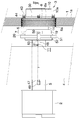
- FIG. 1 is a partially cutaway front view of a main part of a printing press showing an embodiment of the present invention.
- FIG. 2 is a plan view of FIG.
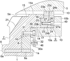
- FIG. 3 is an enlarged cross-sectional view taken along line III-III in FIG. 4 is a cross-sectional view taken along line IV-IV in FIG.
- FIG. 5 is an enlarged sectional view taken along line VV in FIG.
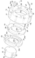
- FIG. 6 is an exploded perspective view of the main part of the plate cylinder driving device.
- FIG. 1 is a partially cutaway front view showing the main part of the printing press
- FIG. 2 is a plan view of the same.
- illustration of some members is omitted.
- the printing press has a plurality of plate cylinders (2) driven by one driving helical gear (1) which is a main gear.
- the driving helical gear (1) will be referred to as the first gear.
- a plurality of plate cylinder driving devices (3) are arranged around the first gear (1).
- the first gear (1) is rotatably supported by the frame (4) of the printing press and is driven to rotate about a horizontal axis by an appropriate driving means (not shown).
- the rotation direction of the first gear (1) is clockwise as shown by an arrow A in FIG. 1 and FIG. 4 described later.
- a plurality of teeth (1a) are formed obliquely with a predetermined twist angle.
- 3 to 6 show details of the plate cylinder driving device (3).
- the plate cylinder drive device (3) includes a plate cylinder drive shaft (5), a driven side gear member (7) having a driven side helical gear (6), and a helical gear for removing backlash.
- a rotation prevention member (9), a clamping member (10) constituting a rotation prevention member fixing means, and a position adjustment member (11) constituting a registration means are provided.
- the helical gear (6) on the driven side will be referred to as the second gear
- the helical gear (8) for removing the backlash will be referred to as the third gear.
- the plate cylinder drive shaft (5) is rotatably supported by the frame (4) so as to be parallel to the central axis of the first gear (1).
- the plate cylinder (2) is connected to the rear end portion of the drive shaft (5) protruding rearward from the frame (4), and rotates integrally with the drive shaft (5).
- FIG. 3 is a longitudinal sectional view (enlarged sectional view taken along the line III-III in FIG. 2) showing the overall configuration of the plate cylinder driving device (3)
- FIG. 4 is a partially cutaway front view of the plate cylinder driving device (3).
- FIG. 5 is a longitudinal sectional view showing an enlarged front part of the plate cylinder driving device (3) (enlarged sectional view taken along line VV in FIG. 4)
- FIG. 6 is an exploded perspective view showing the front portion of the plate cylinder drive shaft (5), the anti-rotation member (9), and the clamping member (10).
- an outward flange (12) is formed integrally with a portion near the front end of the plate cylinder drive shaft (5), and the outer diameter of the drive shaft (5) on the front side of the flange (12) is uniform.
- This portion is a connecting shaft portion (5a) connected to the driven gear member (7).
- Square spline grooves (13) extending in the front-rear direction are formed at a plurality of locations (four locations in this example) that equally divide the outer periphery of the connecting shaft portion (5a) in the circumferential direction.
- the spline groove (13) extends over the entire length of the connecting shaft portion (5a).
- the gear member (7) is attached around the connecting shaft portion (5a) so that it can rotate and move in the axial direction with respect to the connecting shaft portion (5a).
- the gear member (7) includes a boss portion (14) fitted around the drive shaft (5).
- An annular groove (15) is formed on the inner periphery of the boss portion (14), and the inner peripheral surface of the sliding contact portions (14a) and (14b) before and after the groove (15) is the outer peripheral surface of the connecting shaft portion (5a). It comes in sliding contact.
- the second gear (6) is integrally provided on the outer periphery of the intermediate portion in the axial direction of the boss portion (14).
- a portion of the boss portion (14) in front of the second gear (6) is a first fitting portion (16) having an outer diameter smaller than that of the second gear (6).
- the third gear (8) is fitted around the first fitting portion (16) so as to be rotatable and axially movable.
- a plurality of teeth (6a) and (8a) meshing with the teeth (1a) of the first gear (1) are formed on the outer circumferences of the second gear (6) and the third gear (8) obliquely with a predetermined twist angle.
- the second and third gears (6) and (8) are rotated counterclockwise by the first gear (1) as shown by an arrow B in FIGS. Details of the third gear (8) will be described later.
- the part of the boss part (14) in front of the first fitting part (16) is a second fitting part (17) having an outer diameter smaller than that of the first fitting part (16).
- the front end portion of the boss portion (14) in front of the second fitting portion (17) is a third fitting portion (18) having an outer diameter smaller than that of the second fitting portion (17).
- a cylindrical connecting portion (19) extending rearward is integrally formed on the outer periphery of the rear end of the boss portion (14).
- the connecting part (19) is concentric with the boss part (14), and the inner diameter of the connecting part (19) is larger than the outer diameter of the drive shaft (5).
- An outward flange (20) is integrally formed on the outer periphery of the connecting portion (19).
- a plurality of first oil supply holes (21) are formed at equal intervals in the circumferential direction in the boss portion (14) immediately after the second gear (6). Each first oil supply hole (21) passes through the boss portion (14) in the radial direction and communicates with the annular groove (15). Each first oil supply hole (21) is inclined rearward from the annular groove (15) toward the radially outer side.
- a plurality of second oil supply holes (22) are formed at equal intervals in the circumferential direction in a portion of the connecting portion (19) in front of the flange (20). Each second oil supply hole (22) penetrates the connecting portion (19) in the radial direction and reaches the inside of the connecting portion (19) immediately behind the boss portion (14).
- the detent member (9) includes two spline members (23) and (24) that are overlapped and fixed to each other so that the relative position in the circumferential direction can be adjusted. ing.
- the rear spline member (23) is referred to as a first spline member
- the front spline member (24) is referred to as a second spline member.
- Both spline members (23) and (24) form an annular shape having a relatively thick axial thickness.
- the inner diameters of both spline members (23) and (24) are slightly larger than the outer diameter of the drive shaft connecting shaft portion (5a).
- each spline member (23) (24) On the inner periphery of each spline member (23) (24), the same number of square spline teeth (23a) (24a) as the spline grooves (13) of the drive shaft (5) are formed integrally at equal intervals in the circumferential direction. ing.
- An annular first fitting portion (23b) protruding rearward is integrally formed on the outer peripheral side portion of the rear end surface of the first spline member (23).
- An annular second fitting portion (23c) projecting forward is formed integrally with a portion on the inner peripheral side of the front end surface of the first spline member (23).
- An annular fitting portion (24b) protruding rearward is integrally formed on the outer peripheral portion of the rear end surface of the second spline member (24).
- a plurality (four in this example) of screw holes (25) extending in the axial direction are formed at equal intervals in the circumferential direction in a portion near the outer periphery of the first spline member (23).
- a plurality of counterbore bolt holes (26) which are screw member insertion holes corresponding to the screw holes (25) of the first spline member (23) are formed in a penetrating manner in the portion near the outer periphery of the second spline member (24). Is formed.
- the fitting portion (24b) of the second spline member (24) is overlaid so as to be in close contact with the outer portion of the second fitting portion (23c) of the first spline member (23), and is passed through the bolt hole (26).
- Both the spline members (23) and (24) are fixed to each other by a hexagon socket head bolt (first bolt) (27) which is a screw member screwed into the screw hole (25).
- the first bolt (27) passed through the bolt hole (26) of the second spline member (24) is loosely fitted into the screw hole (25) of the first spline member (23), and both spline members (23) (24 ) Are close to each other, the head (27a) of the first bolt (27) is completely immersed in the bolt hole (26).
- both the spline members (23) and (24) are fixed as described above, the circumferential positions of the spline teeth (23a) and (24a) of both the spline members (23) and (24) are substantially the same.
- both the spline members (23) and (24) are fitted around the connecting shaft portion (5a) so that the spline teeth (23a) and (24a) fit into the spline groove (13), and the first spline member (23)
- the first fitting portion (23b) is fitted around the third fitting portion (18) of the boss portion (14).
- the inner diameter of the bolt hole (26) of the second spline member (24) is slightly larger than the outer diameter of the first bolt (27) (the outer diameter of the male thread). For this reason, the first bolt (27) passed through the bolt hole (26) of the second spline member (24) is loosely fitted into the screw hole (25) of the first spline member (23), and both spline members (23 ) (24) are close to each other, both spline members (23) (24) can be rotated to some extent relative to each other.
- the spline teeth (23a) and (24a) of both spline members (23) and (24) are adjusted by adjusting the relative positions in the circumferential direction of both spline members (23) and (24).
- the first bolt (27) is tightened with the two spline members (23), (24) being fixed.
- the pressure contact force of the spline teeth (23a) and (24a) to both side walls of the spline groove (13) is not backlash between the spline grooves (13) and the spline teeth (23a) (24a), but the spline groove ( 13)
- the size is such that the spline teeth (23a) and (24a) can move in the axial direction.
- a position adjusting circular hole (28) is formed in a penetrating manner at one position shifted in the circumferential direction from one bolt hole (26) of the second spline member (24).
- An annular spring support member (30) is fitted around the rear of the second fitting portion (17) of the boss portion (14) of the gear member (7), and a plurality of bolts (second bolts) (31) The boss portion (14) after the second fitting portion (17) is fixed in close contact with the forward-facing annular end surface.
- a plurality (four in this example) of convex portions (30a) are integrally formed at equal intervals in the circumferential direction.
- Each convex portion (30a) extends obliquely so as to face the radially outer side and the clockwise direction.
- a spring support hole (32) is formed in a portion near the tip of each convex portion (30a).
- the outer diameter of the spring support member (30) is slightly larger than that of the first fitting portion (16) of the boss portion (14), and the inner peripheral portion of the third gear (8) is connected to the spring support member (30) and the second It fits between the gears (6).
- a plurality of screw holes (first screw holes) (36) are formed on the annular end face of the boss portion (14) corresponding to these bolt holes (35).
- the clamping member (10) is formed by integrally forming an inward flange (flange portion) (10b) at the front end of a relatively thick cylindrical portion (10a).
- the rear portion of the cylindrical portion (10a) of the clamping member (10) is fitted around the second fitting portion (17) of the boss portion (14) on the front side of the spring support member (30), so that the cylindrical portion (10a)
- An anti-rotation member (9) is located inside, and the anti-rotation member (9) is sandwiched between the flange (10b) and the forward annular end surface behind the third fitting portion (18) of the boss portion (14).
- the cylindrical portion (10a) of the clamping member (10) has the same number of counterbore bolt holes (37), which are screw insertion holes corresponding to the eight bolt holes (35) of the spring support member (30). Is formed.
- the screw member is inserted into the bolt hole (37) of the clamping member (10) and the bolt hole (35) of the spring support member (30) and screwed into the female screw (36) of the boss portion (14).
- a plurality of hexagon socket head bolts (third bolts) (38) allow the detent member (9) to be between the flange (10b) and the forward annular end face after the third fitting part (18) of the boss part (14). It is pinched by.
- the gear member (7) rotates integrally with the drive shaft (5).
- bolt (38) comprises the rotation prevention member fixing means with the clamping member (10).
- One or more circular holes (39) for position adjustment are formed in the flange (10b) of the clamping member (10) so as to penetrate therethrough.
- four circular holes (39) are formed.
- the diameter of the circle passing through the center of these circular holes (39) is equal to the diameter of the circle passing through the center of the position adjusting circular hole (28) of the second spline member (24), and the circular hole ( The diameter of 39) is slightly larger than the diameter of the circular hole (28) of the second spline member (24).
- the same number of bolt tightening circular holes (40) as the bolt holes (26) of the second spline member (24) are formed in the flange (10b) of the clamping member (10) in a penetrating manner.
- the diameter of the circle passing through the center of these circular holes (40) is equal to the diameter of the circle passing through the center of the bolt hole (26) of the second spline member (24).
- the positional relationship in the circumferential direction of the two types of circular holes (39) and (40) of the flange (10b) is the same in the bolt hole (26) of the second spline member (24) and the circular hole for position adjustment (28). Same as the positional relationship, for adjusting the position of the clamping member (10) when the bolt tightening circular hole (40) of the clamping member (10) matches the bolt hole (26) of the second spline member (24)
- One of the circular holes (39) is adapted to match the position adjusting circular hole (28) of the second spline member (24).
- the third gear (8) has a plurality of (four in this example) bolt holes (41) which are threaded member insertion holes formed in a circumferential manner at equal intervals in the circumferential direction.
- a plurality of screw holes (second screw holes) (42) corresponding to these bolt holes (41) are formed in the second gear (6).
- a plurality of guide bolts (43) are passed through the bolt holes (41) of the third gear (8), and the rear part of the bolts (43) is screwed into the screw holes (42) of the second gear (6). Yes.
- These bolts (43) protrude forward from the third gear (8).
- the inner diameter of the bolt hole (41) is slightly larger than the outer diameter of the bolt (43) so that the third gear (8) can rotate a predetermined amount with respect to the second gear (6).
- the third gear (8) is urged backward to the second gear (6).
- a compression coil spring (first spring) (44) which is a first elastic member to be pressed is attached.
- the third gear (8) is screwed with a plurality of spring support pins (45) protruding forward at a predetermined distance clockwise from the convex portion (30a) of the spring support member (30).
- Both ends of the tension coil spring (second spring) (46) are fixed to the pin (45) and the hole (32) of the spring support member (30).
- the second spring (46) urges the third gear (8) counterclockwise (the rotation direction of the second gear (6)) relative to the second gear (6) and the first gear (1).
- the 2nd elastic member for removing the backlash between these is comprised.
- the position adjustment member (11) includes a screw shaft (47), a roller support shaft (48), an adjustment knob (49), and two front and rear rollers (50).
- the screw shaft (47) is disposed at the rear portion of the frame (4) and is fitted to a female screw member (not shown) provided on the frame (4).
- the knob (49) is fixed to the rear end of the screw shaft (47) protruding rearward of the frame (4).
- the roller support shaft (48) does not rotate at the front part of the frame (4) but is supported so as to move in the axial direction, and does not move in the axial direction at the front end part of the screw shaft (47) but can rotate. So that they are connected.
- the roller (50) is provided on the lower surface of the front portion of the support shaft (48) projecting forward from the frame (4) so as to freely rotate about an axis in the vertical direction (the radial direction of the drive shaft (5)). ing. Then, by rotating the adjustment knob (49), the roller (50) moves in the front-rear direction.
- a perforated disc-shaped flange member (51) is fitted around the rear portion of the connecting portion (19) of the gear member (7) from the flange (20).
- a disk-shaped fixing member (52) with a hole is fixed to the rear end surface of the connecting portion (19) by a plurality of bolts (53), and an inner peripheral portion of the flange member (51) is a flange (20) of the connecting portion (19). )
- the fixing member (52) The outer peripheral portion of the flange member (51) is sandwiched between the front and rear rollers (50) of the position adjusting member (11).
- the assembly and position adjustment of the plate cylinder driving device (3) is performed as follows, for example.
- the gear member (7) to which the third gear (8) is attached is fitted around the connecting shaft portion (5a), and the second and third gears (6) and (8) are engaged with the first gear (1). And the gear member (7) is coupled to the position adjusting member (11).
- two spline members (23) and (24) loosely connected by the first bolt (27) are fitted to the connecting shaft portion (5a), and the spline teeth (23a) (23a) ( Fit 24a) into the spline groove (13) of the shaft (5a).
- the clamping member (10) is fitted on the outer side of the anti-rotation member (9) and loosely connected to the gear member (7) by the third bolt (38).
- the plate cylinder driving device (3) is generally assembled.
- the eccentric shaft member (54) is formed by integrally and eccentrically forming a relatively short eccentric shaft portion (54b) having a smaller diameter on the front end surface (rear end surface in use) of the relatively long operation shaft portion (54a).
- a radial through hole (56) is formed in the base end side (front side in use) of the operation shaft (54a), and the operation rod (57) can be inserted into this hole (56).
- the outer diameter of the operation shaft portion (54a) is slightly smaller than the inner diameter of the position adjusting circular hole (28) of the second spline member (24), and the outer diameter of the eccentric shaft portion (54b) is smaller than that of the first spline member (23).
- the length of the eccentric shaft portion (54b) is substantially equal to the depth of the position adjusting slot (29) of the first spline member (23), and the length from the tip of the operating shaft portion (54a) to the hole (56).
- the thickness is larger than the sum of the thickness of the second spline member (24) and the thickness of the flange (10b) of the holding member (10).
- the eccentric shaft portion (54a) of the eccentric shaft member (54) is passed through the position adjusting circular hole (39) and the position adjusting circular hole (28) of the second spline member (24) to pass through the first spline member (23). Fit to the position adjustment slot (29).
- the operation shaft portion (54a) of the eccentric shaft member (54) is fitted into the circular holes (28) and (39), and the proximal end portion of the eccentric shaft portion (54) into which the operation rod (57) is inserted is the clamping member. (10) Since the projection protrudes outward, the operation shaft (54a) is rotated clockwise or counterclockwise by holding the operation rod (57) by hand.
- the eccentric shaft portion (54b) of the eccentric shaft member (54) moves in an arc shape around the central axis of the operation shaft portion (54a), so that both the spline members (23) and (24) are in the circumferential direction. Move to.
- the spline teeth (23a) and (24a) of both spline members (23) and (24) are pressed against both side walls of the spline groove (13) of the connecting shaft (5a) with an appropriate force, and backlash between them is eliminated. Then, the eccentric shaft member (54) is fixed at that position.
- Printing can be performed after the above rough registration has been completed, but by moving the position adjustment member (11) in the front-rear direction and moving the gear member (7) in the front-rear direction, fine registration is possible. Can do.
- the gear member (7) moves in the front-rear direction
- the second gear (6) moves in the front-rear direction with respect to the first gear (1), and the teeth of the first gear (1) and the second gear (6) ( The first gear (1) and the second gear (6) rotate relatively by the twist angle of 1a) and (6a).
- the rotational phases of the first gear (1) and the plate cylinder drive shaft (5) change, and fine registration is possible.
- the rotation of the first gear (1) is rotated via the second gear (6) and the gear member (7) and the rotation preventing member (9) are fixed to the gear member (7) as described above. It is transmitted to the plate cylinder drive shaft (5), and the plate cylinder (2) rotates.
- the second spring (46) urges the third gear (8) to rotate in the rotational direction with respect to the second gear (6). No backlash occurs between the third gears (6) and (8). Further, since the first spring (44) urges the third gear (8) toward the second gear (8) and presses it against one side of the second gear (6), the third gear (8) It does not tilt.
- oil is supplied to the inside of the gear member (7) from the two types of oil supply holes (21) and (22) of the gear member (7).
- the oil supplied from the first oil supply hole (21) enters the annular groove (15) of the boss part (14), and the sliding parts (14a) (14b) before and after the groove (15) and the connecting shaft part (5a )
- the oil supplied from the second oil supply hole (22) enters the gap between the sliding part (14b) on the rear side of the annular groove (15) and the connecting shaft part (5a). For this reason, a thin oil film is formed between the inner peripheral surface of the sliding portion (14a) (14b) of the boss portion (14) and the outer peripheral surface of the connecting shaft portion (5a), thereby the gear for the drive shaft (5).
- the member (7) is centered.
- the configurations of the printing press and the plate cylinder driving device (3) are not limited to those of the above-described embodiments, and can be changed as appropriate.
- the present invention is suitable for use in a plate cylinder driving device in a printing press.
- it is suitable for use in a plate cylinder driving device in a printing machine that performs multicolor printing on the outer peripheral surface of a beverage can.
- the plate cylinder driving device according to the present invention it is possible to eliminate the backlash of the helical gear on the driving side and the helical gear on the driven side, smooth the rotation of the driven gear member, and improve the rotation accuracy of the plate cylinder. This can improve the quality of printing.
Landscapes
- Engineering & Computer Science (AREA)
- Mechanical Engineering (AREA)
- General Engineering & Computer Science (AREA)
- Gears, Cams (AREA)
- Rotary Presses (AREA)
Abstract
Description
(2) 版胴
(3) 版胴駆動装置
(4) フレーム
(5) 版胴駆動軸
(6) 従動側はすば歯車
(7) 従動側歯車部材
(8) バックラッシ除去用はすば歯車
(9) 回り止め部材
(10) 回り止め部材挟持部材
(10a) 円筒部
(10b) フランジ部
(11) 従動側歯車部材位置調整部材
(13) スプラインみぞ
(23) 第1スプライン部材
(23a) スプライン歯
(24) 第2スプライン部材
(24a) スプライン歯
(25) めねじ
(26) ボルト穴(ねじ穴)
(27) 六角穴付きボルト(ねじ部材)
(28) 円形穴
(29) 長穴
(38) ボルト(ねじ部材)
(39) スプライン部材調整用貫通穴
(40) ボルト締め付け用貫通穴
(44) 第1のコイルばね(弾性部材)
(46) 第2のコイルばね(弾性部材)
Claims (6)
- 印刷機における駆動側はすば歯車の回転を版胴に伝達して版胴を回転駆動する装置であって、
印刷機のフレームに回転支持されるとともに版胴に連結されて版胴と一体に回転する版胴駆動軸と、
駆動側はすば歯車とかみ合う従動側はすば歯車を有し版胴駆動軸に対して回転および軸方向の移動ができるように版胴駆動軸の周囲に取り付けられた従動側歯車部材と、
版胴駆動軸に対して従動側歯車部材を軸方向に移動させて所定位置に固定する見当合わせ手段と、
版胴駆動軸に対して回転はしないが軸方向の移動ができるように版胴駆動軸に取り付けられた回り止め部材と、
回り止め部材を従動側歯車部材に着脱可能に固定する回り止め部材固定手段と、
従動側はすば歯車に対して所定範囲の回転および軸方向の移動ができるように従動側はすば歯車の片面に配置されたバックラッシ除去用はすば歯車と、
バックラッシ除去用はすば歯車を従動側はすば歯車側に付勢して従動側はすば歯車の片面に圧接させる第1の弾性部材と、
バックラッシ除去用はすば歯車を従動側はすば歯車に対して所定方向に回転するように付勢する第2の弾性部材とを備えていることを特徴とする印刷機における版胴駆動装置。 - 回り止め部材固定手段が、従動側歯車部材との間に回り止め部材を挟む挟持部材と、挟持部材を従動側歯車部材に固定して両者間に回り止め部材を挟み止めるねじ部材とを備えており、挟持部材が、回り止め部材の周囲に位置する円筒部の一端に、従動側歯車部材との間に回り止め部材を挟むフランジ部が一体に形成されたものであり、挟持部材の円筒部がねじ部材により従動側歯車部材に固定されるようになされていることを特徴とする請求項1の印刷機における版胴駆動装置。
- 回り止め部材が、周方向の相対位置の調整ができるように重ねられて互いに固定された2つの環状スプライン部材を備えており、各スプライン部材が、版胴駆動軸の外周に形成されたスプラインみぞにはまるスプライン歯を内周に有するものであることを特徴とする請求項1または2の印刷機における版胴駆動装置。
- 第1のスプライン部材にねじ部材がねじはめられる複数のねじ穴が形成され、第2のスプライン部材にねじ部材のおねじ部の外径より内径の大きい複数のねじ挿通穴が形成されており、複数のねじ部材がねじ挿通穴に通されてねじ穴にねじはめられることにより2つのスプライン部材が互いに固定されていることを特徴とする請求項3の印刷機における版胴駆動装置。
- 第2のスプライン部材に、これを軸方向に貫通する位置調整用円形穴が貫通状に形成され、この円形穴に対向する第1のスプライン部材の面に、周方向の幅が円形穴の内径より小さくて径方向の長さがこの幅より大きい位置調整用長穴が形成されていることを特徴とする請求項4の印刷機における版胴駆動装置。
- 回り止め部材の2つのスプライン部材を固定するためのねじ部材が六角穴付きボルトであり、挟持部材のフランジ部に、第2のスプライン部材の位置調整用円形穴に対応する1つ以上の位置調整用円形穴と、この位置調整用円形穴が第2のスプライン部材の位置調整用円形穴に合致したときに第2スプライン部材の複数のねじ挿通穴に対応する複数のボルト締め付け用円形穴とが貫通状に設けられていることを特徴とする請求項5の印刷機における版胴駆動装置。
Priority Applications (7)
| Application Number | Priority Date | Filing Date | Title |
|---|---|---|---|
| KR1020137024620A KR101890002B1 (ko) | 2011-02-15 | 2011-02-15 | 인쇄기에 있어서의 판동 구동 장치 |
| EP11858765.8A EP2676796B1 (en) | 2011-02-15 | 2011-02-15 | Plate cylinder drive device in printing machine |
| CN201180070117.1A CN103619592B (zh) | 2011-02-15 | 2011-02-15 | 印刷机的印版滚筒驱动装置 |
| US14/005,626 US9086137B2 (en) | 2011-02-15 | 2011-02-15 | Plate cylinder drive unit in printer |
| ES11858765.8T ES2655944T3 (es) | 2011-02-15 | 2011-02-15 | Dispositivo de accionamiento del cilindro portaplaca de impresora |
| JP2011524086A JP5401548B2 (ja) | 2011-02-15 | 2011-02-15 | 印刷機における版胴駆動装置 |
| PCT/JP2011/053143 WO2012111091A1 (ja) | 2011-02-15 | 2011-02-15 | 印刷機における版胴駆動装置 |
Applications Claiming Priority (1)
| Application Number | Priority Date | Filing Date | Title |
|---|---|---|---|
| PCT/JP2011/053143 WO2012111091A1 (ja) | 2011-02-15 | 2011-02-15 | 印刷機における版胴駆動装置 |
Publications (1)
| Publication Number | Publication Date |
|---|---|
| WO2012111091A1 true WO2012111091A1 (ja) | 2012-08-23 |
Family
ID=46672056
Family Applications (1)
| Application Number | Title | Priority Date | Filing Date |
|---|---|---|---|
| PCT/JP2011/053143 Ceased WO2012111091A1 (ja) | 2011-02-15 | 2011-02-15 | 印刷機における版胴駆動装置 |
Country Status (7)
| Country | Link |
|---|---|
| US (1) | US9086137B2 (ja) |
| EP (1) | EP2676796B1 (ja) |
| JP (1) | JP5401548B2 (ja) |
| KR (1) | KR101890002B1 (ja) |
| CN (1) | CN103619592B (ja) |
| ES (1) | ES2655944T3 (ja) |
| WO (1) | WO2012111091A1 (ja) |
Cited By (4)
| Publication number | Priority date | Publication date | Assignee | Title |
|---|---|---|---|---|
| CN104343932A (zh) * | 2014-09-28 | 2015-02-11 | 温州职业技术学院 | 圆柱齿轮齿侧间隙双螺杆调整装置 |
| WO2018008344A1 (ja) * | 2016-07-04 | 2018-01-11 | アイマー・プランニング株式会社 | 版胴駆動装置を備える印刷機 |
| CN112504883A (zh) * | 2020-11-26 | 2021-03-16 | 明锦(天津)数码科技有限公司 | 一种电动车电池抗穿刺检测试验机 |
| CN115247690A (zh) * | 2021-04-26 | 2022-10-28 | 财团法人工业技术研究院 | 主轴驱动装置 |
Families Citing this family (5)
| Publication number | Priority date | Publication date | Assignee | Title |
|---|---|---|---|---|
| US9618108B2 (en) * | 2013-07-17 | 2017-04-11 | Achates Power, Inc. | Gear noise reduction in opposed-piston engines |
| CN105042035A (zh) * | 2015-07-23 | 2015-11-11 | 深圳市科发机械制造有限公司 | 齿轮啮合间歇可调结构 |
| CN105202153A (zh) * | 2015-11-03 | 2015-12-30 | 成都埃森普特科技股份有限公司 | 焊接机械手水平转枪机构无间隙齿轮及输出传动装置 |
| DE102017126205A1 (de) * | 2017-11-09 | 2019-05-09 | Man Truck & Bus Ag | Zahnrad, insbesondere Zwischenrad, für einen Rädertrieb |
| CN112240377B (zh) * | 2020-10-27 | 2025-06-20 | 山东陆达机械设备有限公司 | 一种用于螺旋锥齿轮的驱动装置 |
Citations (6)
| Publication number | Priority date | Publication date | Assignee | Title |
|---|---|---|---|---|
| JPH06126927A (ja) * | 1992-10-20 | 1994-05-10 | Mitsubishi Heavy Ind Ltd | 天地見当合せ装置 |
| JPH08300606A (ja) * | 1995-05-05 | 1996-11-19 | Heidelberger Druckmas Ag | 輪転印刷機の胴の横方向及び周方向の位置を調節する装置 |
| JPH0939196A (ja) * | 1995-07-27 | 1997-02-10 | Mitsubishi Heavy Ind Ltd | 輪転印刷機の分割版胴装置 |
| JPH10309792A (ja) * | 1997-04-30 | 1998-11-24 | Man Roland Druckmas Ag | 二重歯車を可脱に連結する装置 |
| JP2002188708A (ja) * | 2000-12-21 | 2002-07-05 | Lintec Corp | 歯車機構および印刷装置 |
| JP2007021858A (ja) * | 2005-07-15 | 2007-02-01 | Komori Corp | 移動型インキユニットを備えた印刷機 |
Family Cites Families (11)
| Publication number | Priority date | Publication date | Assignee | Title |
|---|---|---|---|---|
| US2030028A (en) * | 1935-02-13 | 1936-02-04 | F X Hooper Company Inc | Shaft adjusting means |
| US2181895A (en) * | 1937-09-10 | 1939-12-05 | Hoe & Co R | Registering mechanism for printing cylinders |
| US3505953A (en) * | 1966-12-10 | 1970-04-14 | Koenig & Bauer Schnellpressfab | Mechanism for adjusting the lateral and peripheral register of a rotary printing press |
| CS160029B1 (ja) * | 1973-01-26 | 1975-02-28 | ||
| US4006685A (en) * | 1975-09-22 | 1977-02-08 | Miller Printing Machinery Co. | Axial and circumferential register control apparatus for a cylinder in a press frame |
| DE2705522C3 (de) * | 1977-02-10 | 1980-10-09 | Heidelberger Druckmaschinen Ag, 6900 Heidelberg | Vorrichtung zum Einstellen des Umfangs- und Seitenregisters an Rotationsdruckmaschinen |
| US4663981A (en) * | 1983-05-26 | 1987-05-12 | Guy Louradour | Antivibration system for a mechanical transmissions |
| US5813335A (en) * | 1996-12-18 | 1998-09-29 | Heidelberg Harris Inc. | Apparatus for preventing backlash between the meshing teeth of a first and a second gear in a printing unit of a lithographic rotary printing press |
| CN2721391Y (zh) * | 2004-08-30 | 2005-08-31 | 马洪镇 | 一种胶印机印刷传动机构 |
| JP2010167617A (ja) * | 2009-01-21 | 2010-08-05 | Mitsubishi Heavy Ind Ltd | 印刷機の見当装置 |
| CN201471821U (zh) * | 2009-07-31 | 2010-05-19 | 江苏昌昇集团股份有限公司 | 一种胶印机齿轮侧隙调整机构 |
-
2011
- 2011-02-15 ES ES11858765.8T patent/ES2655944T3/es active Active
- 2011-02-15 KR KR1020137024620A patent/KR101890002B1/ko active Active
- 2011-02-15 WO PCT/JP2011/053143 patent/WO2012111091A1/ja not_active Ceased
- 2011-02-15 JP JP2011524086A patent/JP5401548B2/ja active Active
- 2011-02-15 US US14/005,626 patent/US9086137B2/en active Active
- 2011-02-15 EP EP11858765.8A patent/EP2676796B1/en active Active
- 2011-02-15 CN CN201180070117.1A patent/CN103619592B/zh active Active
Patent Citations (6)
| Publication number | Priority date | Publication date | Assignee | Title |
|---|---|---|---|---|
| JPH06126927A (ja) * | 1992-10-20 | 1994-05-10 | Mitsubishi Heavy Ind Ltd | 天地見当合せ装置 |
| JPH08300606A (ja) * | 1995-05-05 | 1996-11-19 | Heidelberger Druckmas Ag | 輪転印刷機の胴の横方向及び周方向の位置を調節する装置 |
| JPH0939196A (ja) * | 1995-07-27 | 1997-02-10 | Mitsubishi Heavy Ind Ltd | 輪転印刷機の分割版胴装置 |
| JPH10309792A (ja) * | 1997-04-30 | 1998-11-24 | Man Roland Druckmas Ag | 二重歯車を可脱に連結する装置 |
| JP2002188708A (ja) * | 2000-12-21 | 2002-07-05 | Lintec Corp | 歯車機構および印刷装置 |
| JP2007021858A (ja) * | 2005-07-15 | 2007-02-01 | Komori Corp | 移動型インキユニットを備えた印刷機 |
Cited By (5)
| Publication number | Priority date | Publication date | Assignee | Title |
|---|---|---|---|---|
| CN104343932A (zh) * | 2014-09-28 | 2015-02-11 | 温州职业技术学院 | 圆柱齿轮齿侧间隙双螺杆调整装置 |
| WO2018008344A1 (ja) * | 2016-07-04 | 2018-01-11 | アイマー・プランニング株式会社 | 版胴駆動装置を備える印刷機 |
| US11046067B2 (en) | 2016-07-04 | 2021-06-29 | I.Mer Co., Ltd. | Printing machine provided with plate cylinder driving device |
| CN112504883A (zh) * | 2020-11-26 | 2021-03-16 | 明锦(天津)数码科技有限公司 | 一种电动车电池抗穿刺检测试验机 |
| CN115247690A (zh) * | 2021-04-26 | 2022-10-28 | 财团法人工业技术研究院 | 主轴驱动装置 |
Also Published As
| Publication number | Publication date |
|---|---|
| JP5401548B2 (ja) | 2014-01-29 |
| KR20140020929A (ko) | 2014-02-19 |
| CN103619592A (zh) | 2014-03-05 |
| EP2676796A1 (en) | 2013-12-25 |
| EP2676796B1 (en) | 2017-11-08 |
| KR101890002B1 (ko) | 2018-08-20 |
| US9086137B2 (en) | 2015-07-21 |
| CN103619592B (zh) | 2015-11-25 |
| JPWO2012111091A1 (ja) | 2014-07-03 |
| US20140123795A1 (en) | 2014-05-08 |
| EP2676796A4 (en) | 2015-08-05 |
| ES2655944T3 (es) | 2018-02-22 |
Similar Documents
| Publication | Publication Date | Title |
|---|---|---|
| JP5401548B2 (ja) | 印刷機における版胴駆動装置 | |
| JP5691793B2 (ja) | シートリクライニング装置 | |
| CN104797364B (zh) | 用于管道加工设备的轴承组件 | |
| EP0407686B2 (en) | Horizontal perforation forming apparatus for rotary press | |
| US5964150A (en) | Couple of gear wheels for driving printing drum with means for mutual phase restoration | |
| JP2006106403A (ja) | ロック機構付きレンズ鏡筒 | |
| EP2700504A2 (en) | Adjustable form roll apparatus | |
| JP2002188708A (ja) | 歯車機構および印刷装置 | |
| JP2010058589A (ja) | 自転車用ギアクランク | |
| KR20130128817A (ko) | 웜 기어의 백래시 조절장치 | |
| KR20170050973A (ko) | 전조장치 | |
| JP2013002606A (ja) | 歯車装置 | |
| JP2961425B2 (ja) | 輪転印刷機の横ミシン目加工装置 | |
| JP2012172813A (ja) | 回転ギヤのピッチ調整機構及びピッチ調整方法 | |
| JP3580578B2 (ja) | ねじ転造用ダイヘッドの微調整機構 | |
| JP4820803B2 (ja) | オフセット印刷機 | |
| JPS60259445A (ja) | 輪転印刷機における版胴駆動装置 | |
| JP3577634B2 (ja) | 版胴装置 | |
| JP4555708B2 (ja) | ローラーガイド装置 | |
| JPH02217248A (ja) | オフセット印刷機の胴を駆動するための歯車 | |
| JPH0724368Y2 (ja) | 輪転機の折畳装置用折りローラ | |
| JP2004268749A (ja) | ラックアンドピニオン式ステアリングギヤ装置 | |
| CN107405741A (zh) | 用于管道加工设备的轴承组件 | |
| JP6649027B2 (ja) | スイングアームの支持構造 | |
| JP2023111660A (ja) | 駆動装置及び画像形成装置 |
Legal Events
| Date | Code | Title | Description |
|---|---|---|---|
| WWE | Wipo information: entry into national phase |
Ref document number: 2011524086 Country of ref document: JP |
|
| 121 | Ep: the epo has been informed by wipo that ep was designated in this application |
Ref document number: 11858765 Country of ref document: EP Kind code of ref document: A1 |
|
| NENP | Non-entry into the national phase |
Ref country code: DE |
|
| ENP | Entry into the national phase |
Ref document number: 20137024620 Country of ref document: KR Kind code of ref document: A |
|
| REEP | Request for entry into the european phase |
Ref document number: 2011858765 Country of ref document: EP |
|
| WWE | Wipo information: entry into national phase |
Ref document number: 2011858765 Country of ref document: EP |
|
| WWE | Wipo information: entry into national phase |
Ref document number: 14005626 Country of ref document: US |