WO2012111222A1 - ネットワークシステム、及びネットワークフロー追跡方法 - Google Patents
ネットワークシステム、及びネットワークフロー追跡方法 Download PDFInfo
- Publication number
- WO2012111222A1 WO2012111222A1 PCT/JP2011/078439 JP2011078439W WO2012111222A1 WO 2012111222 A1 WO2012111222 A1 WO 2012111222A1 JP 2011078439 W JP2011078439 W JP 2011078439W WO 2012111222 A1 WO2012111222 A1 WO 2012111222A1
- Authority
- WO
- WIPO (PCT)
- Prior art keywords
- packet
- header
- switch
- function
- conversion
- Prior art date
- Legal status (The legal status is an assumption and is not a legal conclusion. Google has not performed a legal analysis and makes no representation as to the accuracy of the status listed.)
- Ceased
Links
Images

Classifications
-
- H—ELECTRICITY
- H04—ELECTRIC COMMUNICATION TECHNIQUE
- H04L—TRANSMISSION OF DIGITAL INFORMATION, e.g. TELEGRAPHIC COMMUNICATION
- H04L43/00—Arrangements for monitoring or testing data switching networks
- H04L43/20—Arrangements for monitoring or testing data switching networks the monitoring system or the monitored elements being virtualised, abstracted or software-defined entities, e.g. SDN or NFV
-
- H—ELECTRICITY
- H04—ELECTRIC COMMUNICATION TECHNIQUE
- H04L—TRANSMISSION OF DIGITAL INFORMATION, e.g. TELEGRAPHIC COMMUNICATION
- H04L12/00—Data switching networks
- H04L12/28—Data switching networks characterised by path configuration, e.g. LAN [Local Area Networks] or WAN [Wide Area Networks]
- H04L12/40—Bus networks
- H04L12/407—Bus networks with decentralised control
- H04L12/413—Bus networks with decentralised control with random access, e.g. carrier-sense multiple-access with collision detection [CSMA-CD]
-
- H—ELECTRICITY
- H04—ELECTRIC COMMUNICATION TECHNIQUE
- H04L—TRANSMISSION OF DIGITAL INFORMATION, e.g. TELEGRAPHIC COMMUNICATION
- H04L12/00—Data switching networks
- H04L12/28—Data switching networks characterised by path configuration, e.g. LAN [Local Area Networks] or WAN [Wide Area Networks]
- H04L12/46—Interconnection of networks
- H04L12/4633—Interconnection of networks using encapsulation techniques, e.g. tunneling
-
- H—ELECTRICITY
- H04—ELECTRIC COMMUNICATION TECHNIQUE
- H04L—TRANSMISSION OF DIGITAL INFORMATION, e.g. TELEGRAPHIC COMMUNICATION
- H04L43/00—Arrangements for monitoring or testing data switching networks
- H04L43/02—Capturing of monitoring data
- H04L43/026—Capturing of monitoring data using flow identification
-
- H—ELECTRICITY
- H04—ELECTRIC COMMUNICATION TECHNIQUE
- H04L—TRANSMISSION OF DIGITAL INFORMATION, e.g. TELEGRAPHIC COMMUNICATION
- H04L49/00—Packet switching elements
- H04L49/30—Peripheral units, e.g. input or output ports
- H04L49/3009—Header conversion, routing tables or routing tags
-
- H—ELECTRICITY
- H04—ELECTRIC COMMUNICATION TECHNIQUE
- H04L—TRANSMISSION OF DIGITAL INFORMATION, e.g. TELEGRAPHIC COMMUNICATION
- H04L69/00—Network arrangements, protocols or services independent of the application payload and not provided for in the other groups of this subclass
- H04L69/22—Parsing or analysis of headers
Definitions
- the present invention relates to a network system, and more particularly to a network flow tracking method in a network system.
- CU control plane / U: user plane
- control plane control plane
- OpenFlow open flow
- a controller such as OFC (OpenFlow Controller) controls the behavior of the switch by operating a flow table of the switch such as OFS (OpenFlow Switch).
- OFC OpenFlow Controller
- the controller and the switch are connected by a secure channel.
- the switches in the OpenFlow network system are edge switches and core switches that form an OpenFlow network and are under the control of the controller.
- a series of packet flows from reception of a packet at the input side edge switch to transmission at the output side edge switch in the OpenFlow network is called a flow.
- the packet may be read as a frame.
- the difference between a packet and a frame is only the difference in the data unit (PDU: Protocol Data Unit) handled by the protocol.
- the packet is a PDU of “TCP / IP” (Transmission Control Protocol / Internet Protocol).
- the frame is a PDU of “Ethernet (registered trademark)”.
- the flow table is a table in which a flow entry (Flow entry) defining a predetermined operation (action) to be performed on a packet (communication data) that meets a predetermined matching condition (rule) is registered.
- Flow entry a flow entry defining a predetermined operation (action) to be performed on a packet (communication data) that meets a predetermined matching condition (rule) is registered.
- the rule of the flow entry is one of a destination address (Destination Address), a source address (Source Address), a destination port (Destination Port), a source port (Source Port) included in the header area of each protocol layer of the packet, or Defined and distinguishable by various combinations using all.
- the above address includes a MAC address (Media Access Control Address) and an IP address (Internet Protocol Address).
- information on the ingress port (Ingress Port) can also be used as a rule for the flow entry.
- a part (or all) of the header area value of the packet indicating the flow can be set by a regular expression, a wild card “*”, or the like.
- the actions of the flow entry are operations such as “output to a specific port”, “discard”, and “rewrite header”. For example, if the identification information (output port number, etc.) of the output port is indicated in the action of the flow entry, the switch outputs a packet to the corresponding port, and if the identification information of the output port is not indicated , Discard the packet. Alternatively, if the header information is indicated in the action of the flow entry, the switch rewrites the header of the packet based on the header information.
- the switch in the OpenFlow network system executes a flow entry action on a packet group (packet sequence) that conforms to the flow entry rules.
- a packet group (packet sequence) that matches a flow entry rule (a predetermined header condition or the like) is handled as a flow.
- a flow entry rule a predetermined header condition or the like
- the current network has a very complicated configuration, and devices with various functions such as a firewall and a load balancer (load balancer) are placed in front of the server and client machine. And these devices can lose the benefits of flow-based network control.
- load balancer load balancer
- a device having a function of NAT (Network Address Translation) or NAPT (Network Address Port Translation) performs packet header conversion. For example, a device having a NAT function rewrites an IP header, and a device having a NAPT function also rewrites an IP header and a layer 4 header.
- NAT Network Address Translation
- NAPT Network Address Port Translation
- the packet header When passing through such a device (hereinafter referred to as a header conversion device), the packet header is converted, so that the flow before passing and the flow after passing become different flows.
- a header conversion device When passing through such a device (hereinafter referred to as a header conversion device), the packet header is converted, so that the flow before passing and the flow after passing become different flows.
- the header conversion device inquired, the address conversion table is referred to, the packet header information before conversion is acquired from the converted packet header information, and the corresponding flow is found.
- such a method can be realized only when the header conversion device has an interface that can be inquired from the outside of the device and can refer to the information of the address conversion table. If such conditions are not met, it is necessary to modify the header conversion device so that the conditions are met.
- Patent Document 1 Japanese Patent Laid-Open No. 2005-210518 discloses a source tracking information providing device and a source tracking device which are devices that perform IP traceback.
- IP traceback Internet Control Message Protocol Traceback
- ICMP traceback Internet Control Message Protocol Traceback
- ICMP traceback is a method in which a router device on an intermediate path selects an IP packet to be tracked with a certain probability, generates tracking information for the IP packet, transmits the tracking information to an IP packet destination in an ICMP message, and The destination device displays this tracking information.
- An object of the present invention is to encapsulate a packet with the same header as the current header at the switch, and after passing through the network appliance, two types of headers before and after conversion are attached to the packet. It is to provide a network system and a network flow tracking method to be in a state.
- the header includes all headers from layer 2 to layer 4. Specifically, the header is read as “all or a part of information that can be a rule of a flow entry”.
- the network system has a switch having a function of processing a received packet in accordance with the contents of a set flow table entry (flow entry), receives a packet inquiry from the switch, and controls the packet uniformly.
- a controller having a function for setting an entry in which the rules and operations of the switch are defined in the flow table of the switch, and a packet received from at least one of the switch and the controller, and using the same header as the packet header
- an encapsulation module having a function of encapsulating.
- a computer is a computer having a function as an encapsulation module, and a switch having a function of processing a received packet according to the contents of a set flow table entry, receives a packet inquiry from the switch, A controller having a function of setting an entry in which a rule and an operation for uniformly controlling the packet are defined in a flow table of the switch, a device receiving the packet from at least one of the controller, and the packet And a device for encapsulating the packet using the same header as the packet header.
- the switch processes the received packet in accordance with the contents of the set flow table entry.
- the controller receives a packet inquiry from the switch, and sets an entry in which rules and operations for uniformly controlling the packet are defined in the flow table of the switch.
- the encapsulation module receives a packet from at least one of the switch and the controller, and encapsulates the packet using the same header as the packet header.
- a program according to the present invention is a program executed by a computer having a function as an encapsulation module, and has a function of processing a received packet according to the contents of a set flow table entry, and a packet from the switch.
- the program according to the present invention can be stored in a storage device or a storage medium.
- the present invention is directed to a CU separation type network system.
- an OpenFlow network system which is one of CU separation type network systems, will be described as an example. However, actually, it is not limited to the open flow network system.
- Each of the switches 20 (20-i, i 1 to n) transfers the received packet according to the entry registered in its own flow table.
- a virtual switch is a switch realized by a virtual machine operating on a physical machine.
- the header conversion device 30 converts the header information of the packet received from the predetermined switch 20 and transfers it to the other switch 20.
- a computer such as a PC (personal computer), an appliance, a thin client terminal / server, a workstation, a mainframe, and a supercomputer is assumed.
- the controller 10 may be an expansion board mounted on a computer or a virtual machine (Virtual Machine (VM)) constructed on a physical machine.
- VM Virtual Machine
- the physical machine in which the controller 10, the switch 20 (20-i, i 1 to n) operates, and the header conversion device 30 are driven based on a program and execute a predetermined process, the program and various data
- a memory to be stored and a communication interface for connecting to a network.
- processors include a CPU (Central Processing Unit), a network processor (NP: Network Processor), a microprocessor (microprocessor), a microcontroller (microcontroller), or a semiconductor integrated circuit (LSI: Large Scale) having a dedicated function. Integration) or the like.
- CPU Central Processing Unit
- NP Network Processor
- microprocessor microprocessor
- microcontroller microcontroller
- LSI semiconductor integrated circuit
- semiconductor storage devices such as RAM (Random Access Memory), ROM (Read Only Memory), EEPROM (Electrically Erasable and Programmable Read Only Memory), and HDD Memory (SDHidK)
- RAM Random Access Memory
- ROM Read Only Memory
- EEPROM Electrical Erasable and Programmable Read Only Memory
- HDD Memory HDD Memory
- An auxiliary storage device such as State Drive
- a removable disk such as a DVD (Digital Versatile Disk)
- a storage medium such as an SD memory card (Secure Digital memory card), or the like is conceivable.
- processor and the memory may be integrated.
- a single chip such as a microcomputer has been developed. Therefore, a case where a one-chip microcomputer mounted on a computer or the like includes a processor and a memory can be considered.
- Examples of the above communication interfaces include semiconductor integrated circuits such as boards (motherboards, I / O boards) and chips that support network communication, network adapters such as NIC (Network Interface Card), similar expansion cards, antennas, etc. Communication ports such as communication devices and connection ports (connectors) are conceivable.
- networks include the Internet, LAN (Local Area Network), wireless LAN (Wireless LAN), WAN (Wide Area Network), backbone (Backbone), cable TV (CATV) line, fixed telephone network, mobile phone network, WiMAX (IEEE 802.16a), 3G (3rd Generation), dedicated line (lease line), IrDA (Infrared Data Association), Bluetooth (registered trademark), serial communication line, data bus, and the like are conceivable.
- the controller 10 sets in advance so as to “encapsulate a packet related to a predetermined flow” in the encapsulation module 21-1 of the switch 20-1.
- the controller 10 previously copies (copies) the IP header of the packet relating to the predetermined flow to the encapsulation module 21-1 of the switch 20-1, and uses the same header as the IP header. It is set so that the packet is encapsulated and the encapsulated packet is transferred.
- the IP header is described as an example, but the IP header is only an example of the header. Actually, not only the layer 3 IP header but also all headers from layer 2 to layer 4 may be targeted. Specifically, “IP header” is read as “all or part of information that can be a rule of a flow entry”.
- the controller 10 sends, in advance, to the encapsulation module 21-2 of the switch 20-2, “a pair (set) of a header before conversion and a header after conversion as header conversion information to the controller and a received packet
- the processing is set such that if there is a post-conversion header in the received packet, the post-conversion header is replaced if there is a pre-conversion header. It may be set such that “after removing all the headers from the received packet, the process of adding only the header after conversion is performed”. Alternatively, it may be set such that “if the received packet has a second-stage header (pre-conversion header), a process for removing it is performed”.
- the switch 20-1 passes the input packet to the encapsulation module 21-1.
- the configuration of the input packet is “IP header 1 ⁇ payload”.
- the encapsulation module 21-1 duplicates the IP header 1 of the packet as set by the controller 10, encapsulates the packet with the same header as the IP header 1, and transfers the packet. That is, in the packet to be transferred, the IP header 1 is added to the payload in duplicate (two stages). Therefore, the configuration of the packet transferred from the switch 20-1 is “IP header 1 ⁇ IP header 1 ⁇ payload”.
- the first “IP header 1” portion becomes the IP header of the encapsulated packet
- the remaining “IP header 1 -payload” portion originally Packet
- GRE Generic Routing Encapsulation
- the header conversion device 30 refers to the IP header 1 of the input packet, performs address conversion processing, and converts the IP header 1 into the IP header 2.
- the header conversion apparatus 30 uses the IP header 1 as the global address as the transmission destination IP address.
- the IP header 2 of “10.0.0.10” is converted.
- the header conversion device 30 converts the IP header 1 of the input packet into the IP header 2 having a different value, and transfers the packet.
- the header conversion device 30 removes / converts the top one of the IP headers 1 assigned in duplicate (two stages), and instead attaches the IP header 2 to the payload, and then forwards the packet. To do. Therefore, the configuration of the transferred packet is “IP header 2 -IP header 1 -payload”.
- the header conversion device 30 receives the encapsulated packet from the switch 20-1, among the “IP header 1-IP header 1-payload”, the header “IP header 1” is the IP header of the encapsulated packet. The part of “IP header 1” is converted to “IP header 2”.
- the first “IP header 2” portion becomes the IP header of the packet to be transferred
- the remaining “IP header 1 -payload” portion original Packet
- the switch 20-2 passes the input packet to the encapsulation module 21-2.
- the encapsulation module 21-2 transmits “a pair (set) of the header before conversion and the header after conversion to the controller as header conversion information, and removes the header after conversion if there is a header after conversion. Then, if there is a pre-conversion header, a process of replacing it with a post-conversion header is performed ”. Alternatively, it may be set such that “after removing all the headers from the received packet, the process of adding only the converted header is performed”. Alternatively, it may be set such that “if the received packet has a second-stage header (pre-conversion header), a process for removing it is performed”.
- the encapsulation module 21-2 confirms whether the input packet is an encapsulated packet, and if it is an encapsulated packet, of the “IP header 2—IP header 1—payload” With reference to the IP header 2 and the IP header 1, header conversion information is created based on these pairs, and transmitted to the controller 10.
- the header conversion information is information indicating that “the source IP address“ 192.168.0.10 ”has been converted to“ 10.0.0.10. ””.
- the encapsulation module 21-2 removes the leading IP header 2 from the “IP header 2 -IP header 1 -payload” and releases the remaining “IP header” in order to release the encapsulation of the input packet.
- IP header 1 is replaced with “IP header 2”.
- the encapsulation module 21-2 removes the IP header 1 from the original packet and adds the IP header 2 to the payload, and then transfers the packet. Therefore, the configuration of the transferred packet is “IP header 2 ⁇ payload”.
- the controller 10 can acquire header conversion information without any improvement or change in the header conversion device 30, and the flow can be traced using the information.
- FIG. 1 it is assumed that the controller 10 is linked or integrated with the encapsulation module 21-1 and the encapsulation module 21-2.
- the switch 20-1 transmits the “reception packet” to the controller 10 and receives the “encapsulated packet” from the controller 10 as a response.
- IP header in the description of the present invention is read as “all or part of information that can be a rule of a flow entry”.
- Step S101 The encapsulation module 21-1 receives the packet.
- the configuration of the received packet is “IP header 1—payload”.
- Step S102 the encapsulation module 21-1 checks whether the received packet is a packet to be encapsulated.
- Step S103 If the packet is to be encapsulated, the encapsulation module 21-1 refers to the IP header 1, duplicates the IP header 1, and performs encapsulation with the same IP header 1. In this case, the packet configuration is “IP header 1 -IP header 1 -payload”.
- Step S104 The encapsulation module 21-1 transfers the packet via the switch 20-1.
- the packet configuration is “IP header 1 -IP header 1 -payload”. If the packet is not an encapsulation target, the packet configuration is “IP header 1-payload”.
- the header conversion device 30 converts the IP header of the transferred packet. When the packet is an encapsulated packet, the header conversion device 30 converts the packet configuration from “IP header 1 -IP header 1 -payload” to “IP header 2 -IP header 1 -payload”. If the packet is not an encapsulated packet, the header conversion device 30 converts the packet configuration from “IP header 1-payload” to “IP header 2-payload”.
- the processing of the header conversion device 30 is not unique to the present invention, but is general header conversion, and thus description thereof is omitted.
- Step S201 The encapsulation module 21-2 receives the packet.
- Step S202 the encapsulation module 21-2 checks whether the received packet is an encapsulated packet.
- the packet configuration is “IP header 2 -IP header 1 -payload”. If it is not an encapsulated packet, the packet structure is “IP header 2—payload”.
- Step S203 In the case of an encapsulated packet, the encapsulation module 21-2 refers to the IP header 2 and the IP header 1 and creates header conversion information.
- the header conversion information is a pair of a pre-conversion header “IP header 1” and a post-conversion header “IP header 2”.
- Step S204 the encapsulation module 21-2 transmits the created header conversion information to the controller 10.
- Step S205 the encapsulation module 21-2 removes the “IP header 2” from the encapsulated packet “IP header 2—IP header 1—payload”, and performs the remaining “IP header 1—payload” portion. Thus, “IP header 1” and “IP header 2” are replaced. At this time, the encapsulation module 21-2 retains the “IP header 2” removed first as a post-conversion header, and the pre-conversion header “IP header 1” from the remaining “IP header 1-payload” portion And the post-conversion header “IP header 2” is replaced with the payload. That is, the pre-conversion header “IP header 1” is replaced with the post-conversion header “IP header 2”.
- IP header 2 After removing all the headers “IP header 2 -IP header 1” from the encapsulated packet “IP header 2 -IP header 1 -payload”, only the converted header “IP header 2” is added to the payload. . Alternatively, the second stage header (pre-conversion header “IP header 1”) added to the received packet is removed. Thus, the packet configuration is “IP header 2—payload”.
- Step S206 The encapsulation module 21-2 transfers the packet via the switch 20-2.
- the packet configuration is “IP header 2—payload”.
- controller 10 only needs to be able to acquire the header conversion information once, and after the acquisition, the controller 10 may perform processing to stop packet encapsulation.
- the encapsulating module 21-1 and the encapsulating module 21-2 perform packet encapsulation and header conversion information, respectively, so that the controller shows the correspondence between the flow before conversion and the flow after conversion. It is possible to grasp the flow, and the flow can be traced even through the header conversion device.
- the present invention discloses a method for identifying a flow before and after a header conversion device by using a packet encapsulation function implemented by “OpenVSSwitch” or the like, which is one of the switches in an open flow.
- the switch in the front stage of the packet header conversion device duplicates the same header as the header of the packet and encapsulates the packet.
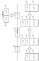
- the switch S1 compares the header H1 with the header H0 in the payload (references comparison). Thereby, the switch S1 recognizes that the original header H0 has been converted into the header H1 by the header conversion device T0.
- the switch S1 transmits a packet PKT3.
- a packet is encapsulated by a switch (or by a controller that receives a request from the switch).
- a switch or by a controller that receives a request from the switch.
- two types of headers before and after conversion are attached to the packet. By using this, it is possible to trace the flow.
- a network such as NAT or NAPT is converted by encapsulating a packet using the same header as the current packet header. Even when going through the appliance, the correspondence between the two flows before and after that can be grasped, and the flow can be traced end-to-end.
- the network appliance device that converts the packet header is modified. Therefore, it is possible to obtain packet header conversion information and track the flow.
- a network system including an encapsulation module having a function of notifying a controller of the header information in the header and the removed header information as header conversion information.
- the encapsulation module refers to the header information of the received packet of the second switch when the switch is the second switch in the subsequent stage of the header conversion device, and the controller uses the pair of the first header and the second header as header conversion information.
- the first header in the received packet is removed, the first header in the remaining part is replaced with the second header 2, and the packet is configured as “second header-payload”.
- a network system with the function of transferring via the second switch.
- a computer having a function as an encapsulation module, Means for checking if the received packet is an encapsulated packet; Means for copying the header information of the packet if the received packet is not an encapsulated packet; Means for attaching and encapsulating the duplicated header information to the received packet; If the received packet is an encapsulated packet, means for removing header information at the beginning of the encapsulated packet; Means for replacing header information in the remaining portion of the encapsulated packet with the removed header information; A computer comprising: means for generating header conversion information based on a combination of the header information in the remaining portion and the removed header information.
Landscapes
- Engineering & Computer Science (AREA)
- Computer Networks & Wireless Communication (AREA)
- Signal Processing (AREA)
- Computer Security & Cryptography (AREA)
- Data Exchanges In Wide-Area Networks (AREA)
Abstract
Description
オープンフローネットワークシステムでは、OFC(OpenFlow Controller)等のコントローラが、OFS(OpenFlow Switch)等のスイッチのフローテーブルを操作することによりスイッチの挙動を制御する。コントローラとスイッチは、セキュアチャネル(Secure Channel)で接続されている。
以下に、本発明の実施形態について添付図面を参照して説明する。
図1に示すように、本発明に係るネットワークシステムは、コントローラ10と、スイッチ20(20-i、i=1~n:nは台数)と、ヘッダ変換装置30を含む。
コントローラ10は、ネットワークの接続状態を示すトポロジ情報(topology)を基に、スイッチ20(20-i、i=1~n)を検知した際、パケット転送経路を計算し、当該経路に関連するスイッチのフローテーブルにエントリ(フローエントリ)の登録を行う。
スイッチ20(20-i、i=1~n)の各々は、受信したパケットを、自身のフローテーブルに登録されたエントリに従って転送する。
ヘッダ変換装置30は、所定のスイッチ20から受信したパケットのヘッダ情報の変換を行い、他のスイッチ20に転送する。
以下に、本発明に係るネットワークシステムを実現するための具体的なハードウェアの例について説明する。
コントローラ10は、事前に、スイッチ20-1のカプセル化モジュール21-1に対して、「所定のフローに関するパケットのカプセル化を行う」ように設定しておく。
次に、スイッチ20-1は、入力されたパケットをカプセル化モジュール21-1に渡す。ここでは、入力されたパケットの構成は、「IPヘッダ1-ペイロード」とする。
次に、ヘッダ変換装置30は、入力されたパケットのIPヘッダ1を参照し、アドレス変換処理を行い、IPヘッダ1をIPヘッダ2に変換する。
次に、スイッチ20-2は、入力されたパケットをカプセル化モジュール21-2に渡す。
なお、スイッチ20(20-i、i=1~n)における処理(送信側での「カプセル化」、及び受信側での「カプセル化の解除」)は、コントローラ10自身が行っても良い。この場合、コントローラ10は、カプセル化モジュール21(21-i、i=1~n)と連携する。また、コントローラ10と、カプセル化モジュール21(21-i、i=1~n)が、同一の装置であっても良い。スイッチ20(20-i、i=1~n)は、入力されたパケット全体をコントローラ10に送信し、応答として処理結果を受信する。例えば、図1において、コントローラ10は、カプセル化モジュール21-1及びカプセル化モジュール21-2と連携又は一体化しているものとする。スイッチ20-1は、「受信パケット」をコントローラ10に送信し、応答としてコントローラ10から「カプセル化されたパケット」を受信する。また、スイッチ20-2は、「カプセル化されたパケット」をコントローラ10に送信し、応答としてコントローラ10から「変換後ヘッダのみ付与されたパケット」を受信する。したがって、必要な場所で必要な処理を行うことができるならば、カプセル化モジュール21(21-i、i=1~n)の配置(所在)は、コントローラ10側及びスイッチ20(20-i、i=1~n)側のいずれでも良い。無論、スイッチ20(20-i、i=1~n)とコントローラ10の両方で処理を行うことも可能である。例えば、通常のパケットはスイッチ20(20-i、i=1~n)上で処理を行い、重要フローのパケットはコントローラ10上で処理を行うようにしても良い。
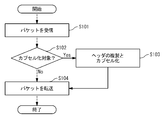
図2のフローチャートを用いて、カプセル化モジュール21-1の処理について説明する。
カプセル化モジュール21-1は、パケットを受信する。ここでは、受信パケットの構成は、「IPヘッダ1-ペイロード」とする。
次に、カプセル化モジュール21-1は、受信パケットがカプセル化対象のパケットであるかどうかを確認する。
カプセル化対象のパケットである場合、カプセル化モジュール21-1は、IPヘッダ1を参照し、IPヘッダ1を複製して、同じIPヘッダ1でカプセル化を行う。この場合、パケットの構成は、「IPヘッダ1-IPヘッダ1-ペイロード」となる。
カプセル化モジュール21-1は、スイッチ20-1を介してパケットを転送する。カプセル化対象のパケットである場合、パケットの構成は、「IPヘッダ1-IPヘッダ1-ペイロード」である。カプセル化対象のパケットでない場合、パケットの構成は、「IPヘッダ1-ペイロード」である。
ヘッダ変換装置30は、転送されたパケットのIPヘッダを変換する。カプセル化されたパケットである場合、ヘッダ変換装置30は、パケットの構成を、「IPヘッダ1-IPヘッダ1-ペイロード」から「IPヘッダ2-IPヘッダ1-ペイロード」に変換する。カプセル化されたパケットでない場合、ヘッダ変換装置30は、パケットの構成を、「IPヘッダ1-ペイロード」から「IPヘッダ2-ペイロード」に変換する。
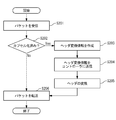
次に、図3のフローチャートを用いて、カプセル化モジュール21-2の処理について説明する。
カプセル化モジュール21-2は、パケットを受信する。
次に、カプセル化モジュール21-2は、受信パケットがカプセル化されたパケットであるかどうかを確認する。カプセル化されたパケットである場合、パケットの構成は、「IPヘッダ2-IPヘッダ1-ペイロード」である。カプセル化されたパケットでない場合、パケットの構成は、「IPヘッダ2-ペイロード」である。
カプセル化されたパケットである場合、カプセル化モジュール21-2は、IPヘッダ2とIPヘッダ1の二つを参照し、ヘッダ変換情報を作成する。ヘッダ変換情報は、変換前ヘッダ「IPヘッダ1」と、変換後ヘッダ「IPヘッダ2」のペア(組)となる。
次に、カプセル化モジュール21-2は、作成されたヘッダ変換情報をコントローラ10に送信する。
次に、カプセル化モジュール21-2は、カプセル化されたパケット「IPヘッダ2-IPヘッダ1-ペイロード」から「IPヘッダ2」を除去し、残りの「IPヘッダ1-ペイロード」の部分に対して、「IPヘッダ1」と「IPヘッダ2」を置き換える。このとき、カプセル化モジュール21-2は、最初に除去した「IPヘッダ2」を変換後ヘッダとして保持しておき、残りの「IPヘッダ1-ペイロード」の部分から変換前ヘッダ「IPヘッダ1」を除去し、変換後ヘッダ「IPヘッダ2」をペイロードに付け替える。すなわち、変換前ヘッダ「IPヘッダ1」を変換後ヘッダ「IPヘッダ2」に置換する。或いは、カプセル化されたパケット「IPヘッダ2-IPヘッダ1-ペイロード」から一旦全てのヘッダ「IPヘッダ2-IPヘッダ1」を除去した後、変換後ヘッダ「IPヘッダ2」のみペイロードに付与する。又は、受信パケットに付与された2段目のヘッダ(変換前ヘッダ「IPヘッダ1」)を除去する処理を行う。これにより、パケットの構成は、「IPヘッダ2-ペイロード」となる。
カプセル化モジュール21-2は、スイッチ20-2を介してパケットを転送する。パケットの構成は、「IPヘッダ2-ペイロード」である。
なお、コントローラ10は、ヘッダ変換情報を一度取得できれば良く、取得後はパケットのカプセル化を停止するように処理しても良い。
本発明では、オープンフローにおけるスイッチの一つである「OpenVSwitch」等が実装しているパケットのカプセル化機能を利用して、ヘッダ変換装置の前後でフローを識別する手法を開示する。
本発明では、オープンフローネットワークシステムのようなフローベースのネットワークにおいて、現在のパケットヘッダと同じヘッダを使ってパケットをカプセル化することにより、NATや、NAPT等のパケットヘッダを変換するようなネットワーク・アプライアンスを経由した場合にも、その前後での2つのフローの対応関係が把握でき、エンド・ツー・エンドでのフローの追跡が可能となる。
上記の実施形態の一部又は全部は、以下の付記のように記載することも可能である。但し、実際には、以下の記載例に限定されない。
パケット受信時に、フローを構成する各パケットを一律に制御するためのルールと動作が定義されたエントリが設定されたフローテーブルを検索して、エントリに定義されたルールに適合する受信パケットに対して、エントリに定義された動作を行う機能を持つスイッチと、
スイッチからパケットの問い合わせを受け、当該パケットを一律に制御するためのルールと動作が定義されたエントリを、スイッチのフローテーブルに設定する機能を持つコントローラと、
パケット受信時に、受信パケットの先頭のヘッダ情報の変換を行って転送する機能を持つヘッダ変換装置と、
スイッチが受信したパケットがカプセル化されたパケットかどうか確認し、カプセル化されたパケットでない場合、該パケットのヘッダ情報を複製し、複製したヘッダ情報を該受信パケットに付与してカプセル化してスイッチに渡し、カプセル化されたパケットである場合、該カプセル化されたパケットの先頭のヘッダ情報を除去し、残りの部分にあるヘッダ情報を該除去したヘッダ情報と置き換えてスイッチに渡し、該残りの部分にあるヘッダ情報と該除去したヘッダ情報との組をヘッダ変換情報としてコントローラに通知する機能を持つカプセル化モジュールと
を含む
ネットワークシステム。
付記1に記載のネットワークシステムであって、
カプセル化モジュールは、スイッチがヘッダ変換装置の前段にある第1スイッチである場合、第1スイッチの受信パケットのヘッダ情報である第1ヘッダを複製し、第1ヘッダを該受信パケットに付与して、ペイロードに第1ヘッダが二重に付与されている「第1ヘッダ-第1ヘッダ-ペイロード」という構成のパケットを、カプセル化されたパケットとして第1スイッチ経由で転送する機能を持ち、
ヘッダ変換装置は、第1スイッチからのパケットを受信した際、カプセル化されたパケットの先頭の第1ヘッダを第2ヘッダに変換して、「第2ヘッダ-第1ヘッダ-ペイロード」という構成のパケットにして転送する機能を持ち、
カプセル化モジュールは、スイッチがヘッダ変換装置の後段にある第2スイッチである場合、第2スイッチの受信パケットのヘッダ情報を参照し、第1ヘッダと第2ヘッダとの組をヘッダ変換情報としてコントローラに通知し、該受信パケットの先頭の第2ヘッダを除去し、残りの部分にある第1ヘッダを第2ヘッダ2と置き換えて、「第2ヘッダ-ペイロード」という構成のパケットにした上で、第2スイッチ経由で転送する機能を持つ
ネットワークシステム。
付記1に記載のネットワークシステムであって、
カプセル化モジュールは、スイッチ及びコントローラのうち少なくとも一方の側に設けられ、スイッチの側に設けられた場合、スイッチから直接パケットを受け取り、コントローラの側に設けられた場合、スイッチからコントローラ経由でパケットを受け取る機能を持つ
ネットワークシステム。
カプセル化モジュールとしての機能を持つ計算機であって、
受信パケットがカプセル化されたパケットかどうか確認する手段と、
受信パケットがカプセル化されたパケットでない場合、該パケットのヘッダ情報を複製する手段と、
複製したヘッダ情報を該受信パケットに付与してカプセル化する手段と、
受信パケットがカプセル化されたパケットである場合、該カプセル化されたパケットの先頭のヘッダ情報を除去する手段と、
該カプセル化されたパケットの残りの部分にあるヘッダ情報を該除去したヘッダ情報と置き換える手段と、
該残りの部分にあるヘッダ情報と該除去したヘッダ情報との組を基にヘッダ変換情報を生成する手段と
を具備する
計算機。
以上、本発明の実施形態を詳述してきたが、実際には、上記の実施形態に限られるものではなく、本発明の要旨を逸脱しない範囲の変更があっても本発明に含まれる。
Claims (8)
- 設定されたフローテーブルのエントリの内容に従って受信パケットを処理する機能を持つスイッチと、
前記スイッチからパケットの問い合わせを受け、該パケットを一律に制御するためのルールと動作が定義されたエントリを、前記スイッチのフローテーブルに設定する機能を持つコントローラと、
前記スイッチ及び前記コントローラのうち少なくとも一方からパケットを受け取り、該パケットのヘッダと同じヘッダを使ってパケットをカプセル化する機能を持つカプセル化モジュールと
を含む
ネットワークシステム。 - 請求項1に記載のネットワークシステムであって、
前記スイッチからパケットを受信した時に、受信パケットの先頭のヘッダ情報の変換を行って、他のスイッチに転送する機能を持つヘッダ変換装置
を更に含み、
前記カプセル化モジュールは、前記カプセル化されたパケットが前記ヘッダ変換装置を経過した場合、変換前と変換後の2種類のヘッダが付与されたパケットを受け取り、変換前と変換後の2種類のヘッダの組を前記コントローラに通知する機能を持つ
ネットワークシステム。 - 請求項1又は2に記載のネットワークシステムであって、
前記カプセル化モジュールは、
前記スイッチが受信したパケットがカプセル化されたパケットかどうか確認する機能を持ち、
カプセル化されたパケットでない場合、該パケットのヘッダ情報を複製し、複製したヘッダ情報を該受信パケットに付与してカプセル化して前記スイッチに渡す機能を持ち、
カプセル化されたパケットである場合、該カプセル化されたパケットの先頭のヘッダ情報と本来のパケットのヘッダ情報との組をヘッダ変換情報として前記コントローラに通知する機能を持ち、
該カプセル化されたパケットを、前記先頭のヘッダ情報のみ付与されたパケットに変換して前記スイッチに渡す機能を持つ
ネットワークシステム。 - カプセル化モジュールとしての機能を持つ計算機であって、
設定されたフローテーブルのエントリの内容に従って受信パケットを処理する機能を持つスイッチと、前記スイッチからパケットの問い合わせを受け、該パケットを一律に制御するためのルールと動作が定義されたエントリを、前記スイッチのフローテーブルに設定する機能を持つコントローラと、のうち少なくとも一方からパケットを受け取る手段と、
該パケットに対し、該パケットのヘッダと同じヘッダを使ってパケットをカプセル化する手段と
を具備する
計算機。 - 請求項4に記載の計算機であって、
前記カプセル化されたパケットが、受信パケットの先頭のヘッダ情報の変換を行って転送する機能を持つヘッダ変換装置を経過した場合、変換前と変換後の2種類のヘッダが付与されたパケットを受け取り、変換前と変換後の2種類のヘッダを参照する手段
を更に具備する
計算機。 - 請求項4又は5に記載の計算機であって、
受信パケットがカプセル化されたパケットかどうか確認する手段と、
前記受信パケットがカプセル化されたパケットでない場合、該パケットのヘッダ情報を複製する手段と、
複製したヘッダ情報を該受信パケットに付与してカプセル化する手段と、
前記受信パケットがカプセル化されたパケットである場合、該カプセル化されたパケットの先頭のヘッダ情報と本来のパケットのヘッダ情報との組を基にヘッダ変換情報を生成する手段と、
該カプセル化されたパケットを、前記先頭のヘッダ情報のみ付与されたパケットに変換する手段と
を具備する
計算機。 - スイッチにおいて、設定されたフローテーブルのエントリの内容に従って受信パケットを処理することと、
コントローラにおいて、前記スイッチからパケットの問い合わせを受け、該パケットを一律に制御するためのルールと動作が定義されたエントリを、前記スイッチのフローテーブルに設定することと、
カプセル化モジュールにおいて、前記スイッチ及び前記コントローラのうち少なくとも一方からパケットを受け取り、該パケットのヘッダと同じヘッダを使ってパケットをカプセル化することと
を含む
ネットワークフロー追跡方法。 - カプセル化モジュールとしての機能を持つ計算機により実行されるプログラムを格納した記憶媒体であって、
設定されたフローテーブルのエントリの内容に従って受信パケットを処理する機能を持つスイッチと、前記スイッチからパケットの問い合わせを受けて該パケットを一律に制御するためのルールと動作が定義されたエントリを前記スイッチのフローテーブルに設定する機能を持つコントローラと、のうち少なくとも一方からパケットを受け取るステップと、
該パケットに対し、該パケットのヘッダと同じヘッダを使ってパケットをカプセル化するステップと
を計算機に実行させるためのプログラムを格納した
記憶媒体。
Priority Applications (5)
| Application Number | Priority Date | Filing Date | Title |
|---|---|---|---|
| EP11858533.0A EP2677705A4 (en) | 2011-02-17 | 2011-12-08 | NETWORK SYSTEM AND NETWORK FLOW TRACKING PROCEDURE |
| CN201180067713.4A CN103380600B (zh) | 2011-02-17 | 2011-12-08 | 网络系统和网络流跟踪方法 |
| JP2012557790A JP5565476B2 (ja) | 2011-02-17 | 2011-12-08 | ネットワークシステム、及びネットワークフロー追跡方法 |
| US13/983,001 US9313128B2 (en) | 2011-02-17 | 2011-12-08 | Network system and network flow tracing method |
| US15/072,558 US9560177B2 (en) | 2011-02-17 | 2016-03-17 | Network system and network flow tracing method |
Applications Claiming Priority (2)
| Application Number | Priority Date | Filing Date | Title |
|---|---|---|---|
| JP2011-031752 | 2011-02-17 | ||
| JP2011031752 | 2011-02-17 |
Related Child Applications (2)
| Application Number | Title | Priority Date | Filing Date |
|---|---|---|---|
| US13/983,001 A-371-Of-International US9313128B2 (en) | 2011-02-17 | 2011-12-08 | Network system and network flow tracing method |
| US15/072,558 Continuation US9560177B2 (en) | 2011-02-17 | 2016-03-17 | Network system and network flow tracing method |
Publications (1)
| Publication Number | Publication Date |
|---|---|
| WO2012111222A1 true WO2012111222A1 (ja) | 2012-08-23 |
Family
ID=46672172
Family Applications (1)
| Application Number | Title | Priority Date | Filing Date |
|---|---|---|---|
| PCT/JP2011/078439 Ceased WO2012111222A1 (ja) | 2011-02-17 | 2011-12-08 | ネットワークシステム、及びネットワークフロー追跡方法 |
Country Status (5)
| Country | Link |
|---|---|
| US (2) | US9313128B2 (ja) |
| EP (1) | EP2677705A4 (ja) |
| JP (2) | JP5565476B2 (ja) |
| CN (1) | CN103380600B (ja) |
| WO (1) | WO2012111222A1 (ja) |
Cited By (6)
| Publication number | Priority date | Publication date | Assignee | Title |
|---|---|---|---|---|
| JP2015032932A (ja) * | 2013-08-01 | 2015-02-16 | 日本電信電話株式会社 | キャリア網における経路制御システム及び方法 |
| CN105027515A (zh) * | 2013-06-27 | 2015-11-04 | Sk电信有限公司 | 用于在内容传输系统中处理数据的设备和方法 |
| JP2015231059A (ja) * | 2014-06-03 | 2015-12-21 | 富士通株式会社 | 経路設定装置及び経路設定方法 |
| CN105530186A (zh) * | 2014-10-15 | 2016-04-27 | 日本电气株式会社 | 控制装置、控制方法和介质 |
| JPWO2015125801A1 (ja) * | 2014-02-19 | 2017-03-30 | 日本電気株式会社 | ネットワーク制御方法、ネットワークシステムと装置及びプログラム |
| WO2024176344A1 (ja) * | 2023-02-21 | 2024-08-29 | 日本電信電話株式会社 | カプセル化装置、通信システム、カプセル化方法、および、カプセル化プログラム |
Families Citing this family (14)
| Publication number | Priority date | Publication date | Assignee | Title |
|---|---|---|---|---|
| JP5818268B2 (ja) * | 2010-11-02 | 2015-11-18 | 日本電気株式会社 | 通信システム、制御装置、経路制御方法およびプログラム |
| US9729425B2 (en) * | 2012-11-29 | 2017-08-08 | Futurewei Technologies, Inc. | Transformation and unified control of hybrid networks composed of OpenFlow switches and other programmable switches |
| US9755969B2 (en) | 2014-03-04 | 2017-09-05 | International Business Machines Corporation | Route tracing in software defined networks |
| WO2016000184A1 (zh) | 2014-06-30 | 2016-01-07 | 华为技术有限公司 | 一种交换机模式切换方法、设备及系统 |
| US9729348B2 (en) * | 2015-06-04 | 2017-08-08 | Cisco Technology, Inc. | Tunnel-in-tunnel source address correction |
| CN105763465B (zh) * | 2016-01-29 | 2019-01-22 | 新华三技术有限公司 | 一种分布式组合流量控制方法及装置 |
| US10866917B2 (en) * | 2018-12-03 | 2020-12-15 | Ati Technologies Ulc | Inter device data exchange via external bus by utilizing communication port |
| US11366610B2 (en) | 2018-12-20 | 2022-06-21 | Marvell Asia Pte Ltd | Solid-state drive with initiator mode |
| WO2020183444A1 (en) | 2019-03-14 | 2020-09-17 | Marvell Asia Pte, Ltd. | Transferring data between solid state drives (ssds) via a connection between the ssds |
| WO2020183246A2 (en) | 2019-03-14 | 2020-09-17 | Marvell Asia Pte, Ltd. | Termination of non-volatile memory networking messages at the drive level |
| CN118502672A (zh) * | 2019-03-14 | 2024-08-16 | 马维尔亚洲私人有限公司 | 启用以太网的固态驱动器(ssd) |
| CN112491576B (zh) * | 2020-09-29 | 2024-09-20 | 中兴通讯股份有限公司 | 网络配置的发送方法及装置、存储介质、电子装置 |
| US12047269B2 (en) * | 2022-03-29 | 2024-07-23 | Cisco Technology, Inc. | End-to-end flow visibility in a data network including service appliances |
| WO2025252321A1 (en) * | 2024-06-07 | 2025-12-11 | Huawei Cloud Computing Technologies Co., Ltd. | Network telemetry apparatus and methods |
Citations (3)
| Publication number | Priority date | Publication date | Assignee | Title |
|---|---|---|---|---|
| JP2005210518A (ja) | 2004-01-23 | 2005-08-04 | Matsushita Electric Works Ltd | 発信源追跡情報提供装置及び発信源追跡装置 |
| JP2010199669A (ja) * | 2009-02-23 | 2010-09-09 | Nippon Telegr & Teleph Corp <Ntt> | バックボーン網におけるトラヒック情報収集方法、トラヒック情報収集装置、及びプログラム |
| JP2011031752A (ja) | 2009-07-31 | 2011-02-17 | Honda Motor Co Ltd | 自動二輪車の蒸発燃料処理装置 |
Family Cites Families (19)
| Publication number | Priority date | Publication date | Assignee | Title |
|---|---|---|---|---|
| US6907036B1 (en) * | 1999-06-28 | 2005-06-14 | Broadcom Corporation | Network switch enhancements directed to processing of internal operations in the network switch |
| WO2004066563A1 (ja) | 2003-01-21 | 2004-08-05 | Fujitsu Limited | バーチャルネットワークシステムのキャリアネットワークおよび該キャリアネットワークの通信ノード |
| JP2004364141A (ja) * | 2003-06-06 | 2004-12-24 | Hitachi Communication Technologies Ltd | Ipアドレス変換装置およびパケット転送装置 |
| US7457626B2 (en) * | 2004-03-19 | 2008-11-25 | Microsoft Corporation | Virtual private network structure reuse for mobile computing devices |
| JP4476847B2 (ja) | 2005-03-04 | 2010-06-09 | ソフトバンクテレコム株式会社 | パケット通信システムの通信制御方法およびパケット通信システム |
| US7656795B2 (en) * | 2005-04-11 | 2010-02-02 | International Business Machines Corporation | Preventing duplicate sources from clients served by a network address port translator |
| CN100459574C (zh) | 2005-09-19 | 2009-02-04 | 北京大学 | 对网络流进行分类、状态跟踪和报文处理的装置和方法 |
| JP4331154B2 (ja) * | 2005-09-29 | 2009-09-16 | パナソニック株式会社 | 情報処理システム、トンネル通信装置、及びトンネル通信方法 |
| US7817549B1 (en) | 2006-06-30 | 2010-10-19 | Extreme Networks, Inc. | Flexible flow-aging mechanism |
| KR100757881B1 (ko) | 2006-09-20 | 2007-09-11 | 삼성전자주식회사 | Nat를 이용한 자동 터널링 방법 및 그 시스템 |
| JP4629639B2 (ja) * | 2006-09-29 | 2011-02-09 | 富士通株式会社 | パケット中継装置 |
| EP1947819A1 (en) * | 2007-01-18 | 2008-07-23 | Matsushita Electric Industrial Co., Ltd. | Header reduction of data packets by route optimization procedure |
| EP2007078A1 (en) | 2007-06-19 | 2008-12-24 | Panasonic Corporation | Header size reduction of data packets |
| JP2009194713A (ja) | 2008-02-15 | 2009-08-27 | Oki Electric Ind Co Ltd | パケット中継システム |
| US8180892B2 (en) * | 2008-12-22 | 2012-05-15 | Kindsight Inc. | Apparatus and method for multi-user NAT session identification and tracking |
| JP5561173B2 (ja) * | 2009-02-03 | 2014-07-30 | 日本電気株式会社 | アプリケーションスイッチシステム、及びアプリケーションスイッチ方法 |
| WO2010103909A1 (ja) * | 2009-03-09 | 2010-09-16 | 日本電気株式会社 | OpenFlow通信システムおよびOpenFlow通信方法 |
| WO2012006190A1 (en) * | 2010-06-29 | 2012-01-12 | Huawei Technologies Co., Ltd. | Delegate gateways and proxy for target hosts in large layer 2 and address resolution with duplicated internet protocol addresses |
| US8863256B1 (en) * | 2011-01-14 | 2014-10-14 | Cisco Technology, Inc. | System and method for enabling secure transactions using flexible identity management in a vehicular environment |
-
2011
- 2011-12-08 CN CN201180067713.4A patent/CN103380600B/zh active Active
- 2011-12-08 WO PCT/JP2011/078439 patent/WO2012111222A1/ja not_active Ceased
- 2011-12-08 US US13/983,001 patent/US9313128B2/en active Active
- 2011-12-08 JP JP2012557790A patent/JP5565476B2/ja active Active
- 2011-12-08 EP EP11858533.0A patent/EP2677705A4/en not_active Withdrawn
-
2014
- 2014-06-10 JP JP2014119364A patent/JP5862706B2/ja not_active Expired - Fee Related
-
2016
- 2016-03-17 US US15/072,558 patent/US9560177B2/en active Active
Patent Citations (3)
| Publication number | Priority date | Publication date | Assignee | Title |
|---|---|---|---|---|
| JP2005210518A (ja) | 2004-01-23 | 2005-08-04 | Matsushita Electric Works Ltd | 発信源追跡情報提供装置及び発信源追跡装置 |
| JP2010199669A (ja) * | 2009-02-23 | 2010-09-09 | Nippon Telegr & Teleph Corp <Ntt> | バックボーン網におけるトラヒック情報収集方法、トラヒック情報収集装置、及びプログラム |
| JP2011031752A (ja) | 2009-07-31 | 2011-02-17 | Honda Motor Co Ltd | 自動二輪車の蒸発燃料処理装置 |
Non-Patent Citations (3)
| Title |
|---|
| OPENFLOW SWITCH SPECIFICATION, VERSION 1.0.0, 31 December 2009 (2009-12-31), Retrieved from the Internet <URL:http: //www.openflowswitch.org/documents/openflow-spec- vl.0.0.pdf> |
| See also references of EP2677705A4 |
| TERUAKI YOKOYAMA ET AL.: "NAT Gateway o Tsuka suru Flow no Monai deno Shikibetsu Shuho no Teian", IPSJ SIG NOTES, vol. 2001, no. 59, 8 June 2001 (2001-06-08), pages 95 - 100, XP008171040 * |
Cited By (9)
| Publication number | Priority date | Publication date | Assignee | Title |
|---|---|---|---|---|
| CN105027515A (zh) * | 2013-06-27 | 2015-11-04 | Sk电信有限公司 | 用于在内容传输系统中处理数据的设备和方法 |
| CN105027515B (zh) * | 2013-06-27 | 2018-01-30 | Sk电信有限公司 | 用于在内容传输系统中处理数据的设备和方法 |
| US9893991B2 (en) | 2013-06-27 | 2018-02-13 | Sk Telecom Co., Ltd. | Device and method for processing data in content transmission system |
| JP2015032932A (ja) * | 2013-08-01 | 2015-02-16 | 日本電信電話株式会社 | キャリア網における経路制御システム及び方法 |
| JPWO2015125801A1 (ja) * | 2014-02-19 | 2017-03-30 | 日本電気株式会社 | ネットワーク制御方法、ネットワークシステムと装置及びプログラム |
| US10097458B2 (en) | 2014-02-19 | 2018-10-09 | Nec Corporation | Network control method, network system, apparatus, and program |
| JP2015231059A (ja) * | 2014-06-03 | 2015-12-21 | 富士通株式会社 | 経路設定装置及び経路設定方法 |
| CN105530186A (zh) * | 2014-10-15 | 2016-04-27 | 日本电气株式会社 | 控制装置、控制方法和介质 |
| WO2024176344A1 (ja) * | 2023-02-21 | 2024-08-29 | 日本電信電話株式会社 | カプセル化装置、通信システム、カプセル化方法、および、カプセル化プログラム |
Also Published As
| Publication number | Publication date |
|---|---|
| US20160198025A1 (en) | 2016-07-07 |
| JP2014195326A (ja) | 2014-10-09 |
| US20130315248A1 (en) | 2013-11-28 |
| CN103380600B (zh) | 2016-11-09 |
| EP2677705A1 (en) | 2013-12-25 |
| JP5565476B2 (ja) | 2014-08-06 |
| JP5862706B2 (ja) | 2016-02-16 |
| EP2677705A4 (en) | 2016-06-01 |
| JPWO2012111222A1 (ja) | 2014-07-03 |
| US9560177B2 (en) | 2017-01-31 |
| CN103380600A (zh) | 2013-10-30 |
| US9313128B2 (en) | 2016-04-12 |
Similar Documents
| Publication | Publication Date | Title |
|---|---|---|
| JP5565476B2 (ja) | ネットワークシステム、及びネットワークフロー追跡方法 | |
| JP5610247B2 (ja) | ネットワークシステム、及びポリシー経路設定方法 | |
| JP5811253B2 (ja) | ネットワークシステム、及びネットワーク管理方法 | |
| US8971342B2 (en) | Switch and flow table controlling method | |
| JP5660211B2 (ja) | 通信経路制御システム、及び通信経路制御方法 | |
| EP2615782A1 (en) | Computer system and communication method in computer system | |
| US11863454B2 (en) | Systems and methods for scalable validation of multiple paths in a network using segment routing | |
| JP2015511074A (ja) | 通信のためのシステム及び方法 | |
| CN103329488A (zh) | 网络系统和路由控制方法 | |
| JP5861772B2 (ja) | ネットワークアプライアンス冗長化システム、制御装置、ネットワークアプライアンス冗長化方法及びプログラム | |
| JP5858141B2 (ja) | 制御装置、通信装置、通信システム、通信方法及びプログラム | |
| WO2012121098A1 (ja) | ネットワークシステム、パケット処理方法、及び記憶媒体 | |
| CN103973554A (zh) | 路由方法、系统及相关设备 | |
| JP2013115733A (ja) | ネットワークシステム、及びネットワーク制御方法 | |
| JP2015511097A (ja) | 通信システム、制御装置、通信方法、及びプログラム | |
| HK1180495A (en) | Network system and network managing method | |
| CN105577578A (zh) | 网络装置及其处理封包的方法 | |
| JP2014212398A (ja) | 通信システム、通信ノード、パケット処理方法及びプログラム |
Legal Events
| Date | Code | Title | Description |
|---|---|---|---|
| 121 | Ep: the epo has been informed by wipo that ep was designated in this application |
Ref document number: 11858533 Country of ref document: EP Kind code of ref document: A1 |
|
| REEP | Request for entry into the european phase |
Ref document number: 2011858533 Country of ref document: EP |
|
| WWE | Wipo information: entry into national phase |
Ref document number: 2011858533 Country of ref document: EP |
|
| WWE | Wipo information: entry into national phase |
Ref document number: 13983001 Country of ref document: US |
|
| ENP | Entry into the national phase |
Ref document number: 2012557790 Country of ref document: JP Kind code of ref document: A |
|
| NENP | Non-entry into the national phase |
Ref country code: DE |