WO2012111303A1 - スパークプラグ - Google Patents
スパークプラグ Download PDFInfo
- Publication number
- WO2012111303A1 WO2012111303A1 PCT/JP2012/000937 JP2012000937W WO2012111303A1 WO 2012111303 A1 WO2012111303 A1 WO 2012111303A1 JP 2012000937 W JP2012000937 W JP 2012000937W WO 2012111303 A1 WO2012111303 A1 WO 2012111303A1
- Authority
- WO
- WIPO (PCT)
- Prior art keywords
- intermediate member
- electrode
- spark plug
- ground electrode
- content
- Prior art date
- Legal status (The legal status is an assumption and is not a legal conclusion. Google has not performed a legal analysis and makes no representation as to the accuracy of the status listed.)
- Ceased
Links
Images


Classifications
-
- H—ELECTRICITY
- H01—ELECTRIC ELEMENTS
- H01T—SPARK GAPS; OVERVOLTAGE ARRESTERS USING SPARK GAPS; SPARKING PLUGS; CORONA DEVICES; GENERATING IONS TO BE INTRODUCED INTO NON-ENCLOSED GASES
- H01T13/00—Sparking plugs
- H01T13/02—Details
- H01T13/06—Covers forming a part of the plug and protecting it against adverse environment
-
- C—CHEMISTRY; METALLURGY
- C22—METALLURGY; FERROUS OR NON-FERROUS ALLOYS; TREATMENT OF ALLOYS OR NON-FERROUS METALS
- C22C—ALLOYS
- C22C19/00—Alloys based on nickel or cobalt
- C22C19/03—Alloys based on nickel or cobalt based on nickel
- C22C19/05—Alloys based on nickel or cobalt based on nickel with chromium
-
- H—ELECTRICITY
- H01—ELECTRIC ELEMENTS
- H01T—SPARK GAPS; OVERVOLTAGE ARRESTERS USING SPARK GAPS; SPARKING PLUGS; CORONA DEVICES; GENERATING IONS TO BE INTRODUCED INTO NON-ENCLOSED GASES
- H01T13/00—Sparking plugs
- H01T13/20—Sparking plugs characterised by features of the electrodes or insulation
-
- H—ELECTRICITY
- H01—ELECTRIC ELEMENTS
- H01T—SPARK GAPS; OVERVOLTAGE ARRESTERS USING SPARK GAPS; SPARKING PLUGS; CORONA DEVICES; GENERATING IONS TO BE INTRODUCED INTO NON-ENCLOSED GASES
- H01T13/00—Sparking plugs
- H01T13/20—Sparking plugs characterised by features of the electrodes or insulation
- H01T13/39—Selection of materials for electrodes
Definitions
- the present invention relates to a spark plug.
- a configuration in which a noble metal tip is disposed at the tip of a ground electrode via an intermediate member (see, for example, Patent Document 1).
- the noble metal tip is disposed on the ground electrode, the flame extinguishing action that the ground electrode takes away the energy of flame nuclei generated by the discharge can be suppressed by keeping the ground electrode away from the discharge gap. Therefore, when the noble metal tip is connected to the ground electrode, by arranging the intermediate member, it is possible to sufficiently secure the distance between the ground electrode and the discharge gap while suppressing the amount of noble metal used. .
- the intermediate member described above is composed of a nickel alloy or the like that is generally said to have extremely high corrosion resistance, corrosion may have progressed to an unacceptable extent during long-term use.
- a member arranged in the vicinity of the discharge gap in the spark plug such as an intermediate member, corrosion due to the thermal cycle is likely to proceed. Therefore, further improvement in durability in a structure in which the noble metal tip is attached to the ground electrode via the intermediate member has been desired.
- the structure in which the noble metal tip is attached via the intermediate member can be employed not only in the ground electrode but also in the center electrode. Therefore, such a problem can occur not only in the ground electrode but also in the center electrode side. It was.
- the present invention has been made to solve the above-described conventional problems, and an object thereof is to improve durability in a structure in which a noble metal tip is attached to a ground electrode or a center electrode via an intermediate member.
- the present invention has been made to solve at least a part of the problems described above, and can be implemented as the following forms or application examples.
- a spark plug comprising: a ground electrode, one end of which is joined to the metal shell, and the other end is disposed so as to face the center electrode;
- At least one of the center electrode and the ground electrode has an intermediate member that connects the center electrode or the ground electrode and the noble metal tip,
- the intermediate member includes a chip joint part to which the noble metal chip is joined, and an electrode joint part adjacent to the chip joint part and having a larger diameter than the chip joint part and joined to the center electrode or the ground electrode.
- the intermediate member contains nickel (Ni) as a main component and chromium (Cr) in an amount of 15 to 25 wt%, and the surface portion of the intermediate member has a silicon (Si) content of 0.
- a spark plug having a content of aluminum (Al) per unit volume of 0.03 mg / mm 3 to 0.10 mg / mm 3 , and a content of 04 mg / mm 3 to 0.12 mg / mm 3 .
- [Application Example 5] 4 The spark plug according to any one of application examples 1 to 3, wherein a content ratio of iron (Fe) in the intermediate member is 500 ppm or less. According to the spark plug described in Application Example 5, since the intermediate member does not substantially contain iron (Fe), even when the spark plug is exposed to a cooling cycle involving repeated heating and cooling, the spark plug is used. The durability and corrosion resistance of the plug can be maintained.
- the present invention can be realized in various forms other than those described above, for example, in the form of a spark plug manufacturing method and the like.
- FIG. 1 is a partial cross-sectional view of a spark plug 100.
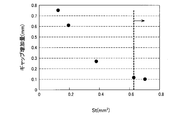
- FIG. FIG. 4 is an explanatory diagram showing an enlarged tip of a ground electrode 30. It is explanatory drawing which shows the specific conditions in the intermediate member of each sample, and an evaluation result. It is explanatory drawing which shows the result of having investigated the influence of Se / St. It is explanatory drawing which shows an example of the mode of the intermediate member after execution of a cooling-heat cycle. It is explanatory drawing which shows the result of having investigated the influence by the presence or absence of iron (Fe) containing. It is explanatory drawing which shows the result of having investigated the influence on the durability of the area St. It is a graph which shows the relationship between area St and gap increase amount.
- FIG. 1 is a partial cross-sectional view of a spark plug 100 as an embodiment of the present invention.
- the spark plug 100 includes an insulator 10, a center electrode 20, a ground electrode 30, a terminal fitting 40, and a metal shell 50.
- the rod-shaped center electrode 20 protruding from one end of the insulator 10 is electrically connected to a terminal fitting 40 provided at the other end of the insulator 10 through the inside of the insulator 10.
- the outer periphery of the center electrode 20 is held by the insulator 10, and the outer periphery of the insulator 10 is held by the metallic shell 50 at a position away from the terminal fitting 40.
- the ground electrode 30 electrically connected to the metal shell 50 forms a spark gap, which is a gap for generating a spark, between the tip of the center electrode 20.
- the spark plug 100 is attached to a mounting screw hole 201 provided in the engine head 200 of the internal combustion engine via a metal shell 50.
- a spark is generated in a spark gap formed between the center electrode 20 and the ground electrode 30.
- the insulator 10 is an insulator formed by firing a ceramic material such as alumina.
- the insulator 10 is a cylindrical member having a shaft hole 12 that accommodates the center electrode 20 and the terminal fitting 40 formed at the center.
- a central body 19 having a large outer diameter is formed at the axial center of the insulator 10.
- a rear end side body portion 18 that insulates between the terminal metal fitting 40 and the metal shell 50 is formed on the terminal metal fitting 40 side of the central body portion 19.
- a front end side body portion 17 having an outer diameter smaller than that of the rear end side body portion 18 is formed on the center electrode 20 side with respect to the central body portion 19, and a front end side body portion 17 is provided further ahead of the front end side body portion 17.
- a leg length portion 13 having a smaller outer diameter and a smaller outer diameter toward the center electrode 20 side is formed.
- the main metal fitting 50 is a cylindrical metal fitting that surrounds and holds a portion extending from a part of the rear end side body portion 18 of the insulator 10 to the leg length portion 13, and is made of low carbon steel in this embodiment.
- the metal shell 50 includes a tool engaging portion 51, a mounting screw portion 52, and a seal portion 54.
- a tool (not shown) for attaching the spark plug 100 to the engine head 200 is fitted into the tool engaging portion 51 of the metal shell 50.
- the mounting screw portion 52 of the metal shell 50 has a thread that is screwed into the mounting screw hole 201 of the engine head 200.
- the seal portion 54 of the metal shell 50 is formed in a hook shape at the base of the mounting screw portion 52, and an annular gasket 5 formed by bending a plate is inserted between the seal portion 54 and the engine head 200.
- the front end surface 57 of the metal shell 50 has a hollow circular shape, and the center electrode 20 projects from the long leg portion 13 of the insulator 10 at the center thereof.
- the center electrode 20 is a rod-shaped member in which a core material 25 having better thermal conductivity than the electrode base material 21 is embedded in an electrode base material 21 formed in a bottomed cylindrical shape.
- the electrode base material 21 is made of a nickel alloy containing nickel as a main component
- the core member 25 is made of copper or an alloy containing copper as a main component.
- FIG. 2 is an explanatory view showing the tip of the ground electrode 30 in an enlarged manner.
- the ground electrode 30 is bent in a direction intersecting the direction of the axis O, which is the direction in which the center electrode 20 extends, with the base portion 32 joined to the distal end surface 57 of the metal shell 50.
- the inner surface faces the center electrode tip 90 welded to the center electrode 20 on the axis O.
- the ground electrode 30 is made of a metal having high corrosion resistance.
- a nickel alloy such as Inconel (registered trademark) 600 or 601 is used.
- An intermediate member 60 having corrosion resistance is connected to one side surface of the tip portion 31 of the ground electrode 30, which faces the tip portion 22 of the center electrode 20 on the axis O.
- the intermediate member 60 is provided adjacent to (stacked on) the chip joint 61 to which the ground electrode tip 70 is welded, and is a surface perpendicular to the axis O as compared to the chip joint 61 (hereinafter referred to as “chip joint 61”).
- chip joint 61 an electrode joint 62 welded to the ground electrode 30.
- each of the chip joint portion 61 and the electrode joint portion 62 has a substantially cylindrical shape in which the diameter of the cross section (hereinafter, the diameter in the cross section is also simply referred to as a diameter) is substantially uniform as a whole.
- the joint portion 62 has a larger diameter, and the electrode joint portion 62 is formed in a bowl shape that is larger in the radial direction than the chip joint portion 61.
- the shape of the intermediate member 60 described above can be formed by various methods such as cutting, but in the present embodiment, the intermediate member 60 is formed by plastic processing (header processing).
- the tip joint portion 61 and the electrode joint portion 62 need to have a cylindrical shape in a strict sense that the end surfaces are circular flat surfaces. There is no. For example, it is good also as providing a convex part in the surface of the electrode junction part 62 in the connection part welded to the ground electrode 30.
- FIG. 1 each of the chip connecting portion 61 and the electrode joint portion 62, the ground electrode tip 70, or the center electrode tip 90 constituting the intermediate member may have a shape other than a cylindrical shape, for example, a quadrangular prism shape.
- the chip joint portion 61 preferably has a diameter longer than the diameter of the cross section of the ground electrode chip 70. Moreover, in order to ensure the uniformity of flame propagation, it is desirable that the chip joint 61 disposed in the vicinity of the spark gap is small. That is, it is desirable that the diameter of the chip joint portion 61 is smaller. Therefore, in this embodiment, the diameter of the chip joint portion 61 is formed to be approximately equal to the diameter of the ground electrode chip 70.
- the reason why the diameter of the electrode joint portion 62 is made larger than the diameter of the tip joint portion 61 is for convenience in the operation of welding the intermediate member 60 to the ground electrode 30, and between the intermediate member 60 and the ground electrode 30. This is because the bonding force is improved and the reliability of the bonding is improved. Furthermore, in the present embodiment, the ratio of the cross-sectional area Se (see FIG. 2) of the electrode joint 62 to the cross-sectional area St (see FIG. 2) of the chip joint 61 is 2.5 or more (2.5 ⁇ By using Se / St), the corrosion resistance of the intermediate member 60 is improved.
- the area Se of the cross section of the electrode bonding portion 62 can also be referred to as “the area when the electrode bonding portion 62 is projected onto a virtual plane (see FIG.
- the area of the cross section may be slightly increased in the vicinity of the boundary between the tip joint 61 and the electrode joint 62. . Therefore, in this embodiment, the area St of the cross section of the chip connection portion 61 is the area of the cross section in a region where the diameter is uniform. The effect of improving the corrosion resistance of the intermediate member 60 by setting the ratio of the area Se of the cross section of the electrode joint 62 to the area St of the cross section of the chip joint 61 will be described in detail later.
- the upper limit value of the ratio of the cross-sectional area Se of the electrode joint portion 62 to the cross-sectional area St of the chip joint portion 61 is 3.5 (Se / St ⁇ 3. 5) is desirable.
- 2.5 ⁇ Se / St and the area St of the cross section of the chip joint 61 is 0.64 mm 2 or more, thereby improving the durability of the ground electrode chip 70. ing.
- the effect of improving the durability of the ground electrode tip 70 by setting the area St of the cross section of the chip joining portion 61 to the above-mentioned value will be described in detail later.
- the intermediate member 60 is formed of, for example, a nickel alloy containing nickel (Ni) as a main component and containing at least chromium (Cr), silicon (Si), and aluminum (Al). More specifically, the content ratio of chromium (Cr) is 15 to 25 wt%.
- the content per unit volume of silicon (Si) (weight) is 0.04mg / mm 3 ⁇ 0.12mg / mm 3.
- the content (weight) per unit volume of aluminum (Al) is 0.03 mg / mm 3 to 0.10 mg / mm 3 .
- the entire intermediate member 60 has a uniform composition. In particular, it is desirable that the content per unit volume of silicon (Si) is larger than the content per unit volume of aluminum (Al).
- the corrosion resistance of the intermediate member 60 can be improved.
- the relationship between the composition of the intermediate member 60 and the corrosion resistance will be described in detail later.
- the content per unit volume of each component contained in the intermediate member can be determined as follows, for example. That is, after the intermediate member to be measured is cut out to a predetermined size (for example, 2 mm square), the density of the intermediate member is first obtained by measuring the weight of the cut sample. Then, quantitative analysis is performed on the cut sample using an EPMA (electron beam microanalyzer), and the concentration (% by weight) of each component (element) constituting the intermediate member to be measured is obtained. By multiplying the density described above by the concentration of each component, the content per unit volume of each component can be derived.
- EPMA electron beam microanalyzer
- the intermediate member 60 made of an alloy does not substantially contain iron (Fe).
- the intermediate member may be used when iron (Fe) is contained as an impurity in the constituent material of the intermediate member 60.
- iron (Fe) is inevitably mixed.
- the content weight ratio of iron (Fe) in the intermediate member 60 is preferably 500 ppm or less.
- the welding method between the intermediate member 60 and the ground electrode tip 70 can be, for example, fusion welding. Specifically, in this embodiment, laser welding is performed. When the ground electrode tip 70 and the intermediate member 60 are melted, a melted portion 80 is formed at the boundary between them.
- the welding between the intermediate member 60 and the ground electrode 30 can be, for example, pressure welding. Specifically, in the embodiment, resistance welding is performed.
- the ground electrode tip 70 is a member provided to improve the spark wear resistance of the ground electrode 30 and is a noble metal tip formed mainly of a high melting point noble metal.
- the ground electrode tip 70 is made of, for example, platinum (Pt), iridium (Ir), ruthenium (Ru), rhodium (Rh), or an alloy thereof. In this embodiment, the ground electrode tip 70 is made of a Pt—Rh alloy. .
- the ground electrode tip 70 is formed in a substantially cylindrical shape, and as described above, the cross-sectional diameter is substantially the same as the cross-sectional diameter of the chip joint portion 61.
- C About improving the durability and corrosion resistance of the spark plug 100: C-1.
- the corrosion resistance of the intermediate member 60 can be improved.
- the intermediate member 60 is exposed to a cooling cycle in which the temperature is increased and decreased by repeating the ignition operation of the spark plug.
- the intermediate member 60 When the intermediate member 60 is repeatedly expanded and contracted by being exposed to the cooling cycle, the chromium oxide film formed on the surface of the intermediate member 60 is damaged by expansion and contraction, and oxygen can enter the intermediate member 60. Thus, the corrosion of the intermediate member 60 proceeds. Further, when the vicinity of the intermediate member 60 is exposed to a high temperature, metal diffusion proceeds in the intermediate member 60 and the ground electrode chip 70 adjacent thereto, and an intermetallic compound or the like is generated in the member in which the metal diffusion has progressed. It is formed. By forming such an intermetallic compound or the like inside, the corrosion of the intermediate member 60 further proceeds.
- the intermediate member 60 of the present embodiment is formed by plastic working as described above, residual strain exists in the connection portion of the chip joint portion 61 and the electrode joint portion 62 inside the intermediate member 60. Residual stress is occurring. The portion where such residual stress is generated is accelerated in corrosion compared to the portion where no residual stress is generated. Therefore, when the chromium oxide film covering the surface of the connection portion is damaged, corrosion proceeds from the damaged portion, and a part of the intermediate member 60 (chip bonding portion 61) may fall off from the connection portion. Thus, when the corrosion of the intermediate member 60 proceeds, the ground electrode tip 70 bonded to the intermediate member 60 may eventually be peeled off. Therefore, suppressing the corrosion of the intermediate member 60 is important for extending the life of the spark plug 100.
- the intermediate member 60 as described above, the content per unit volume of silicon (Si) is a 0.04mg / mm 3 ⁇ 0.12mg / mm 3, of aluminum (Al) The content per unit volume is 0.03 mg / mm 3 to 0.10 mg / mm 3 .
- the mixture of alumina and silica is present inside the chromium oxide film in the surface portion of the intermediate member 60.
- a layer (hereinafter also simply referred to as a mixed layer) is formed.
- the effect of improving the durability of the intermediate member 60 in this embodiment is that the mixed layer is formed inside the chromium oxide film, so that the mixed layer reinforces the chromium oxide film and suppresses damage (so-called anchor effect). This is considered to be obtained. Therefore, even if the intermediate member 60 is exposed to a cooling cycle, it is considered that the expansion and contraction and damage of the chromium oxide layer are suppressed and the durability is improved.
- the amount (thickness) of the mixed layer formed on the surface of the intermediate member 60 increases as the amount of silicon (Si) and the amount of aluminum (Al) contained in the surface portion of the intermediate member 60 increases. Therefore, in order to obtain a sufficient effect by providing the mixed layer, the content of silicon (Si) per unit volume in the intermediate member 60 is 0.04 mg / mm 3 or more, and the content of aluminum (Al) Is preferably 0.03 mg / mm 3 or more.
- an intermetallic compound of noble metal diffused from the ground electrode tip 70 or the melting part 80, for example, platinum (Pt), iridium (Ir) and aluminum (Al).
- platinum (Pt) platinum
- iridium (Ir) iridium
- the intermetallic compound is harder and more brittle than the nickel alloy constituting the intermediate member 60, the formation of the intermetallic compound can cause a reduction in strength and durability of the intermediate member 60.
- the unit volume of aluminum (Al) contained in the intermediate member 60 is desirably 0.10 mg / mm 3 or less.
- the content of silicon (Si) in the intermediate member 60 is too large, platinum that has undergone metal diffusion from the ground electrode tip 70 or the melted portion 80 at a location where silicon (Si) such as the surface portion of the intermediate member 60 is present. It becomes easy for noble metals such as Pt) and silicon (Si) to form a eutectic structure.
- the eutectic structure has a lower melting point than that of the nickel alloy, and when the spark plug 100 is used, the temperature of the intermediate member 60 can be equal to or higher than the melting point of the eutectic structure.
- the eutectic structure when the temperature of the intermediate member 60 is equal to or higher than the melting point of the eutectic structure, the eutectic structure may be liquefied in the intermediate member 60, and the strength and durability of the intermediate member 60 may be reduced. Further, if the content of silicon (Si) in the intermediate member 60 is large, the content of silicon (Si) in the fusion zone 80 also increases, and the amount of silicon (Si) that diffuses into the ground electrode tip 70 increases. The eutectic structure of platinum (Pt) having a low melting point and silicon (Si) generated in the ground electrode tip 70 and the melting part 80 increases, and the spark consumption is reduced.
- the content of silicon (Si) contained in the intermediate member 60 is 0. It is desirable to be 12 mg / mm 3 or less.
- the intermediate member 60 contains aluminum (Al) and silicon (Si)
- the aluminum (Al) and silicon (Si) contents are close to each other.
- a ternary intermetallic compound of (Si) and a noble metal (such as Pt) is likely to precipitate.
- the intermediate member 60 is easily corroded. Therefore, it is preferable that the content (molar concentration) of aluminum (Al) and silicon (Si) in the intermediate member 60 is not equal.
- the intermediate member 60 when the content of aluminum (Al) is larger than the content of silicon (Si), nitrogen that has passed through the chromium oxide film reacts with aluminum (Al), and aluminum nitride (AlN) Is easily generated.
- AlN aluminum nitride
- cracks are formed in the intermediate member 60, and crack extension may occur, and corrosion is likely to proceed.
- the mixed layer of alumina and silica is formed, as the content of aluminum (Al) in the intermediate member 60 increases, the proportion of alumina in the mixed layer increases, and silicon (Si) in the intermediate member 60 increases. The higher the content of, the higher the proportion of silica in the mixed layer.
- silica has a property that nitrogen is less likely to pass than alumina
- the ratio of silica in the mixed layer can be increased and the function of blocking nitrogen can be enhanced.
- AlN aluminum nitride
- the formation of aluminum nitride (AlN) can be suppressed and the corrosion resistance can be improved. Therefore, in the intermediate member 60, it is desirable that the content of silicon (Si) per unit volume is at least larger than the content of aluminum (Al) per unit volume.
- the atomic weight of aluminum (Al) is 27.0
- the atomic weight of silicon (Si) is 28.1. Therefore, when the content per unit volume of silicon (Si) is 1.04 times the content per unit volume of aluminum (Al), the molar concentrations of silicon (Si) and aluminum (Al) are equal. Become. Therefore, it is desirable that the content per unit volume of silicon (Si) is more than 1.04 times the content per unit volume of aluminum (Al).
- the shape of the intermediate member 60 is such that the ratio of the area Se of the cross section of the electrode joint 62 to the area St of the cross section of the chip joint 61 is 2.5 or more (2.5 ⁇ Se / St).
- the temperature rise of the intermediate member 60 is suppressed and the corrosion resistance of the intermediate member 60 is improved.
- the value of Se / St is set in the above range, and the area St of the cross section of the chip bonding portion 61 is set to 0.64 mm 2 or more. The improvement of the durability and corrosion resistance of the intermediate member 60 by adopting such a shape will be described below.
- the nickel-chromium alloy constituting the intermediate member 60 has a lower thermal conductivity than the noble metal constituting the ground electrode tip 70, heat from the ground electrode tip 70 to the ground electrode 30 via the intermediate member 60 is reduced. It can be said that movement is unlikely to occur. If the heat cannot be released to the ground electrode 30 side, the temperature in the intermediate member 60 and the melting part 80 becomes higher and the metal diffusion tends to proceed. As the metal diffusion proceeds, as described above, the generation amount of intermetallic compounds and eutectic structures increases, and the durability and corrosion resistance of the intermediate member 60 decrease.
- the durability in the vicinity of the connection portion is determined.
- the property tends to decrease.
- the value of Se / St within the above range, a wide contact area between the electrode joint 62 and the ground electrode 30 is ensured, and heat is transferred to the ground electrode 30 side through the intermediate member 60. It is easy to escape. By making it easy for heat to escape, the temperature rise of the intermediate member 60 can be suppressed, and the progress of corrosion of the intermediate member 60 due to the cooling cycle can be suppressed.
- the present embodiment by setting the area St of the cross section of the chip bonding portion 61 within the above range, heat easily moves from the ground electrode chip 70 to the ground electrode 30 side via the chip bonding portion 61. As described above, the heat easily moves from the ground electrode tip 70 to the ground electrode 30 side, so that the temperature rise of the ground electrode tip 70 due to the ignition operation is suppressed, and the ground electrode tip 70 due to the temperature rise over time. Deterioration can be suppressed.
- FIG. 3 is an explanatory diagram showing specific conditions and evaluation results for the intermediate member of each sample.
- FIG. 3 (A) shows a sample 1 in which the Al content and the Si content are made different while keeping the Se / St value constant in order to show the influence of the aluminum (Al) content and the silicon (Si) content. 9 is summarized.
- FIG. 3 (B) summarizes Samples 3-5 and 10-13 in which the Se / St values are varied while aligning the Al content and the Si content in order to show the effect of Se / St.
- FIG. 4 is similar to FIG. 3 (B), in order to show the effect of Se / St, sample 14-16 in which the values of Se / St are different while keeping the Al content and the Si content constant.
- the platinum (Pt) noble metal tip (ground electrode tip) used and the cross-sectional diameter of the tip joint are different from those in FIG. 3.
- the diameter on the electrode joint side is changed (ie, The value of Se / St was varied by changing the value of Se).
- FIG. 5 is an explanatory view showing an example of the state of the intermediate member after the cooling cycle is executed.
- FIG. 5A shows a state in which a cross section of the intermediate member after execution of the cooling cycle is actually photographed.
- FIG. 5B schematically shows the state of the intermediate member that has been corroded and broken by the cooling and heating cycle. As shown in FIG.
- the evaluation results are ⁇ ++ when the corrosion progress depth is less than 0.05 mm, ⁇ + when the corrosion progress depth is less than 0.05 mm and less than 0.1 mm, and 0.1 mm or more and less than 0.15 mm.
- the case is represented by ⁇ , and the case of 0.15 mm or more is represented by x.
- FIG. 3A when the content per unit volume of aluminum (Al) is not within the range of 0.03 mg / mm 3 to 0.10 mg / mm 3 , and per unit volume of silicon (Si) When the content is not within the range of 0.04 mg / mm 3 to 0.12 mg / mm 3 , hatching is given. As shown in FIG. 3A, when the content per unit volume of aluminum (Al) is not within the range of 0.03 mg / mm 3 to 0.10 mg / mm 3 , and per unit volume of silicon (Si) When the content is not within the range of 0.04 mg / mm 3 to 0.12 mg / mm 3 , hatching is given. As shown in FIG.
- the content per unit volume of aluminum (Al) is 0.03 mg / mm 3 to 0.10 mg / mm 3 and the content per unit volume of silicon (Si) It was confirmed that the durability and corrosion resistance of the intermediate member were improved by setting the amount to 0.04 mg / mm 3 to 0.12 mg / mm 3 (for example, Samples 3-5, 7, and 8) , Samples 1, 2, 6, and 9).
- the durability / corrosion resistance of the intermediate member is improved by setting the value of Se / St to 2.5 or more (for example, sample 3). And sample 10, sample 4 and sample 11, sample 5 and sample 12 or sample 13).
- FIG. 6 is an explanatory diagram showing the results of examining the influence on durability / corrosion resistance by the presence or absence of iron (Fe) in the intermediate member.
- the sample 17 uses an intermediate member that does not substantially contain an iron (Fe) element (500 ppm or less).
- Sample 18 contains 1.4 wt% of iron (Fe) element.
- the intermediate members of Samples 17 and 18 have the same conditions except for the content of iron (Fe) element.
- Ni nickel
- Cr chromium
- Si silicon Is a nickel alloy having a content per unit volume of 0.08 mg / mm 3 .
- Se / St the value of Se / St is 2.6.
- Each of the intermediate members of Samples 17 and 18 described above was attached to a ground electrode of a spark plug having the same configuration together with a noble metal tip made of platinum (Pt). Then, the spark plugs to which the intermediate members were attached were respectively attached to engines having the same configuration (6-cylinder, 2000 cc, naturally aspirated engine). After that, for each engine, the same driving control as that in the case where the driving state of the automobile repeats the cycle of the accelerator fully open operation and the idling operation was performed. After repeating the above operation cycle for 100 hours, the spark plug was removed from the engine, and the state of the cross section of the intermediate member attached to each spark plug was observed in the same manner as in FIG.
- FIG. 7 shows a precious metal chip having a cross-sectional area St of the chip joint portion by changing the cross-sectional area St of the chip joint portion while aligning the composition of the intermediate member and satisfying 2.5 ⁇ Se / St. It is explanatory drawing which shows the result of having investigated the influence on durability.
- Each intermediate member of each sample was formed of a nickel alloy containing about 73 wt% nickel (Ni) and 25 wt% chromium (Cr) and substantially not containing iron (Fe) element.
- the content per unit of aluminum (Al) was 0.075 mg / mm 3
- the content per unit of silicon (Si) was 0.083 mg / mm 3 .
- 7 shows the diameter of the cross section of the chip joint, the diameter of the cross section of the chip joint is equal to the diameter of the cross section of the noble metal tip.
- FIG. 7 also shows Se / St values in each sample. As shown in FIG. 7, the value of Se / St in each sample is 2.5 or more.
- the gap increase amount indicates the spark plug spark gap increase amount.
- the spark plugs of each sample were subjected to a treatment of sparking at 100 Hz for 200 hours under a nitrogen atmosphere at a pressure of 1.2 MPa. Then, the distance of the spark gap in each spark plug was measured using a pin gauge.
- the spark gap before the treatment in each sample is 1.05 mm, and the difference between the spark gap before the treatment and the spark gap after the treatment is the “gap increase amount (mm)” shown in FIG.
- FIG. 8 is a graph showing the relationship between the cross-sectional area St of the chip joint and the gap increase amount. It was confirmed that the amount of increase in the gap was suppressed as the area St of the cross section of the chip joint portion was larger. As shown in FIG. 8, the effect of suppressing the gap increase as the cross-sectional area St of the chip joint portion is increased is peaked when the cross-sectional area St of the chip joint portion is 0.64 mm 2 or more. . In FIG. 8, the position where the cross-sectional area St of the chip joint portion is 0.64 mm 2 is indicated by a broken line.
- the effect of suppressing the increase in gap can be remarkably obtained by setting the area St of the cross section of the chip bonding portion to 0.64 mm 2 or more. That is, it is confirmed that the effect of improving the durability of the spark plug can be enhanced by satisfying 2.5 ⁇ Se / St and setting the area St of the cross section of the chip joint portion to 0.64 mm 2 or more. It was. Note that “the area St of the cross section of the chip joint portion is 0.64 mm 2 or more” is calculated to be 0.64 mm 2 by rounding off the third decimal place when calculating the area St of the cross section of the chip joint section. Including cases where
- the intermediate member 60 having a uniform content per unit volume of silicon (Si) and aluminum (Al) is used, but the content of silicon (Si) and aluminum (Al) is intermediate. It is good also as a structure which changes in the member 60 (localization).
- the content per unit volume of silicon (Si) and aluminum (Al) at least in the surface portion of the intermediate member 60 may be in the range described above.
- the effect of setting the content per unit volume of silicon (Si) and aluminum (Al) within a predetermined range is that alumina and silica are formed inside the chromium oxide film formed on the surface of the intermediate member. This is obtained by forming a mixed layer.
- the intermediate member is a surface portion of the intermediate member, and a surface portion in which silicon (Si) or aluminum (Al) can move to the surface by metal diffusion and a mixed layer can be formed (for example, at least 200 ⁇ m from the surface).
- silicon (Si) or aluminum (Al) can move to the surface by metal diffusion and a mixed layer can be formed (for example, at least 200 ⁇ m from the surface).
- the content per unit volume of silicon (Si) and aluminum (Al) may be in the range described above.
- an intermediate member having a composition different in the surface portion and the other portion (center portion) for example, a member having a through-hole penetrating through the center portion of the cylinder in the height direction (surface)
- a member corresponding to the portion) is prepared, and a cylindrical member corresponding to the central portion is press-fitted into the through hole, or a constituent material of the central portion is filled into the through hole.
- a cylindrical member corresponding to the central portion may be prepared, and a metal film having the composition of the surface portion may be formed on the side surface of the member by plating or the like.
- plastic processing header processing
- plastic processing header processing
- Modification 2 In the embodiment, the configuration in which the intermediate member 60 is provided on the ground electrode 30 has been described. However, the present invention may be applied to the center electrode 20 side instead of the ground electrode 30 or in addition to the ground electrode 30. good. That is, an intermediate member having the same configuration as that of the embodiment may be provided between the center electrode 20 and the center electrode chip 90. Even in such a case, the same effect can be obtained by improving the durability and corrosion resistance of the intermediate member.
Landscapes
- Chemical & Material Sciences (AREA)
- Engineering & Computer Science (AREA)
- Materials Engineering (AREA)
- Mechanical Engineering (AREA)
- Metallurgy (AREA)
- Organic Chemistry (AREA)
- Spark Plugs (AREA)
- Ignition Installations For Internal Combustion Engines (AREA)
Abstract
中心電極と、絶縁体と、主体金具と、接地電極と、を備えるスパークプラグにおいて、中心電極と接地電極の少なくとも一方は、貴金属チップとの間を連結する中間部材を有する。中間部材は、貴金属チップが接合されるチップ接合部と、チップ接合部より大径で、中心電極または接地電極に接合される電極接合部とを有する。中間部材は、ニッケル(Ni)を主成分とすると共に、クロム(Cr)を15~25wt%含有し、中間部材の表面部分において、単位体積当たりのケイ素(Si)の含有量が0.04mg/mm3~0.12mg/mm3であると共に、単位体積当たりのアルミニウム(Al)の含有量が0.03mg/mm3~0.10mg/mm3である。
Description
本発明は、スパークプラグに関するものである。
従来、内燃機関などに用いられるスパークプラグにおいて、接地電極の先端部に、中間部材を介して貴金属チップを配置する構成が知られている(例えば、特許文献1参照)。接地電極上に貴金属チップを配置する場合には、接地電極を放電ギャップから遠ざけることにより、放電により生じた火炎核のエネルギを接地電極が奪う消炎作用を抑制することができる。したがって、貴金属チップを接地電極に接続する際に、中間部材を配置することによって、貴金属の使用量を抑制しつつ、接地電極と放電ギャップとの間の距離を充分に確保することが可能になる。
しかしながら、上記した中間部材は、一般に耐蝕性が極めて高いといわれるニッケル合金などによって構成されているものの、長期にわたる使用の間に許容できない程度に腐食が進行する場合があった。特に、中間部材のように、スパークプラグにおける放電ギャップの近傍に配置される部材では、冷熱サイクルに起因する腐食が進みやすい。そのため、中間部材を介して貴金属チップを接地電極に取り付けた構造における耐久性の更なる向上が望まれていた。なお、中間部材を介して貴金属チップを取り付ける構造は、接地電極だけでなく、中心電極においても採用され得るため、このような問題は、接地電極だけでなく、中心電極側でも生じ得るものであった。
本発明は、上述した従来の課題を解決するためになされたものであり、中間部材を介して貴金属チップを接地電極あるいは中心電極に取り付ける構造における耐久性を向上させることを目的とする。
本発明は、上述の課題の少なくとも一部を解決するためになされたものであり、以下の形態または適用例として実施することが可能である。
[適用例1]
中心電極と、
前記中心電極の外周に配置された絶縁体と、
前記絶縁体の外周に配置された主体金具と、
一端が前記主体金具に接合され、他端が前記中心電極と対向するように配置された接地電極と
を備えるスパークプラグにおいて、
前記中心電極と前記接地電極の少なくとも一方は、前記中心電極または前記接地電極と貴金属チップとを連結する中間部材を有し、
前記中間部材は、前記貴金属チップが接合されるチップ接合部と、前記チップ接合部に隣接して前記チップ接合部より大径で、前記中心電極または前記接地電極に接合される電極接合部とを有し、
前記中間部材は、ニッケル(Ni)を主成分とすると共に、クロム(Cr)を15~25wt%含有し、前記中間部材の表面部分において、単位体積当たりのケイ素(Si)の含有量が0.04mg/mm3~0.12mg/mm3であると共に、単位体積当たりのアルミニウム(Al)の含有量が0.03mg/mm3~0.10mg/mm3であることを特徴とするスパークプラグ。
中心電極と、
前記中心電極の外周に配置された絶縁体と、
前記絶縁体の外周に配置された主体金具と、
一端が前記主体金具に接合され、他端が前記中心電極と対向するように配置された接地電極と
を備えるスパークプラグにおいて、
前記中心電極と前記接地電極の少なくとも一方は、前記中心電極または前記接地電極と貴金属チップとを連結する中間部材を有し、
前記中間部材は、前記貴金属チップが接合されるチップ接合部と、前記チップ接合部に隣接して前記チップ接合部より大径で、前記中心電極または前記接地電極に接合される電極接合部とを有し、
前記中間部材は、ニッケル(Ni)を主成分とすると共に、クロム(Cr)を15~25wt%含有し、前記中間部材の表面部分において、単位体積当たりのケイ素(Si)の含有量が0.04mg/mm3~0.12mg/mm3であると共に、単位体積当たりのアルミニウム(Al)の含有量が0.03mg/mm3~0.10mg/mm3であることを特徴とするスパークプラグ。
適用例1に記載のスパークプラグによれば、中間部材の表面部分において、ケイ素(Si)およびアルミニウム(Al)の単位体積当たりの含有量を上記所定の範囲内とすることにより、中間部材、および、この中間部材を備えるスパークプラグの耐久性・耐腐食性を向上させることができる。
[適用例2]
適用例1記載のスパークプラグであって、前記表面部分において、単位体積当たりのケイ素(Si)の含有量が、単位体積当たりのアルミニウム(Al)の含有量よりも多いことを特徴とするスパークプラグ。適用例2記載のスパークプラグによれば、中間部材におけるアルミニウム(Al)と貴金属の金属間化合物の生成や、窒化アルミニウム(AlN)の生成に起因するスパークプラグの耐久性・耐腐食性の低下を抑制することができる。
適用例1記載のスパークプラグであって、前記表面部分において、単位体積当たりのケイ素(Si)の含有量が、単位体積当たりのアルミニウム(Al)の含有量よりも多いことを特徴とするスパークプラグ。適用例2記載のスパークプラグによれば、中間部材におけるアルミニウム(Al)と貴金属の金属間化合物の生成や、窒化アルミニウム(AlN)の生成に起因するスパークプラグの耐久性・耐腐食性の低下を抑制することができる。
[適用例3]
適用例1または2記載のスパークプラグであって、 前記電極接合部を、前記中心電極又は前記接地電極と前記電極接合部との接合面に平行な仮想平面に投影したときの面積をSe、前記チップ接合部の横断面の面積をStとすると、2.5≦Se/Stであることを特徴とするスパークプラグ。適用例3記載のスパークプラグによれば、貴金属チップから、中心電極と接地電極の少なくとも一方への、中間部材を介した熱の移動が起こり易くなり、中間部材における温度上昇を抑制することができる。そのため、中間部材における金属拡散の進行を抑え、金属拡散に起因するスパークプラグの耐久性・耐腐食性の低下を抑制することができる。
適用例1または2記載のスパークプラグであって、 前記電極接合部を、前記中心電極又は前記接地電極と前記電極接合部との接合面に平行な仮想平面に投影したときの面積をSe、前記チップ接合部の横断面の面積をStとすると、2.5≦Se/Stであることを特徴とするスパークプラグ。適用例3記載のスパークプラグによれば、貴金属チップから、中心電極と接地電極の少なくとも一方への、中間部材を介した熱の移動が起こり易くなり、中間部材における温度上昇を抑制することができる。そのため、中間部材における金属拡散の進行を抑え、金属拡散に起因するスパークプラグの耐久性・耐腐食性の低下を抑制することができる。
[適用例4]
適用例3記載のスパークプラグであって、前記チップ接合部の横断面の面積Stは、0.64mm2以上であることを特徴とするスパークプラグ。適用例4記載のスパークプラグによれば、貴金属チップから、中心電極と接地電極の少なくとも一方への、中間部材を介した熱の移動が起こり易くなり、中間部材における温度上昇を抑制することができる。そのため、スパークプラグの使用に伴う貴金属チップの劣化を抑制し、スパークプラグの耐久性を向上させることができる。
適用例3記載のスパークプラグであって、前記チップ接合部の横断面の面積Stは、0.64mm2以上であることを特徴とするスパークプラグ。適用例4記載のスパークプラグによれば、貴金属チップから、中心電極と接地電極の少なくとも一方への、中間部材を介した熱の移動が起こり易くなり、中間部材における温度上昇を抑制することができる。そのため、スパークプラグの使用に伴う貴金属チップの劣化を抑制し、スパークプラグの耐久性を向上させることができる。
[適用例5]
適用例1ないし3いずれか記載のスパークプラグであって、前記中間部材における鉄(Fe)の含有重量割合が、500ppm以下であることを特徴とするスパークプラグ。適用例5記載のスパークプラグによれば、中間部材が実質的に鉄(Fe)を含有しないことにより、スパークプラグが加熱と冷却の繰り返しを伴う冷熱サイクルに曝された場合であっても、スパークプラグの耐久性・耐腐食性を維持することができる。
適用例1ないし3いずれか記載のスパークプラグであって、前記中間部材における鉄(Fe)の含有重量割合が、500ppm以下であることを特徴とするスパークプラグ。適用例5記載のスパークプラグによれば、中間部材が実質的に鉄(Fe)を含有しないことにより、スパークプラグが加熱と冷却の繰り返しを伴う冷熱サイクルに曝された場合であっても、スパークプラグの耐久性・耐腐食性を維持することができる。
本発明は、上記以外の種々の形態で実現可能であり、例えば、スパークプラグの製造方法などの形態で実現することが可能である。
A.スパークプラグの構造:
図1は、本発明の一実施形態としてのスパークプラグ100の部分断面図である。スパークプラグ100は、絶縁碍子10と、中心電極20と、接地電極30と、端子金具40と、主体金具50とを備える。絶縁碍子10の一端から突出する棒状の中心電極20は、絶縁碍子10の内部を通じて、絶縁碍子10の他端に設けられた端子金具40に電気的に接続されている。中心電極20の外周は、絶縁碍子10によって保持され、絶縁碍子10の外周は、端子金具40から離れた位置で主体金具50によって保持されている。主体金具50に電気的に接続された接地電極30は、火花を発生させる隙間である火花ギャップを中心電極20の先端との間に形成する。スパークプラグ100は、内燃機関のエンジンヘッド200に設けられた取付ネジ孔201に主体金具50を介して取り付けられる。端子金具40に2万~3万ボルトの高電圧が印加されると、中心電極20と接地電極30との間に形成された火花ギャップに火花が発生する。
図1は、本発明の一実施形態としてのスパークプラグ100の部分断面図である。スパークプラグ100は、絶縁碍子10と、中心電極20と、接地電極30と、端子金具40と、主体金具50とを備える。絶縁碍子10の一端から突出する棒状の中心電極20は、絶縁碍子10の内部を通じて、絶縁碍子10の他端に設けられた端子金具40に電気的に接続されている。中心電極20の外周は、絶縁碍子10によって保持され、絶縁碍子10の外周は、端子金具40から離れた位置で主体金具50によって保持されている。主体金具50に電気的に接続された接地電極30は、火花を発生させる隙間である火花ギャップを中心電極20の先端との間に形成する。スパークプラグ100は、内燃機関のエンジンヘッド200に設けられた取付ネジ孔201に主体金具50を介して取り付けられる。端子金具40に2万~3万ボルトの高電圧が印加されると、中心電極20と接地電極30との間に形成された火花ギャップに火花が発生する。
絶縁碍子10は、アルミナを始めとするセラミックス材料を焼成して形成された絶縁体である。絶縁碍子10は、中心電極20および端子金具40を収容する軸孔12が中心に形成された筒状の部材である。絶縁碍子10の軸方向中央には外径を大きくした中央胴部19が形成されている。中央胴部19よりも端子金具40側には、端子金具40と主体金具50との間を絶縁する後端側胴部18が形成されている。中央胴部19よりも中心電極20側には、後端側胴部18よりも外径が小さい先端側胴部17が形成され、先端側胴部17の更に先には、先端側胴部17よりも小さい外径であって中心電極20側へ向かうほど外径が小さくなる脚長部13が形成されている。
主体金具50は、絶縁碍子10の後端側胴部18の一部から脚長部13に亘る部位を包囲して保持する円筒状の金具であり、本実施形態では、低炭素鋼から成る。主体金具50は、工具係合部51と、取付ネジ部52と、シール部54とを備える。主体金具50の工具係合部51は、スパークプラグ100をエンジンヘッド200に取り付ける工具(図示しない)が嵌合する。主体金具50の取付ネジ部52は、エンジンヘッド200の取付ネジ孔201に螺合するネジ山を有する。主体金具50のシール部54は、取付ネジ部52の根元に鍔状に形成され、シール部54とエンジンヘッド200との間には、板体を折り曲げて形成した環状のガスケット5が嵌挿される。主体金具50の先端面57は、中空の円状であり、その中央には、絶縁碍子10の脚長部13から中心電極20が突出する。
中心電極20は、有底筒状に形成された電極母材21の内部に、電極母材21よりも熱伝導性に優れる芯材25を埋設した棒状の部材である。本実施形態では、電極母材21は、ニッケルを主成分とするニッケル合金から成り、芯材25は、銅または銅を主成分とする合金から成る。中心電極20は、電極母材21の先端が絶縁碍子10の軸孔12から突出した状態で絶縁碍子10の軸孔12に挿入され、セラミック抵抗3およびシール体4を介して端子金具40に電気的に接続されている。
B.接地電極の構成:
図2は、接地電極30の先端部を拡大して示す説明図である。接地電極30は、主体金具50の先端面57に基部32が接合されて、中心電極20が伸長する方向である軸線O方向に交差する方向に屈曲されており、接地電極30の先端部31の内面が、中心電極20に溶接された中心電極チップ90と、軸線O上で対向している。接地電極30は耐腐食性の高い金属から構成され、例えば、インコネル(登録商標)600または601等のニッケル合金が用いられる。
図2は、接地電極30の先端部を拡大して示す説明図である。接地電極30は、主体金具50の先端面57に基部32が接合されて、中心電極20が伸長する方向である軸線O方向に交差する方向に屈曲されており、接地電極30の先端部31の内面が、中心電極20に溶接された中心電極チップ90と、軸線O上で対向している。接地電極30は耐腐食性の高い金属から構成され、例えば、インコネル(登録商標)600または601等のニッケル合金が用いられる。
接地電極30の先端部31を構成する一側面であって、中心電極20の先端部22と軸線O上で対向する面上には、耐蝕性を有する中間部材60が接続されている。中間部材60は、接地電極チップ70が溶接されるチップ接合部61と、チップ接合部61に隣接して(積層して)設けられ、チップ接合部61に比べて軸線Oに垂直な面(以下、横断面と呼ぶ)の面積が大きく、接地電極30に溶接される電極接合部62と、を備える。本実施形態では、チップ接合部61と電極接合部62の各々を、横断面の直径(以下、横断面における直径を、単に直径とも呼ぶ)が全体でほぼ均一である略円柱形状としており、電極接合部62の方が直径が大きく、電極接合部62は、チップ接合部61よりも径方向に拡大された鍔状に形成されている。上記した中間部材60の形状は、切削加工等、種々の方法により形成可能であるが、本実施形態では、中間部材60は、塑性加工(ヘッダ加工)によって形成している。
なお、接地電極チップ70あるいは接地電極30を溶接される前の中間部材60において、チップ接合部61および電極接合部62は、端面が円形の平坦面である厳密な意味での円柱形状である必要はない。例えば、接地電極30に溶接される接続部分において、電極接合部62の表面に凸部を設けることとしても良い。また、中間部材を構成するチップ接続部61および電極接合部62や、接地電極チップ70、あるいは、中心電極チップ90の各々は、円柱形状以外の形状としても良く、例えば四角柱形状としても良い。
ここで、チップ接合部61は、接地電極チップ70との接続強度を確保するためには、接地電極チップ70の横断面の直径以上の長さの直径を有することが望ましい。また、火炎伝播の均一性を確保するためには、火花ギャップ近傍に配置されるチップ接合部61は、小さい方が望ましい。すなわち、チップ接合部61の直径は、小さい方が望ましい。そのため、本実施形態では、チップ接合部61の直径を、接地電極チップ70の直径とほぼ等しく形成している。
電極接合部62の直径をチップ接合部61の直径よりも大きくしているのは、中間部材60を接地電極30に溶接する動作における便宜のためであると共に、中間部材60と接地電極30との接合力を向上させ、接合の信頼性を向上させるためである。さらに、本実施形態では、チップ接合部61の横断面の面積St(図2参照)に対する電極接合部62の横断面の面積Se(図2参照)の割合を2.5以上(2.5≦Se/St)とすることによって、中間部材60の耐腐食性の向上を図っている。なお、電極接合部62の横断面の面積Seは、「電極接合部62を、接地電極30との接合面に平行な仮想平面(図2参照)に投影したときの面積」ということもできる。ここで、中間部材60を既述したように塑性加工によって形成する場合には、チップ接合部61において、電極接合部62との境界の近傍では、横断面の面積が若干大きくなる場合が考えられる。そのため、本実施形態では、チップ接続部61の横断面の面積Stとは、直径の大きさが均一となっている領域における横断面の面積としている。チップ接合部61の横断面の面積Stに対する電極接合部62の横断面の面積Seの割合を上記数値とすることによる中間部材60の耐腐食性向上の効果については、後に詳しく説明する。
なお、中間部材60を、既述したように塑性加工する場合には、電極接合部62の直径が大きいほど加工率が大きくなるため、加工時に電極接合部62の割れが発生し易くなる。そのため、加工の精度や歩留まり等を考慮すると、チップ接合部61の横断面の面積Stに対する電極接合部62の横断面の面積Seの割合の上限値は、3.5(Se/St≦3.5)とすることが望ましい。
さらに、本実施形態では、2.5≦Se/Stとすると共に、チップ接合部61の横断面の面積Stを0.64mm2以上とすることによって、接地電極チップ70の耐久性の向上を図っている。チップ接合部61の横断面の面積Stを上記数値とすることによる接地電極チップ70の耐久性向上の効果については、後に詳しく説明する。
中間部材60は、例えば、ニッケル(Ni)を主成分として、少なくともクロム(Cr)とケイ素(Si)とアルミニウム(Al)を含有するニッケル合金によって形成される。より具体的には、クロム(Cr)の含有割合は、15~25wt%である。また、ケイ素(Si)の単位体積当たりの含有量(重量)は、0.04mg/mm3~0.12mg/mm3である。また、アルミニウム(Al)の単位体積当たりの含有量(重量)は、0.03mg/mm3~0.10mg/mm3である。本実施形態では、中間部材60全体が、均一組成となっている。特にケイ素(Si)の単位体積当たりの含有量が、アルミニウム(Al)の単位体積当たりの含有量よりも多いことが望ましい。中間部材60を上記組成とすることにより、中間部材60の耐腐食性を向上させることができる。中間部材60の組成と耐腐食性との関係については、後に詳しく説明する。ここで、中間部材に含まれる各成分の単位体積当たりの含有量は、例えば、以下のようにして求めることができる。すなわち、測定対象である中間部材を、所定寸法(例えば2mm角)に切り出した後、まず、切り出した試料を重量測定することにより、中間部材の密度を求める。そして、切り出した試料に対してEPMA(電子線マイクロアナライザ)を用いて定量分析を行なって、測定対象である中間部材を構成する各成分(元素)の濃度(重量%)を求める。上記した密度に、各成分の濃度を乗じることにより、各成分の単位体積当たりの含有量を導出することができる。
なお、合金によって構成される中間部材60は、実質的に鉄(Fe)を含有しないことが望ましい。ただし、中間部材60を製造する際に、積極的に鉄(Fe)を加えない場合であっても、中間部材60の構成材料において不純物として鉄(Fe)が含有される場合には、中間部材60において不可避的に鉄(Fe)が混入することになる。このような、不可避的な鉄(Fe)の混入を考慮して、中間部材60における鉄(Fe)の含有重量割合は、500ppm以下にすることが望ましい。
中間部材60と接地電極チップ70との溶接方法は、例えば融接とすることができ、具体的には、本実施形態ではレーザ溶接を行なっている。接地電極チップ70と中間部材60とが溶融することにより、両者の境界には溶融部80が形成されている。中間部材60と接地電極30との溶接は、例えば圧接とすることができ、具体的には、実施形態では抵抗溶接を行なっている。
接地電極チップ70は、接地電極30の耐火花消耗性を向上するために設けられた部材であり、高融点の貴金属を主成分として形成されている貴金属チップである。この接地電極チップ70は、例えば、白金(Pt)、イリジウム(Ir)、ルテニウム(Ru)、ロジウム(Rh)あるいはこれらの合金によって形成され、本実施形態ではPt-Rh系合金によって形成されている。接地電極チップ70は、略円柱形状に形成されており、既述したように、断面の直径が、チップ接合部61の断面の直径とほぼ同じ大きさになっている。
C.スパークプラグ100の耐久性・耐腐食性の向上について:
C-1.中間部材60の組成について:
インコネル(登録商標)系合金のように、クロム(Cr)を含有するニッケル(Ni)合金は、表面に酸化クロムの被膜が形成されることによって、内部への酸素の浸入が抑制され、高い耐腐食性が実現される。中間部材60を、このようなクロム含有ニッケル合金で形成することで、中間部材60の耐腐食性を高めることが可能となる。しかしながら、中間部材60は、スパークプラグの点火の動作を繰り返すことによって、昇温と降温を繰り返す冷熱サイクルに曝される。冷熱サイクルに曝されることにより、中間部材60が膨張と収縮を繰り返すと、中間部材60の表面に形成された酸化クロム被膜が伸縮することにより損傷し、中間部材60内に酸素が浸入可能となって、中間部材60の腐食が進行する。また、中間部材60の近傍が高温に曝されることにより、中間部材60やこれに隣接する接地電極チップ70の内部において金属拡散が進行し、金属拡散が進行した部材内では金属間化合物等が形成される。このような金属間化合物等が内部に形成されることによって、中間部材60の腐食がさらに進行する。
C-1.中間部材60の組成について:
インコネル(登録商標)系合金のように、クロム(Cr)を含有するニッケル(Ni)合金は、表面に酸化クロムの被膜が形成されることによって、内部への酸素の浸入が抑制され、高い耐腐食性が実現される。中間部材60を、このようなクロム含有ニッケル合金で形成することで、中間部材60の耐腐食性を高めることが可能となる。しかしながら、中間部材60は、スパークプラグの点火の動作を繰り返すことによって、昇温と降温を繰り返す冷熱サイクルに曝される。冷熱サイクルに曝されることにより、中間部材60が膨張と収縮を繰り返すと、中間部材60の表面に形成された酸化クロム被膜が伸縮することにより損傷し、中間部材60内に酸素が浸入可能となって、中間部材60の腐食が進行する。また、中間部材60の近傍が高温に曝されることにより、中間部材60やこれに隣接する接地電極チップ70の内部において金属拡散が進行し、金属拡散が進行した部材内では金属間化合物等が形成される。このような金属間化合物等が内部に形成されることによって、中間部材60の腐食がさらに進行する。
また、本実施形態の中間部材60を、既述したように塑性加工によって形成する場合には、中間部材60の内部において、チップ接合部61と電極接合部62の接続部に残留歪みが存在し、残留応力が生じている。このような残留応力が生じている部位は、残留応力が生じていない部位に比べて腐食の進行が早くなる。そのため、上記接続部の表面を覆う酸化クロムの被膜が損傷すると、損傷部から腐食が進行して、上記接続部から中間部材60の一部(チップ接合部61)が脱落する可能性がある。このように、中間部材60の腐食が進行すると、最終的には、中間部材60上に接合される接地電極チップ70の剥離にもつながり得る。そのため、中間部材60の腐食を抑制することが、スパークプラグ100の長寿命化のために重要となる。
本実施形態では、中間部材60において、既述したように、ケイ素(Si)の単位体積当たりの含有量が、0.04mg/mm3~0.12mg/mm3であり、アルミニウム(Al)の単位体積当たりの含有量が、0.03mg/mm3~0.10mg/mm3となっている。このように、中間部材60の表面部分において、所定量のケイ素(Si)とアルミニウム(Al)が存在することにより、中間部材60の表面部分において、酸化クロム被膜の内側に、アルミナとシリカの混合層(以下、単に混合層とも呼ぶ)が形成される。本実施形態における中間部材60の耐久性向上の効果は、酸化クロム皮膜の内側に混合層が形成されることにより、混合層が酸化クロム皮膜を補強して損傷を抑える効果(いわゆる、アンカー効果)が得られるためと考えられる。そのため、中間部材60が冷熱サイクルに曝される場合であっても酸化クロム層の伸縮および損傷が抑えられて、耐久性が向上すると考えられる。
中間部材60の表面に形成される混合層の量(厚さ)は、中間部材60の表面部分に含まれるケイ素(Si)量、および、アルミニウム(Al)量が多いほど多くなる。そのため、混合層を設けることによる充分な効果を得るためには、中間部材60における単位体積当たりのケイ素(Si)の含有量を、0.04mg/mm3以上とし、アルミニウム(Al)の含有量を、0.03mg/mm3以上とすることが望ましい。
一方、中間部材60におけるアルミニウム(Al)の含有量が多すぎると、接地電極チップ70あるいは溶融部80から拡散した貴金属、例えば白金(Pt)やイリジウム(Ir)とアルミニウム(Al)の金属間化合物が、中間部材60の表面部分などの、アルミニウム(Al)が存在する箇所で生成しやすくなる。上記金属間化合物は、中間部材60を構成するニッケル合金よりも硬くて脆いため、上記金属間化合物の生成は、中間部材60の強度低下および耐久性低下を引き起こし得る。そのため、中間部材60の腐食を抑えて耐久性を向上させるためには、少なくとも中間部材60の表面部分にアルミニウム(Al)を混在させる場合において、中間部材60に含まれるアルミニウム(Al)の単位体積当たりの含有量は、0.10mg/mm3以下とすることが望ましい。
また、中間部材60におけるケイ素(Si)の含有量が多すぎると、中間部材60の表面部分などのケイ素(Si)が存在する箇所で、接地電極チップ70あるいは溶融部80から金属拡散した白金(Pt)等の貴金属とケイ素(Si)が共晶組織を生成しやすくなる。上記共晶組織は、ニッケル合金よりも低融点であり、スパークプラグ100の使用時には、中間部材60の温度が上記共晶組織の融点以上になり得る。このように中間部材60が共晶組織の融点以上の温度になると、中間部材60内で共晶組織の液状化が起こって、中間部材60の強度低下および耐久性低下が引き起こされる可能性がある。さらに、中間部材60におけるケイ素(Si)の含有量が多いと、溶融部80内のケイ素(Si)含有量も多くなり、接地電極チップ70に拡散するケイ素(Si)量が増加することにより、接地電極チップ70内や溶融部80内で生成される低融点な白金(Pt)等とケイ素(Si)の共晶組織が増加して、火花消耗性が低下する。そのため、中間部材60の耐久性を向上させるためには、少なくとも中間部材60の表面部分にケイ素(Si)を混在させる場合において、中間部材60に含まれるケイ素(Si)の含有量は、0.12mg/mm3以下とすることが望ましい。
また、中間部材60にアルミニウム(Al)とケイ素(Si)を含有させる際に、アルミニウム(Al)とケイ素(Si)の含有量(モル濃度)が近い値であると、アルミニウム(Al)とケイ素(Si)と貴金属(Pt等)の3元金属間化合物が析出し易くなる。このような金属間化合物が析出すると、中間部材60の腐食が進行し易くなる。そのため、中間部材60においてアルミニウム(Al)とケイ素(Si)の含有量(モル濃度)を等しくしない方が好ましい。
さらに、中間部材60において、アルミニウム(Al)の含有量をケイ素(Si)の含有量よりも多くすると、酸化クロム被膜内を通過した窒素とアルミニウム(Al)が反応して、窒化アルミニウム(AlN)が生成され易くなる。中間部材60内に窒化アルミニウム(AlN)が生成されると、中間部材60内にクラックが形成され、また、クラックの伸長が起こる可能性があり、腐食が進行し易くなる。ここで、アルミナとシリカの混合層が形成される際には、中間部材60におけるアルミニウム(Al)の含有量が多いほど、混合層中のアルミナの割合が高まり、中間部材60におけるケイ素(Si)の含有量が多いほど、混合層中のシリカの割合が高まる。シリカはアルミナよりも窒素を通しにくい性質を有するため、中間部材60におけるケイ素(Si)含有割合を高めることによって、混合層においてシリカの割合を高めて、窒素を遮断する働きを高めることができる。このように、窒素を遮断する働きを高めることにより、窒化アルミニウム(AlN)の生成を抑えて耐腐食性を向上させることができる。そのため中間部材60においては、単位体積当たりのケイ素(Si)の含有量を、少なくとも、単位体積当たりのアルミニウム(Al)の含有量よりも多くすることが望ましい。
ここで、アルミニウム(Al)の原子量は27.0であり、ケイ素(Si)の原子量は28.1である。そのため、ケイ素(Si)の単位体積当たりの含有量を、アルミニウム(Al)の単位体積当たりの含有量の1.04倍とするときに、ケイ素(Si)とアルミニウム(Al)のモル濃度が等しくなる。したがって、ケイ素(Si)の単位体積当たりの含有量を、アルミニウム(Al)の単位体積当たりの含有量の1.04倍よりも多くすることが望ましい。
C-2.中間部材60の形状について:
中間部材60の形状は、図2で説明したように、チップ接合部61の横断面の面積Stに対する電極接合部62の横断面の面積Seの割合を、2.5以上(2.5≦Se/St)としている。このような構成とすることにより、中間部材60の温度上昇を抑えて、中間部材60の耐腐食性の向上を図っている。さらに、中間部材60では、Se/Stの値を上記範囲とすると共に、チップ接合部61の横断面の面積Stを、0.64mm2以上としている。このような形状とすることによる、中間部材60の耐久性・耐腐食性の向上について以下に説明する。
中間部材60の形状は、図2で説明したように、チップ接合部61の横断面の面積Stに対する電極接合部62の横断面の面積Seの割合を、2.5以上(2.5≦Se/St)としている。このような構成とすることにより、中間部材60の温度上昇を抑えて、中間部材60の耐腐食性の向上を図っている。さらに、中間部材60では、Se/Stの値を上記範囲とすると共に、チップ接合部61の横断面の面積Stを、0.64mm2以上としている。このような形状とすることによる、中間部材60の耐久性・耐腐食性の向上について以下に説明する。
中間部材60を構成するニッケル-クロム合金は、熱伝導率が、接地電極チップ70を構成する貴金属に比べて低いため、接地電極チップ70から中間部材60を介した接地電極30側への熱の移動が起こり難いといえる。接地電極30側へと熱を逃がすことができないと、中間部材60や溶融部80における温度がより高くなり、金属拡散が進行し易くなる。金属拡散が進行すると、既述したように、金属間化合物や共晶組織の生成量が増加して、中間部材60の耐久性・耐腐食性が低下する。特に、本実施形態のように、塑性加工によって中間部材60を製造することによって、チップ接合部61と電極接合部62の接続部近傍に残留応力が生じている場合には、接続部近傍における耐久性が低下し易くなる。本実施形態では、Se/Stの値を、上記範囲とすることにより、電極接合部62と接地電極30との接触面積を広く確保して、中間部材60を介して接地電極30側へと熱を逃がし易くしている。熱が逃げ易くなることで、中間部材60の温度上昇を抑え、冷熱サイクルに起因する中間部材60の腐食の進行を抑制することが可能になる。さらに、本実施形態では、チップ接合部61の横断面の面積Stを上記範囲とすることにより、接地電極チップ70からチップ接合部61を介して接地電極30側へと熱が移動し易くなる。このように、接地電極チップ70から接地電極30側に熱が移動し易くなることで、点火動作に伴う接地電極チップ70の温度上昇を抑え、温度上昇に起因する接地電極チップ70の経時的な劣化を抑制することが可能になる。
単位体積当たりのアルミニウム(Al)含有量と、単位体積当たりのケイ素(Si)含有量、および、Se/Stの値という条件を互いに異ならせ、これら以外の条件を揃えて複数の中間部材をサンプルとして作製し、各々の中間部材の耐久性・耐腐食性を評価した。図3は、各サンプルの中間部材における具体的な条件と、評価結果を示す説明図である。図3(A)は、アルミニウム(Al)含有量とケイ素(Si)含有量の影響を示すために、Se/Stの値を一定にしつつAl含有量とSi含有量を異ならせたサンプル1-9についてまとめている。図3(B)は、Se/Stの影響を示すために、Al含有量とSi含有量を揃えつつSe/Stの値を異ならせたサンプル3-5、10-13についてまとめている。
各サンプルの中間部材は、いずれも、ニッケル(Ni)を約73wt%含有すると共に、クロム(Cr)を25wt%含有するニッケル合金によって形成した。また、各サンプルの中間部材には、同じ大きさ(横断面の直径が0.7mm)の白金(Pt)製の貴金属チップ(接地電極チップ)を溶接した。また、Se/Stの値を異ならせる場合には、各サンプルの中間部材において、チップ接合部の直径は同じ大きさ(直径0.7mm、St=0.38mm2)にして、電極接合部側の直径を異ならせた。
図4は、図3(B)と同様に、Se/Stの影響を示すために、Al含有量とSi含有量を一定にしつつSe/Stの値を異ならせたサンプル14-16についてまとめたものである。図4では、用いた白金(Pt)製の貴金属チップ(接地電極チップ)およびチップ接合部の横断面の直径が、図3とは異なっている。図4では、貴金属チップの横断面の直径、およびチップ接合部の横断面の直径を、0.95mmに固定しつつ(St=0.71mm2)、電極接合部側の直径を変更する(すなわちSeの値を変更する)ことによって、Se/Stの値を異ならせた。
耐久性・耐腐食性の評価は、各サンプルの中間部材に対し、1200℃のガスバーナを用いた加熱の実行と停止を1サイクルとして、これを5000サイクル行ない、その後、各サンプルの中間部材の断面の観察を行なった。図5は、上記冷熱サイクル実行後の中間部材の様子の一例を示す説明図である。図5(A)は、上記冷熱サイクル実行後の中間部材の断面を実際に撮影した様子を表わす。図5(B)は、冷熱サイクルにより腐食・欠損を起こした中間部材の様子を模式的に表わしている。図5に示すように、冷熱サイクルの実行によって中間部材が腐食や欠損を起こす場合には、腐食や欠損は、主として、残留応力が生じている電極接合部62とチップ接合部61との接続部において進行する。そのため、耐久性・耐腐食性を評価する際には、撮像した断面の様子に基づいて、貴金属チップ70の側面を起点として、腐食・欠損を起こしている最先端部分までの深さ(以下、腐食進行深さと呼ぶ)を測定した(図5参照)。そして、測定した腐食進行深さに基づいて、各サンプルの耐久性・耐腐食性を評価した。図3および図4では、評価結果として、腐食進行深さが0.05mm未満の場合を○++、0.05mm以上0.1mm未満の場合を○+、0.1mm以上0.15mm未満の場合を○、0.15mm以上の場合を×、と表わしている。
図3(A)では、アルミニウム(Al)の単位体積当たりの含有量が0.03mg/mm3~0.10mg/mm3の範囲内にない場合、および、ケイ素(Si)の単位体積当たりの含有量が0.04mg/mm3~0.12mg/mm3の範囲内にない場合には、ハッチを付して示している。図3(A)に示すように、アルミニウム(Al)の単位体積当たりの含有量を、0.03mg/mm3~0.10mg/mm3とし、且つ、ケイ素(Si)の単位体積当たりの含有量を、0.04mg/mm3~0.12mg/mm3とすることで、中間部材の耐久性・耐腐食性が向上することが確認された(例えば、サンプル3-5、7、8と、サンプル1、2、6、9とを比較)。
また、図3(A)に示すように、アルミニウム(Al)とケイ素(Si)の単位体積当たりの含有量が既述した範囲内である場合において、ケイ素(Si)の単位体積当たりの含有量を、アルミニウム(Al)の単位体積当たりの含有量よりも多くすることにより、さらに、中間部材の耐久性・耐腐食性が向上することが確認された。すなわち、Se/Stの値が同一のサンプル1-9の内、ケイ素(Si)の単位体積当たりの含有量の方が多いサンプル3、7、8、あるいはサンプル10の方が、アルミニウム(Al)の単位体積当たりの含有量の方が多いサンプル4、5よりも、良好な耐久性・耐腐食性を示した。
また、図3(B)に示すように、Se/Stの値は、2.5以上とすることで、中間部材の耐久性・耐腐食性が向上することが確認された(例えば、サンプル3とサンプル10、サンプル4とサンプル11、サンプル5とサンプル12あるいはサンプル13とを比較)。Se/Stの値を2.5以上にすることによる上記効果は、図4に示すように、Stの値(チップ接合部の横断面の面積)を変更した場合(St=0.71mm2)であっても、同様に確かめられた(サンプル14とサンプル15,16とを比較)。
図6は、中間部材における鉄(Fe)の含有の有無による耐久性・耐腐食性への影響を調べた結果を示す説明図である。図6において、サンプル17では、実質的に鉄(Fe)元素を含まない(500ppm以下)中間部材を用いている。サンプル18は、1.4wt%の鉄(Fe)元素を含有している。サンプル17、18の中間部材は、鉄(Fe)元素の含有量以外の条件は同じである。具体的には、ニッケル(Ni)を約73wt%含有すると共にクロム(Cr)を25wt%含有し、アルミニウム(Al)の単位体積当たりの含有量が0.05mg/mm3であり、ケイ素(Si)の単位体積当たりの含有量が0.08mg/mm3であるニッケル合金によって形成されている。サンプル17および18の中間部材では、いずれも、Se/Stの値は、2.6となっている。
上記したサンプル17および18の中間部材の各々を、白金(Pt)製の貴金属チップと共に、同様の構成のスパークプラグの接地電極に取り付けた。そして、各中間部材を取り付けたスパークプラグを、それぞれ、同様の構成のエンジン(6気筒、2000cc、自然吸気エンジン)に取り付けた。その後、各エンジンについて、自動車の運転状態がアクセル全開動作とアイドリング動作とを行なうサイクルを繰り返す場合と同様の運転制御を行なった。上記運転サイクルの繰り返し動作を100時間繰り返した後、エンジンからスパークプラグを取り外し、各々のスパークプラグに取り付けた中間部材の断面の様子を、図5(A)と同様に観察した。
図6に示すように、鉄(Fe)元素を実質的に含有しないサンプル17の中間部材では、腐食・欠損がほとんど進行しなかった。これに対して、鉄(Fe)元素を含有するサンプル18の中間部材では、貴金属チップとの境界部分である溶融部から、チップ接合部と電極接合部との接続部にかけて、すなわち、チップ接続部の側面全体において、腐食・欠損が進行した。このように、中間部材が鉄(Fe)元素を実質的に含有しないことにより、中間部材、さらにはスパークプラグ全体の耐久性・耐食性を、大きく向上させることができると確認された。
図7は、中間部材の組成を揃えると共に2.5≦Se/Stとしつつ、さらに、チップ接合部の横断面の面積Stを変更して、チップ接合部の横断面の面積Stの、貴金属チップの耐久性への影響を調べた結果を示す説明図である。図7は、電極接合部の横断面の面積Seを一定(Se=2.0mm2、電極接合部の横断面の直径=1.6mm)としつつ、チップ接合部の横断面の面積Stを異ならせたサンプル19-23について、ギャップ増加量を調べた結果を示す。各サンプルの中間部材は、いずれも、ニッケル(Ni)を約73wt%含有すると共に、クロム(Cr)を25wt%含有し、実質的に鉄(Fe)元素を含まないニッケル合金によって形成した。また、アルミニウム(Al)の単位当たりの含有量は0.075mg/mm3とし、ケイ素(Si)の単位当たりの含有量は0.083mg/mm3とした。なお、図7ではチップ接合部の横断面の直径を示しているが、このチップ接合部の横断面の直径は、貴金属チップの横断面の直径と等しくなっている。図7には、各サンプルにおけるSe/Stの値も併せて示している。図7に示すように、各サンプルにおけるSe/Stの値は、いずれも、2.5以上である。
図7において、ギャップ増加量とは、スパークプラグの火花ギャップの増加量を示す。ここでは、各々のサンプルのスパークプラグについて、圧力1.2MPaの窒素雰囲気下で、100Hzにて200時間、火花を飛ばす処理を行なった。その後、各スパークプラグにおける火花ギャップの距離を、ピンゲージを用いて測定した。各サンプルにおける上記処理前の火花ギャップは1.05mmであり、処理前の火花ギャップと処理後の火花ギャップとの差が、図7に示した「ギャップ増加量(mm)」である。
図8は、チップ接合部の横断面の面積Stと、ギャップ増加量との関係を表わすグラフである。チップ接合部の横断面の面積Stが大きい程、ギャップ増加量が抑えられることが確認された。図8に示すように、チップ接合部の横断面の面積Stを大きくするほどギャップ増加量が抑えられる効果は、チップ接合部の横断面の面積Stが0.64mm2以上になると頭打ちになった。図8では、チップ接合部の横断面の面積Stが0.64mm2となる位置を、破線で示している。このように、チップ接合部の横断面の面積Stを0.64mm2以上とすることによって、ギャップ増加量を抑制できる効果を顕著に得られることが確認された。すなわち、2.5≦Se/Stを満たしつつ、チップ接合部の横断面の面積Stを0.64mm2以上とすることによって、スパークプラグの耐久性を向上させる効果を高めることができることが確認された。なお、「チップ接合部の横断面の面積Stが0.64mm2以上」には、チップ接合部の横断面の面積Stを算出したときに、少数第三位を四捨五入して0.64mm2となる場合を含む。
D変形例:
なお、この発明は上記の実施例や実施形態に限られるものではなく、その要旨を逸脱しない範囲において種々の態様において実施することが可能であり、例えば次のような変形も可能である。
なお、この発明は上記の実施例や実施形態に限られるものではなく、その要旨を逸脱しない範囲において種々の態様において実施することが可能であり、例えば次のような変形も可能である。
D1.変形例1:
上記実施形態では、ケイ素(Si)とアルミニウム(Al)の単位体積当たりの含有量が、全体で均一な中間部材60を用いていたが、ケイ素(Si)とアルミニウム(Al)の含有量が中間部材60内で変化(偏在)する構成としても良い。中間部材60の少なくとも表面部分において、ケイ素(Si)とアルミニウム(Al)の単位体積当たりの含有量が既述した範囲内であればよい。ケイ素(Si)とアルミニウム(Al)の単位体積当たりの含有量を所定範囲とすることによる効果は、既述したように、中間部材の表面に形成される酸化クロム皮膜の内側に、アルミナとシリカの混合層が形成されることにより得られるものである。そのため、中間部材の表面部分であって、金属拡散によってケイ素(Si)やアルミニウム(Al)が表面に移動して混合層を形成可能となる範囲の表面部分(例えば、少なくとも表面から200μmの範囲)において、ケイ素(Si)とアルミニウム(Al)の単位体積当たりの含有量が、既述した範囲内であれば良い。
上記実施形態では、ケイ素(Si)とアルミニウム(Al)の単位体積当たりの含有量が、全体で均一な中間部材60を用いていたが、ケイ素(Si)とアルミニウム(Al)の含有量が中間部材60内で変化(偏在)する構成としても良い。中間部材60の少なくとも表面部分において、ケイ素(Si)とアルミニウム(Al)の単位体積当たりの含有量が既述した範囲内であればよい。ケイ素(Si)とアルミニウム(Al)の単位体積当たりの含有量を所定範囲とすることによる効果は、既述したように、中間部材の表面に形成される酸化クロム皮膜の内側に、アルミナとシリカの混合層が形成されることにより得られるものである。そのため、中間部材の表面部分であって、金属拡散によってケイ素(Si)やアルミニウム(Al)が表面に移動して混合層を形成可能となる範囲の表面部分(例えば、少なくとも表面から200μmの範囲)において、ケイ素(Si)とアルミニウム(Al)の単位体積当たりの含有量が、既述した範囲内であれば良い。
ここで、表面部分と他の部分(中心部分)が異なる組成の中間部材を作製するには、例えば、円柱形状であって高さ方向に円柱の中心部を貫通する貫通孔を有する部材(表面部分に対応する部材)を用意し、貫通孔内に、中心部分に対応する円柱形状の部材を圧入、あるいは、貫通孔内に、中心部分の構成材料を充填すればよい。あるいは、中心部分に対応する円柱形状部材を用意して、この部材の側面上に、表面部分の組成の金属膜をめっき処理等により形成しても良い。チップ接合部と電極接合部を備える中間部材の形状を形成するには、上記のように2重構造に形成した円柱状部材に対して、塑性加工(ヘッダ加工)を行なえばよい。
D2.変形例2:
実施形態では、中間部材60を接地電極30上に設ける構成について説明したが、接地電極30に代えて、あるいは、接地電極30に加えて、中心電極20側においても、本発明を適用しても良い。すなわち、中心電極20と中心電極チップ90との間に、実施形態と同様の構成の中間部材を設けても良い。このような場合にも、中間部材の耐久性・耐腐食性を向上させることによる、同様の効果が得られる。
実施形態では、中間部材60を接地電極30上に設ける構成について説明したが、接地電極30に代えて、あるいは、接地電極30に加えて、中心電極20側においても、本発明を適用しても良い。すなわち、中心電極20と中心電極チップ90との間に、実施形態と同様の構成の中間部材を設けても良い。このような場合にも、中間部材の耐久性・耐腐食性を向上させることによる、同様の効果が得られる。
3…セラミック抵抗
4…シール体
5…ガスケット
10…絶縁碍子
12…軸孔
13…脚長部
17…先端側胴部
18…後端側胴部
19…中央胴部
20…中心電極
21…電極母材
22…先端部
25…芯材
30…接地電極
31…先端部
32…基部
40…端子金具
50…主体金具
51…工具係合部
52…取付ネジ部
54…シール部
57…先端面
60…中間部材
61…チップ接合部
62…電極接合部
70…接地電極チップ
80…溶融部
90…中心電極チップ
100…スパークプラグ
200…エンジンヘッド
201…取付ネジ孔
4…シール体
5…ガスケット
10…絶縁碍子
12…軸孔
13…脚長部
17…先端側胴部
18…後端側胴部
19…中央胴部
20…中心電極
21…電極母材
22…先端部
25…芯材
30…接地電極
31…先端部
32…基部
40…端子金具
50…主体金具
51…工具係合部
52…取付ネジ部
54…シール部
57…先端面
60…中間部材
61…チップ接合部
62…電極接合部
70…接地電極チップ
80…溶融部
90…中心電極チップ
100…スパークプラグ
200…エンジンヘッド
201…取付ネジ孔
Claims (5)
- 中心電極と、
前記中心電極の外周に配置された絶縁体と、
前記絶縁体の外周に配置された主体金具と、
一端が前記主体金具に接合され、他端が前記中心電極と対向するように配置された接地電極と
を備えるスパークプラグにおいて、
前記中心電極と前記接地電極の少なくとも一方は、前記中心電極または前記接地電極と貴金属チップとを連結する中間部材を有し、
前記中間部材は、前記貴金属チップが接合されるチップ接合部と、前記チップ接合部に隣接して前記チップ接合部より大径で、前記中心電極または前記接地電極に接合される電極接合部とを有し、
前記中間部材は、ニッケル(Ni)を主成分とすると共に、クロム(Cr)を15~25wt%含有し、前記中間部材の表面部分において、単位体積当たりのケイ素(Si)の含有量が0.04mg/mm3~0.12mg/mm3であると共に、単位体積当たりのアルミニウム(Al)の含有量が0.03mg/mm3~0.10mg/mm3であることを特徴とするスパークプラグ。 - 請求項1記載のスパークプラグであって、
前記表面部分において、単位体積当たりのケイ素(Si)の含有量が、単位体積当たりのアルミニウム(Al)の含有量よりも多いことを特徴とする
スパークプラグ。 - 請求項1または2記載のスパークプラグであって、
前記電極接合部を、前記中心電極又は前記接地電極と前記電極接合部との接合面に平行な仮想平面に投影したときの面積をSe、前記チップ接合部の横断面の面積をStとすると、2.5≦Se/Stであることを特徴とする
スパークプラグ。 - 請求項3記載のスパークプラグであって、
前記チップ接合部の横断面の面積Stは、0.64mm2以上であることを特徴とする
スパークプラグ。 - 請求項1ないし4いずれか記載のスパークプラグであって、
前記中間部材における鉄(Fe)の含有重量割合が、500ppm以下であることを特徴とする
スパークプラグ。
Priority Applications (4)
| Application Number | Priority Date | Filing Date | Title |
|---|---|---|---|
| US13/984,561 US9343876B2 (en) | 2011-02-15 | 2012-02-13 | Spark plug |
| JP2012524974A JP5337306B2 (ja) | 2011-02-15 | 2012-02-13 | スパークプラグ |
| EP12746798.3A EP2677610B1 (en) | 2011-02-15 | 2012-02-13 | Spark plug |
| CN201280005512.6A CN103354965B (zh) | 2011-02-15 | 2012-02-13 | 火花塞 |
Applications Claiming Priority (2)
| Application Number | Priority Date | Filing Date | Title |
|---|---|---|---|
| JP2011-029414 | 2011-02-15 | ||
| JP2011029414 | 2011-02-15 |
Publications (1)
| Publication Number | Publication Date |
|---|---|
| WO2012111303A1 true WO2012111303A1 (ja) | 2012-08-23 |
Family
ID=46672247
Family Applications (1)
| Application Number | Title | Priority Date | Filing Date |
|---|---|---|---|
| PCT/JP2012/000937 Ceased WO2012111303A1 (ja) | 2011-02-15 | 2012-02-13 | スパークプラグ |
Country Status (5)
| Country | Link |
|---|---|
| US (1) | US9343876B2 (ja) |
| EP (1) | EP2677610B1 (ja) |
| JP (1) | JP5337306B2 (ja) |
| CN (1) | CN103354965B (ja) |
| WO (1) | WO2012111303A1 (ja) |
Families Citing this family (2)
| Publication number | Priority date | Publication date | Assignee | Title |
|---|---|---|---|---|
| JP2015133243A (ja) * | 2014-01-14 | 2015-07-23 | 日本特殊陶業株式会社 | スパークプラグ |
| JP6715276B2 (ja) * | 2018-03-13 | 2020-07-01 | 日本特殊陶業株式会社 | スパークプラグ |
Citations (5)
| Publication number | Priority date | Publication date | Assignee | Title |
|---|---|---|---|---|
| JP4073636B2 (ja) | 2001-02-28 | 2008-04-09 | 日本特殊陶業株式会社 | スパークプラグ及びその製造方法 |
| JP2008214734A (ja) | 2007-03-08 | 2008-09-18 | Sumitomo Metal Ind Ltd | 耐メタルダスティング性に優れた金属材料 |
| JP2009158408A (ja) | 2007-12-27 | 2009-07-16 | Ngk Spark Plug Co Ltd | スパークプラグの製造方法 |
| JP2009163923A (ja) | 2007-12-28 | 2009-07-23 | Ngk Spark Plug Co Ltd | スパークプラグ |
| WO2010029944A1 (ja) * | 2008-09-09 | 2010-03-18 | 日本特殊陶業株式会社 | スパークプラグ |
Family Cites Families (5)
| Publication number | Priority date | Publication date | Assignee | Title |
|---|---|---|---|---|
| JP3796342B2 (ja) * | 1998-01-19 | 2006-07-12 | 日本特殊陶業株式会社 | スパークプラグ及びその製造方法 |
| JP2008077838A (ja) * | 2006-09-18 | 2008-04-03 | Denso Corp | 内燃機関用のスパークプラグ及びその製造方法 |
| JP4603005B2 (ja) * | 2007-03-28 | 2010-12-22 | 日本特殊陶業株式会社 | スパークプラグの製造方法 |
| US8106572B2 (en) * | 2007-12-20 | 2012-01-31 | Ngk Spark Plug Co., Ltd. | Spark plug and process for producing the spark plug |
| EP2270937B1 (en) | 2008-04-24 | 2016-06-08 | NGK Spark Plug Co., Ltd. | Spark plug |
-
2012
- 2012-02-13 JP JP2012524974A patent/JP5337306B2/ja active Active
- 2012-02-13 EP EP12746798.3A patent/EP2677610B1/en active Active
- 2012-02-13 US US13/984,561 patent/US9343876B2/en active Active
- 2012-02-13 WO PCT/JP2012/000937 patent/WO2012111303A1/ja not_active Ceased
- 2012-02-13 CN CN201280005512.6A patent/CN103354965B/zh active Active
Patent Citations (5)
| Publication number | Priority date | Publication date | Assignee | Title |
|---|---|---|---|---|
| JP4073636B2 (ja) | 2001-02-28 | 2008-04-09 | 日本特殊陶業株式会社 | スパークプラグ及びその製造方法 |
| JP2008214734A (ja) | 2007-03-08 | 2008-09-18 | Sumitomo Metal Ind Ltd | 耐メタルダスティング性に優れた金属材料 |
| JP2009158408A (ja) | 2007-12-27 | 2009-07-16 | Ngk Spark Plug Co Ltd | スパークプラグの製造方法 |
| JP2009163923A (ja) | 2007-12-28 | 2009-07-23 | Ngk Spark Plug Co Ltd | スパークプラグ |
| WO2010029944A1 (ja) * | 2008-09-09 | 2010-03-18 | 日本特殊陶業株式会社 | スパークプラグ |
Also Published As
| Publication number | Publication date |
|---|---|
| EP2677610B1 (en) | 2019-12-11 |
| EP2677610A1 (en) | 2013-12-25 |
| CN103354965A (zh) | 2013-10-16 |
| JPWO2012111303A1 (ja) | 2014-07-03 |
| US20130313962A1 (en) | 2013-11-28 |
| CN103354965B (zh) | 2015-05-13 |
| EP2677610A4 (en) | 2017-02-22 |
| JP5337306B2 (ja) | 2013-11-06 |
| US9343876B2 (en) | 2016-05-17 |
Similar Documents
| Publication | Publication Date | Title |
|---|---|---|
| US6798125B2 (en) | Spark plug having ground electrode made of NI alloy and noble metal wear resistant portion | |
| US8129891B2 (en) | Spark plug | |
| US8410673B2 (en) | Spark plug having a ground electrode of specific alloy composition to which a noble metal tip is joined | |
| US9853423B1 (en) | Spark plug | |
| US20100264801A1 (en) | Spark plug and process for producing the spark plug | |
| JP6328158B2 (ja) | スパークプラグ | |
| US8810120B2 (en) | Spark plug | |
| JP5642032B2 (ja) | スパークプラグ | |
| JP5296677B2 (ja) | スパークプラグ | |
| JP5337306B2 (ja) | スパークプラグ | |
| US9627856B2 (en) | Electrode beam welded spark plugs for industrial electrodes | |
| JP2005183167A (ja) | スパークプラグ | |
| JP5895056B2 (ja) | スパークプラグ | |
| JP2019125569A (ja) | 点火プラグ | |
| JP2005063705A (ja) | スパークプラグ | |
| JP6557610B2 (ja) | スパークプラグ | |
| JP2006173141A (ja) | スパークプラグ | |
| JP6276216B2 (ja) | 点火プラグ | |
| JP6280899B2 (ja) | スパークプラグ | |
| WO2019069525A1 (ja) | 点火プラグ |
Legal Events
| Date | Code | Title | Description |
|---|---|---|---|
| WWE | Wipo information: entry into national phase |
Ref document number: 2012524974 Country of ref document: JP |
|
| 121 | Ep: the epo has been informed by wipo that ep was designated in this application |
Ref document number: 12746798 Country of ref document: EP Kind code of ref document: A1 |
|
| WWE | Wipo information: entry into national phase |
Ref document number: 13984561 Country of ref document: US |
|
| NENP | Non-entry into the national phase |
Ref country code: DE |
|
| WWE | Wipo information: entry into national phase |
Ref document number: 2012746798 Country of ref document: EP |