WO2012111593A1 - シールドコネクタの係止構造 - Google Patents
シールドコネクタの係止構造 Download PDFInfo
- Publication number
- WO2012111593A1 WO2012111593A1 PCT/JP2012/053234 JP2012053234W WO2012111593A1 WO 2012111593 A1 WO2012111593 A1 WO 2012111593A1 JP 2012053234 W JP2012053234 W JP 2012053234W WO 2012111593 A1 WO2012111593 A1 WO 2012111593A1
- Authority
- WO
- WIPO (PCT)
- Prior art keywords
- connector housing
- shield shell
- locking arm
- connector
- shield
- Prior art date
- Legal status (The legal status is an assumption and is not a legal conclusion. Google has not performed a legal analysis and makes no representation as to the accuracy of the status listed.)
- Ceased
Links
Images

Classifications
-
- H—ELECTRICITY
- H01—ELECTRIC ELEMENTS
- H01R—ELECTRICALLY-CONDUCTIVE CONNECTIONS; STRUCTURAL ASSOCIATIONS OF A PLURALITY OF MUTUALLY-INSULATED ELECTRICAL CONNECTING ELEMENTS; COUPLING DEVICES; CURRENT COLLECTORS
- H01R13/00—Details of coupling devices of the kinds covered by groups H01R12/70 or H01R24/00 - H01R33/00
- H01R13/648—Protective earth or shield arrangements on coupling devices, e.g. anti-static shielding
-
- H—ELECTRICITY
- H01—ELECTRIC ELEMENTS
- H01R—ELECTRICALLY-CONDUCTIVE CONNECTIONS; STRUCTURAL ASSOCIATIONS OF A PLURALITY OF MUTUALLY-INSULATED ELECTRICAL CONNECTING ELEMENTS; COUPLING DEVICES; CURRENT COLLECTORS
- H01R13/00—Details of coupling devices of the kinds covered by groups H01R12/70 or H01R24/00 - H01R33/00
- H01R13/46—Bases; Cases
- H01R13/502—Bases; Cases composed of different pieces
- H01R13/506—Bases; Cases composed of different pieces assembled by snap action of the parts
-
- H—ELECTRICITY
- H01—ELECTRIC ELEMENTS
- H01R—ELECTRICALLY-CONDUCTIVE CONNECTIONS; STRUCTURAL ASSOCIATIONS OF A PLURALITY OF MUTUALLY-INSULATED ELECTRICAL CONNECTING ELEMENTS; COUPLING DEVICES; CURRENT COLLECTORS
- H01R13/00—Details of coupling devices of the kinds covered by groups H01R12/70 or H01R24/00 - H01R33/00
- H01R13/62—Means for facilitating engagement or disengagement of coupling parts or for holding them in engagement
- H01R13/627—Snap or like fastening
-
- H—ELECTRICITY
- H01—ELECTRIC ELEMENTS
- H01R—ELECTRICALLY-CONDUCTIVE CONNECTIONS; STRUCTURAL ASSOCIATIONS OF A PLURALITY OF MUTUALLY-INSULATED ELECTRICAL CONNECTING ELEMENTS; COUPLING DEVICES; CURRENT COLLECTORS
- H01R13/00—Details of coupling devices of the kinds covered by groups H01R12/70 or H01R24/00 - H01R33/00
- H01R13/648—Protective earth or shield arrangements on coupling devices, e.g. anti-static shielding
- H01R13/658—High frequency shielding arrangements, e.g. against EMI [Electro-Magnetic Interference] or EMP [Electro-Magnetic Pulse]
- H01R13/6581—Shield structure
-
- H—ELECTRICITY
- H01—ELECTRIC ELEMENTS
- H01R—ELECTRICALLY-CONDUCTIVE CONNECTIONS; STRUCTURAL ASSOCIATIONS OF A PLURALITY OF MUTUALLY-INSULATED ELECTRICAL CONNECTING ELEMENTS; COUPLING DEVICES; CURRENT COLLECTORS
- H01R13/00—Details of coupling devices of the kinds covered by groups H01R12/70 or H01R24/00 - H01R33/00
- H01R13/648—Protective earth or shield arrangements on coupling devices, e.g. anti-static shielding
- H01R13/658—High frequency shielding arrangements, e.g. against EMI [Electro-Magnetic Interference] or EMP [Electro-Magnetic Pulse]
- H01R13/6591—Specific features or arrangements of connection of shield to conductive members
- H01R13/6596—Specific features or arrangements of connection of shield to conductive members the conductive member being a metal grounding panel
Definitions
- the present invention relates to a shield connector locking structure in which a protrusion of a flexible locking arm of an insulating connector housing is locked to a hole portion of a conductive shield shell.
- Patent Document 1 although it is not a locking structure, as a shield connector, an insulating housing of a connector on the device side is passed through a hole of the device case, and an aluminum die-cast is formed outside the insulating housing outside the case.
- a shield shell is arranged, the shield shell is connected and fixed to the case by bolting, the terminal of the power supply side connector is connected to the terminal penetrating the insulating housing by bolting, and the power supply side connector has a thin plate-shaped shield shell It is described that.
- Patent Document 2 describes that an inward flexible locking piece of a rectangular plate-shaped shield shell is locked to an inner connector housing.
- the connector housing protrusion is engaged with the hole portion of the outer shield shell
- Patent Document 4 discloses an inwardly flexible locking arm of the connector housing at the step portion of the inner shield shell.
- Patent Document 5 describes engaging a protrusion of a connector housing with a hole of a shield shell.
- JP 2010-198779 A Japanese Patent Laid-Open No. 11-40272 JP-A-6-243933 JP 2001-326034 A JP 2008-103114 A
- the locking arm of the connector housing when the flexible locking arm of the connector housing is engaged with the recess or step of the shield shell, the locking arm is bent and reduced.
- the shield shell can be assembled to the outside of the connector housing with the insertion force, the locking arm is easy to bend, for example, the holding force (locking force) against the heavy aluminum die-cast shield shell decreases, and the shield shell There was a concern that it could easily come out of the connector housing.
- a locking projection provided on the wall surface of the connector housing is engaged with a hole or the like of the shield shell in a press-fit manner (the locking projection is press-fitted along the inner wall surface of the shield shell and engaged with the hole or the like. ),
- the locking protrusions are scraped or crushed, and there is a concern that it is difficult to exert a high holding force (locking force).
- the present invention allows the assembly of the connector housing and the shield shell to be performed with a low locking force by a flexible locking arm. This eliminates both the point that it will be scraped during press-fitting and reduce the holding force, and allows the connector housing and shield shell to be assembled with a low insertion force, while holding the connector housing and shield shell high. It is an object of the present invention to provide a shield connector locking structure that can be locked by force.
- the shield connector locking structure according to claim 1 of the present invention is provided with a flexible locking arm with an outward projection on an insulating connector housing, and the connector housing A locking portion for engaging the projection is provided on the conductive shield shell that is externally attached to the locking arm, and the locking arm is unlocked in a state in which the projection is half-engaged with the locking portion. Further, when the shield shell is extrapolated to the connector housing, the projection is press-fitted along the inner surface of the shield shell while the locking arm is deflected.
- the protrusion of the locking arm is pushed by the inner surface of the shield shell and the locking arm is bent inward.
- the protrusion is half-engaged with the stopper, and is kept smaller than before, so that the protrusion is smoothly press-fitted along the inner surface of the shield shell with a smaller press-fitting allowance than conventional,
- the locking arm is restored, and the projection is fully engaged with the locked portion with a large locking allowance, and in that state, the shield shell has a force in the pulling direction.
- the locking arm bends, but the projection is half-engaged with the locked portion, so that the locking is prevented from being released and the shield shell is prevented from coming off.
- “Extrapolation” means insertion outside
- “half-engagement” means engagement with a small locking margin of about half.
- the bending amount of the locking arm is regulated by providing a stopper projection on the locking arm or the connector housing, or without providing the stopper projection. It is possible to regulate the inner surface directly against the outer surface of the connector housing.
- the shield connector locking structure according to claim 2 is the shield connector locking structure according to claim 1, wherein the inner surface of the connector housing is opposed to the inner surface of the connector arm in the bending direction. A stopper protrusion for contact is provided.
- the shield connector locking structure according to claim 3 is the shield connector locking structure according to claim 1, wherein the shield connector locking structure faces the outer surface of the connector housing and is arranged on the inner surface of the locking arm in the bending direction. A stopper protrusion that abuts is provided.
- the projection of the locking arm is pushed by the inner surface of the shield shell, the locking arm is bent inward, and the stopper projection of the locking arm is the connector. Abutting the outer surface of the housing prevents further deflection of the locking arm. Even after the shield shell is inserted into the connector housing, when the locking arm is bent unexpectedly, the stopper projection of the locking arm comes into contact with the outer surface of the connector housing, preventing further bending of the locking arm. The shield shell is prevented from coming off.
- the protrusion height of the stopper protrusion it is possible to appropriately change the press-fitting allowance of the protrusion of the locking arm, that is, the insertion property of the shield shell and the prevention property against unexpected locking release.
- the assembly of the connector housing and the shield shell can be easily and smoothly performed with a low insertion force, and the connector housing and the shield shell can be engaged with each other without being pulled out with a high holding force. Can be stopped.
- the assembly workability of the shield connector can be improved, and the shield shell can be prevented from being detached during the transportation of the shield connector, thereby improving the assembly quality of the shield connector.
- the inner surface of the locking arm is brought into contact with the stopper projection of the connector housing to reliably restrict the bending of the locking arm, thereby promoting the effect of the first aspect of the invention. Can be made.
- the stopper projection of the locking arm is brought into contact with the outer surface of the connector housing to reliably restrict the bending of the locking arm, thereby promoting the effect of the first aspect of the invention. Can be made.
- FIG. 6 is a cross-sectional view taken along line AA of FIG. 5 showing a shield connector locking structure.
- FIG. 7 is an enlarged cross-sectional view illustratively showing the operation (press-fitted state) of part B (main part of the shield connector locking structure) in FIG. 6. It is an enlarged sectional view showing the same operation (locking start state).
- FIGS. 1 to 8 show an embodiment of a shield connector locking structure according to the present invention.
- the shield connector 1 includes an aluminum die cast (conductive metal) shield shell 4 that is connected and fixed together with a cover 3 to a conductive metal case 2 of the device by a bolt, and is housed and disposed inside the shield shell 4.
- the shield shell 4 is composed of a vertical annular wall 8 having an oval cross section and a flange 9 that extends integrally perpendicularly to the lower end of the annular wall 8.
- the annular wall 8 is composed of left and right curved wall portions 8a having a semicircular cross section on the long diameter side and parallel straight front and rear wall portions 8b on the short diameter side, and a connector housing is provided below the left and right curved wall portions 8a.
- a vertically long rectangular hole (locked portion) 10 for locking is provided. The hole 10 communicates with a space 11 penetrating vertically in the annular wall 8.
- the eaves part 9 is composed of a second frame part 9a following the annular wall 8 and a first frame part 9b continuing on the same horizontal plane as the second frame part 9a. Both frame parts 9a and 9b are horizontal walls.
- the portion 12a and the vertical wall portion 12b are formed in a substantially L-shaped longitudinal section, and have a pair of bolt insertion portions 13 on the left and right, and the first half frame-shaped portion 9b has a large rectangular hole 14 in a horizontally long rectangular shape. Have.
- the connector housing 5 includes a vertical rectangular vertical accommodating portion 5a at the upper rear side, a horizontal rectangular horizontal accommodating portion 5b that is integrally formed below the accommodating portion 5a, and a lower portion. It is comprised with the front side perpendicular
- a horizontal projecting wall 16 is integrally provided on the outer surfaces of the left and right vertical side walls 15 (represented by reference numeral 15) of the rear upper housing 5a, and a locking arm 17 is vertically integrated downward from the tip of the projecting wall 16.
- the locking arm 17 has an outward projection 18 at the bottom, the projection 18 has an upper inclined surface 18 a and a lower horizontal locking surface 18 b, and the lower end of the locking arm 17. 17a is shortly extended below the protrusion 18.
- the locking arm 17 is composed of an arm body (represented by reference numeral 17) and a protrusion 18. It is also possible to view the protruding wall 16 as a part of the locking arm 17.
- a stopper protrusion 19 for the locking arm 17 is integrally provided on the outer surface of the side wall 15 on the inner side of the locking arm 17 below the protruding wall 16, that is, in the bending direction.
- the vertical wall 19a includes a horizontal wall 19b orthogonal to the lower portion, and the vertical outer surface 19c (FIG. 4) of the vertical wall 19a faces the inner surface 17b of the locking arm 17 in close proximity.
- the lower end 17 a of the locking arm 17 in the free state is located on the same horizontal plane as the lower end 19 d of the stopper projection 19.
- a clearance 20 between the inner surface 17b of the locking arm 17 and the outer surface 19c of the stopper projection 19 is a clearance 21 between the inner surface 17b of the locking arm 17 and the outer side wall of the housing accommodating portion 5a (represented by reference numeral 15). Is set much smaller than.
- the gap 20 between the inner surface 17 b of the locking arm 17 and the outer surface 19 c of the stopper protrusion 19 is approximately 1 ⁇ 4 of the protruding length of the stopper protrusion 19.
- a holder 6 (FIG. 3) is mounted on the upper rear half of the housing portion 5a on the rear upper side of the connector housing 5, and the holder 6 is, for example, an insulating sheath of the electric wire 22 (represented by reference numeral 22), or a non-extruded portion inserted into the insulating sheath.
- the waterproof rubber stopper shown in the figure is retained and retained, and a flexible locking frame piece 24 is engaged and fixed to the small protrusion 23 on the upper side of the protruding wall 16.
- the core portion (not shown) of the electric wire 22 is crimped and connected to the vertical portion 25a of the L-shaped terminal 25 (FIG. 6) of the conductive metal plate, and the horizontal portion 25b (FIG.
- the terminal 25 is not shown on the device side. It has a circular hole 25c connected to the terminal by bolting, and protrudes into the accommodating portion 5c on the front side of the connector housing 5.
- the front accommodating portion 5c has an upper step 27 on the same horizontal plane as the upper wall surface 26 of the rear lower accommodating portion 5b (FIG. 3).
- the housing portion 5b at the lower rear side of the connector housing 5 is divided into upper and lower parts, a horizontally long terminal through hole 29 is provided in the rear wall 28 (FIG. 3) of the front housing portion 5c, and the terminal-attached electric wires 22 are connected to the terminals 25.
- the terminal 25 (FIG. 6) is assembled in the connector housing 5 by being inserted into the rear receiving portions 5 a and 5 b from the lower side in a state of being lowered.
- an annular packing 31 (FIG. 4) for waterproofing against the inner peripheral surface of a hole (not shown) of the case 2 (FIG. 1) of the device. 3) is installed.
- the front, rear, left, right, up, and down directions are for convenience of explanation, and do not necessarily coincide with the mounting direction of the shield connector 1 to the device.
- FIG. 3 the housing portion 5 a on the rear upper side of the connector housing 5 is inserted and accommodated in the annular wall 8 of the shield shell 4, and the housing portion 5 b on the lower rear side of the connector housing 5.
- FIG. 3 is inserted and accommodated inside the latter half flange portion 9 a of the shield shell 4, and the first half collar portion 9 b of the shield shell 4 is mounted on the outer upper portion of the front housing portion 5 c of the connector housing 5.
- the protrusion 18 is located substantially at the center of the hole 10, and as shown in FIG. 5, there is a slight gap between the front and rear end faces 18d of the protrusion 18 and the front and rear end faces 10a of the hole 10.
- the tip 18e of the protrusion 18 passes through the hole 10 and protrudes to the outside.
- the tip 18 e of the protrusion 18 of the locking arm 17 contacts the inner wall surface (inner surface) 8 c of the annular wall 8 of the shield shell 4. While being in sliding contact, the locking arm 17 bends inward, and the inner surface 17b1 of the lower end of the locking arm 17 comes into contact with the lower outer surface 19c of the stopper projection 19, preventing further bending of the locking arm 17.
- the locking arm 17 is inclined inward with the upper protruding wall 16 as a fulcrum.
- FIG. 8 shows the half-engaged state before the return when the protrusion 18 starts to enter the hole 10.
- the “half-engagement” of the protrusion 18 means that the engagement surface 18 b on the tip side of the protrusion 18 is engaged with the inner half of the lower end surface 10 b of the hole 10 with a width that is approximately half the depth of the hole 10. Say to do. Further, “extrapolation” means that the shield shell 4 is inserted outside the connector housing 5.
- the locking arm 17 sequentially performs the bending operation, the press-fitting operation, and the returning operation, so that the protrusion 18 first retreats inward by the bending operation of the locking arm 17 in FIG. And the sliding frictional resistance between the annular wall 8 of the shield shell 4 and the inner wall surface 8c of the annular shell 8 are reduced (the wrapping margin between the projection 18 and the inner wall surface 8c of the annular wall 8, that is, the press-fitting margin is reduced).
- the shield shell 4 is assembled smoothly and smoothly with a low insertion force, and the tip 18e of the projection 18 can be cut and crushed little, and then the return operation of the locking arm 17 in FIG.
- a large lapping margin that is, a locking allowance between the locking surface 18b of the annular wall 8 and the lower end surface 10b of the hole 10 of the annular wall 8 is secured, and the shield shell 4 is locked (held) to the connector housing 5 with a large locking force.
- the workability of assembling the shield shell 4 to the connector housing 5 is improved, and the shield shell 4 made of aluminum die-casting from the connector housing 5 is heavy at the time of transport before the shield connector 1 is assembled to a device. It is reliably prevented from coming off.
- the shield shell 4 is fixed to the device case 2 (FIG. 1) by bolting, and the rear lower portion of the connector housing 5 and the front receiving portions 5b and 5c are shield shells. 4 so that the shield shell 4 and the connector housing 5 do not come out.
- a vertical wall portion (annular wall) 8 is continuously short on the lower side of the hole portion 10 of the shield shell 4, and the vertical wall portion 8 passes through an inclined portion 8d and is a vertical wall having a one-step larger diameter on the lower side.
- section 8e This is not limited to the left wall portion 8 in FIG. 8, and the same applies to the right wall portion 8 in FIG. 6.
- the tip 18 e of the protrusion 18 of the locking arm 17 has a lower large-diameter wall.
- the locking arm 17 is slightly bent inward while sliding along the inner surface of the portion 8e, and then the tip 18e of the protrusion 18 smoothly contacts the inner surface of the inclined portion 8d, and the upper diameter is reduced as shown in FIG. While being in sliding contact with the inner surface 8 c of the wall portion 8, the locking arm 17 is bent inwardly and moderately to obtain a contact state between the locking arm 17 and the stopper projection 19.
- the bending operation of the locking arm 17 is gradually performed, so that the projection 18 is press-fitted into the annular wall 8 and the shield shell 4 is assembled to the connector housing 5. Is performed more smoothly.
- a sheet metal shield ring 7 is fixed to the upper portion of the shield shell 4 outside the holder 6 (FIG. 5) on the upper side of the hole 10 by press fitting or the like.
- the holder 6 in this example is in close contact with the insulating outer sheath of the electric wire 22.
- the terminal 25 connected to the electric wire 22 is bent horizontally from the vertical portion 25a, the vertical portion 25a is positioned in the housing portion 5a on the rear upper side of the connector housing 5, and the horizontal portion 25b is connected to the housing portion 5b on the lower rear side. It passes through and is located in the front receiving portion 5c (FIG. 5).
- the electric wire 22 is led upward from the upper housing portion, and the terminal with the wire is bolted from the lower housing portion.
- the front end portion having a hole for the projection is protruded, and the collar portion and the upper accommodating portion are covered with the annular wall and the collar portion of the shield shell (not shown), and the upper accommodation is performed similarly to the above embodiment. It is also possible to engage the hole 10 by pressing the protrusion 18 of the locking arm 17 into the inner surface 8c of the annular wall 8 while bending the locking arm 17 provided at the portion and contacting the stopper projection 19. It is.
- the stopper projection 19 is provided on the connector housing 5 with respect to the locking arm 17.
- the stopper projection (19) is integrated with the inner surface 17 b of the locking arm 17.
- the stopper protrusion (19) of the locking arm 17 is brought into contact with the vertical wall surface 15 of the upper receiving portion 5a of the connector housing 5, and the locking arm 17 is further bent. It is also possible to press-fit the projection 18 of the locking arm 17 into the hole along the inner wall surface 8c of the shield shell 4 in a state where the above is prevented.
- the shape of the stopper projection (19) of the locking arm 17 has the same left and right length (projection length) and vertical length as the stopper projection 19 in the example of FIG. .
- the inner surface 17b of the locking arm 17 and the outer wall surface 15 of the accommodating portion 5a are brought close to each other, the inner surface 17b of the locking arm 17 acts as a stopper portion without providing the stopper projection 19, and the locking arm 17 It is also possible to bring the inner surface 17b of the locking arm 17 into contact with the outer wall surface 15 of the housing portion 5a during the bending, and press the projection 18 of the locking arm 17 into the inner surface 8c of the shield shell 4 in this state.
- the locking arm 17 is suspended downward and the protrusion 18 is disposed at the lower portion of the locking arm 17.
- the locking arm 18 is raised upward and is positioned above the locking arm 17.
- the protrusion 18 of the locking arm 17 is not the hole 10 of the shield shell 4, but a recess (not shown) on the upper end 4 a (FIG. 6) of the shield shell 4. Engage with a stepped portion (locked portion).
- the apparatus direct attachment connector which connects the terminal 25 of the shield connector 1 to the terminal of an apparatus side
- the terminal of the other party connectors such as a wire harness
- the locking arm 17 of this embodiment is stopped in the middle of bending, and the protrusion 18 of the locking arm 17 is press-fitted into the shield shell 4. Is applicable.
- the locking structure of the shield connector according to the present invention suppresses the bending of the locking arm when the conductive shield shell is assembled to the insulating connector housing, and the protrusion of the locking arm is not scraped off.
- the locking arm unexpectedly bends after engaging the projection of the locking arm with the locked portion of the shield shell. This can be used to reliably prevent the shield shell from detaching from the connector housing, thereby increasing the reliability of assembly during the transportation of the shield connector.
Landscapes
- Details Of Connecting Devices For Male And Female Coupling (AREA)
Abstract
コネクタハウジングとシールドシェルとの組付を低挿入力で行わせると共に、コネクタハウジングとシールドシェルとを高い保持力で係止させることを目的として、絶縁性のコネクタハウジング(5)に外向きの突起(18)付きの可撓性の係止アーム(17)を設け、コネクタハウジングに外挿される導電性のシールドシェル(4)に、突起を係合させる被係止部(10)を設け、被係止部に突起を半係合した状態で、係止アームの係止解除方向の撓みを阻止し、また、コネクタハウジングにシールドシェルを外挿する際に、係止アームを撓ませつつ、突起をシールドシェルの内面(8c)に沿って圧入するシールドコネクタ(1)の係止構造を採用する。係止アーム(17)の撓み方向の内面(17b)に対向して、コネクタハウジング(5)の外面(15)に、内面(17b)を当接させるストッパ突部(19)を設けた。
Description
本発明は、絶縁性のコネクタハウジングの可撓性の係止アームの突起を導電性のシールドシェルの孔部等に係止させるシールドコネクタの係止構造に関するものである。
従来、自動車等に搭載するシールドコネクタの絶縁樹脂製のハウジングとその外側の導電金属製のシールドシェルとを係止するために、種々のシールドコネクタの係止構造が提案されている。
例えば、特許文献1には、係止構造ではないが、シールドコネクタとして、機器のケースの孔に機器側のコネクタの絶縁ハウジングを貫通させると共に、ケースの外で絶縁ハウジングの外側にアルミダイカスト製のシールドシェルを配置し、シールドシェルはケースにボルト締めで接続固定され、絶縁ハウジングを貫通した端子に電源側のコネクタの端子をボルト締めで接続し、電源側のコネクタは薄板状のシールドシェルを備えていることが記載されている。
また、シールドコネクタの係止構造として、特許文献2には、矩形板状のシールドシェルの内向きの可撓係止片を内側のコネクタハウジングに係止させることが記載され、特許文献3には、コネクタハウジングの突起を外側のシールドシェルの孔部に係合させることが記載され、特許文献4には、コネクタハウジングの内向きの可撓性の係止アームを内側のシールドシェルの段部に係止させることが記載され、特許文献5には、コネクタハウジングの突起をシールドシェルの孔部に係合させることが記載されている。
しかしながら、上記従来のシールドコネクタの係止構造にあっては、例えばコネクタハウジングの可撓性の係止アームをシールドシェルの凹部や段部等に係合させる場合に、係止アームが撓んで低挿入力でコネクタハウジングの外側にシールドシェルを組み付けることができるが、係止アームは撓みやすく、例えば重量のあるアルミダイカスト製のシールドシェルに対する保持力(係止力)が低下して、シールドシェルがコネクタハウジングから抜けやすいという懸念があった。
また、例えばコネクタハウジングの壁面に設けた係止突起をシールドシェルの孔部等に圧入気味に係合させる(係止突起をシールドシェルの内壁面に沿って圧入して孔部等に係合させる)場合に、係止突起が削れたり潰れたりして、高い保持力(係止力)を発揮させにくいという懸念があった。
本発明は、上記した点に鑑み、コネクタハウジングとシールドシェルとの組付を可撓性の係止アームによって低挿入力で行わせることができるものの、係止力が低い点と、係止突起が圧入時に削れたりして保持力を低下させてしまう点との両方を解消して、コネクタハウジングとシールドシェルとの組付を低挿入力で行わせると共に、コネクタハウジングとシールドシェルとを高い保持力で係止させることのできるシールドコネクタの係止構造を提供することを目的とする。
上記目的を達成するために、本発明の請求項1に係るシールドコネクタの係止構造は、絶縁性のコネクタハウジングに外向きの突起付きの可撓性の係止アームが設けられ、該コネクタハウジングに外挿される導電性のシールドシェルに、該突起を係合させる被係止部が設けられ、該被係止部に該突起が半係合した状態で、該係止アームの係止解除方向の撓みが阻止され、また、該コネクタハウジングに該シールドシェルを外挿する際に、該係止アームが撓みつつ、該突起が該シールドシェルの内面に沿って圧入されることを特徴とする。
上記構成により、コネクタハウジングの外側にシールドシェルを挿着する際に、係止アームの突起がシールドシェルの内面で押されて係止アームが内向きに撓むが、その撓み量は、被係止部に突起を半係合させた状態であり、従来よりも小さく抑えられるので、突起がシールドシェルの内面に沿って従来よりも小さな圧入代でスムーズに小さな力で圧入され、突起の削れや潰れが防止され、突起が被係止部に達した時点で係止アームが復元し、突起が大きな係止代で被係止部に完全係合し、その状態でシールドシェルに抜け方向の力が作用した際に、係止アームは撓むが、突起は被係止部に半係合しているので、係止外れが阻止され、シールドシェルの抜け出しが防止される。「外挿」とは外側に挿入することであり、「半係合」とは半分程度の小さな係止代で係合することである。係止アームの撓量は以下の請求項2,3に記載するように、係止アーム又はコネクタハウジングにストッパ突部を設けて規制したり、あるいはストッパ突部を設けることなく、係止アームの内面をコネクタハウジングの外面に直接当接させて規制することが可能である。
請求項2に係るシールドコネクタの係止構造は、請求項1記載のシールドコネクタの係止構造において、前記係止アームの撓み方向の内面に対向して、前記コネクタハウジングの外面に、該内面を当接させるストッパ突部が設けられたことを特徴とする。
上記構成により、コネクタハウジングの外側にシールドシェルを挿着する際に、係止アームの突起がシールドシェルの内面で押されて係止アームが内向きに撓み、係止アームの内面がコネクタハウジングのストッパ突部に当接して、係止アームのそれ以上の撓みが阻止される。コネクタハウジングにシールドシェルを挿着した後も、係止アームの不意な撓み時に、係止アームの内面がコネクタハウジングのストッパ突部に当接して、係止アームのそれ以上の撓みが阻止されて、シールドシェルの抜けが防止される。ストッパ突部の突出高さを適宜設定することで、係止アームの突起の圧入代すなわちシールドシェルの挿入性や、不意な係止外れに対する防止性を適宜変更することができる。
請求項3に係るシールドコネクタの係止構造は、請求項1記載のシールドコネクタの係止構造において、前記コネクタハウジングの外面に対向して、前記係止アームの撓み方向の内面に、該外面に当接するストッパ突部が設けられたことを特徴とする。
上記構成により、コネクタハウジングの外側にシールドシェルを挿着する際に、係止アームの突起がシールドシェルの内面で押されて係止アームが内向きに撓み、係止アームのストッパ突部がコネクタハウジングの外面に当接して、係止アームのそれ以上の撓みが阻止される。コネクタハウジングにシールドシェルを挿着した後も、係止アームの不意な撓み時に、係止アームのストッパ突部がコネクタハウジングの外面に当接して、係止アームのそれ以上の撓みが阻止されて、シールドシェルの抜けが防止される。ストッパ突部の突出高さを適宜設定することで、係止アームの突起の圧入代すなわちシールドシェルの挿入性や、不意な係止外れに対する防止性を適宜変更することができる。
請求項1記載の発明によれば、コネクタハウジングとシールドシェルとの組付を低挿入力で容易に且つスムーズに行わせることができると共に、コネクタハウジングとシールドシェルとを高い保持力で抜け出しなく係止させることができる。これにより、シールドコネクタの組立作業性を高めることができると共に、シールドコネクタの搬送時等におけるシールドシェルの抜けを防止してシールドコネクタの組立品質を高めることができる。
請求項2記載の発明によれば、係止アームの内面をコネクタハウジングのストッパ突部に当接させて、係止アームの撓みを確実に規制して、請求項1記載の発明の効果を促進させることができる。
請求項3記載の発明によれば、係止アームのストッパ突部をコネクタハウジングの外面に当接させて、係止アームの撓みを確実に規制して、請求項1記載の発明の効果を促進させることができる。
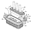
図1~図8は、本発明に係るシールドコネクタの係止構造の一実施形態を示すものである。
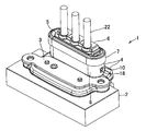
図1の如く、シールドコネクタ1は、機器の導電金属製のケース2にカバー3と共にボルト締めで接続固定されるアルミダイカスト(導電金属)製のシールドシェル4と、シールドシェル4の内側に収容配置される絶縁樹脂製のコネクタハウジング5と、コネクタハウジング5の電線導出側(上側)に装着される合成樹脂製のホルダ6と、シールドシェル4の上部に装着されるシールドリング7とを備えたものである。
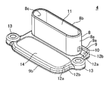
図2の如く、シールドシェル4は、横断面長円形の垂直な環状壁8と、環状壁8の下端に直交して一体に続く鍔部9とで構成されている。環状壁8は、長径側の横断面半円状の左右の湾曲壁部8aと、短径側の平行な前後の真直壁部8bとで構成され、左右の湾曲壁部8aの下部にコネクタハウジング係止用の縦長矩形状の孔部(被係止部)10が設けられている。孔部10は環状壁8内の上下に貫通した空間11に連通している。
鍔部9は、環状壁8に続く後半の枠状部分9aと、後半の枠状部分9aと同一水平面で続く前半の枠状部分9bとで成り、両枠状部分9a,9bは水平な壁部12aと垂直な壁部12bとで縦断面略L字状に形成されると共に、左右に一対のボルト挿通部13を有し、前半の枠状部分9bは横長矩形状の大きな孔部14を有している。
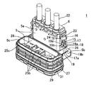
図3,図4の如く、コネクタハウジング5は、後側上部の縦長矩形状の垂直な収容部5aと、収容部5aの下側に一体に続く横長矩形状の水平な収容部5bと、下側の収容部5bに一体に続く前側の垂直な横長矩形環状の収容部5cとで構成されている。
後側上部の収容部5aの左右の垂直な側壁15の外面(符号15で代用)に水平な突出壁16が一体に設けられ、突出壁16の先端から下向きに係止アーム17が垂直に一体に設けられ、係止アーム17は下部に外向きの突起18を有し、突起18は上側の傾斜面18aと下側の水平な係止面18bとを有し、係止アーム17の下端部17aは突起18の下側に短く延長されている。係止アーム17はアーム本体(符号17で代用)と突起18とで構成されている。突出壁16を係止アーム17の一部と見ることも可能である。
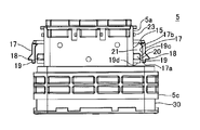
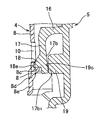
さらに、突出壁16の下側で係止アーム17の内側すなわち撓み方向において、側壁15の外面に、係止アーム17に対するストッパ突部19が一体に設けられ、ストッパ突部19は垂直壁19aと、垂直壁19aの下部に直交する水平壁19bとで成り、垂直壁19aの垂直な外面19c(図4)は係止アーム17の内面17bに近接して対向している。
図4の如く、自由状態の係止アーム17の下端17aはストッパ突部19の下端19dと同一水平面に位置している。係止アーム17の内面17bとストッパ突部19の外面19cとの間の隙間20は、係止アーム17の内面17bとハウジング収容部5aの側壁外面(符号15で代用)との間の隙間21よりもかなり小さく設定されている。本例において、係止アーム17の内面17bとストッパ突部19の外面19cとの間の隙間20は、ストッパ突部19の突出長さの略1/4程度である。
コネクタハウジング5の後側上部の収容部5aの後半上部にホルダ6(図3)が装着され、ホルダ6は例えば電線22の絶縁外皮(符号22で代用)、又は絶縁外皮に外挿された不図示の防水ゴム栓を抜け止め保持し、突出壁16の上側の小突起23に可撓性の係止枠片24を係合させて固定される。電線22の不図示の芯線部は導電金属板のL字状の端子25(図6)の垂直部分25aに圧着接続され、端子25の水平部分25b(図3)は、機器側の不図示の端子にボルト締めで接続される円孔25cを有して、コネクタハウジング5の前側の収容部5c内に突出している。前側の収容部5cは後側下部の収容部5b(図3)の上壁面26と同一水平面の上部段差27を有している。
例えばコネクタハウジング5の後側下部の収容部5bが上下に分割され、前側の収容部5cの後壁28(図3)に横長の端子貫通孔29が設けられ、端子付き電線22が端子25を下にした状態で後側の収容部5a,5bに下側から挿通されて、端子25(図6)がコネクタハウジング5内に組み付けられる。前側の収容部5cの下部側の外周の水平な溝30(図4)には、機器のケース2(図1)の不図示の孔部の内周面に対する防水用の環状のパッキン31(図3)が装着されている。明細書で前後左右上下の方向は説明の便宜上のものであり、必ずしも機器に対するシールドコネクタ1の装着方向と一致するものではない。
図3のコネクタハウジング5に上側から図2のシールドシェル4が装着され(図2のシールドシェル4に下側から図3のコネクタハウジング5が挿入され)、その際、電線22はシールドシェル4の環状壁8内に予め貫通され、図5の如く、コネクタハウジング5の後側上部の収容部5aがシールドシェル4の環状壁8内に挿入収容され、コネクタハウジング5の後側下部の収容部5b(図3)がシールドシェル4の後半の鍔部9aの内側に挿入収容され、コネクタハウジング5の前側の収容部5cの外側上部にシールドシェル4の前半の鍔部9bが装着される。
それと同時に、コネクタハウジング5の後半上部の収容部5aの左右の係止アーム17の突起18がシールドシェル4の環状壁8の左右の孔部10に係合する。図5,図6の如く、突起18は孔部10のほぼ中央に位置し、図5の如く、突起18の前後の端面18dと孔部10の前後の端面10aとの間に若干の隙間を存し、図6の如く、突起18の上下の端面18a,18b(上側の端面は傾斜面18aである)と孔部10の上下の端面10bとの間に若干の隙間を存する。突起18の先端18eは孔部10を貫通して外部に突出する。
図7の如く、コネクタハウジング5にシールドシェル4を上方から装着(外挿)する際に、係止アーム17の突起18の先端18eがシールドシェル4の環状壁8の内壁面(内面)8cに摺接しつつ、係止アーム17が内向きに撓んで、係止アーム17の下端部内面17b1がストッパ突部19の下部外面19cに当接して、係止アーム17のそれ以上の撓みが阻止され、係止アーム17は上側の突出壁16を支点に内向きに傾斜する。
その状態からさらにシールドシェル4の外挿を続けると、係止アーム17が図7の状態よりもさらに内向きに圧縮されつつ、係止アーム17の内面17bが突出壁19の外面19c全体に当接して、係止アーム17の撓みが完全に阻止され、この状態で突起18の先端18eは環状壁8の内壁面8cを外向きに押圧し、突起18が環状壁8の内壁面8cに沿って圧入される。図7においては便宜上、突起18を壁部8にラップさせて圧入状態を示している。
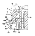
次いで、図8の如く、突起18の先端18eが環状壁8の孔部10に進入し、それと同時に係止アーム17の撓みが解除されて、図6の如く係止アーム17が垂直に復帰し、突起18が大きな係止代で孔部10に完全係合する。図8は、突起18が孔部10に進入を開始した復帰前の半係合の状態を示している。突起18の「半係合」とは、孔部10の下端面10bの内半部に、孔部10の深さのほぼ半分程度の幅で突起18の先端側の係止面18bが係合することを言う。また、「外挿」とは、コネクタハウジング5の外側にシールドシェル4を挿入することを言う。
このように、係止アーム17が撓み動作と圧入動作と復帰動作を順に行うことで、先ず図7における係止アーム17の撓み動作で突起18が内向きに後退して、突起18の先端18eとシールドシェル4の環状壁8の内壁面8cとの摺動摩擦抵抗が減少し(突起18と環状壁8の内壁面8cとのラップ代すなわち圧入代が減少し)、それにより、コネクタハウジング5へのシールドシェル4の組付が低挿入力で容易にスムーズに行われ、且つ突起18の先端18eの削れや潰れ量が少なくて済み、次いで図8における係止アーム17の復帰動作で、突起18の係止面18bと環状壁8の孔部10の下端面10bとのラップ代すなわち係止代が大きく確保されて、大きな係止力でシールドシェル4がコネクタハウジング5に係止(保持)される。
さらに、図6の係止アーム17の完全復帰状態で、例えばシールドシェル4に上向きの抜き方向の力(コネクタハウジング5に下向きの抜け方向の力)が作用した場合に、従来においては係止アーム17が不意に撓んで係止アーム17の突起18がシールドシェル4の孔部10から離脱してしまう場合でも、図8の如く、係止アーム17が撓み途中でストッパ突部19に当接してそれ以上の撓みが阻止されるから、突起18が孔部10に半係合した状態で維持され、突起18が孔部10から離脱することがなく、係止アーム17の係止力が高められて、コネクタハウジング5からのシールドシェル4の抜け出しが確実に防止される。
これらにより、コネクタハウジング5へのシールドシェル4の組付作業性が向上すると共に、シールドコネクタ1を機器に組み付ける前の搬送時等において、コネクタハウジング5からのアルミダイカスト製の重量の嵩むシールドシェル4の抜けが確実に防止される。機器へのシールドコネクタ1の組付後は、ボルト締めでシールドシェル4が機器のケース2(図1)に固定され、コネクタハウジング5の後側下部と前側の各収容部5b,5cがシールドシェル4の鍔部9で上から押さえられるので、シールドシェル4の抜け出しやコネクタハウジング5の抜け出しの心配はない。
図8の如く、シールドシェル4の孔部10の下側に垂直な壁部(環状壁)8が短く続き、垂直な壁部8は傾斜部8dを経て下側の一段大径な垂直な壁部8eに続いている。これは図8の左側の壁部8に限らず、図6の右側の壁部8においても同様である。
コネクタハウジング5にシールドシェル4を外挿する際に、先ず図7の前段階で(図7の状態に至る前に)、係止アーム17の突起18の先端18eが下側の大径な壁部8eの内面に沿って摺接しつつ、係止アーム17が内向きに少し撓み、次いで突起18の先端18eが傾斜部8dの内面をスムーズに摺接し、図7の如く上側の縮径された壁部8の内面8cに沿って摺接しつつ、係止アーム17が内向きに中程度に撓んで、係止アーム17とストッパ突部19との当接状態を得る。このように、係止アーム17の撓み動作が段階的に徐々に行われることで、環状壁8への突起18の圧入動作が徐々に行われて、コネクタハウジング5へのシールドシェル4の組付が一層スムーズに行われる。
図6の如く、孔部10の上側においてホルダ6(図5)の外側でシールドシェル4の上部に薄板金属製のシールドリング7が圧入等で固定される。本例のホルダ6は電線22の絶縁外皮に密着している。電線22に接続された端子25は垂直部25aから水平に折り曲げられ、垂直部25aがコネクタハウジング5の後側上部の収容部5a内に位置し、水平部25bは後側下部の収容部5bを通って前側の収容部5c(図5)内に位置している。
なお、上記実施形態においては、L字状の端子25を用いた例で説明したが、例えば真直な端子(図示せず)を用いる場合は、上側の収容部と下側の収容部と上下の収容部の中間の外向きの鍔部とで成る縦長のコネクタハウジング(図示せず)を用い、上側の収容部から電線22を上向きに導出させ、下側の収容部から電線付き端子のボルト締め用の孔部を有する先端部を突出させ、鍔部と上側の収容部とをシールドシェル(図示せず)の環状壁と鍔部とで覆う構成とし、上記実施形態と同様に、上側の収容部に設けた係止アーム17を撓ませてストッパ突部19に当接させつつ、係止アーム17の突起18を環状壁8の内面8cに圧入させて孔部10に係合させることも可能である。
また、上記実施形態においては、係止アーム17に対してコネクタハウジング5にストッパ突部19を設けたが、これとは逆に係止アーム17の内面17bにストッパ突部(19)を一体に設け、係止アーム17の撓み時にコネクタハウジング5の上側の収容部5aの垂直な壁面15に係止アーム17のストッパ突部(19)を当接させて、それ以上の係止アーム17の撓みを阻止した状態で、係止アーム17の突起18をシールドシェル4の内壁面8cに沿って孔部まで圧入させることも可能である。
この場合、係止アーム17のストッパ突部(19)の形状は、図6の例のストッパ突部19と同様の左右長さ(突出長さ)と上下長さを有するものであることが好ましい。係止アーム17の内面17bと収容部5aの外壁面15との間の隙間21(図4)すなわち突出壁19の突出長さが図6におけるよりも小さい場合は、突起18の突出長さは小さく設定される。係止アーム17の内面17bと収容部5aの外壁面15とを近接させた場合は、ストッパ突部19を設けずに、係止アーム17の内面17bをストッパ部として作用させ、係止アーム17の撓み時に係止アーム17の内面17bを収容部5aの外壁面15に当接させ、その状態で係止アーム17の突起18をシールドシェル4の内面8cに圧入させることも可能である。
また、上記実施形態においては、係止アーム17を下向きに垂下させて係止アーム17の下部に突起18を配置したが、例えば係止アーム18を上向きに立ち上げて係止アーム17の上部に突起18を配置することも可能であり、この場合には、係止アーム17の突起18をシールドシェル4の孔部10ではなく、シールドシェル4の上端4a(図6)の不図示の凹部や段部等(被係止部)に係合させる。
また、本実施形態においては、機器側の端子にシールドコネクタ1の端子25を接続させる機器直付けコネクタの例で説明したが、機器側の端子に限らず、ワイヤハーネス等の相手側コネクタの端子にシールドコネクタ1の端子25をボルト締め等で接続させる場合においても、本実施形態の係止アーム17を撓み途中で停止させて、係止アーム17の突起18をシールドシェル4内に圧入する構成を適用可能である。
本発明に係るシールドコネクタの係止構造は、絶縁性のコネクタハウジングに導電性のシールドシェルを組み付ける際に、係止アームの撓みを小さく抑えて、係止アームの突起を削れ等なくシールドシェルの内面にスムーズに圧入させて、コネクタハウジングへのシールドシェルの組付性を高めると共に、係止アームの突起をシールドシェルの被係止部に係合させた後は、係止アームの不意な撓みを抑えて、コネクタハウジングからのシールドシェルの離脱を確実に防止し、それらにより、シールドコネクタの搬送時等における組立の信頼性を高めるために利用することができる。
1 シールドコネクタ
4 シールドシェル
5 コネクタハウジング
8c 内壁面(内面)
10 孔部(被係止部)
15 側壁(外面)
17 係止アーム
17b 内面
18 突起
19 ストッパ突部
4 シールドシェル
5 コネクタハウジング
8c 内壁面(内面)
10 孔部(被係止部)
15 側壁(外面)
17 係止アーム
17b 内面
18 突起
19 ストッパ突部
Claims (3)
- 絶縁性のコネクタハウジングに外向きの突起付きの可撓性の係止アームが設けられ、該コネクタハウジングに外挿される導電性のシールドシェルに、該突起を係合させる被係止部が設けられ、該被係止部に該突起が半係合した状態で、該係止アームの係止解除方向の撓みが阻止され、また、該コネクタハウジングに該シールドシェルを外挿する際に、該係止アームが撓みつつ、該突起が該シールドシェルの内面に沿って圧入されることを特徴とするシールドコネクタの係止構造。
- 前記係止アームの撓み方向の内面に対向して、前記コネクタハウジングの外面に、該内面を当接させるストッパ突部が設けられたことを特徴とする請求項1記載のシールドコネクタの係止構造。
- 前記コネクタハウジングの外面に対向して、前記係止アームの撓み方向の内面に、該外面に当接するストッパ突部が設けられたことを特徴とする請求項1記載のシールドコネクタの係止構造。
Priority Applications (3)
| Application Number | Priority Date | Filing Date | Title |
|---|---|---|---|
| US13/985,212 US9356398B2 (en) | 2011-02-14 | 2012-02-13 | Lock mechanism of shield connector |
| CN201280008919.4A CN103380546B (zh) | 2011-02-14 | 2012-02-13 | 屏蔽连接器的锁定机构 |
| EP12747723.0A EP2677606B1 (en) | 2011-02-14 | 2012-02-13 | Latching structure for shielded connector |
Applications Claiming Priority (2)
| Application Number | Priority Date | Filing Date | Title |
|---|---|---|---|
| JP2011-028220 | 2011-02-14 | ||
| JP2011028220A JP5680435B2 (ja) | 2011-02-14 | 2011-02-14 | シールドコネクタの係止構造 |
Publications (1)
| Publication Number | Publication Date |
|---|---|
| WO2012111593A1 true WO2012111593A1 (ja) | 2012-08-23 |
Family
ID=46672512
Family Applications (1)
| Application Number | Title | Priority Date | Filing Date |
|---|---|---|---|
| PCT/JP2012/053234 Ceased WO2012111593A1 (ja) | 2011-02-14 | 2012-02-13 | シールドコネクタの係止構造 |
Country Status (5)
| Country | Link |
|---|---|
| US (1) | US9356398B2 (ja) |
| EP (1) | EP2677606B1 (ja) |
| JP (1) | JP5680435B2 (ja) |
| CN (1) | CN103380546B (ja) |
| WO (1) | WO2012111593A1 (ja) |
Cited By (1)
| Publication number | Priority date | Publication date | Assignee | Title |
|---|---|---|---|---|
| TWI896450B (zh) * | 2024-03-25 | 2025-09-01 | 美商莫仕有限公司 | 電連接器及電連接器組合 |
Families Citing this family (10)
| Publication number | Priority date | Publication date | Assignee | Title |
|---|---|---|---|---|
| JP5751875B2 (ja) * | 2011-03-22 | 2015-07-22 | 矢崎総業株式会社 | シールドコネクタ |
| CN104979707B (zh) * | 2014-04-11 | 2018-02-09 | 矢崎总业株式会社 | 连接器 |
| JP6734836B2 (ja) * | 2017-12-20 | 2020-08-05 | 矢崎総業株式会社 | コネクタの防水構造 |
| JP1622367S (ja) * | 2018-06-21 | 2019-01-21 | ||
| USD892058S1 (en) * | 2018-10-12 | 2020-08-04 | Amphenol Corporation | Electrical connector |
| USD908633S1 (en) | 2018-10-12 | 2021-01-26 | Amphenol Corporation | Electrical connector |
| TWI855075B (zh) | 2019-05-20 | 2024-09-11 | 美商安芬諾股份有限公司 | 連接器模組、連接器、電子組件、電連接器以及連接器模組的薄片 |
| JP7362708B2 (ja) * | 2021-10-11 | 2023-10-17 | 矢崎総業株式会社 | シールドコネクタ |
| USD1068685S1 (en) | 2021-12-14 | 2025-04-01 | Amphenol Corporation | Electrical connector |
| USD1067191S1 (en) | 2021-12-14 | 2025-03-18 | Amphenol Corporation | Electrical connector |
Citations (2)
| Publication number | Priority date | Publication date | Assignee | Title |
|---|---|---|---|---|
| JPH037272U (ja) * | 1989-06-12 | 1991-01-24 | ||
| JPH1140272A (ja) * | 1997-07-04 | 1999-02-12 | Molex Inc | 金属シェル付コネクタ |
Family Cites Families (18)
| Publication number | Priority date | Publication date | Assignee | Title |
|---|---|---|---|---|
| US4711507A (en) * | 1985-10-07 | 1987-12-08 | Thomas & Betts Corporation | Electrical connector and latching apparatus therefor |
| US5518421A (en) | 1993-01-26 | 1996-05-21 | The Whitaker Corporation | Two piece shell for a connector |
| US5525074A (en) * | 1993-07-12 | 1996-06-11 | Yazaki Corporation | Panel mounted connector |
| JP3074432B2 (ja) * | 1994-01-27 | 2000-08-07 | 矢崎総業株式会社 | ロック付きコネクタハウジング |
| WO2000004609A1 (en) * | 1998-07-15 | 2000-01-27 | Thomas & Betts International, Inc. | Connector for airbag gas generator |
| TW392935U (en) * | 1998-08-27 | 2000-06-01 | Hon Hai Prec Ind Co Ltd | Electric connector structure |
| JP2001023729A (ja) * | 1999-07-02 | 2001-01-26 | Yazaki Corp | コネクタ |
| US6146182A (en) * | 1999-08-13 | 2000-11-14 | Hon Hai Precision Ind. Co., Ltd. | Electrical connector with latching means |
| JP2001326034A (ja) | 2000-05-16 | 2001-11-22 | Furukawa Electric Co Ltd:The | シールド機能を備えた電気コネクタ |
| US20020155746A1 (en) * | 2001-04-19 | 2002-10-24 | Simpson Jeffrey S. | Cable assembly latch |
| DE10356566B3 (de) * | 2003-12-04 | 2005-07-21 | Airbus Deutschland Gmbh | Verriegelbare Steckverbindung |
| JP2006216434A (ja) * | 2005-02-04 | 2006-08-17 | Yazaki Corp | ロックコネクタ |
| JP4579021B2 (ja) * | 2005-03-23 | 2010-11-10 | ヒロセ電機株式会社 | 電気コネクタ |
| JP4278674B2 (ja) | 2006-10-17 | 2009-06-17 | ヒロセ電機株式会社 | 電気コネクタ |
| JP4999175B2 (ja) * | 2007-10-03 | 2012-08-15 | 矢崎総業株式会社 | シールドコネクタ |
| JP5310010B2 (ja) * | 2009-01-14 | 2013-10-09 | 住友電装株式会社 | シールドコネクタ |
| JP5206480B2 (ja) | 2009-02-23 | 2013-06-12 | 住友電装株式会社 | コネクタ装置 |
| JP5304676B2 (ja) * | 2010-02-05 | 2013-10-02 | 住友電装株式会社 | シールドコネクタ |
-
2011
- 2011-02-14 JP JP2011028220A patent/JP5680435B2/ja active Active
-
2012
- 2012-02-13 CN CN201280008919.4A patent/CN103380546B/zh active Active
- 2012-02-13 WO PCT/JP2012/053234 patent/WO2012111593A1/ja not_active Ceased
- 2012-02-13 US US13/985,212 patent/US9356398B2/en active Active
- 2012-02-13 EP EP12747723.0A patent/EP2677606B1/en active Active
Patent Citations (2)
| Publication number | Priority date | Publication date | Assignee | Title |
|---|---|---|---|---|
| JPH037272U (ja) * | 1989-06-12 | 1991-01-24 | ||
| JPH1140272A (ja) * | 1997-07-04 | 1999-02-12 | Molex Inc | 金属シェル付コネクタ |
Non-Patent Citations (1)
| Title |
|---|
| See also references of EP2677606A4 * |
Cited By (1)
| Publication number | Priority date | Publication date | Assignee | Title |
|---|---|---|---|---|
| TWI896450B (zh) * | 2024-03-25 | 2025-09-01 | 美商莫仕有限公司 | 電連接器及電連接器組合 |
Also Published As
| Publication number | Publication date |
|---|---|
| US9356398B2 (en) | 2016-05-31 |
| EP2677606A1 (en) | 2013-12-25 |
| EP2677606A4 (en) | 2014-07-23 |
| CN103380546B (zh) | 2015-09-30 |
| EP2677606B1 (en) | 2019-04-10 |
| CN103380546A (zh) | 2013-10-30 |
| JP5680435B2 (ja) | 2015-03-04 |
| JP2012169102A (ja) | 2012-09-06 |
| US20130316579A1 (en) | 2013-11-28 |
Similar Documents
| Publication | Publication Date | Title |
|---|---|---|
| JP5680435B2 (ja) | シールドコネクタの係止構造 | |
| CN103579870B (zh) | 连接器 | |
| JP5056444B2 (ja) | 電気接続箱 | |
| WO2017208779A1 (ja) | シールドコネクタ | |
| CN109037994A (zh) | 连接器 | |
| JP2009277544A (ja) | 基板用シールドコネクタ | |
| JP4605136B2 (ja) | 電気接続箱 | |
| KR20130124568A (ko) | 커넥터 | |
| JP2011101502A (ja) | 電気接続箱 | |
| JP5999440B2 (ja) | コネクタ | |
| JP5585106B2 (ja) | コネクタ装置 | |
| JP2010049844A (ja) | コネクタ及び端子金具 | |
| JP2012094289A (ja) | 電線カバー及びコネクタ | |
| JP5780433B2 (ja) | コネクタ | |
| JP2012054206A (ja) | コネクタ | |
| JP2013258067A (ja) | コネクタ | |
| JP2012169219A (ja) | シールドコネクタ | |
| JP4930418B2 (ja) | コネクタ | |
| JP5672192B2 (ja) | シールドコネクタ | |
| JP2005317357A (ja) | 基板用コネクタ、及びケース付き基板用コネクタ | |
| JP2014183002A (ja) | コネクタ | |
| JP2013004359A (ja) | コネクタホルダ | |
| JP5136274B2 (ja) | 電気接続箱、及びそれを備えた電気ボックス | |
| JP2005310585A (ja) | 機器用コネクタ | |
| JP5206530B2 (ja) | コネクタ |
Legal Events
| Date | Code | Title | Description |
|---|---|---|---|
| 121 | Ep: the epo has been informed by wipo that ep was designated in this application |
Ref document number: 12747723 Country of ref document: EP Kind code of ref document: A1 |
|
| WWE | Wipo information: entry into national phase |
Ref document number: 13985212 Country of ref document: US |
|
| NENP | Non-entry into the national phase |
Ref country code: DE |
|
| WWE | Wipo information: entry into national phase |
Ref document number: 2012747723 Country of ref document: EP |