WO2012111649A1 - 連続鋳造機に用いる鋳片表面の温度測定装置 - Google Patents
連続鋳造機に用いる鋳片表面の温度測定装置 Download PDFInfo
- Publication number
- WO2012111649A1 WO2012111649A1 PCT/JP2012/053351 JP2012053351W WO2012111649A1 WO 2012111649 A1 WO2012111649 A1 WO 2012111649A1 JP 2012053351 W JP2012053351 W JP 2012053351W WO 2012111649 A1 WO2012111649 A1 WO 2012111649A1
- Authority
- WO
- WIPO (PCT)
- Prior art keywords
- slab
- continuous casting
- casting machine
- thermometer
- arm member
- Prior art date
- Legal status (The legal status is an assumption and is not a legal conclusion. Google has not performed a legal analysis and makes no representation as to the accuracy of the status listed.)
- Ceased
Links
Images




Classifications
-
- B—PERFORMING OPERATIONS; TRANSPORTING
- B22—CASTING; POWDER METALLURGY
- B22D—CASTING OF METALS; CASTING OF OTHER SUBSTANCES BY THE SAME PROCESSES OR DEVICES
- B22D11/00—Continuous casting of metals, i.e. casting in indefinite lengths
- B22D11/16—Controlling or regulating processes or operations
-
- B—PERFORMING OPERATIONS; TRANSPORTING
- B22—CASTING; POWDER METALLURGY
- B22D—CASTING OF METALS; CASTING OF OTHER SUBSTANCES BY THE SAME PROCESSES OR DEVICES
- B22D11/00—Continuous casting of metals, i.e. casting in indefinite lengths
- B22D11/16—Controlling or regulating processes or operations
- B22D11/18—Controlling or regulating processes or operations for pouring
- B22D11/181—Controlling or regulating processes or operations for pouring responsive to molten metal level or slag level
- B22D11/182—Controlling or regulating processes or operations for pouring responsive to molten metal level or slag level by measuring temperature
-
- B—PERFORMING OPERATIONS; TRANSPORTING
- B22—CASTING; POWDER METALLURGY
- B22D—CASTING OF METALS; CASTING OF OTHER SUBSTANCES BY THE SAME PROCESSES OR DEVICES
- B22D11/00—Continuous casting of metals, i.e. casting in indefinite lengths
- B22D11/16—Controlling or regulating processes or operations
- B22D11/20—Controlling or regulating processes or operations for removing cast stock
- B22D11/201—Controlling or regulating processes or operations for removing cast stock responsive to molten metal level or slag level
- B22D11/202—Controlling or regulating processes or operations for removing cast stock responsive to molten metal level or slag level by measuring temperature
-
- G—PHYSICS
- G01—MEASURING; TESTING
- G01J—MEASUREMENT OF INTENSITY, VELOCITY, SPECTRAL CONTENT, POLARISATION, PHASE OR PULSE CHARACTERISTICS OF INFRARED, VISIBLE OR ULTRAVIOLET LIGHT; COLORIMETRY; RADIATION PYROMETRY
- G01J5/00—Radiation pyrometry, e.g. infrared or optical thermometry
- G01J5/02—Constructional details
- G01J5/05—Means for preventing contamination of the components of the optical system; Means for preventing obstruction of the radiation path
Definitions
- the present invention relates to a temperature measuring device for measuring the temperature of the surface of a slab in a secondary cooling zone of a continuous casting machine.
- a continuous casting machine that manufactures a slab has a mold and a secondary cooling zone that is disposed downstream of the mold and cools the slab drawn from the mold while being conveyed in the drawing direction (casting direction). .
- this secondary cooling zone it is arranged on the front side and the back side of the slab drawn out from the mold, respectively, and is arranged between the roll that sandwiches and conveys (supports) the slab from the thickness direction and the roll that is adjacent in the drawing direction. And a number of cooling nozzles for cooling the slab being conveyed by the roll.
- the roll provided in the secondary cooling zone may have a plurality of rolls integrated with a roll segment or may not use a roll segment. In the secondary cooling zone described above, it is important to cool the slab to solidify, and it is also important to prevent quality defects such as cracking of the slab due to overcooling. Therefore, it is important to measure the temperature of the slab surface.
- the temperature measurement on the surface of the slab is not limited to a single temperature measurement, and recently, a steady temperature measurement has been started as a quality control index. In addition, with the improvement of manufacturing quality, improvement in measurement accuracy and measurement over the entire width direction have begun to be required.
- the following invention is disclosed with respect to the said subject.
- Patent Document 1 in order to suppress the influence of water vapor when measuring the surface temperature of the slab, the spraying of the secondary cooling water to the temperature measurement range of the slab surface is temporarily interrupted, and the secondary cooling water Describes a method for measuring the surface temperature of a slab in a state in which the generation of water vapor due to is suppressed.
- Patent Document 2 describes a method of suppressing the influence of water vapor or the like when measuring the surface temperature of a slab by enclosing a measurement portion with a hood and air purging the inside of the hood.
- Cited Document 1 the temperature measurement of the slab is performed in a place where water vapor is adversely affected unless spraying of the secondary cooling water is interrupted. Therefore, during the period when spraying is not interrupted, condensation on the thermometer and dust adhesion occur, which adversely affects measurement accuracy.
- thermometer in the situation where the thermometer is placed close to the continuous casting machine, the maintenance of the thermometer must be stopped for maintenance such as cleaning of the thermometer, or the maintenance of the roll and the cooling nozzle (the roll from the continuous casting machine). And removal of the cooling nozzle).
- a thermometer is installed at an upper position on one side in the width direction of the slab, and the temperature measurement of the slab surface is performed obliquely above the slab (a position different from the upper part of the slab surface). Therefore, it becomes difficult to distinguish the edge portion of the slab located on the side opposite to the thermometer installation position and the surrounding environment. Therefore, the width of the slab cannot be accurately determined, and the position of the edge portion of the slab cannot be specified. Therefore, it becomes difficult to measure the temperature of the edge portion, and accurate temperature measurement cannot be performed.
- thermometer In the method described in Patent Document 2, it is necessary to install the hood at a position close to the slab. Therefore, the thermometer needs to be structurally integrated with the roll segment. Therefore, if the thermometer fails during operation of the continuous casting machine, the thermometer cannot be removed from the roll segment, and the thermometer cannot be repaired. Moreover, it is necessary to install in the roll segment a device that performs an air purge toward the hood or slab. For this reason, for example, when the roll segment is replaced, it is necessary to remove and attach each time, and a production loss of the slab is generated due to the extension of the replacement time. In addition, if the hood installed at the part where the slab temperature is measured falls from the fixed part for some reason, the hood and the slab may come into contact with each other, causing oysters on the slab. .
- thermometer In order to perform accurate temperature measurement including the edge, it is desirable to install the thermometer above the slab, but water vapor and dust that adversely affects measurement accuracy are likely to adhere to the thermometer. Therefore, it is necessary to suppress these.
- the surface temperature of the slab in the steady state cannot be accurately measured.
- the edge temperature Cannot be measured accurately.
- the measurement part is surrounded by a hood, there is a problem that although the influence of water vapor can be reduced, maintenance becomes difficult. That is, a slab surface temperature measuring device that achieves long-term maintenance of measurement accuracy and is excellent in maintainability has not yet been provided.
- An object of the present invention is to provide a slab surface temperature measuring device used in a continuous casting machine capable of simplifying the maintenance work of the continuous casting machine.
- the slab surface temperature measuring device used in the continuous casting machine is the secondary cooling zone of the continuous casting machine, and is the width of the slab that is drawn from the mold and conveyed by the roll.
- a temperature measuring device for measuring the surface temperature of part or all of the direction A support member installed on a side of a roll support part for rotatably supporting the roll; an arm member whose base part is rotatably attached to the support member; and provided at a tip part of the arm member, A radiation thermometer in which a light receiving port can be arranged at a height position of 1.0 m to 4.5 m from the surface of the slab.
- the arm member is composed of a plurality of short arms, and the short arms adjacent to each other are connected via a connecting portion. And may be connected so as to be bent.
- At least one of the short arms may have a telescopic mechanism that allows the length to be adjusted.
- the arm member may have an expansion / contraction mechanism whose length is adjustable.
- the apparatus for measuring the temperature of the slab surface used in the continuous casting machine includes a support member installed on the side of the roll support portion, an arm member having a base attached to the support member, and the arm member. And a radiation thermometer in which a light receiving port can be arranged at a height of 1.0 to 4.5 m from the surface of the slab.
- a radiation thermometer is installed at the tip of the arm member that is pivotally mounted, so that it can be supported, for example, during maintenance of a continuous casting machine (for example, maintenance of a roll or piping for secondary cooling water).
- a continuous casting machine for example, maintenance of a roll or piping for secondary cooling water.
- the radiation thermometer can be moved (withdrawn), so that maintenance is not disturbed.
- maintenance such as cleaning of the radiation thermometer can be performed without stopping the continuous casting machine. That is, by adopting the above aspect, the influence of water vapor or the like that reduces the measurement accuracy of the surface temperature of the slab is suppressed, further prevented, and the maintainability of the thermometer during continuous casting is improved. It becomes possible to simplify the maintenance work of the casting machine.
- the arm member may be composed of a plurality of short arms, and adjacent short arms may be connected via a connecting portion so as to be foldable.
- the radiation thermometer when the radiation thermometer is moved, not only the entire arm member is rotated about the support member, but also the adjacent short arm can be bent.
- the radiation thermometer can be easily moved from the inside of the continuous casting machine above the slab surface to the outside of the continuous casting machine. Can be evacuated.
- by changing the bending angle or the like of adjacent short arms for example, measuring the surface temperature near the center in the width direction of the slab at different positions in the drawing (casting) direction of the slab. You can also.
- the arm member or one or more of the plurality of short arms may be provided with a telescopic mechanism that allows the length to be adjusted.
- options for a method of retracting the radiation thermometer from the continuous casting machine to the outside of the continuous casting machine and a method of changing the temperature measurement position on the slab surface increase.
- the easiness of the radiation thermometer retracting operation and the position changing operation is increased, and the radiation thermometer retracting operation and the position changing operation in consideration of the surrounding environment (for example, a structure) of the continuous casting machine can be performed.
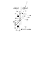
- a slab surface temperature measuring device (hereinafter also simply referred to as a temperature measuring device) 10 used in a continuous casting machine is a two-piece continuous casting machine 11. This is a device for measuring the surface temperature in the width direction of the slab 13 drawn from a mold (not shown) in the next cooling zone 12 and conveyed by a roll (not shown).
- the continuous casting machine 11 in which the temperature measuring device 10 is installed is a vertical bending type or a curved bending type continuous casting machine, but is not limited thereto, and may be, for example, a vertical continuous casting machine. Details will be described below.
- the secondary cooling zone 12 is arranged on the front side and the back side of the slab 13 drawn out from the mold, and is adjacent to the roll that sandwiches and transports the slab 13 from the thickness direction and the drawing direction (hereinafter also referred to as the casting direction).
- a large number of cooling nozzles are provided between the matching rolls and cool the slab 13.
- the roll provided in the secondary cooling zone 12 is integrally formed with a roll segment (an example of a roll support portion) 14 that rotatably supports a plurality of rolls, and the roll segment 14 extends in the casting direction of the slab 13.
- a plurality are arranged at intervals.
- Roll maintenance for example, work for removing the roll from the continuous casting machine 11 and installation work for the continuous casting machine 11 are performed for each roll segment 14.
- the roll may be configured without a plurality of rolls having an integral structure.
- the work for removing the roll from the continuous casting machine and the work for attaching the roll to the continuous casting machine are performed individually for each roll support portion to which one roll (including a cooling nozzle) is attached.
- the temperature measuring device 10 includes a support (an example of a support member) 15 installed on the side of the roll segment 14, an arm member 17 having a base (rotating unit) 16 rotatably attached to the support 15, an arm It has a radiation thermometer (hereinafter also simply referred to as a thermometer) 19 provided at the front end portion (temperature measuring portion) 18 of the member 17.
- the support column 15 is provided upright in a passage 20 provided outside the continuous casting machine 11 (outside the continuous casting machine) along the side of the roll segment 14, that is, along the casting direction of the slab 13.
- the support member is not limited to the support as long as the thermometer 19 can be disposed at the target height position.
- the side of the roll segment 14 described above means the side of the roll segment 14 (cast piece 13) when the cast piece 13 to be conveyed is viewed in plan. Therefore, the installation position of the support column 15 is not limited to the above-described passage 20. That is, as long as it is other than the roll segment 14 (other than the main body of the continuous casting machine 11), for example, a frame of the continuous casting machine 11 may be used.
- the distance of the support column 15 from the roll segment 14 is not particularly limited as long as the arm member 17 rotates and the thermometer 19 can be disposed and retracted as described later.
- the arm member 17 is provided in a direction orthogonal to the support column 15 and is made of, for example, a steel material.
- the arm member 17 may have a stepped shape of one step or two or more steps in which a central portion in the longitudinal direction is partially bent in a plan view.
- the shape of the arm member 17 By setting the shape of the arm member 17, when the arm member 17 is rotated (turned) around the support column 15, the surrounding environment of the continuous casting machine 11, for example, a structure 21 such as a segment replacement crane (for example, , A restriction on movement of the arm member 17 due to the pillars, etc.)
- the shape of the arm member is not limited to the above-described shape, and may be, for example, an “L” shape, a “V” shape, or an arc shape in plan view, depending on the surrounding environment of the continuous casting machine 11. You can also.
- the base 16 of the arm member 17 is attached to the support column 15 by, for example, a configuration in which a rotation shaft is provided on the arm member and the rotation shaft is rotatably attached to the support column, or a rotation shaft is provided on the support column.
- This can be implemented by a configuration in which the base portion of the arm member is rotatably attached to the moving shaft.
- the rotation of the arm member 17 with respect to the support column 15 is manually performed by an operator, for example, but it can also be automatically performed by a control unit provided with a driving means in the arm member.
- the arm member may further be provided with a telescopic mechanism that allows the length to be adjusted.
- expansion / contraction mechanism examples include a conventionally known slide type in which the arm member is reciprocally movable along the longitudinal direction with respect to the support column, and a conventionally known bellows type in which the length of the arm member is expanded / contracted.
- a conventionally known slide type in which the arm member is reciprocally movable along the longitudinal direction with respect to the support column
- bellows type in which the length of the arm member is expanded / contracted.
- the slab 13 is horizontally conveyed in the above-described rotation region of the arm member 17 (hereinafter also referred to as a rotation region). It becomes a position and is in a plane parallel to the surface of the slab 13.
- the installation position of the temperature measuring device 10 is set to the upstream side portion of the secondary cooling zone 12 (closer to the mold side)
- the slab is conveyed in a curved state.
- the moving region is in a plane that obliquely intersects the surface of the slab 13.
- the rotation region of the arm member is not limited to this as long as the arm member can move.
- the rotation region of the arm member can be in a plane orthogonal to the slab surface.
- the arm member can be rotated in a direction away from or closer to the surface of the slab by disposing the rotation center of the rotation shaft provided on the arm member or the column in parallel with the casting direction.
- the radiation thermometer 19 for example, a conventionally known thermometer that detects thermal radiant energy radiated from a high-temperature object in a non-contact manner can be used.
- the light receiving port of the radiation thermometer 19 is disposed at a height position of 1.0 m or more and 4.5 m or less from the surface of the slab 13.
- the arrangement height position of the light receiving opening is set to 1.0 m or more from the surface of the slab 13.
- the upper end of the roll segment may reach a height position of less than 1 m from the slab surface. In that case, when the thermometer is swung, the thermometer contacts the roll segment and cannot be moved to the measurement position. In order to avoid this contact with certainty, it is preferably 1.3 m or more from the surface of the slab 13, more preferably 1.5 m or more from the surface.
- the gap between adjacent roll segments that is, the gap for measuring the temperature of the cast slab is very narrow, for example, 30 to 200 mm.
- the temperature of the roll, not the slab will be measured because the fixed angle of the thermometer is slightly shifted.
- the arrangement height position of the light receiving opening is set to 4.5 m or less from the surface of the slab 13.
- the gap is similar. However, if it exceeds 3.5 m, the operability during the rotation of the thermometer is lowered, so it is preferable to set it to 3.5 m or less.
- the arrangement height position of the light receiving opening from the surface of the slab 13 can be adjusted by changing the height (length) of the support column 15.
- an elevating means is provided on the support column to increase the height of the support column. It can also be adjusted by adjusting it.
- the installation position of the thermometer 19 is not particularly limited as long as it is above the surface of the slab 13, that is, a position overlapping with the slab 13 in plan view, but is near the center of the slab 13 in the width direction, that is, 300 mm from the center position. It is desirable to set the position above the area within.
- the surface temperature of the slab 13 is facilitated, and the high temperature portion of the slab 13 and the low temperature portion deviated from the slab 13 are obtained. It becomes easy to compare with. In measurement from diagonally above, it becomes difficult to distinguish the edge portion of the slab located on the side opposite to the thermometer installation position and the surrounding environment, and accurate temperature measurement cannot be performed.
- the width of the measurement field of view also changes.
- the width of castable slabs is usually over 1 m.
- the edge part position of the slab 13 can be decided clearly, and it can confirm easily that the temperature measurement position is the slab 13.
- a base for tilting the thermometer 19 is provided at the tip of the arm member 17, and the thermometer 19 is provided on the base. It is good to attach.
- the thermometer 19 can be tilted to adjust the temperature measurement position and the temperature measurement range (including fine adjustment).
- the thermometer 19 may be capable of reciprocating along the longitudinal direction of the arm member.
- the temperature measuring device may be provided with means for performing an air purge toward the light receiving port of the thermometer (for example, the wind speed is 2 to 10 m / sec). Thereby, the error at the time of temperature measurement can be reduced, and the temperature measurement accuracy can be improved.
- FIGS. 1A and 1B A method of measuring the surface temperature of the slab 13 using the slab surface temperature measuring device 10 used in the continuous casting machine according to one embodiment of the present invention will be described with reference to FIGS. 1A and 1B.
- the struts are arranged so that the thermometer 19 is positioned near the center in the width direction of the slab 13 and between the adjacent roll segments 14.
- the arm member 17 is rotated around 15 (clockwise in FIG. 1A).
- the height of the support column 15 is adjusted so that the light receiving port of the thermometer 19 is located at a height position of 1.0 m or more and 4.5 m or less from the surface of the cast piece 13 conveyed in the casting direction.
- the surface temperature in the width direction of the slab 13 can be measured in the secondary cooling zone 12 while the slab 13 drawn from the mold is conveyed in the casting direction.
- the surface temperature of the slab may be a part in the width direction or the entire width direction (full width).
- the distance between the surface of the slab 13 and the light receiving port is within a range in which the temperature of the slab 13 can be measured, and adverse effects such as water vapor are suppressed. Further, it can be sufficiently separated to a position where it can be prevented. Since the thermometer 19 is 1 m or more away from the surface of the slab, the adhesion of water vapor and dust to the light receiving opening is suppressed. However, when the thermometer 19 is used for a long time or fails, the thermometer 19 is cleaned. And maintenance is required. In this case, as shown in FIG.
- the arm member 17 is rotated in the opposite direction to the above-described arrangement centering on the support column 15 (counterclockwise in FIG. 1B), and the thermometer 19 is moved to the width of the continuous casting machine 11. It moves to the maintenance possible position of the thermometer 19 which is the direction end. Thereby, it is not necessary to stop the continuous casting machine 11 every time the thermometer 19 is maintained, and the thermometer 19 can be maintained at all times.
- the use of the continuous casting machine 11 also requires maintenance of the continuous casting machine 11 (for example, maintenance of pipes for rolls and nozzles for cooling water).
- the thermometer 19 is disposed above the surface of the cast slab 13, and as such, it becomes an obstacle during the maintenance of the continuous casting machine 11 and makes maintenance difficult. In some cases. Therefore, as shown in FIG. 1B, the thermometer 19 is moved by rotating the arm member 17 around the support column 15. Thereby, the maintenance work of the continuous casting machine 11 can be simplified. After the maintenance of the thermometer 19 and the continuous casting machine 11 is completed, the thermometer 19 is placed in the vicinity of the center portion in the width direction of the slab 13 and between the adjacent roll segments 14 by a procedure reverse to the procedure described above. Then, the surface temperature of the slab 13 is measured.
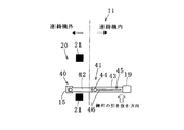
- a slab surface temperature measuring device (hereinafter also simply referred to as a temperature measuring device) 30 used in the continuous casting machine according to the first modification will be described with reference to FIGS. 2A to 2C.
- the same members as those of the temperature measuring apparatus 10 described above are denoted by the same reference numerals, and detailed description thereof is omitted.
- the arm member 31 of the temperature measuring device 30 is composed of a plurality of short arms 32 and 33 (two here, but three or more).
- the adjacent short arm 32 on the base side and the short arm 33 on the front side are connected via a connecting portion 34 so as to be foldable.
- the short arm 32 and the short arm 33 that are adjacent to each other are bent manually by an operator, for example.
- the arm member may be provided with a driving means and automatically controlled by the control unit.
- the shape of the arm member 31 can be not only a straight shape (“I” shape) in a plan view but also an “L” shape, a “V” shape, or the like.
- the arm member 17 of the temperature measuring device 10 In order to satisfy the rotational radius of the arm member 17 of the temperature measuring device 10 in a state where the short arm 32 and the short arm 33 of the arm member 31 are arranged at right angles (that is, “L” shape), the arm member 17 is linear.
- the length of the arm member 31 is the sum of the distance from the center of rotation of the support column 15 to the side surface of the cast piece and 1.1 m.
- the arm member 17 of the temperature measuring device 10 shown in FIG. 1A and FIG. 1B does not have a connecting portion that can be bent.
- the arm member 17 is swung to retract the thermometer 19 out of the continuous casting machine 11 where maintenance is easy, if various devices are provided around the continuous casting machine 11 and are very narrow, The arm member 17 collides with the structure 21 and cannot be retracted.
- the arm member 31 is composed of a plurality of short arms 32 and 33, and these are configured to be bendable so that the thermometer 19 can be easily maintained even in a confined space. Can be saved.
- thermometer 19 Before retraction of the thermometer 19, that is, in FIG. 2A, the thermometer 19 is disposed in the vicinity of the center portion in the width direction of the slab 13 and at an upper position between the adjacent roll segments 14, and the surface of the slab in the width direction. The temperature is being measured. At this time, the arm member 31 is linear, but may be bent into an “L” shape, a “V” shape, or the like according to the temperature measurement position.
- the arm member 31 is rotated around the support column 15 in the direction in which the thermometer 19 faces the outside of the continuous casting machine 11 (counterclockwise in FIG. 2B). .
- the connecting portion 34 that connects the short arms 32 and 33 rotates the arm member 31 to a position outside the continuous casting machine 11 in plan view.
- the short arm 33 on the front side with the connecting portion 34 as the center is rotated in the direction in which the thermometer 19 is directed to the outside of the continuous casting machine 11 (counterclockwise in FIG. 2C).
- the shape of 31 is bent into a “V” shape in plan view.
- the short arm 33 is rotated to a position where the thermometer 19 and the short arm 33 on the front side are out of the continuous casting machine 11 in plan view.
- the support column 15 and the arm member 31 of the temperature measuring device 30 constitute a retracting means for the thermometer 19.
- thermometer 19 With the above configuration, the retraction of the thermometer 19 to the outside of the continuous casting machine 11 can be ensured while preventing the arm member 31 (or the thermometer 19) from colliding with the structure 21. Therefore, the maintainability of the thermometer 19 is further improved as compared with the case where it is retracted to the end portion in the width direction. Furthermore, since the thermometer 19 can be retracted out of the continuous casting machine 11, maintenance such as installation / removal of rolls of the continuous casting machine 11 and secondary cooling-related equipment is facilitated. Depending on the content of the maintenance, it may be retracted to the end in the width direction without being retracted to the outside of the continuous casting machine.
- the arm member 31 is configured to be foldable, even if the thermometer 19 is moved upstream or downstream in the casting direction, for example, by changing the turning radius of the arm member 31, the temperature The total 19 can be arranged at the position of the movement destination so as to be near the center in the width direction of the slab 13 and above the adjacent roll segments 14.
- the support column 15 and the arm member 31 of the temperature measuring device 30 constitute not only the retracting means of the thermometer 19 but also the position changing means. Therefore, even if the casting speed is changed, it is possible to measure the temperature of the slab surface at a position where the cooling time of the slab is constant after the mold exit side. Therefore, the slab surface temperature measuring device 30 used in the continuous casting machine according to the first modification is useful for improving the quality of the slab.
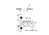
- a slab surface temperature measuring device (hereinafter also simply referred to as a temperature measuring device) 40 used in a continuous casting machine according to a second modification will be described.
- the same members as those of the temperature measuring apparatus 10 described above are denoted by the same reference numerals, and detailed description thereof is omitted.
- the arm member 41 of the temperature measuring device 40 is composed of a plurality of (herein, two, but three or more) short arms 42, 43, and the adjacent proximal short arm 42 and the distal short arm.
- the arm 43 is connected via a connecting portion 44 so as to be bent.
- the short arm 43 on the front side is provided with an expansion / contraction mechanism 45 whose length is adjustable.
- the extension / contraction mechanism may be provided only on the short arm on the base side, or may be provided on both (two or more) short arms.
- the telescopic mechanism 45 is configured by a conventionally known slide type in which the front-side short arm 43 is reciprocally movable along the longitudinal direction with respect to the distal end portion of the base-side short arm 42. Specifically, the connecting portion 44 attached to the distal end portion of the proximal short arm 42 moves in a long hole (long groove) 46 formed along the longitudinal direction of the distal short arm 43.
- the expansion / contraction mechanism can be configured by the above-described conventionally known bellows type, but is not limited thereto.
- the movement of the short arm 43 on the front side is manually performed by an operator, for example. However, the short arm can be provided with a driving means and automatically performed by the control unit.
- the bending of the adjacent short arm 42 on the base side and the short arm 43 on the front side is performed manually by an operator, for example.
- the arm member may be provided with a driving means and automatically performed by the control unit.
- the shape of the arm member 41 can be made linear (“I” shape), “L” shape, “V” shape, etc. in plan view, and further compact. I can plan.
- thermometer 19 Before the thermometer 19 is retracted, that is, in FIG. 3A, the thermometer 19 is arranged in the vicinity of the center portion in the width direction of the slab 13 and at an upper position between the adjacent roll segments 14. The surface temperature is measured. At this time, the arm member 41 is linear, but may be “L” -shaped, “V” -shaped, or the like.
- the arm member 41 When retracting the thermometer 19, first, as shown in FIG. 3B, the arm member 41 is rotated around the support column 15 in the direction in which the connecting portion 44 goes out of the continuous casting machine 11 (counterclockwise in FIG. 3B). .
- the connecting member 44 that connects the short arms 42 and 43 rotates the arm member 41 to a position that is outside the continuous casting machine 11 in plan view.
- the front-side short arm 43 is rotated with respect to the base-side short arm 42 so that the front-side short arm 43 is in a direction perpendicular to the casting direction of the slab (in FIG. 3B). clockwise).
- the front-side short arm 43 is moved in a direction in which the thermometer 19 and the front-side short arm 43 move from the inside of the continuous casting machine 11 to the outside of the continuous casting machine 11 in plan view. Is slid with respect to the distal end portion of the proximal short arm 42 (left side in FIG. 3C). At this time, the short arm 43 is moved to a position where the short arm 43 on the front side is out of the continuous casting machine 11 in plan view. Then, as shown in FIG. 3D, the thermometer 19 rotates the short arm 42 on the base side around the support column 15 in a direction away from the continuous casting machine 11 (counterclockwise in FIG. 3D).
- thermometer 19 rotates the short arm 42 to a position outside the continuous casting machine 11 in plan view.
- the support column 15 and the arm member 41 of the temperature measuring device 40 constitute a retracting means for the thermometer 19 and further a position changing means.
- thermometer With the temperature measuring device 10 and the temperature measuring device 30 described above, the thermometer can be retracted outside the continuous casting machine 11.
- the provision of the expansion / contraction mechanism 45 as in the temperature measuring device 40 increases the options for the retracting means of the thermometer 19 (how to move and how to move the arm member to be retracted), so that the retracting operation according to the surrounding environment can be performed. It becomes possible.
- the slab surface temperature measuring device used in the continuous casting machine according to the present embodiment the influence of water vapor and the like that reduce the measurement accuracy of the surface temperature of the slab is suppressed, and further prevented.
- the maintainability of the thermometer during continuous casting can be improved, and the maintenance work of the continuous casting machine can be simplified.
- thermometer light receiving port thermometer light receiving port
- error temperature measurement error
- the measurement was made about one month after cleaning the light receiving opening, and about 30 times in two years.
- the result is shown in FIG.
- the temperature measurement error shown in FIG. 4 is obtained by comparing the batch measurement value with the thermocouple with the measurement value of the radiation thermometer, and “(batch measurement value with the thermocouple) ⁇ (measurement value of the radiation thermometer)”. It was.
- the result is divided into the case of blowing air at a speed of 2 to 10 m / sec (with blower / ⁇ ) and the case of not blowing (without blower / ⁇ ) at the bottom of the light receiving hole. Show.
- the error is less than 10 ° C. when the height (distance) from the slab surface to the thermometer receiving port is 1.0 m or more and 4.5 m or less, regardless of the presence or absence of ventilation. It was fully practical.
- the height was less than 1.0 m, after using the thermometer for several weeks, foreign matter adhered to the light receiving opening, and an error of 10 ° C. or more was found in the temperature measurement result.
- the height exceeds 4.5 m (5.0 m in FIG. 4)
- the thermometer fixed by the support column and the arm member is affected by the low temperature structure such as a roll arranged around the measurement place. In some cases, a large error was observed in the temperature measurement result.
- the present invention has been described with reference to the embodiment.
- the present invention is not limited to the configuration described in the above embodiment, and the matters described in the scope of claims.
- Other embodiments and modifications conceivable within the scope are also included.
- a case where a temperature measuring device for the slab surface used in the continuous casting machine of the present invention is configured by combining some or all of the above-described embodiments and modifications is also included in the scope of the present invention.
- the case where the temperature measuring device for the slab surface is installed on one side in the width direction of the roll support portion has been described, but both sides in the width direction of the roll support portion (the same position in the drawing direction of the slab or A slab surface temperature measuring device may be installed at a different position.
- the temperature measuring device on the surface of the slab surface may be installed at a plurality of locations over the drawing direction of the slab, and further, the direction of drawing the slab A plurality of locations may be arranged alternately (zigzag) on both sides in the width direction of the roll support.
- the influence of water vapor or the like that reduces the measurement accuracy of the surface temperature of the slab is suppressed, further prevented, and the maintainability of the thermometer during continuous casting is improved, It becomes possible to simplify the maintenance work of the continuous casting machine.
Landscapes
- Engineering & Computer Science (AREA)
- Mechanical Engineering (AREA)
- Physics & Mathematics (AREA)
- General Physics & Mathematics (AREA)
- Spectroscopy & Molecular Physics (AREA)
- Continuous Casting (AREA)
- Radiation Pyrometers (AREA)
Abstract
Description
上述の二次冷却帯では、鋳片の凝固を進めるための冷却が重要であると共に、過冷却による鋳片の割れ等の品質欠陥を防止することも重要である。そのため、鋳片表面の温度測定を行うことが重要である。
鋳片表面の温度測定を定常的に行う場合、温度測定装置には、測定精度の長期維持が不可欠である。上記課題に対して、以下の発明が開示されている。
特許文献1には、鋳片の表面温度を測定するに際し、水蒸気の影響を抑制するため、鋳片表面の温度測定範囲への二次冷却水の噴霧を一時的に中断し、二次冷却水による水蒸気の発生を抑制した状態で、鋳片の表面温度を測定する方法が記載されている。特許文献2には、測定部分をフードで囲い、そのフード内をエアーパージすることで、鋳片の表面温度を測定する際の水蒸気等の影響を抑制する方法が記載されている。
特許文献1に記載の方法では、一時的とはいえ、二次冷却水の噴霧を中断するため、鋳片の表面温度が復熱により上昇する。そのため、定常状態での鋳片の表面温度を正確に測定できない。その上、鋳片に復熱が起こるため、鋳片の鋳造方向に隣り合うロール間でのバルジングに伴う鋳片内質の悪化が懸念される。このバルジングとは、連続鋳造機で鋳片を製造する際に、鋳片内部の液相の静圧により、鋳造方向に隣り合うロール間(鋳片が支持されていない領域)で鋳片が膨らむ現象である。
また、引用文献1の記載から、鋳片の温度測定は、二次冷却水の噴霧を中断しなければ、水蒸気が悪影響する場所で行われていることが明白である。そのため、噴霧を中断しない期間は、温度計への結露や粉塵付着が発生し、測定精度に悪影響を及ぼす。
加えて、特許文献1では、温度計を鋳片の幅方向一側方の上方位置に設置して、鋳片表面の温度測定を鋳片の斜め上方(鋳片表面の上方とは異なる位置)から行っているため、温度計の設置位置とは反対側に位置する鋳片のエッジ部分と周辺環境との識別が困難になる。従って、鋳片の幅を正確に確定することができず、この鋳片のエッジ部分の位置を特定できない。そのため、エッジ部分の温度測定が困難となり、正確な温度測定を実施できない。
また、フードや鋳片に向けてエアーパージを行う装置を、ロールセグメントに設置する必要がある。そのため、例えば、ロールセグメントを交換する際、その都度、これらの取り外しや取り付けの作業を行う必要があり、交換時間の延長に伴う鋳片の生産ロスが発生する。加えて、鋳片温度を測定する部分に設置したフードが、何らかの要因で固定部から脱落した場合、フードと鋳片が接触して、鋳片へのカキ疵発生の原因となる可能性がある。
つまり、測定精度の長期維持を達成して、かつ、メンテナンス性にも優れた鋳片表面の温度測定装置は、未だ提供されていなかった。
(1)すなわち、本発明の一態様に係る連続鋳造機に用いる鋳片表面の温度測定装置は、連続鋳造機の二次冷却帯で、鋳型から引き抜かれてロールによって搬送される鋳片の幅方向の一部又は全部の表面温度を測定する温度測定装置であって、
前記ロールを回転自在に支持するロール支持部の側方に設置された支持部材と;基部が前記支持部材に回動自在に取り付けられたアーム部材と;このアーム部材の先端部に設けられ、前記鋳片の表面から1.0m以上4.5m以下の高さ位置に、受光口が配置可能とされた放射温度計と;を有する。
さらに、回動自在に取り付けられたアーム部材の先端に放射温度計を設置することで、例えば、連続鋳造機のメンテナンス(例えば、ロールや二次冷却水用配管の整備)の際には、支持部材を中心にしてアーム部材を回動させて、放射温度計を移動(退避)させることができ、メンテナンスの邪魔にならない。更に、放射温度計を移動できるため、例えば、放射温度計の清掃等のメンテナンスを、連続鋳造機を停止することなく実施できる。
すなわち、上記の態様を採用することで、鋳片の表面温度の測定精度を低下させる水蒸気等の影響を抑制、更には防止し、かつ、連続鋳造時における温度計のメンテナンス性を向上させ、連続鋳造機のメンテナンス作業の簡略化を図ることが可能となる。
上記した構成において、隣り合う短尺アームの折り曲げ角度等を変更することで、例えば、鋳片の引き抜き(鋳造)方向の異なる位置において、鋳片の幅方向中央部付近でその表面温度を測定することもできる。その結果、鋳造速度を変更しても、鋳型の出側以降で鋳片の冷却時間を一定とした位置における鋳片表面の温度測定が可能となるため、鋳造品質の向上にも寄与できる。
鋳片の温度測定は、品質管理のため、略同一の位置を定点観測的に測ることを目的としていることから、メンテナンスのために、アーム部材ごと移動させるということについては、従来考えられていなかった。
図1A、図1Bに示すように、本発明の一実施の形態に係る連続鋳造機に用いる鋳片表面の温度測定装置(以下、単に温度測定装置ともいう)10は、連続鋳造機11の二次冷却帯12で鋳型(図示しない)から引き抜かれロール(図示しない)によって搬送される鋳片13の幅方向の表面温度を、測定する装置である。温度測定装置10を設置する連続鋳造機11は、垂直曲げ型又は湾曲曲げ型の連続鋳造機であるが、これに限定されるものではなく、例えば、垂直型の連続鋳造機等でもよい。以下、詳しく説明する。
ロールは、複数のロールを一体構造とすることなく構成したものでもよい。この場合、ロールの連続鋳造機からの取り外し作業や連続鋳造機への取り付け作業は、1本のロール(冷却用ノズルも含む)が取り付けられたロール支持部ごとに個別に行われる。
支柱15は、ロールセグメント14の側方、即ち鋳片13の鋳造方向に沿って連続鋳造機11外(連鋳機外)に設けられた通路20に立設されている。ここでは、支柱を使用したが、温度計19を目標高さ位置に配置できれば、支持部材は、支柱に限定されない。
上記したロールセグメント14の側方とは、搬送される鋳片13を平面視した場合のロールセグメント14(鋳片13)の側方を意味する。従って、支柱15の設置位置は、上記した通路20に限定されるものではない。すなわち、ロールセグメント14以外(連続鋳造機11本体以外)であれば、例えば、連続鋳造機11の架台等でもよい。支柱15のロールセグメント14からの距離は、後述するようにアーム部材17が回動して、温度計19を配置及び退避できれば、特に限定されない。
アーム部材の形状は、上記した形状に限定されるものではなく、連続鋳造機11の周辺環境に応じて、例えば、平面視して「L」字状や「V」字状、または円弧状等にもできる。
支柱15に対するアーム部材17の回動は、例えば、作業者が手動で行っているが、アーム部材に駆動手段を設け、制御部により自動で行うこともできる。
アーム部材には、更に、その長さを調整自在とする伸縮機構を設けてもよい。
この伸縮機構としては、例えば、支柱に対してアーム部材を、その長手方向に沿って往復移動自在とした従来公知のスライド式や、アーム部材の長さを伸縮させる従来公知の蛇腹式等があるが、これらに限定されるものではない。
アーム部材の回動領域は、アーム部材が移動できればこれに限定されるものではなく、例えば、鋳片表面に直交する面内とすることもできる。具体的には、アーム部材又は支柱に設けられた回動軸の回動中心を、鋳造方向と平行に配置することで、アーム部材を鋳片表面から離れる方向又は近づく方向へと回動できる。
放射温度計19の受光口は、鋳片13の表面から1.0m以上4.5m以下の高さ位置に配置される。
受光口の配置高さ位置が鋳片の表面から1.0m未満になると、二次冷却水により発生する水蒸気の拡散に必要な距離を確保できない。その結果、結露や、温度計への水蒸気や粉塵の付着が発生し、測定精度が低下する。そのため、受光口の配置高さ位置は、鋳片13の表面から1.0m以上とする。ただし、ロールセグメントの上端は、鋳片表面から1m弱の高さ位置に達する場合がある。その場合、温度計を旋回移動させた際に温度計がロールセグメントに接触し、測定位置への移動が不可能となる。この接触を確実に避けるためには、好ましくは、鋳片13の表面から1.3m以上、さらに好ましくは、表面から1.5m以上である。
上記した鋳片13の表面からの受光口の配置高さ位置は、支柱15の高さ(長さ)を変更することで調整できるが、例えば、支柱に昇降手段を設け、支柱の高さを可変にして、調整することもできる。
一般の連続鋳造機は、鋳造可能な鋳片の幅が1mを超えることが通例である。このため、鋳片13の表面温度を、その幅方向の略中央部から測定するには、アーム部材17の長さを、温度計19の回転半径が、支柱15の回動中心から鋳片13の側面までの距離と、0.8m(=「鋳片の半幅0.5m」+「中央位置からのずれ0.3m」)との和、程度となるように設定する。
隣り合うロールセグメント14の間から、鋳片13の表面温度をより精度よく測定するには、アーム部材17の先端部に、温度計19を傾動させるための架台を設け、この架台に温度計19を取り付けるのがよい。これにより、例えば、温度計19を傾動させて、測温位置や測温範囲の調整(微調整も含む)を行うことができる。
温度計19は、アーム部材の長手方向に沿って往復移動可能であってもよい。
温度測定装置には、温度計の受光口に向けてエアーパージを行う手段(例えば、風速が2~10m/秒)を設けてもよい。これにより、測温時の誤差を低減でき、測温精度の向上が図れる。
図1Aに示すように、連続鋳造の開始前に、温度計19の配置位置が、鋳片13の幅方向中央部付近で、かつ、隣り合うロールセグメント14間の上方位置となるように、支柱15を中心としてアーム部材17を回動させる(図1Aでは時計回り)。支柱15の高さは、温度計19の受光口が、鋳造方向に搬送される鋳片13の表面から、1.0m以上4.5m以下の高さ位置となるように調整している。
上記の通りに配置したことで、鋳型から引き抜かれた鋳片13を、その鋳造方向に搬送しながら、二次冷却帯12で鋳片13の幅方向の表面温度が測定可能となる。鋳片の表面温度は、目的に応じて、幅方向の一部でもよく、また幅方向全部(全幅)でもよい。
温度計19は、鋳片表面から1m以上離れているため、受光口への水蒸気や、粉塵の付着は抑制されているが、長期間使用した場合や故障した場合には、温度計19の清掃やメンテナンスを行う必要がある。この場合、図1Bに示すように、支柱15を中心としてアーム部材17を上述の配置時とは逆方向に回動させ(図1Bでは反時計回り)、温度計19を連続鋳造機11の幅方向端部である温度計19のメンテナンス可能位置まで移動させる。これにより、温度計19のメンテナンスを行うたびに、連続鋳造機11を停止する必要がなくなり、温度計19のメンテナンスが常時可能になる。
温度計19や連続鋳造機11のメンテナンスが終了した後は、上記した手順とは逆の手順で、温度計19を、鋳片13の幅方向中央部付近で、かつ、隣り合うロールセグメント14間の上方位置となるように再配置し、鋳片13の表面温度を測定する。
温度測定装置30のアーム部材31は、複数(ここでは2本であるが、3本以上でもよい)の短尺アーム32、33で構成されている。隣り合う基側の短尺アーム32と先側の短尺アーム33とは、連結部34を介して折り曲げ自在に連結されている。隣り合う短尺アーム32と短尺アーム33の折り曲げは、例えば、作業者が手動で行うが、アーム部材に駆動手段を設け、制御部により自動で行うこともできる。
折り曲げを行うことで、アーム部材31の形状は、平面視して直線状(「I」字状)のみならず、「L」字状や、「V」字状等にすることもできる。
前記した図1A、図1Bに示す温度測定装置10のアーム部材17には、これを折り曲げ自在にする連結部が無かった。そのため、アーム部材17を旋回させて温度計19をメンテナンスが容易となる連続鋳造機11外へ退避させようとしても、連続鋳造機11の周辺に各種装置が設けられとても狭隘である場合には、アーム部材17が構造物21に衝突して、退避できない。
上記したように、アーム部材31を複数の短尺アーム32、33で構成し、これらを折り曲げ自在の構成とすることで、狭隘な場所でも、温度計19がメンテナンスが容易となる連続鋳造機11外へ退避可能となる。
温度計19の退避前、即ち図2Aでは、温度計19は、鋳片13の幅方向中央部付近で、かつ、隣り合うロールセグメント14間の上方位置に配置され、鋳片の幅方向の表面温度を測定している。このとき、アーム部材31は直線状になっているが、温度測定位置に応じて、「L」字状や「V」字状等に折り曲げられていてもよい。
温度計19を退避させる場合、まず、図2Bに示すように、支柱15を中心としてアーム部材31を温度計19が連続鋳造機11外に向かう方向に回動させる(図2Bでは反時計回り)。このとき、短尺アーム32、33を連結する連結部34が、平面視して連続鋳造機11外となる位置まで、アーム部材31を回動させる。
上記したように、温度測定装置30の支柱15とアーム部材31は、温度計19の退避手段を構成している。上記の構成により、アーム部材31(又は温度計19)が構造物21に衝突することを防止しながら、温度計19の連続鋳造機11外への退避を確実にできる。そのため、幅方向端部に退避した場合よりも、温度計19のメンテナンス性が一層向上する。更に、温度計19を連続鋳造機11外へ退避させることができるため、連続鋳造機11のロールや二次冷却関連の設備の取り付け取り外し等のメンテナンスも容易となる。
なお、メンテナンスの内容によっては、連鋳機外まで退避させずに幅方向端部に退避させても構わない。
温度測定装置40のアーム部材41は、複数(ここでは2本であるが、3本以上でもよい)の短尺アーム42、43で構成され、この隣り合う基側の短尺アーム42と先側の短尺アーム43とは、連結部44を介して折り曲げ自在に連結されている。2本の短尺アーム42、43のうち、先側の短尺アーム43には、その長さを調整自在とする伸縮機構45が設けられている。伸縮機構は、基側の短尺アームのみに設けてもよく、更には、双方(2以上)の短尺アームに設けてもよい。
上記の構成により、アーム部材41は、その形状を、平面視して直線状(「I」字状)や「L」字状、「V」字状等にすることができ、更にコンパクト化も図れる。
温度計19の退避前、即ち図3Aでは、温度計19を、鋳片13の幅方向中央部付近で、かつ、隣り合うロールセグメント14間の上方位置に配置して、鋳片の幅方向の表面温度を測定している。このとき、アーム部材41は直線状になっているが、「L」字状や「V」字状等であってもよい。
温度計19を退避させる場合、まず、図3Bに示すように、支柱15を中心としてアーム部材41を連結部44が連続鋳造機11外に向かう方向に回動させる(図3Bでは反時計回り)。このとき、短尺アーム42、43を連結する連結部44が、平面視して連続鋳造機11外となる位置まで、アーム部材41を回動させる。それと同時に、先側の短尺アーム43が、鋳片の鋳造方向に対して直交する方向となるように、先側の短尺アーム43を基側の短尺アーム42に対して回動させる(図3Bでは時計回り)。
そして、図3Dに示すように、支柱15を中心として基側の短尺アーム42を温度計19が、連続鋳造機11内から離れる方向に回動させる(図3Dでは反時計回り)。このとき、温度計19が、平面視して連続鋳造機11外となる位置まで、短尺アーム42を回動させる。
上記の通り、温度測定装置40の支柱15とアーム部材41は、温度計19の退避手段、更には位置変更手段を構成している。
以上のように、本実施形態に係る連続鋳造機に用いる鋳片表面の温度測定装置を用いることで、鋳片の表面温度の測定精度を低下させる水蒸気等の影響を抑制、更には防止し、更には、連続鋳造時における温度計のメンテナンス性を向上させ、連続鋳造機のメンテナンス作業の簡略化を図ることができる。
図4に示す温度測定誤差は、熱電対によるバッチ測定値と、放射温度計の測定値とを比較して、「(熱電対によるバッチ測定値)-(放射温度計の測定値)」により求めた。受光口の下部に、2~10m/秒の風速の送風を行った場合(ブロワ―有り/●印)と、送風を行わなかった場合(ブロワ―なし/○印)とに分けて、結果を示す。
高さが1.0m未満の場合、温度計を数週間使用した後、受光口に異物が付着して、温度測定結果に10℃以上の誤差が見られた。一方、高さが4.5m超(図4では5.0m)の場合、支柱とアーム部材等によって固定された温度計が、測定場所周囲に配置されたロール等の低温構造物の影響を受け、温度測定結果に大きな誤差が見られる場合があった。
しかし、この範囲では、受光口下部に送風を行った場合の誤差がより小さくなった。つまり、送風有りの条件が、誤差をより小さくできる点で好ましい条件である。
以上の結果から、本発明の実施形態に係る連続鋳造機に用いる鋳片表面の温度測定装置を用いることで、鋳片の表面温度の測定精度を低下させる水蒸気等の影響を抑制、更には防止できることを確認できた。
前記実施の形態においては、ロール支持部の幅方向一方側に、鋳片表面の温度測定装置を設置した場合について説明したが、ロール支持部の幅方向両側(鋳片の引き抜き方向の同一位置又は異なる位置)に、鋳片表面の温度測定装置を設置してもよい。
鋳片表面の温度測定装置を一箇所のみ設置した場合について説明したが、鋳片表面の温度測定装置を、鋳片の引き抜き方向にわたって複数箇所設置してもよく、更には、鋳片の引き抜き方向にわたって、ロール支持部の幅方向両側に交互(ジグザグ状)に複数箇所配置してもよい。
11 連続鋳造機
12 二次冷却帯
13 鋳片
14 ロールセグメント(ロール支持部)
15 支柱(支持部材)
16 基部
17 アーム部材
18 先端部
19 放射温度計
20 通路
21 構造物
30 連続鋳造機に用いる鋳片表面の温度測定装置
31 アーム部材
32、33 短尺アーム
34 連結部
40 連続鋳造機に用いる鋳片表面の温度測定装置
41 アーム部材
42、43 短尺アーム
44 連結部
45 伸縮機構
46 長孔
Claims (4)
- 連続鋳造機の二次冷却帯で、鋳型から引き抜かれてロールによって搬送される鋳片の幅方向の一部又は全部の表面温度を測定する温度測定装置であって、
前記ロールを回転自在に支持するロール支持部の側方に設置された支持部材と;
基部が前記支持部材に回動自在に取り付けられたアーム部材と;
このアーム部材の先端部に設けられ、前記鋳片の表面から1.0m以上4.5m以下の高さ位置に、受光口が配置可能とされた放射温度計と;
を有することを特徴とする連続鋳造機に用いる鋳片表面の温度測定装置。 - 前記アーム部材は複数の短尺アームで構成され、かつ、互いに隣り合う前記各短尺アームは連結部を介して折り曲げ自在に連結されていることを特徴とする請求項1に記載の連続鋳造機に用いる鋳片表面の温度測定装置。
- 前記各短尺アームの少なくとも1つが、その長さを調整自在とする伸縮機構を有することを特徴とする請求項2に記載の連続鋳造機に用いる鋳片表面の温度測定装置。
- 前記アーム部材は、その長さを調整自在とする伸縮機構を有することを特徴とする請求項1に記載の連続鋳造機に用いる鋳片表面の温度測定装置。
Priority Applications (7)
| Application Number | Priority Date | Filing Date | Title |
|---|---|---|---|
| US13/984,377 US8888363B2 (en) | 2011-02-14 | 2012-02-14 | Cast slab surface temperature measuring device used in continuous casting machine |
| CN201280008331.9A CN103347627B (zh) | 2011-02-14 | 2012-02-14 | 在连续铸造机中使用的铸片表面的温度测量装置 |
| CA2826910A CA2826910C (en) | 2011-02-14 | 2012-02-14 | Cast slab surface temperature measuring device used in continuous casting machine |
| EP12747597.8A EP2676749A4 (en) | 2011-02-14 | 2012-02-14 | DEVICE FOR MEASURING THE SURFACE TEMPERATURE OF A CAST PLATE FOR USE IN A CONTINUOUS CASTING INSTALLATION |
| JP2012537621A JP5158292B2 (ja) | 2011-02-14 | 2012-02-14 | 連続鋳造機に用いる鋳片表面の温度測定装置 |
| BR112013020392-7A BR112013020392B1 (pt) | 2011-02-14 | 2012-02-14 | Dispositivo de medição de temperatura de superfície de placa lingotada usado em máquina de lingotamento contínuo |
| KR1020137021226A KR20130094358A (ko) | 2011-02-14 | 2012-02-14 | 연속 주조기에 사용하는 주조편 표면의 온도 측정 장치 |
Applications Claiming Priority (2)
| Application Number | Priority Date | Filing Date | Title |
|---|---|---|---|
| JP2011029006 | 2011-02-14 | ||
| JP2011-029006 | 2011-02-14 |
Publications (1)
| Publication Number | Publication Date |
|---|---|
| WO2012111649A1 true WO2012111649A1 (ja) | 2012-08-23 |
Family
ID=46672568
Family Applications (1)
| Application Number | Title | Priority Date | Filing Date |
|---|---|---|---|
| PCT/JP2012/053351 Ceased WO2012111649A1 (ja) | 2011-02-14 | 2012-02-14 | 連続鋳造機に用いる鋳片表面の温度測定装置 |
Country Status (8)
| Country | Link |
|---|---|
| US (1) | US8888363B2 (ja) |
| EP (1) | EP2676749A4 (ja) |
| JP (1) | JP5158292B2 (ja) |
| KR (1) | KR20130094358A (ja) |
| CN (1) | CN103347627B (ja) |
| BR (1) | BR112013020392B1 (ja) |
| CA (1) | CA2826910C (ja) |
| WO (1) | WO2012111649A1 (ja) |
Families Citing this family (5)
| Publication number | Priority date | Publication date | Assignee | Title |
|---|---|---|---|---|
| JP6296036B2 (ja) * | 2015-10-13 | 2018-03-20 | トヨタ自動車株式会社 | 溶湯温度管理方法 |
| CN109570458B (zh) * | 2019-01-22 | 2024-02-23 | 青岛理工大学 | 一种用于铸锭机的自动预加热设备 |
| CN109883563B (zh) * | 2019-03-27 | 2024-03-15 | 辽宁科技大学 | 一种连铸坯表面在线测温装置及方法 |
| CN112139469A (zh) * | 2020-10-29 | 2020-12-29 | 中冶赛迪技术研究中心有限公司 | 一种铸坯测温装置 |
| CN115255306B (zh) * | 2022-08-25 | 2023-12-15 | 中冶赛迪工程技术股份有限公司 | 一种自适应板坯连铸坯在线连续温度检测装置及方法 |
Citations (6)
| Publication number | Priority date | Publication date | Assignee | Title |
|---|---|---|---|---|
| JPS55109964A (en) * | 1979-02-15 | 1980-08-23 | Sumitomo Metal Ind Ltd | Supervising method for surface of continuous casting piece |
| JPS55133858A (en) | 1979-04-05 | 1980-10-18 | Hiyuutec:Kk | Surface temperature detecting method of continuous cast slab and device thereof |
| JPS56151155A (en) * | 1980-04-25 | 1981-11-24 | Nippon Steel Corp | Control method for surface temperature of continuously cast ingot |
| JPH0346839U (ja) * | 1989-09-12 | 1991-04-30 | ||
| JPH06229833A (ja) * | 1993-02-01 | 1994-08-19 | Kobe Steel Ltd | 高温移動材料の表面温度測定装置 |
| JP2009195959A (ja) | 2008-02-22 | 2009-09-03 | Jfe Steel Corp | 連続鋳造機内の鋳片表面温度測定方法及び測定装置 |
Family Cites Families (19)
| Publication number | Priority date | Publication date | Assignee | Title |
|---|---|---|---|---|
| US3251483A (en) * | 1963-12-02 | 1966-05-17 | George C Devol | Programmed article handling |
| US4439616A (en) | 1982-07-22 | 1984-03-27 | American Cyanamid Company | Tertiary aralkyl urethanes and isocyanates derived therefrom |
| FR2540246A1 (fr) * | 1983-01-28 | 1984-08-03 | Solmer | Dispositif pour detecter des criques sur les brames d'acier sortant d'une coulee continue |
| JPS6015059A (ja) * | 1983-07-06 | 1985-01-25 | Nippon Kokan Kk <Nkk> | スラブの温度分布測定装置 |
| US4825701A (en) * | 1987-11-25 | 1989-05-02 | Wolf Engineering Corporation | Strain measurement device |
| JP2504201B2 (ja) | 1989-07-14 | 1996-06-05 | 日本電気株式会社 | 空間光伝送方式 |
| US5865063A (en) * | 1996-09-03 | 1999-02-02 | Sheldon/Van Someren, Inc. | Three-axis machine structure that prevents rotational movement |
| US6012507A (en) * | 1997-06-12 | 2000-01-11 | Alcan International Limited | Apparatus and method for measuring the temperature of a moving surface |
| JP4245104B2 (ja) | 1999-12-16 | 2009-03-25 | 本田技研工業株式会社 | 半凝固金属の供給方法 |
| JP2001205406A (ja) | 2000-01-28 | 2001-07-31 | Sumitomo Metal Ind Ltd | 連続鋳造におけるブレークアウト検知方法および装置 |
| CN1228159C (zh) | 2001-09-24 | 2005-11-23 | 北京科技大学 | 连铸二冷区铸坯表面温度准确测定方法 |
| JP4097196B2 (ja) | 2003-02-21 | 2008-06-11 | 本田技研工業株式会社 | 保護層形成材の塗布装置 |
| CN2635253Y (zh) | 2003-07-01 | 2004-08-25 | 宝钢集团上海第一钢铁有限公司 | 连铸中间包连续测温机械手 |
| DE10349234A1 (de) * | 2003-10-20 | 2005-05-19 | Putzmeister Ag | Mobiles Arbeitsgerät mit Stützauslegern |
| AT413950B (de) * | 2004-05-26 | 2006-07-15 | Voest Alpine Ind Anlagen | Stranggiessanlage mit mindestens einem roboter und verfahren zum betrieb einer stranggiessanlage unter einbindung von mindestens einem roboter |
| KR100642780B1 (ko) | 2005-08-12 | 2006-11-03 | 주식회사 포스코 | 연주주편 폭방향 온도측정장치 |
| US7549797B2 (en) * | 2007-02-21 | 2009-06-23 | Rosemount Aerospace Inc. | Temperature measurement system |
| CN101835575B (zh) * | 2007-10-22 | 2013-01-09 | 乔治洛德方法研究和开发液化空气有限公司 | 将冷却流体注入混凝土搅拌容器的系统及冷却混凝土混合物的方法 |
| US8104954B2 (en) * | 2007-10-24 | 2012-01-31 | Northeastern University | Apparatus and method for measuring the surface temperature of continuous casting billet/slab |
-
2012
- 2012-02-14 JP JP2012537621A patent/JP5158292B2/ja active Active
- 2012-02-14 EP EP12747597.8A patent/EP2676749A4/en not_active Withdrawn
- 2012-02-14 BR BR112013020392-7A patent/BR112013020392B1/pt active IP Right Grant
- 2012-02-14 CA CA2826910A patent/CA2826910C/en not_active Expired - Fee Related
- 2012-02-14 CN CN201280008331.9A patent/CN103347627B/zh active Active
- 2012-02-14 KR KR1020137021226A patent/KR20130094358A/ko not_active Ceased
- 2012-02-14 WO PCT/JP2012/053351 patent/WO2012111649A1/ja not_active Ceased
- 2012-02-14 US US13/984,377 patent/US8888363B2/en active Active
Patent Citations (6)
| Publication number | Priority date | Publication date | Assignee | Title |
|---|---|---|---|---|
| JPS55109964A (en) * | 1979-02-15 | 1980-08-23 | Sumitomo Metal Ind Ltd | Supervising method for surface of continuous casting piece |
| JPS55133858A (en) | 1979-04-05 | 1980-10-18 | Hiyuutec:Kk | Surface temperature detecting method of continuous cast slab and device thereof |
| JPS56151155A (en) * | 1980-04-25 | 1981-11-24 | Nippon Steel Corp | Control method for surface temperature of continuously cast ingot |
| JPH0346839U (ja) * | 1989-09-12 | 1991-04-30 | ||
| JPH06229833A (ja) * | 1993-02-01 | 1994-08-19 | Kobe Steel Ltd | 高温移動材料の表面温度測定装置 |
| JP2009195959A (ja) | 2008-02-22 | 2009-09-03 | Jfe Steel Corp | 連続鋳造機内の鋳片表面温度測定方法及び測定装置 |
Non-Patent Citations (1)
| Title |
|---|
| See also references of EP2676749A4 |
Also Published As
| Publication number | Publication date |
|---|---|
| CN103347627A (zh) | 2013-10-09 |
| US20130315279A1 (en) | 2013-11-28 |
| CA2826910A1 (en) | 2012-08-23 |
| JP5158292B2 (ja) | 2013-03-06 |
| US8888363B2 (en) | 2014-11-18 |
| CN103347627B (zh) | 2016-02-10 |
| EP2676749A4 (en) | 2015-04-08 |
| CA2826910C (en) | 2014-10-28 |
| JPWO2012111649A1 (ja) | 2014-07-07 |
| KR20130094358A (ko) | 2013-08-23 |
| EP2676749A1 (en) | 2013-12-25 |
| BR112013020392B1 (pt) | 2020-05-12 |
| BR112013020392A2 (pt) | 2016-10-25 |
Similar Documents
| Publication | Publication Date | Title |
|---|---|---|
| JP5158292B2 (ja) | 連続鋳造機に用いる鋳片表面の温度測定装置 | |
| KR101121148B1 (ko) | 용탕 운반용 래들링 장치 | |
| JP5778761B2 (ja) | 流れている溶融ガラスリボンの厚さを制御する装置および方法 | |
| US20170252864A1 (en) | Laser processing machine | |
| JP2011246345A (ja) | 流れている溶融ガラスリボンの厚さを制御する方法および装置 | |
| CN114126842A (zh) | 用于增材制造的重涂器系统 | |
| CN114126843A (zh) | 用于增材制造的重涂器系统 | |
| US20150231676A1 (en) | Device for cooling rolls | |
| CN103347651A (zh) | 线状锯以及线状锯中的辊对位方法 | |
| JP4528361B2 (ja) | コークス炉炭化室の炉底際壁面の補修方法及び補修装置 | |
| CN120985536A (zh) | 接触式测量器及晶圆减薄设备 | |
| JP2001131724A (ja) | 連続溶融金属めっき設備及び連続溶融金属めっき手段の位置調整装置並びに連続溶融金属めっき手段の位置調整方法 | |
| JP6119578B2 (ja) | 引上式連続鋳造装置及び引上式連続鋳造方法 | |
| KR20060040196A (ko) | 가열로에서 가열소재의 스키드 마크 형성방지장치 | |
| JP6119579B2 (ja) | 引上式連続鋳造装置及び引上式連続鋳造方法 | |
| JP5441421B2 (ja) | 連続鋼帯プロセスラインにおける蛇行矯正方法および装置 | |
| JPH1164230A (ja) | 伸縮自在型走行台車付管路検査装置 | |
| JP2009131877A (ja) | 連続鋳造用ガイドロールセグメント | |
| JP6558333B2 (ja) | 鋼板の上面冷却装置及び上面冷却方法 | |
| KR101259222B1 (ko) | 압연소재 회전 기능을 갖는 가열로 | |
| CN105102152A (zh) | 上引式连续铸造装置以及上引式连续铸造方法 | |
| JP7331198B2 (ja) | 研削装置 | |
| JP2020164703A (ja) | 溶射装置及び炉壁溶射方法 | |
| JP5346984B2 (ja) | スクライブ装置 | |
| JP5656710B2 (ja) | 移動式炉床炉及びスクリューコンベアの交換方法 |
Legal Events
| Date | Code | Title | Description |
|---|---|---|---|
| WWE | Wipo information: entry into national phase |
Ref document number: 2012537621 Country of ref document: JP |
|
| 121 | Ep: the epo has been informed by wipo that ep was designated in this application |
Ref document number: 12747597 Country of ref document: EP Kind code of ref document: A1 |
|
| ENP | Entry into the national phase |
Ref document number: 2826910 Country of ref document: CA |
|
| WWE | Wipo information: entry into national phase |
Ref document number: 13984377 Country of ref document: US |
|
| ENP | Entry into the national phase |
Ref document number: 20137021226 Country of ref document: KR Kind code of ref document: A |
|
| REEP | Request for entry into the european phase |
Ref document number: 2012747597 Country of ref document: EP |
|
| WWE | Wipo information: entry into national phase |
Ref document number: 2012747597 Country of ref document: EP |
|
| NENP | Non-entry into the national phase |
Ref country code: DE |
|
| REG | Reference to national code |
Ref country code: BR Ref legal event code: B01A Ref document number: 112013020392 Country of ref document: BR |
|
| ENP | Entry into the national phase |
Ref document number: 112013020392 Country of ref document: BR Kind code of ref document: A2 Effective date: 20130809 |