WO2012114399A1 - 演算装置及び演算実行方法 - Google Patents
演算装置及び演算実行方法 Download PDFInfo
- Publication number
- WO2012114399A1 WO2012114399A1 PCT/JP2011/005905 JP2011005905W WO2012114399A1 WO 2012114399 A1 WO2012114399 A1 WO 2012114399A1 JP 2011005905 W JP2011005905 W JP 2011005905W WO 2012114399 A1 WO2012114399 A1 WO 2012114399A1
- Authority
- WO
- WIPO (PCT)
- Prior art keywords
- event
- function
- data
- calculation
- result
- Prior art date
- Legal status (The legal status is an assumption and is not a legal conclusion. Google has not performed a legal analysis and makes no representation as to the accuracy of the status listed.)
- Ceased
Links
Images



















Classifications
-
- G—PHYSICS
- G06—COMPUTING OR CALCULATING; COUNTING
- G06F—ELECTRIC DIGITAL DATA PROCESSING
- G06F9/00—Arrangements for program control, e.g. control units
- G06F9/06—Arrangements for program control, e.g. control units using stored programs, i.e. using an internal store of processing equipment to receive or retain programs
- G06F9/46—Multiprogramming arrangements
- G06F9/54—Interprogram communication
- G06F9/542—Event management; Broadcasting; Multicasting; Notifications
-
- G—PHYSICS
- G06—COMPUTING OR CALCULATING; COUNTING
- G06F—ELECTRIC DIGITAL DATA PROCESSING
- G06F7/00—Methods or arrangements for processing data by operating upon the order or content of the data handled
-
- G—PHYSICS
- G06—COMPUTING OR CALCULATING; COUNTING
- G06F—ELECTRIC DIGITAL DATA PROCESSING
- G06F16/00—Information retrieval; Database structures therefor; File system structures therefor
- G06F16/90—Details of database functions independent of the retrieved data types
- G06F16/903—Querying
- G06F16/90335—Query processing
- G06F16/90344—Query processing by using string matching techniques
Definitions
- the present invention relates to an arithmetic device and an arithmetic execution method suitable for processing an event, and more particularly, to an arithmetic device and an arithmetic execution method for controlling execution of an event processing function based on a regular expression.
- FIGS. 37A to 37D are diagrams described in Patent Document 1 and show a hardware configuration method for detecting a character string that matches a regular expression from a given character string.
- FIGS. 37A to 37D show four configuration patterns for hardwareizing the basic operators of regular expressions.
- b) * c described in a regular expression the sum of a and b (meaning that at least one of a and b is included) is repeated 0 times or more and then c Represents a string followed by Therefore, for example, for the character string abcdefgh, the character string abc matches the character string described by the regular expression.
- a, b, and c are replaced with a character comparison shown in FIG. 37A, that is, a circuit that detects whether each character corresponds to each character.
- b is the sum shown in FIG. 3B, that is, the character comparison circuit for a and the character comparison circuit for b are connected according to a pattern using a logical sum.
- b) * is a repetition shown in FIG. 37D, that is, a circuit having a
- b) * c connects in series the connection shown in FIG.
- any regular expression can be systematically converted into a circuit by connecting the character comparison circuit in a predetermined pattern with the character comparison circuit as a basic unit.
- the above character string matching circuit is an example.
- An apparatus for determining whether a specific function is called in a specific order using a regular expression is also described in Patent Document 2, for example.
- Non-Patent Document 1 that detects a sequence of events satisfying a specific condition from a large number of events using a special language different from the function type has been proposed.
- a circuit as described in Non-Patent Document 2 that realizes a regular expression operator that expresses repetition has been proposed.
- the term “event” in this specification refers to various information generated as a result of the occurrence of the event, not “occurrence of the event”. This information is not limited to one type. In other words, one type of information or a set of a plurality of types of information generated with the occurrence of a certain situation is called an “event”. Thus, an event is composed of one type or a plurality of types of information. Information constituting an event is referred to as “event information”.
- event sequence when multiple events defined as described above occur in time series, the sequence of events is called an “event sequence”. For convenience, it is assumed that the event string includes a single event.
- a predetermined event sequence may be detected for the input event sequence, and a predetermined process may be performed according to the detected event sequence.
- processing for the event sequence is referred to as “event processing”.
- Event string processing includes event string detection. Therefore, it is conceivable to apply the character string matching circuit described in Patent Document 1 to event processing. However, when the technique described in Patent Document 1 is applied to event processing, there are the following problems.
- Patent Document 1 can cope with detection of individual characters in character strings by character comparison and detection of a regular expression character string.
- Each character includes only information for identifying each character, for example, information regarding the type of character.
- an event may be composed of a plurality of pieces of event information. Therefore, the technique described in Patent Document 1 cannot be applied to the detection of events handled in the present invention. This is because, when there are a plurality of types of event information constituting an event, it is possible to cope with the detection of event information and the detection of a sequence of event information only for one type of event information. Therefore, general events and event sequences cannot be detected.
- Patent Document 1 cannot satisfy that two conditions required for event processing 1) an event string can be detected, and 2) that an operation can be performed on data associated with the event string. As a result, an event processing circuit cannot be configured systematically.
- Non-Patent Document 1 a regular expression operator that expresses repetition is not realized in a circuit, and it is very difficult to detect a complex event sequence.
- the calculation defined corresponding to the matched event sequence can use only a fixed function.
- Non-Patent Document 2 does not disclose a calculation method defined corresponding to a matched event sequence, and has a problem that a calculation defined corresponding to an event sequence cannot be performed. .
- the present invention has been made to solve such problems, and an object of the present invention is to provide an arithmetic device and an arithmetic execution method capable of detecting events and performing calculations defined corresponding to event sequences. To do.
- the arithmetic device includes a first function processing unit that executes a first operation defined by a first function having an argument of the first input data included in the first event.
- Data processing means, and first control processing means for detecting the first event using a first return value of the first function
- the first function processing means includes: The first data calculation means for executing the first calculation and outputting the first result, and the comparison result between the first input data and the first data for specifying the first event are the first data And a first control comparison means for outputting to the first control processing means as a return value.
- the calculation execution method executes a first calculation and outputs a first result, and also specifies a first input data included in a first event and the first event. By outputting a result of comparison with data as a first return value, the first operation defined in the first function having the first input data as an argument is executed, and the first function The first return value is used to detect the first event.
- a non-transitory computer-readable medium storing a program according to the present invention executes a first operation and outputs a first result, and also includes first input data included in a first event and the first By outputting the comparison result with the first data specifying the event as the first return value, the first calculation defined in the first function using the first input data as an argument is executed.
- a program for causing a computer to execute a first data process and a first control process for detecting the first event using the first return value of the first function is stored. is there.
- a non-transitory computer that stores an operation device, an operation execution method, and a program capable of realizing detection of an event or event sequence and calculation defined corresponding to the detected event or event sequence A readable medium can be provided.
- the present invention performs a "regular expression operation using a function as an element", and realizes a complex event detection and a calculation defined corresponding to a matched event sequence.
- the present invention is applied to a computing device, a computation execution method, and a program that can perform computation.
- the arithmetic device in this embodiment performs a predetermined process defined for each function on the input event.
- the predetermined processing includes detection of whether or not the event meets a predetermined condition, and predetermined calculation using the event.
- the “event” here means the above-mentioned “various information or a set of information generated when a certain event occurs”.
- the predetermined detection is, for example, detection of whether information included in an event (hereinafter referred to as “event information”) matches certain information.
- the predetermined calculation is, for example, calculation using event information.
- the “regular expression operation using a function as an element” is a regular expression that expresses the execution order, execution conditions, etc., of the operations executed in succession defined in the function.
- Embodiment 1 of the present invention inputs a data group (event) including one or more data (hereinafter referred to as input data) and executes a predetermined arithmetic operation. Specifically, an event is input, an operation specified in a function with input data as an argument is executed and the result is output, and the comparison result of the input data is output as a return value. Use it to detect events.
- a data group including one or more data (hereinafter referred to as input data) and executes a predetermined arithmetic operation. Specifically, an event is input, an operation specified in a function with input data as an argument is executed and the result is output, and the comparison result of the input data is output as a return value. Use it to detect events.
- FIG. 1 is a diagram illustrating an arithmetic device according to the present embodiment.
- the computing device 100 has a data path element 3000 as data processing means and a control path element 2000 as control processing means.
- the data path element 3000 includes a function processing unit 4000 that executes an operation defined for a function that uses event information constituting the event 1000 as an argument.
- the control path element 2000 uses the function return value ret to detect an event including one or more pieces of event information.
- the function processing unit 4000 outputs a comparison result between the data calculation unit 4001 that executes the operation and outputs the result d 0 and the event information or the first data to the control path element 2000 as the return value ret.
- a control comparison unit 4002. Hereinafter, the arithmetic device according to the present embodiment will be described more specifically.
- FIG. 2 is a diagram showing a specific example of the computing device shown in FIG. 1, which is the computing device according to the present embodiment.
- an event 1000 having one or more input data is input to the arithmetic device.
- the input data here corresponds to the event information described above.
- the arithmetic device 1 includes a data path element 3000 as a data processing unit having a function processing unit 4000 that performs a function arithmetic process, and a control path as a control processing unit that detects an event using a return value ret of the function. Element 2000.
- the function processing unit 4000 executes an operation specified by the function using the input data as an argument, and outputs the result to the control path element 2000 as a return value with a data calculation unit (described later) that outputs the result. And a control comparison unit (described later).
- the data calculator stores, compares, or calculates the input data and outputs it.
- the function processing unit 4000 executes an operation defined for each function designated by the user, receives the event 1000 and the input argument in, outputs a return value ret, and outputs an output argument out.
- the input in is, for example, a value in which a part of the operation result d i in the previous stage is selected by the MUX 100, and unnecessary ones of the operation results d i are not input to the function processing unit 4000, but are passed through the register 102. Te is output as the output d 0 with the operation result out of the function processor 4000.
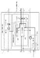
- the control path element 2000 includes a circuit AND101 that performs a logical product of the return value ret of the function processing unit 4000 and the true / false value of the immediately preceding element, and a register 103 that stores the result of the AND101.
- the data path element 3000 gives a required argument to the function processing unit 4000 among the previous calculation results and bypasses unnecessary arguments, and the output result of the function processing unit 4000.
- a register 102 for storing bypassed data.
- the return value ret of the function indicates whether the input data included in the event is predetermined data for identifying the event as a result of checking the input event 1000, that is, whether a certain event has occurred. Indicates a Boolean value.
- a result of a predetermined calculation using event information included in the event 1000 is referred to or stored.
- FIG. 3 is a diagram showing details of the function processing unit 4000 according to the present embodiment.
- the function processing unit 4000 includes a control comparison unit 4001 and a data calculation unit 4002.
- the control comparison unit 4001 outputs, as a return value ret, whether or not the event has occurred, from the result of the calculation performed by the data calculation unit 4002 or a calculated value during the calculation and the event 1000.
- the data calculation unit 4002 has the previous calculation result as an argument in, performs a predetermined calculation defined in the function based on the event 1000, and outputs the calculation result to the argument out. Note that at least the event 1000 may be input to the control comparison unit 4001.
- the data calculation unit 4002 may use only the event 1000 as an argument depending on the calculation defined in the function.
- regulated to a function is not specifically limited.
- the calculation may be a comparison with a predetermined character or character string.
- the calculation may be a process that performs no processing. In other words, the calculation may simply store the previous calculation result as an argument in or input data and output it as an argument out as it is.
- the regular expression for the character string described above has no argument that contributes to the calculation. Therefore, the character string collating process can be regarded as a function that simply compares whether or not a corresponding character is given internally and returns it as a return value.
- at least one function processed by the function processing unit 4000 is defined as a function having an argument. For this reason, in this embodiment, it is possible not only to detect an event string (including a single event) but also to define an operation to be performed on each event. Therefore, by combining the arithmetic devices, it is possible to configure an arithmetic device capable of detecting a complex event sequence and executing a predetermined operation on each event as necessary. The details will be described in the following embodiments.
- Embodiment 2 of the present invention Next, a second embodiment of the present invention will be described.
- a description will be given of an arithmetic device that performs an operation of a regular expression including an event sequence including events as an input and including one or more functions and operators.
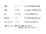
- FIG. 4 is a diagram for explaining an operator according to the present embodiment.
- the operator can be a concatenation that describes execution of the operation of the next function after one function, a sum that describes which operation result of the two functions is selected, or one time. There are repetitions that describe the continuous execution of the operations of the above functions.
- grouping is a notation provided for the purpose of solving the ambiguity of functions and operators. That is, when a function sequence is written as e1e2
- the function sequence means the former, the function sequence is described as e1 (e2
- the function sequence means the latter, the function sequence is described as (e1e2)
- the function sequence is expressed using a regular expression.
- Each function constituting the function sequence has an event as an input, that is, at least one function among the individual functions of the function sequence expressed by the regular expression has one or more arguments. Part or all of the input data included in the event is an argument of the function, but this is also an argument when the function refers to one or more calculation results in the preceding arithmetic unit. Then, the function outputs a true / false value indicating whether or not specific input data is detected as a return value.
- an event including a plurality of input data is input as an event string.
- the arithmetic device detects a specific event sequence from the input event sequence and outputs the calculation result at that time.
- the event means that it consists of data (event information) generated accompanying a certain event as described above.
- Specific examples of the event include, for example, the patient name, the name of the medicine, the amount of the medicine, the time for taking the medicine, the body temperature, etc. as the event information.
- the arithmetic device detects a case where a patient A has taken medicines B1, B2, and B3 in this order as an event sequence to be detected.
- the arithmetic device can output, for example, an average body temperature as a result of the operation defined by a function sequence including functions executed for individual events.
- the event column includes a column of event information, that is, continuous information. Therefore, a specific example of the event sequence includes real-time information input from, for example, a sensor or a terminal.
- the event is described as including a plurality of pieces of event information (input data), but the number of input data may be one.
- the arithmetic device 1 described in the first embodiment may be provided as many as the number of events to be detected.
- one arithmetic device is configured by a plurality of arithmetic devices, it is only necessary to include at least the arithmetic device 1 described in Embodiment 1, and other arithmetic devices may have different configurations. .
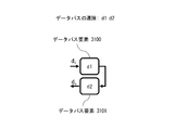
- FIG. 5A and FIG. 5B show concatenation in regular expressions of operations executed by the arithmetic device according to the present embodiment.
- the arithmetic device in this example may be configured using two arithmetic devices according to the first embodiment.
- the arithmetic device in this example includes two arithmetic devices having a control path element and a data path element, and at least one of the arithmetic devices according to the first embodiment may be used.
- FIG. 5A and 5B show connection methods for the control path and the data path.
- FIG. 5A shows a control path connection method.
- the control path element 2100 and the control path element 2101 are connected in series.
- FIG. 5B shows a data path connection method.
- the data path element 3100 and the data path element 3101 are connected in series.
- Each control path element and data path element may be composed of a function sequence as well as a function according to the regular expression rules shown in FIG.
- the data path element 3101 outputs the calculation processing result based on the calculation processing result of the data path element 3100
- the control path element 2101 outputs the detection result based on the result of the control path element 2100.
- FIGS. 6A and 6B show the sum in the regular expression of the operations executed by the arithmetic device according to the present embodiment.
- the arithmetic device in this example may also be configured using two arithmetic devices according to the first embodiment.
- the arithmetic device in this example includes two arithmetic devices having a control path element and a data path element, and at least one of the arithmetic devices according to the first embodiment may be used.
- FIG. 6A and 6B show connection methods for the control path and the data path.
- FIG. 6A shows a control path connection method.
- the output result c i of the immediately preceding control path is input to the control path element 2100 and the control path element 2101 in parallel.
- the outputs c 1 and c 2 of the control path element 2100 and the control path element 2101 are connected by a logical sum (OR) 202.
- the output C 0 of the OR 202 becomes the event detection result. That is, the OR 202 functions as a determination unit that determines that an event sequence has been detected when one or more of the control path element 2100 and the control path element 2101 detects an event.
- FIG. 6B shows a data path connection method.
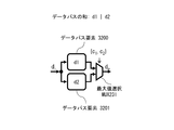
- output d i of the previous data path is input in parallel to a data path element 3200 and data path elements 3201.
- the result d 2 Results d 1 and data path elements 3201 of the data path element 3200 is connected to the multiplexer MUX201.
- the multiplexer MUX 201 outputs the result d 1 of the data path element 3200 if the output result c 1 of the control path 2200 is 1, and the result d 2 of the data path element 3201 if the output result c 2 of the control path 2201 is 1. Is output. That is, the output result d 0 of the multiplexer MUX 201 becomes the calculation result of the calculation corresponding to the event sequence.
- the multiplexer MUX 201 selects one of the operation results d 1 and d 2 of the data path element 3200 and the data path element 3201 according to the output results c 1 and c 2 of the control path element 2100 and the control path element 2101. Function as a first selection means for outputting.
- each control path element and data path element may be composed of not only a function but also a function sequence according to the regular expression rules shown in FIG.
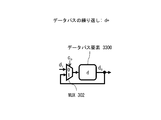
- FIG. 7A and FIG. 7B show repetition in the regular expression of the operation executed by the arithmetic device according to the present embodiment.
- the arithmetic device in this example may include one arithmetic device according to the first embodiment.
- FIG. 7 shows connection methods of the control path and the data path.
- FIG. 7A shows a control path connection method.
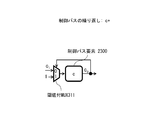
- a multiplexer MUX 301 is provided for inputting the result c i or 1 of the immediately preceding control path to the control path element 2300.
- Multiplexer MUX301 if the output result c 0 of the control path element 2300 is 0, the result c i of the previous control path, when the output result c 0 of the control path element 2300 is 1, 1 a control path elements 2300 To enter.
- the multiplexer MUX 301 serves as a second determination unit that determines whether or not to input the output c i of the previous control path element to the control path element 2300 according to the output result c 0 of the control path element 2300. Function.
- FIG. 7B shows a data path connection method.
- a multiplexer MUX 302 that inputs the result d i of the immediately preceding data path element or the output result d 0 of the data path element 3300 to the data path element 3300 is provided.
- the multiplexer MUX 302 outputs the result d i of the immediately preceding data path element when the output result c 0 of the control path element 2300 is 0 , and the data path element 3300 of the data path element 3300 when the output result c 0 of the control path element 2300 is 1.
- the output result d 0 is input to the data path element 3300.
- the multiplexer MUX 302 selects one of the output results d 0 and d i of the data path element 3300 and the preceding data path element as the data path element 3300 according to the output result c 0 of the control path element 2300. It functions as a third determination means for inputting.
- an event may be expressed using a structure including a plurality of pieces of event information (data).
- hardware such as an ASIC (Application Specific Integrated Circuit) or an FPGA (Field-Programmable Gate Array) is used in addition to a normal CPU (Central Processing Unit) for processing in real time. Therefore, it is important to replace event processing.
- ASIC Application Specific Integrated Circuit
- FPGA Field-Programmable Gate Array
- a function in which the arithmetic device performs an operation associated with a function having the input data included in the event as an argument and outputs a result, and outputs a comparison result of the input data as a return value A processing unit is provided. Therefore, an event sequence can be detected using the return value, and an operation defined corresponding to the event can be executed by the function processing unit. Therefore, the processing of the event sequence can be performed at high speed by executing the processing with the arithmetic unit configured by hardware.
- the present invention can be configured by software. Details will be described later. By realizing with software, it is not necessary to provide a dedicated circuit for event processing in the arithmetic unit. Therefore, the circuit scale of the arithmetic device can be reduced.
- Embodiment 3 of the present invention Next, a third embodiment of the present invention will be described.
- the arithmetic device in the present embodiment is obtained by connecting two arithmetic devices according to the first embodiment using the connection in the second embodiment.
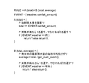
- FIG. 8 shows an example of regular expression concatenation in Embodiment 3 of the present invention.
- the regular expression is described as a concatenation of functions A and B having sum as an argument (see the “RULE” line). That is, the function A and the function B constitute a function sequence expressed by a regular expression.
- the event is composed of the sensor ID which is the event information and the temperature temp measured by the sensor.
- the function A outputs the temperature of the event information to the argument sum, and returns 1 if the sensor ID of the input event is 100, and 0 if it is different.
- the function B calculates the average value of the temperatures of the two events by calculating the sum of the value of the argument sum of the function A and the temperature of the input event and dividing by 2. If the input event ID is 200, 1 is returned, otherwise 0 is returned.
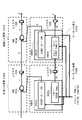
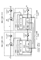
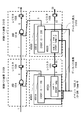
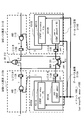
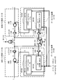
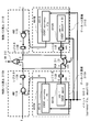
- FIG. 9 is a diagram illustrating an arithmetic device according to the present embodiment that performs arithmetic processing on the concatenation of the regular expressions shown in FIG.
- the computing device according to the present embodiment includes control path elements 2100A and 2101B and data path elements 3100A and 301B.
- the data path element 3100A includes a function processing unit 4000A and a register 102A
- the data path element 3101B includes a function processing unit 4000B and a register 102B.
- the control path element 2100A includes a logical product (AND) 101A and a register 103A
- the control path element 2101B includes an AND 10BA and a register 103V.
- the function processing unit 4000A includes a control comparison unit 4001A and a data calculation unit 4002A
- the function 4001B includes a control comparison unit 4001B and a data calculation unit 4002B.
- the control path element 2100A and the control path element 2101B, and the data path elements 3100A and 3101B are connected as a connection in accordance with the rules of FIG. 2, FIG. 3, and FIG.
- control comparison unit 4001A of the function processing unit 4000A determines whether or not the ID of the input event matches 100, and outputs a return value ret.
- the data calculation unit 4002A stores the temperature temp of the input event in the output argument sum.
- the control comparison unit 4001B of the function processing unit 4000B determines whether or not the ID of the input event matches 200, and outputs a return value ret.
- the data calculation unit 4002B takes the average of the temperature temp of the input event and the temperature of the function A, specifically, the value stored in the register 102A of the data path element 3100A.
- the input of the control path element 2100A is fixed to 1 because there is no previous result, and the data path element 3100A does not require an input from the previous stage, so no value is given. .
- FIG. 10 is a diagram illustrating an example of the operation of the arithmetic device according to the present embodiment that performs the concatenation operation in the regular expression illustrated in FIG. 9.
- FIG. 10 shows an example in which an event 1000_1 having an ID of 100 and a temperature of 50 is given to the function processing units 4000A and 4000B as inputs.
- the output result of the control comparison unit 4001A is 1, the output result of the data calculation unit 4002A is 50, the output result of the AND101A is 1, the output result of the control comparison unit 4001B is 0, the output result of the AND101B is 0, and the data calculation unit The output result of 4002B is 25.
- FIG. 11 is a diagram illustrating an example of the operation of the arithmetic device illustrated in FIG. 9.
- FIG. 11 shows an example in which event 1000_2 having an ID of 200 and a temperature of 150 is given to the function processing units 4000A and 4000B after the event 1000_1 input shown in FIG.
- the output result of the control comparison unit 4001A is 0, the output result of the data calculation unit 4002A is 150, the output result of the logical AND 101A is 0, the output result of the control comparison unit 4001B is 1, and the output result of the logical AND 101B is 1
- the output result of the data calculation unit 4002B is 100.
- FIG. 12 is a diagram illustrating an example of the operation of the arithmetic device illustrated in FIG. 9.
- FIG. 12 shows an example in which an event 1000_3 having an ID of 300 and a temperature of 0 is given to the function processing units 4000A and 4000B after the input of the event 1000_2 shown in FIG.
- the output result of the control comparison unit 4001A is 0, the output result of the data calculation unit 4002A is 0, the output result of the AND101A is 0, the output result of the control comparison unit 4001B is 0, the output result of the AND101B is 0, and the data calculation unit
- the output result of 4002B is 75.
- the event detection result output from the register 103B of the control path element 2101B is 1, and the operation result of the function A (sum) B (sum) output from the register 102 of the data path element 3101B is 100. That is, since the output of the register 103B is 1, it can be seen that a match has occurred in this event sequence, that is, that the target event sequence has been detected, and the average temperature value (calculation result) at that time is From the output result of the register 102B, it can be seen as 100.
- FIG. 13 is a diagram illustrating an example of the connection operation of the arithmetic device illustrated in FIG. 9.
- FIG. 13 shows an example in which an event 1000_4 having an ID of 300 and a temperature of 0 is given to the function processing units 4000A and 4000B after the input of the event 1000_1 shown in FIG.
- the output result of the control comparison unit 4001A is 0, the output result of the data calculation unit 4002A is 0, the output result of the AND101A is 0, the output result of the control comparison unit 4001B is 0, the output result of the AND101B is 0, and the data calculation unit
- the output result of 4002B is 25.
- the output of the register 103B becomes 0 and the event sequence is not detected.
- the output result of the data calculation unit 4002B is treated as invalid data and is not adopted as a normal output result of the present arithmetic unit.
- the arithmetic device thus performs an operation on the regular expression described by the functions A (sum) B (sum), and generates an event sequence that matches the comparison result defined in the function. It is possible to detect and output the calculation result at that time.
- the control path element 2100A and the control path element 2101B, and the data path elements 3100A and 3101B are connected in a connected manner in accordance with the rules of FIGS. With this configuration, it is possible to perform a regular expression described by a function A (sum) B (sum).
- each data path element 3100A and 3101B has the control comparison units 4001A and 4001B, it is possible to detect an event sequence that matches the comparison result defined in the function. Further, since the data calculation units 4002A and 4002B are provided, the calculation defined in each function can be executed and the calculation result can be output.
- Embodiment 4 of the present invention a fourth embodiment of the present invention will be described.
- the arithmetic device in the present embodiment is obtained by connecting two arithmetic devices according to the first embodiment using the sum in the second embodiment.
- FIG. 14 is a diagram showing an example of the sum in the regular expression shown in the fourth embodiment of the present invention.
- the regular expression is described as the sum of functions A and B having “en” as an argument (see the “RULE” line).
- the event includes, as event information, a currency name “currency” and a currency amount “Amount”.
- the function A outputs the currency amount in the event information to the argument yen, and returns 1 if the name of the currency of the input event is Yen, and 0 if it is different.
- the function B outputs a value obtained by multiplying the currency amount of the input event by 80 to the argument yen, and returns 1 if the name of the passage of the input event is dollars, and 0 if different. That is, in this example, an example is shown in which the currency is unified into yen.
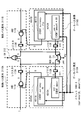
- FIG. 15 is a diagram showing an arithmetic device according to the present embodiment that performs the arithmetic operation of the sum in the regular expression shown in FIG.
- the arithmetic device according to the present embodiment includes a control path element 2110 ⁇ / b> A and a control path element 2111 ⁇ / b> B via a logical sum (OR) 212.
- Data path elements 3110A and 3111B are connected via a multiplexer MUX211.
- the data path element 3110A includes a function 4010A and a register 112A
- the data path element 3111B includes a function 4010B and a register 112B
- the control path element 2110A includes an AND 111A and a register 113A
- the control path element 2111B includes an AND 111B and a register 113B
- the function 4010A includes a control comparison unit 4011A and a data calculation unit 4012A
- the function 4010B includes a control comparison unit 4011B and a data calculation unit 4012B.
- control comparison unit 4011A of the function 4010A detects whether the name of the currency of the input event matches the yen, and outputs a return value ret.
- the data calculation unit 4012A stores the currency amount “amount” of the input event in the output argument “en”.
- control comparison unit 4011B of the function 4010B detects whether or not the name of the currency of the input event matches the dollar, and outputs a return value ret.
- the data calculation unit 4012B multiplies the currency amount “amount” of the input event by 80 and outputs it as yen. Note that the input of the control path elements 2110A and 2111B is fixed to 1 because there is no previous result, and the data path elements 3110A and 3111B do not require input from the previous stage, so no value is given.
- FIG. 16 is a diagram illustrating an example of the operation of the arithmetic device that performs the arithmetic operation of the sum in the regular expression illustrated in FIG. 15.
- FIG. 16 shows an example in which an event 1010_1 having a currency name of yen and a passing amount of 100 as an input is given to the functions 4010A and 4010B.
- the output result of the control comparison unit 4011A is 1, the output result of the data calculation unit 4012A is 100, the output result of the AND 111A is 1, the output result of the control comparison unit 4011B is 0, the output result of the AND 111B is 0, and the data calculation unit
- the output result of 4012B is 8000.
- FIG. 17 is a diagram illustrating an example of the operation of the arithmetic device that performs the arithmetic operation of the sum in the regular expression illustrated in FIG. 15.
- FIG. 17 shows an example in which an event 1010_2 with the currency name as the input and a passing amount of 5 is given to the functions 4010A and 4010B as input after the input of the event 1010_1 shown in FIG.
- the output result of the control comparison unit 4011A is 0, the output result of the data calculation unit 4012A is 5, the output result of the AND111A is 0, the output result of the control comparison unit 4011B is 0, the output result of the AND111B is 0, and the data calculation unit The output result of 4012B is 400.
- the output of the OR 212 that outputs the event detection result is 1, it is understood that a match has occurred in the input event sequence, that is, an event has been detected.
- the calculation result in the regular expression at that time that is, the yen-denominated currency amount is known as 100 from the output result of the multiplexer MUX 211.
- FIG. 18 is a diagram illustrating an example of the operation of the arithmetic device that performs the arithmetic operation of the sum in the regular expression illustrated in FIG. 15.
- FIG. 18 shows an example in which an event 1010_3 with a currency name of dollars and a passing amount of 10 is given to the functions 4010A and 4010B as input.
- the output result of the control comparison unit 4011A is 0, the output result of the data calculation unit 4012A is 10, the output result of the AND 111A is 0, the output result of the control comparison unit 4011B is 1, the output result of the AND 111B is 1, and the data calculation unit The output result of 4012B is 800.
- FIG. 19 is a diagram illustrating an example of the operation of the arithmetic device that performs the arithmetic operation of the sum in the regular expression illustrated in FIG. 15.
- FIG. 19 shows an example in which the event 1010_3 shown in FIG. 18 continues to be input, and the event 1010_4 with the currency name as the input and the passing amount 5 is given to the functions 4010A and 4010B as input.
- the output result of the control comparison unit 4011A is 0, the output result of the data calculation unit 4012A is 5, the output result of the AND111A is 0, the output result of the control comparison unit 4011B is 0, the output result of the AND111B is 0, and the data calculation unit The output result of 4012B is 0.
- the output of the OR 212 indicating the event detection result is 1, it can be seen that a match has occurred in the input event sequence, and the yen-denominated currency amount that is the calculation result at that time is determined by the multiplexer MUX 211. It can be seen as 800 from the output result.
- FIG. 20 is a diagram illustrating an example of the operation of the arithmetic device that performs the arithmetic operation of the sum in the regular expression shown in FIG.
- an event 1010_5 with the currency name as the input and a passing amount of 5 is given to the functions 4010A and 4010B as input.
- the output result of the control comparison unit 4011A is 0, the output result of the data calculation unit 4012A is 5, the output result of the AND111A is 0, the output result of the control comparison unit 4011B is 0, the output result of the AND111B is 0, and the data calculation unit The output result of 4012B is 400.
- the output of the OR 212 as the detection result is 0, and the event string is not detected.
- the output results of the data calculation units 4012A and 4012B are both treated as invalid data, and are not adopted as regular output results of the present computing device.
- control path element 2110A and the control path element 2111B and the data path elements 3110A and 3111B are connected as a sum in accordance with the rules of FIGS. With this configuration, it is possible to perform a regular expression described by the function A (sum)
- each data path element 3110A and 3111B includes the control comparison units 4011A and 4011B, it is possible to detect an event sequence that matches the comparison result defined in the function. Further, since the data calculation units 4012A and 4012B are provided, the calculation defined in each function can be executed and the calculation result can be output.
- Embodiment 5 of the present invention a fifth embodiment of the present invention will be described.
- the arithmetic device according to the present embodiment has two arithmetic devices according to the first embodiment and is connected using the sum described in the second embodiment.
- FIG. 21 shows an example of repetition in the regular expression shown in the fifth embodiment of the present invention.
- a function that repeats a function A having a total total of precipitation per second as an argument and a total total of precipitation per second as an input and calculates an average per second of accumulated precipitation in rainy weather. It is described as a concatenation with B (see the “RULE” line).
- the event includes, as event information, a weather situation weather and a precipitation amount perinmount_second per second. Note that events are sent every second.
- function A sums and outputs the precipitation per second of the event information to total, and returns 1 if the weather condition of the input event is rain, and returns 0 if it is different.
- the function B receives the sum of precipitation per second of the function A as an input, and outputs an average value based on the number of events (accumulated seconds) so far by a built-in function called get_num_event, and if the weather condition of the input event is sunny Returns 1 or 0 if different. That is, in this example, the precipitation per second in the rainy weather until it clears is integrated and the average is output.
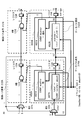
- FIG. 22 is a diagram showing the arithmetic device according to the present embodiment that performs the repeated arithmetic operation in the regular expression shown in FIG.
- the arithmetic device according to the present embodiment includes a control path element 2120A, a control path element 2121B, and data path elements 3120A and 3121B. Are connected as repetitions in the second embodiment described above.
- the data path element 3120A includes a function 4020A and a register 122A
- the data path element 3121B includes a function 4020B and a register 122B
- the control path element 2120A includes an AND 121A and a register 123A
- the control path element 2121B includes an AND 121B and a register 123B
- the function 4020A includes a control comparison unit 4021A and a data calculation unit 4022A
- the function 4020B includes a control comparison unit 4021B and a data calculation unit 4022B.
- control comparison unit 4021A of the function 4020A determines whether or not the weather condition of the input event matches rain, and outputs a return value ret.
- the data calculation unit 4022A accumulates precipitation per second of the input event.
- control comparison unit 4021B of the function 4020B determines whether or not the weather condition of the input event matches sunny, and outputs a return value ret.
- the data calculation unit 4022B outputs the average precipitation per second during rainy weather, which is obtained by dividing the cumulative precipitation per second output of the function A by the total number of seconds. Note that the previous value input to the multiplexer MUX 321A is fixed to 1 because there is no previous result, and the previous value input to the multiplexer MUX 322A is fixed to 0 for integration.
- FIG. 23 is a diagram illustrating an example of the operation of the arithmetic device according to the present embodiment that performs the repeated arithmetic processing in the regular expression shown in FIG.
- FIG. 23 shows an example in which an event 1020_1 having a rainy weather condition and precipitation per second of 10 is given to functions 4020A and 4020B as inputs.
- the output result of the control comparator 4021A is 1, the input of the data calculator 4022A is 0, the output result of the data calculator 4022A is 10, the output result of the AND121A is 1, the output result of the control comparator 4021B is 0, and AND121B. Is 0, and the output result of the data calculation unit 4022B is 0.
- FIG. 24 is a diagram illustrating an example of the operation of the arithmetic device according to the present embodiment that performs the repeated arithmetic processing in the regular expression shown in FIG.
- FIG. 24 shows an example in which an event 1020_2 having a weather condition of rain and a precipitation amount of 20 per second is given to the functions 4020A and 4020B as an input following the event 1020_1 shown in FIG.
- the output result of the control comparison unit 4021A is 1, the input of the data calculation unit 4022A is 10, the output result of the data calculation unit 4022A is 30, the output result of AND121A is 1, the output result of the control comparison unit 4021B is 0, and AND121B.
- the output result is 0, and the output result of the data calculation unit 4012B is 30 because the accumulated number of seconds is 1.
- FIG. 25 is a diagram illustrating an example of the operation of the arithmetic device according to the present embodiment that performs the repeated arithmetic processing in the regular expression shown in FIG.
- an event with clear weather conditions and 0 precipitation per second is given to the functions 4020A and 4020B as input.
- the output result of the control comparison unit 4021A is 0, the input of the data calculation unit 4022A is 30, the output result of the data calculation unit 4022A is 30, the output result of the AND121A is 0, the output result of the control comparison unit 4021B is 1, and the AND121B The output result of 1 is 1, and the output result of the data calculation unit 4012B is 15 because the accumulated number of seconds is 2.
- FIG. 26 is a diagram illustrating an example of the operation of the arithmetic device according to the present embodiment that performs the repeated arithmetic processing in the regular expression shown in FIG.
- FIG. 26 shows an example in which an event 1020_4 having a cloudy weather condition and 0 precipitation per second is given to the functions 4020A and 4020B following the input of the event 1020_3 shown in FIG.
- the output result of the control comparison unit 4021A is 0, the input of the data calculation unit 4022A is 0, the output result of the data calculation unit 4022A is 0, the output result of the AND121A is 0, the output result of the control comparison unit 4021B is 0, and AND121B.
- the output result is 0, and the output result of the data calculation unit 4022B is 10 because the accumulated number of seconds is 1.
- the output of the register 123B indicating the event detection result is 1, it can be seen that a match has occurred in this event sequence, that is, that an event has been detected. At that time, the average accumulated precipitation per second is the output result of the register 122B. It turns out that it is 15.
- FIG. 27 is a diagram illustrating an example of the operation of the arithmetic device according to the present embodiment that performs the repeated arithmetic processing in the regular expression shown in FIG.
- FIG. 27 shows an example in which an event 1010_5 in which the weather condition is cloudy and the precipitation amount per second is 0 is given to the functions 4020A and 4020B following the input of the event 1020_1 shown in FIG.
- the output result of the control comparison unit 4021A is 0, the input of the data calculation unit 4022A is 30, the output result of the data calculation unit 4022A is 30, the output result of the AND121A is 0, the output result of the control comparison unit 4021B is 0, and AND121B.
- the output result is 0, and the output result of the data calculation unit 4022B is 15 because the accumulated number of seconds is 2.
- the output of the register 123B indicating the event detection result is 0, and the event string is not detected.
- the output result of the data calculation unit 4022B is treated as invalid data and is not adopted as a normal output result of the present arithmetic unit.
- the repetition of the control path element 2120A and the control path element 2121B are connected in accordance with the rules of FIGS. 2, 3, 5, and 7, and the repetition of the data path element 3120A is performed. And the data path element 3121B are connected as a connection.
- each data path element 3120A and 3121B includes the control comparison units 4021A and 4021B, it is possible to detect an event sequence that matches the comparison result defined in the function.
- the data calculation units 4022A and 4022B are provided, the calculation defined in each function can be executed and the calculation result can be output.
- Embodiment 6 of the present invention is 1-bit information representing a true / false value.
- the return value of the function may be extended to multiple bits.
- an example is shown in which the return value of the function implemented by the arithmetic unit is a plurality of bits.
- the return value may mean the probability of event occurrence. That is, the return value of the function does not indicate whether an event has occurred, but indicates the event occurrence probability.
- the occurrence probability of an event can be interpreted as the possibility that the event has occurred.
- the occurrence probability of an event sequence can also be defined.
- the return value indicating the event occurrence probability can be obtained as follows. If the data included in the event (event information) is a value that follows physical fluctuations, for example, if it represents the temperature at the heat source, the probability of occurrence of that temperature is calculated according to the probability distribution calculated in advance from the physical laws related to the heat source. Can be sought. In addition, when the event information is data that does not follow such physical laws, for example, in terms of testing, a well-known distribution such as logistics distribution or normal distribution is assumed, and the probability of occurrence from that distribution is assumed. Can be calculated. Furthermore, the current event occurrence probability may be calculated according to the data frequency that occurred in the past event sequence. In addition, any method may be used for calculating the event occurrence probability as long as it is a method used in the field of statistical calculation / data mining, such as Bayesian method or maximum likelihood method.
- the return value is a plurality of bits
- a logical operation between the return values cannot be defined.
- a specific example of the calculation method of the return values of a plurality of bits is shown below.
- FIG. 28 is a diagram illustrating an arithmetic device according to the present embodiment that executes a function when the return value of the function is a plurality of bits.
- the plurality of bits represent the occurrence probability of the event of this function.
- the occurrence probability of an event is defined as a return value, unlike FIG. 2, instead of the logical sum AND 101 of the result c i of the preceding control path element and the result from the function calculation unit 4200, as shown in FIG.
- a multiplier 110 is provided.
- the register 103 outputs the occurrence probability c 0 of the event sequence itself.
- the return value ret of the function is not limited to the occurrence probability of the event, but may represent other states. In that case, you may provide a different computing unit instead of a multiplier.
- FIG. 29A and FIG. 29B are diagrams illustrating connection of control path elements and data path elements when performing a sum operation on a function having a return value of multiple bits. Unlike FIG. 6A and FIG. 6B, the logical sum 202 of the results of the control path element 2200 and the control path element 2201 is not performed. As shown in FIG. 29A, whichever of the control path element 2200 and the control path element 2201 A maximum value selection calculation unit 232 that selects and outputs the larger value is provided. This means that a function that outputs a larger event occurrence probability is selected.
- the configuration with the output d 2 output d 1 and the data path elements 3201 of the data path element 3200 is selected by the output magnitude of c 1, c 2 of the control path elements 2200,2201 ( Figure 29B). That is, the output d 1 is selected by the maximum value selection MUX 231 when the output result c 1 is large, and the output d 2 is output as the output d 0 when the output result c 2 is large.
- the selection conditions in the maximum value selection calculation unit 232 and the maximum value selection MUX 231 are examples, and a function or an output result may be selected based on a condition determination other than the above.
- FIG. 30A and FIG. 30B are diagrams for explaining connection of control path elements and data path elements when iterative calculation is performed on a function having a return value of a plurality of bits.
- the input of the control path element 2300 and the input of the data path element 3300 do not use MUX, but selects an input based on whether or not an event occurrence probability exceeds a certain threshold value.
- MUXs 311 and 312 with thresholds are provided.
- the results c i and d of the control path elements and data path elements from the previous stage will be used. i is selected and input. That is, even if the occurrence probability of a single event is 80%, for example, if it is repeated 10 times, the probability is 10%.
- Embodiment 7 of the present invention handles an operation stop request input from the arithmetic device located in the subsequent stage, and corresponds to the difference in the number of function arithmetic cycles in each arithmetic device.
- FIG. 31 is a diagram showing a configuration of the arithmetic device according to the present embodiment.
- processing units having the same name and the same reference numerals, which are not described below, basically perform the same processing as in the first and second embodiments.
- the computing device 1 has a control path element 2000 and a data path element 3000, similarly to the configuration shown in FIG.
- the data path element 3000 includes a function processing unit 4000, and the function processing unit 4000 includes a control comparison unit 4001 and a data calculation unit 4002.
- the arithmetic unit 1 has a register 104 in the data path element 3000 in addition to the configuration of FIG.
- the arithmetic device 1 further includes a logical product AND 105 and a queue 106.
- the control path element 2000 receives the output result c i of the immediately preceding control path.
- the function processor 4000 in addition to the output d i of the previous data path, effectiveness information indicating the effectiveness of the output result of a previous data path (hereinafter, the validity information takes a value of 0 or 1 shall be entered in a digital signal format to as Valid signal.)
- v i is inputted.
- the valid signal v i indicates invalidity when 0 and indicates validity when it is 1.
- an operation stop request r i (hereinafter, the request is input in the form of a digital signal having a value of 0 or 1) output from the arithmetic unit located in the subsequent stage to the AND AND 105. Is entered).
- the Ready signal r i is a signal indicating whether or not the arithmetic unit located in the subsequent stage requests the operation stop. When the signal is 1, it indicates that the operation stop is not requested, and when it is 0, the operation stop is requested. Indicates.
- the arithmetic device 1 can stop the processing of the data calculation unit 4002. For example, a later-stage arithmetic device having a low processing speed outputs a Ready signal r i having a value of 0 to the preceding arithmetic device during execution of the arithmetic processing. At this time, the arithmetic unit 1 may stop the processing of the data calculation unit 4002.
- the arithmetic unit 1 waits for the arithmetic processing of the latter stage of the arithmetic unit is complete Ready signal r i is 1, may be resume processing data calculating unit 4002. Note that when the processing of the data calculation unit 4002 is not completed, the arithmetic unit 1 does not need to immediately stop the processing of the data calculation unit 4002 even if the Ready signal r i is 0. As described above, the arithmetic device 1 can perform control of stop / permission of processing of the data calculation unit 4002 according to the value of the Ready signal r i .
- An event 1000 is input to the queue 106.
- the queue 106 functions as a holding unit that sequentially holds the events 1000.
- the Valid signal v i is also input to the queue 106.
- Queue 106 the value of the input Valid signal v i is the case of 1 (valid), for inputting an event at the head in the data calculation unit 4002. Further, the queue 106 inputs an empty signal (1: holding an event, 0: not holding an event), which is information indicating whether an event is held (event holding information), to the logical product AND 105. To do.
- the logical product AND 105 When either the empty signal or the Ready signal r i is 0, the logical product AND 105 inputs the Ready signal r 0 having a value of 0 to the preceding arithmetic unit. That is, the logical product AND 105 operates as an operation stop request generating unit that generates a Ready signal to be input to the preceding arithmetic unit.
- the data calculation unit 4002 When either the empty signal or the ready signal r i is 0, the data calculation unit 4002 is in a state where the operation cannot be executed. (For both the empty signal and the Ready signal r i 1) Otherwise, the data calculation unit 4002 is executed a state capable of operation. At this time, the logical product AND 105 transmits an execution availability state indicating whether or not the data calculation unit 4002 can execute the operation to the preceding arithmetic unit.
- the arithmetic device 1 can grasp the processing status of the arithmetic device located in the subsequent stage from the Ready signal.
- the calculation device in the previous step The calculation result can be reliably transmitted to the apparatus. Therefore, the calculation can be performed normally.
- the configuration in FIG. 31 is a configuration that assumes that the propagation of the Ready signal to the previous stage is completed in one cycle.
- a prediction mechanism is provided for predicting that the queue 106 will be empty or that the arithmetic processing of the subsequent arithmetic unit will be delayed. Just do it.
- the Ready signal can be accurately propagated by setting the value of the Ready signal according to the prediction by the prediction mechanism.
- the prediction mechanism knows that the clock becomes empty after several clocks from the configuration of its own queue 106, or how many clocks are necessary for the arithmetic processing of the post-stage arithmetic unit, so what is the ready signal reception from the post-stage? If the clock is expected to be delayed, the Ready signal is set to 0 first.
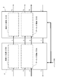
- FIG. 32 shows a diagram in which regular expression concatenations are constructed using the two arithmetic units shown in FIG.
- the first arithmetic unit A has a control path element 2130A and a data path element 3130A.
- the second arithmetic unit B has a control path element 2131B and a data path element 3131B. According to the rules of FIGS. 2, 3, and 5, the control path element 2130A and the control path element 2131B, and the data path element 3130A and the data path element 3131B are connected as a connection.
- the valid signal v i is input to the data path element 3130A, and the data path element 3130A inputs the valid signal v to the data path element 3131B according to the calculation result.
- Data path element 3131B inputs the Valid signal v 0 to the subsequent computing device.
- the ready signal r i is input to the second arithmetic unit B, and the second arithmetic unit B inputs the ready signal r to the first arithmetic unit A.
- the configuration of the arithmetic unit shown in FIG. 32 is such that the control path element 2130A and the control path element 2131B, and the data path element 3130A and the data path element 3131B are connected as a connection in accordance with the rules of FIG. 2, FIG. 3, and FIG. ing.
- regular expressions described by concatenation can be calculated.
- FIG. 33 shows a diagram in which the sum of regular expressions is constructed using the two arithmetic devices shown in FIG.
- the first arithmetic unit A has a control path element 2140A and a data path element 3140A.
- the second arithmetic unit B has a control path element 2141B and a data path element 3141B.
- the control path element 2140A and the control path element 2141B, and the data path element 3140A and the data path element 3141B are connected as a sum.
- the Valid signal v i and the Ready signal r i are input to the first arithmetic device A and the second arithmetic device B.
- the first arithmetic unit A is connected to the shifter 204.
- the second arithmetic unit B is connected to the shifter 205.
- the shifter 204 receives the control path output result c 1 of the control path element 2140A, the data path output result d 1 of the data path element 3140A, and the Valid signal v 1 of the data path element 3140A.
- the shifter 205 receives the control path output result c 2 of the control path element 2141B, the output result d 2 of the data path of the data path element 3141B, and the Valid signal v 2 of the data path element 3141B.
- the shifter 204 and the shifter 205 operate as delay means for providing a delay in order to eliminate the difference in the number of operation cycles between the first arithmetic device A and the second arithmetic device B. For example, when the arithmetic cycle of the first arithmetic unit A is three cycles less than the arithmetic cycle of the second arithmetic unit B, the shifter 204 gives a delay of three cycles to each signal. Note that the shifters 204 and 205 need not be provided when the arithmetic cycle of the first arithmetic unit A and the arithmetic cycle of the second arithmetic unit B are the same.
- the AND signal 203 receives the Valid signal v 1 of the data path element 3140A and the Valid signal v 2 of the data path element 3141B.
- the logical product AND 203 inputs 1 as a Valid signal to a subsequent arithmetic unit only when both (Valid signal v 1 and Valid signal v 2 ) are 1.
- the logical product AND206, Ready signal r 1 from the first arithmetic unit A, the Ready signal r 2 from the second arithmetic unit B is input.
- the logical product AND 203 inputs a Ready signal having a value of 0 to the arithmetic unit located in the preceding stage when either of the Ready signals is 0.
- control path element 2140A and the control path element 2141B, and the data path element 3140A and the data path element 3141B are connected as a sum in accordance with the rules of FIG. 2, FIG. 3, and FIG. ing.
- this configuration it is possible to perform a regular expression described by a sum.
- FIG. 34 shows a diagram in which repetition of regular expressions is configured using the arithmetic unit shown in FIG.
- the arithmetic device has a control path element 2150A and a data path element 3150A.
- the iterative logic 400 is a processing unit including the above-described multiplexer MUX 301 and the like, and performs processing for controlling repetition in a regular expression.
- the iterative logic 400 selects the outputs c i , d i , and v i of the arithmetic unit located in the previous stage, and the control path Input to the element 2150A and the data path element 3150A.
- the iterative logic 400 is the output of the control path element 2150A, c 0 , the output of the data path element 3150A, d 0 , and v 0 is selected, the control path element 2150A, and inputs the data path elements 3150a.
- the iterative logic 400 controls the Ready signal r 0 supplied to the preceding arithmetic unit to be 0 during the arithmetic processing by the data path element 3150A. Note that the iterative logic 400 controls the Ready signal r 0 to be supplied to the preceding-stage arithmetic unit to 0 even when the Ready signal r i having a value of 0 is input from the subsequent-stage arithmetic unit.
- the iterative logic 400 may be provided inside the arithmetic device or may be provided outside the arithmetic device.
- Embodiment 8 of the present invention will be described.
- the arithmetic device is basically assumed to be hardware.
- the computer is a program for causing a computer to execute arithmetic processing that receives an event including one or more input data as input. It is also possible.
- the program according to the present embodiment performs the processing specified in the function having the input data as an argument, outputs the result, and outputs the comparison result of the input data as the return value to the function processing unit.
- Data processing to be performed, and control processing to detect an event using the return value of the function are examples of the program according to the present embodiment.
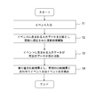
- FIG. 35 is an example of a flowchart showing the operation of the program according to the present embodiment.
- the program uses the input data included in the event as an argument, and performs a calculation process defined in the function (step S2). On the other hand, it is compared whether or not the input data included in the event is predetermined data (step S3).
- steps S2 and S3 are data processes executed by the function processing unit in the first to seventh embodiments.
- the return value in step S3 is used as a comparison result indicating whether or not the input event is a detection target event, and if necessary, a predetermined event or event sequence is generated together with the comparison result in the previous stage. Is detected (step S4).
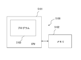
- FIG. 36 is a diagram illustrating a configuration example of an apparatus that executes a program according to the present embodiment.
- a computer 5100 has a CPU 5101 (Central Processing Unit) and a memory 5102 composed of ROM (Read Only Memory) or RAM 5103 (Random Access Memory).
- ROM Read Only Memory
- RAM 5103 Random Access Memory
- an OS Operating System
- an OS for operating the computer may be provided in the computer that constructs the information processing apparatus.
- the CPU 5101 loads various programs 5103 stored in the memory 5102 and executes various processes according to the programs 5103. In the present embodiment, for example, the above-described data processing and control processing are executed.
- the memory 5102 also stores data necessary for the CPU 5101 to execute various processes as appropriate.
- Non-transitory computer readable media include various types of tangible storage media (tangible storage medium).
- Examples of non-transitory computer readable media are magnetic recording media (eg flexible disks, magnetic tapes, hard disk drives), magneto-optical recording media (eg magneto-optical disks), CD-ROM, CD-R, CD-R / W Semiconductor memory (for example, mask ROM, PROM (Programmable ROM), EPROM (Erasable ROM), flash ROM, RAM).
- the program may also be supplied to the computer by various types of temporary computer-readable media. Examples of transitory computer readable media include electrical signals, optical signals, and electromagnetic waves.
- the temporary computer-readable medium can supply the program to the computer via a wired communication path such as an electric wire and an optical fiber, or a wireless communication path.
- the program according to the present embodiment processes all the arithmetic processes by software.
- the arithmetic processing of the present invention can be processed by software without using an arithmetic device as hardware.
Landscapes
- Engineering & Computer Science (AREA)
- Theoretical Computer Science (AREA)
- Physics & Mathematics (AREA)
- General Engineering & Computer Science (AREA)
- General Physics & Mathematics (AREA)
- Databases & Information Systems (AREA)
- Software Systems (AREA)
- Computational Linguistics (AREA)
- Data Mining & Analysis (AREA)
- Multimedia (AREA)
- Information Retrieval, Db Structures And Fs Structures Therefor (AREA)
Abstract
Description
1)イベント列を検出できること
2)イベント列に付随したデータに対して演算が実行できること
を満足することができず、結果、システマティックにイベント処理の回路を構成することはできない。
本実施の形態にかかる演算装置は、1以上のデータ(以下、入力データという。)を含むデータ群(イベント)を入力とし、所定の演算を実行するものである。具体的には、イベントを入力とし、入力データを引数とする関数において規定された演算を実行し結果を出力すると共に、入力データの比較結果を戻り値として出力し、また、関数の戻り値を使用してイベントを検出する処理を実行する。
また、関数に規定される演算の内容は特に限定されない。例えば、演算は、所定の文字又は文字列との比較であってもよい。さらに、演算は、何も処理をしないものであってもよい。すなわち、演算は、直前の計算結果を引数in、または入力データを単に格納し、そのまま引数outとして出力するものであってもよい。
これに対し、本実施の形態においては、関数処理部4000にて処理される、少なくとも1つの関数は、引数を有する関数として定義される。このため、本実施の形態においては、イベント列(単独のイベントも含む。)を検出するのみではなく、個々のイベントに対して実行すべき演算を定義することができる。
従って、この演算装置を組み合わせることによって、複雑なイベント列を検出し、必要に応じて個々のイベントに所定の演算を実行することができる演算装置を構成することができる。以下の実施の形態においてその詳細を説明する。
次に、本発明の実施の形態2について説明する。本実施の形態においては、イベントからなるイベント列を入力とし、1以上の関数と演算子とを含む正規表現の演算を実施する演算装置について説明する。
図5A及び図5Bは、本実施の形態における演算装置によって実行される演算の、正規表現における連接を示す。本例における演算装置は、実施の形態1にかかる演算装置を2つ用いて構成されてもよい。あるいは、本例における演算装置は、制御パス要素及びデータパス要素を有する2つの演算装置からなり、少なくとも一方が実施の形態1にかかる演算装置であってもよい。
図6A及び図6Bは、本実施の形態における演算装置によって実行される演算の、正規表現における和を示す。本例における演算装置も、実施の形態1にかかる演算装置を2つ用いて構成されてもよい。あるいは、本例における演算装置は、制御パス要素及びデータパス要素を有する2つの演算装置からなり、少なくとも一方が実施の形態1にかかる演算装置であってもよい。
図7A及び図7Bは、本実施の形態における演算装置によって実行される演算の、正規表現における繰り返しを示す。本例における演算装置は、実施の形態1にかかる演算装置1つを構成に含んでもよい。
1)イベントがどのような順序で発生したかを検出すること(例:イベントAの後にイベントBがきて、最後にイベントCがくる)
2)所定の条件にマッチした各イベントに対して、定義された計算ができること(例:イベントAで渡された温度とイベントBで渡された温度の平均をとる)
の両者を満足することが重要である。
なお、一方で、本願発明は、ソフトウェアで構成することも可能である。詳細は、後述する。ソフトウェアで実現することによって、演算装置にイベント処理用の専用回路を備える必要がなくなる。従って、演算装置の回路規模を削減することができる。
次に、本発明の実施の形態3について説明する。本実施の形態における演算装置は、実施の形態1にかかる演算装置2つを上述の実施の形態2における連接を用いて接続したものである。
そして、図2、図3、及び図5の規則に従い、制御パス要素2100Aと制御パス要素2101B、データパス要素3100Aと3101Bとが、それぞれ連接として接続されている。
次に、本実施の形態にかかる演算装置のイベント列の処理方法について説明する。図10は、図9で示した正規表現における連接の演算を実施する本実施の形態にかかる演算装置の動作の一例を示す図である。図10において、入力としてIDが100、温度が50のイベント1000_1が関数処理部4000A及び4000Bに与えられる例を示している。この結果、制御比較部4001Aの出力結果は1、データ計算部4002Aの出力結果は50、AND101Aの出力結果は1、制御比較部4001Bの出力結果は0、AND101Bの出力結果は0、データ計算部4002Bの出力結果は25となる。
図11は、図9で示した演算装置の動作の一例を示す図である。図11は、図10に示すイベント1000_1入力の後に、入力としてIDが200、温度が150のイベント1000_2が関数処理部4000A及び4000Bに与えられた例を示している。この結果、制御比較部4001Aの出力結果は0、データ計算部4002Aの出力結果は150、論理積AND101Aの出力結果は0、制御比較部4001Bの出力結果は1、論理積AND101Bの出力結果は1、データ計算部4002Bの出力結果は100となる。
図12は、図9で示した演算装置の動作の一例を示す図である。図12は、図11に示すイベント1000_2の入力後に、入力としてIDが300、温度が0のイベント1000_3が関数処理部4000A及び4000Bに与えられる例を示している。この結果、制御比較部4001Aの出力結果は0、データ計算部4002Aの出力結果は0、AND101Aの出力結果は0、制御比較部4001Bの出力結果は0、AND101Bの出力結果は0、データ計算部4002Bの出力結果は75となる。ここで、本例においては、制御パス要素2101Bのレジスタ103Bから出力されるイベント検出結果が1となり、データパス要素3101Bのレジスタ102から出力される関数A(sum)B(sum)の演算結果が100となる。すなわち、レジスタ103Bの出力が1となることから、このイベント列においてマッチが発生したことがわかり、すなわち対象のイベント列が検出されたことを示し、そのときの温度の平均値(演算結果)は、レジスタ102Bの出力結果から100とわかる。
図13は、図9で示した演算装置の連接の動作の一例を示す図である。図13は、図10に示すイベント1000_1の入力の後に、入力としてIDが300、温度が0のイベント1000_4が関数処理部4000A及び4000Bに与えられる例を示している。この結果、制御比較部4001Aの出力結果は0、データ計算部4002Aの出力結果は0、AND101Aの出力結果は0、制御比較部4001Bの出力結果は0、AND101Bの出力結果は0、データ計算部4002Bの出力結果は25となる。この場合は、入力イベント列は関数処理部4000A、4000Bにマッチしないため、レジスタ103Bの出力は0となり、イベント列は検出されない。この場合、データ計算部4002Bの出力結果は、無効なデータとして扱われ、本演算装置の正規の出力結果として採用されない。
本実施の形態にかかる演算装置は、図2、図3、及び図5の規則に従い、制御パス要素2100Aと制御パス要素2101B、データパス要素3100Aと3101Bとが、それぞれ連接として接続されている。この構成により、関数A(sum)B(sum)で記述される正規表現の演算を行うことができる。また、各データパス要素3100Aと3101Bは、制御比較部4001A、4001Bを有するため、関数に規定される比較結果にマッチしたイベント列を検出することができる。更に、データ計算部4002A、4002Bを有するため、各関数に規定された演算を実行し演算結果を出力することができる。
次に本発明の実施の形態4について説明する。本実施の形態における演算装置は、実施の形態1にかかる演算装置2つを上述の実施の形態2における和を用いて接続したものである。
次に、本実施の形態にかかる演算装置のイベント列の処理方法について説明する。図16は、図15で示した正規表現における和の演算を実施する演算装置の動作の一例を示す図である。図16は、入力として通貨の名称が円、通過量が100のイベント1010_1が関数4010A及び4010Bに与えられる例を示している。この結果、制御比較部4011Aの出力結果は1、データ計算部4012Aの出力結果は100、AND111Aの出力結果は1、制御比較部4011Bの出力結果は0、AND111Bの出力結果は0、データ計算部4012Bの出力結果は8000となる。
図17は、図15で示した正規表現における和の演算を実施する演算装置の動作の一例を示す図である。図17は、図16に示したイベント1010_1の入力に続き、入力として通貨の名称が元、通過量が5のイベント1010_2が関数4010A及び4010Bに与えられる例を示している。この結果、制御比較部4011Aの出力結果は0、データ計算部4012Aの出力結果は5、AND111Aの出力結果は0、制御比較部4011Bの出力結果は0、AND111Bの出力結果は0、データ計算部4012Bの出力結果は400となる。ここで、イベント検出結果を出力するOR212の出力が1となることから、入力されたイベント列においてマッチが発生、つまりイベントが検出されたことがわかる。そして、そのときの当該正規表現における演算結果、すなわち円建て通貨量は、マルチプレクサMUX211の出力結果から100とわかる。
図18は、図15で示した正規表現における和の演算を実施する演算装置の動作の一例を示す図である。図18は、入力として通貨の名称がドル、通過量が10のイベント1010_3が関数4010A及び4010Bに与えられる例を示している。この結果、制御比較部4011Aの出力結果は0、データ計算部4012Aの出力結果は10、AND111Aの出力結果は0、制御比較部4011Bの出力結果は1、AND111Bの出力結果は1、データ計算部4012Bの出力結果は800となる。
図19は、図15で示した正規表現における和の演算を実施する演算装置の動作の一例を示す図である。図19は、図18に示したイベント1010_3の入力続き、入力として通貨の名称が元、通過量が5のイベント1010_4が関数4010A及び4010Bに与えられる例を示している。この結果、制御比較部4011Aの出力結果は0、データ計算部4012Aの出力結果は5、AND111Aの出力結果は0、制御比較部4011Bの出力結果は0、AND111Bの出力結果は0、データ計算部4012Bの出力結果は0となる。ここで、本例においても、イベント検出結果を示すOR212の出力が1となることから、入力イベント列においてマッチが発生したことがわかり、そのときの演算結果である円建て通貨量は、マルチプレクサMUX211の出力結果から800とわかる。
図20は図15で示した正規表現における和の演算を実施する演算装置の動作の一例を示す図である。図20は、入力として通貨の名称が元、通過量が5のイベント1010_5が関数4010Aと4010Bに与えられる。この結果、制御比較部4011Aの出力結果は0、データ計算部4012Aの出力結果は5、AND111Aの出力結果は0、制御比較部4011Bの出力結果は0、AND111Bの出力結果は0、データ計算部4012Bの出力結果は400となる。ここで、イベントは関数4010Aと4010Bにマッチしないため、検出結果であるOR212の出力が0となり、イベント列は検出されない。この場合、データ計算部4012A、4012Bの出力結果は、共に無効なデータとして扱われ、本演算装置の正規の出力結果として採用されない。
次に本発明の実施の形態5について説明する。本実施の形態における演算装置は、実施の形態1にかかる演算装置を2つとし上述の実施の形態2で説明した和を用いて接続したものである。
次に、本実施の形態にかかる演算装置のイベント列の処理方法について説明する。図23は、図22で示した正規表現における繰り返しの演算処理を実施する本実施の形態にかかる演算装置の動作の一例を示す図である。図23は、入力として天気状況が雨、毎秒降水量が10のイベント1020_1が関数4020A及び4020Bに与えられる例を示している。この結果、制御比較部4021Aの出力結果は1、データ計算部4022Aの入力は0、データ計算部4022Aの出力結果は10、AND121Aの出力結果は1、制御比較部4021Bの出力結果は0、AND121Bの出力結果は0、データ計算部4022Bの出力結果は0となる。
図24は、図22で示した正規表現における繰り返しの演算処理を実施する本実施の形態にかかる演算装置の動作の一例を示す図である。図24は、図23に示すイベント1020_1に続き、入力として天気状況が雨、毎秒降水量が20のイベント1020_2が関数4020A及び4020Bに与えられる例を示している。この結果、制御比較部4021Aの出力結果は1、データ計算部4022Aの入力は10、データ計算部4022Aの出力結果は30、AND121Aの出力結果は1、制御比較部4021Bの出力結果は0、AND121Bの出力結果は0、データ計算部4012Bの出力結果は、積算秒数は1のため、30となる。
図25は、図22で示した正規表現における繰り返しの演算処理を実施する本実施の形態にかかる演算装置の動作の一例を示す図である。図25は、図24に示すイベント1020_2に続き、入力として天気状況が晴れ、毎秒降水量が0のイベントが関数4020A及び4020Bに与えられる。この結果、制御比較部4021Aの出力結果は0、データ計算部4022Aの入力は30、データ計算部4022Aの出力結果は30、AND121Aの出力結果は0、制御比較部4021Bの出力結果は1、AND121Bの出力結果は1、データ計算部4012Bの出力結果は、積算秒数は2のため、15となる。
図26は、図22で示した正規表現における繰り返しの演算処理を実施する本実施の形態にかかる演算装置の動作の一例を示す図である。図26は、図25に示すイベント1020_3の入力に続き、入力として天気状況が曇り、毎秒降水量が0のイベント1020_4が関数4020A及び4020Bに与えられる例を示している。この結果、制御比較部4021Aの出力結果は0、データ計算部4022Aの入力は0、データ計算部4022Aの出力結果は0、AND121Aの出力結果は0、制御比較部4021Bの出力結果は0、AND121Bの出力結果は0、データ計算部4022Bの出力結果は、積算秒数は1のため、10となる。ただし、イベント検出結果を示すレジスタ123Bの出力が1となることから、このイベント列においてマッチが発生、つまりイベントが検出されたことがわかり、そのとき平均積算毎秒降水量は、レジスタ122Bの出力結果から15とわかる。
図27は、図22で示した正規表現における繰り返しの演算処理を実施する本実施の形態にかかる演算装置の動作の一例を示す図である。図27は、図24に示すイベント1020_1の入力に続き、入力として天気状況が曇り、毎秒降水量が0のイベント1010_5が関数4020A及び4020Bに与えられる例を示す。この結果、制御比較部4021Aの出力結果は0、データ計算部4022Aの入力は30、データ計算部4022Aの出力結果は30、AND121Aの出力結果は0、制御比較部4021Bの出力結果は0、AND121Bの出力結果は0、データ計算部4022Bの出力結果は、積算秒数は2のため、15となる。しかしながら、このイベントは関数4020Aと4020Bにマッチしないため、イベント検出結果を示すレジスタ123Bの出力は0となり、イベント列は検出されない。この場合、データ計算部4022Bの出力結果は、無効なデータとして扱われ、本演算装置の正規の出力結果として採用されない。
以上の実施の形態においては、関数の戻り値は、真偽値を表す1ビットの情報である。関数の戻り値は、複数ビットに拡張されてもよい。本実施の形態においては、演算装置で実施する関数の戻り値が複数ビットである場合の例を示す。
次に、本発明の実施の形態7について説明する。本実施の形態にかかる演算装置は、後段に位置する演算装置から入力される動作停止要求を扱い、各演算装置における関数演算のサイクル数の違いに対応するものである。
さらに、論理積AND105には、後段に位置する演算装置から出力された動作停止要求ri(以下、当該要求は、0または1の値をとるデジタル信号形式で入力されるものとし、Ready信号と記載する。)が入力される。Ready信号riは、後段に位置する演算装置が動作停止を要求するか否かを示す信号であり、1の場合に動作停止を要求しないことを示し、0の場合に動作停止を要求することを示す。
演算装置1は、Ready信号riが0のとき、データ計算部4002の処理を停止させることができる。例えば、処理速度が遅い後段の演算装置が、演算処理の実行中に、前段の演算装置に対して0の値を持つReady信号riを出力する。このとき、演算装置1は、データ計算部4002の処理を停止させてもよい。そして、演算装置1は、後段の演算装置の演算処理が完了しReady信号riが1になるのを待って、データ計算部4002の処理を再開させてもよい。
なお、データ計算部4002の処理が完了していないときは、Ready信号riが0であっても、演算装置1は、データ計算部4002の処理を直ちに停止させる必要はない。
このように、演算装置1は、Ready信号riの値に応じて、データ計算部4002の処理の停止・許可の制御を行うことができる。
たとえば、予測機構は、自身のキュー106の構成から何クロックか後に空になること、または後段の演算装置の演算処理に何クロックか必要なことがわかっているため後段からのReady信号受信が何クロックか遅れることが予測される場合、先にReady信号を0にする
同様に、第2の演算装置Bには、Ready信号riが入力され、第2の演算装置Bは、Ready信号rを第1の演算装置Aに入力する。
第1の演算装置Aは、シフタ204に接続される。同様に、第2の演算装置Bは、シフタ205に接続される。シフタ204には、制御パス要素2140Aの制御パス出力結果c1、データパス要素3140Aのデータパスの出力結果d1、及びデータパス要素3140AのValid信号v1が入力される。シフタ205には、制御パス要素2141Bの制御パス出力結果c2、データパス要素3141Bのデータパスの出力結果d2、及びデータパス要素3141BのValid信号v2が入力される。
次に、本発明の実施の形態8について説明する。上述の説明においては、演算装置は、基本的にハードウェアであるものとして説明したが、ソフトウェア、すなわち、1以上の入力データを含むイベントを入力とする演算処理を、コンピュータに実行させるためのプログラムとすることも可能である。
101、105論理積回路(AND)
102、103、104レジスタ
106キュー
202論理和(OR)
203、206論理積(AND)
204、205シフタ
400繰り返し論理
1000、1010、1020、1030イベント
2100、2101、2200、2201,2300、
2110、2111、2210、2211,2310、
2120、2121、2220、2221,2320、
2130、2131、2140、2141、2150、制御パス要素
3100、3101、3200、3201、3300
3110、3111、3210、3211、3310
3120、3121、3220、3221、3320、
3130、3131、3140、3141、3150、データパス要素
4000関数
4001制御比較部
4002データ計算部
Claims (35)
- 第1のイベントに含まれる第1の入力データを引数とする第1の関数に規定された第1の演算を実行する第1の関数処理手段を有する第1のデータ処理手段と、
前記第1の関数の第1の戻り値を使用して、前記第1のイベントを検出する第1の制御処理手段とを有し、
前記第1の関数処理手段は、前記第1の演算を実行して第1の結果を出力する第1のデータ計算手段と、前記第1の入力データと前記第1のイベントを特定する第1のデータとの比較結果を前記第1の戻り値として前記第1の制御処理手段に出力する第1の制御比較手段とを有する、演算装置。 - 第2のイベントに含まれる第2の入力データを引数とする第2の関数に規定された演算を実行する第2の関数処理手段を有する第2のデータ処理手段と、
前記第2の関数の第2の戻り値を使用して、第2のイベントを検出する第2の制御処理手段とを有し、
前記第2の関数処理手段は、前記第2の演算を実行して第2の結果を出力する第2のデータ計算手段と、前記第2の入力データと前記第2のイベントを特定する第2のデータとの比較結果を前記第2の戻り値として前記第2の制御処理手段に出力する第2の制御比較手段を有し、
前記第1の戻り値および前記第2の戻り値に基づいて、前記第1のイベント及び第2のイベントを含むイベント列を検出する、請求項1記載の演算装置。 - 前記第1の関数及び前記第2の関数は正規表現で表現される関数列を構成し、
前記第1のデータ計算手段は、前記第1の入力データ及び前記第1の結果のうちの少なくとも一つを引数として前記第1の演算を実行して前記第1の結果を出力し、
前記第2のデータ計算手段は、前記第2の入力データ、前記第1の結果および前記第2の結果のうちの少なくとも一つを引数として前記第2の演算を実行し前記第2の結果を出力し、
前記正規表現に基づいて、前記第1の結果および前記第2の結果の少なくとも一方を用いて第3の結果を出力する、請求項2記載の演算装置。 - 前記第1の関数処理手段は、入力された第1の動作停止要求の値に応じて、前記第1の演算を行うか否かを決定する、請求項1乃至請求項3のいずれか1項記載の演算装置。
- 前記第2の関数処理手段は、入力された第2の動作停止要求の値に応じて、前記第2の演算を行うか否かを決定する、請求項2または請求項3のいずれか1項記載の演算装置。
- 前記第1のイベントを保持するとともに、前記第1のイベントの保持数が0であるか否かを示す第1のイベント保持情報を出力し、前記第1のイベントを入力した順に前記第1の関数処理手段に供給する第1の保持手段と、
前記第1のイベント保持情報、及び前記第1の動作停止要求の値に基づいて前段の演算装置の演算実行を制御する第3の動作停止要求を生成する第1の動作停止要求生成手段と、を備える請求項4に記載の演算装置。 - 前記第2のイベントを保持するとともに、前記第2のイベント保持数が0であるか否かを示す第2のイベント保持情報を出力し、前記第2のイベントを入力した順に前記第2の関数処理手段に供給する第2の保持手段と、
前記第2のイベント保持情報、及び前記第2の動作停止要求の値に基づいて前段の演算装置の演算実行を制御する第4の動作停止要求を生成する第2の動作停止要求生成手段と、を備える請求項5に記載の演算装置。 - 前記第1の保持手段は、前段の演算装置の演算実行結果が有効であるか否かを示す第1の有効性情報に基づいて、前記第1のイベントを前記第1の関数処理手段に供給するか否かを決定する、請求項6に記載の演算装置。
- 前記第2の保持手段は、前段の演算装置の演算実行結果が有効であるか否かを示す第2の有効性情報に基づいて、前記第2のイベントを前記第2の関数処理手段に供給するか否かを決定する、請求項7に記載の演算装置。
- 第1の関数の演算処理を実施する第1の演算装置と、
第2の関数の演算処理を実施する第2の演算装置とを備え、
前記第1の演算装置は、
第1のイベントに含まれる第1の入力データを引数とする第1の関数に規定された第1の演算を実行する第1の関数処理手段を有する第1のデータ処理手段と、
前記第1の関数の第1の戻り値を使用して、前記第1のイベントを検出する第1の制御処理手段とを有し、
前記第1の関数処理手段は、前記第1の演算を実行して第1の結果を出力する第1のデータ計算手段と、前記第1の入力データと前記第1のイベントを特定する第1のデータとの比較結果を前記第1の戻り値として前記第1の制御処理手段に出力する第1の制御比較手段とを有する、演算装置。 - 前記第2の演算装置は、
第2のイベントに含まれる第2の入力データを引数とする第2の関数に規定された演算を実行する第2の関数処理手段を有する第2のデータ処理手段と、
前記第2の関数の第2の戻り値を使用して、第2のイベントを検出する第2の制御処理手段とを有し、
前記第2の関数処理手段は、前記第2の演算を実行して第2の結果を出力する第2のデータ計算手段と、前記第2の入力データと前記第2のイベントを特定する第2のデータとの比較結果を前記第2の戻り値として前記第2の制御処理手段に出力する第2の制御比較手段を有し、
前記第1の戻り値および前記第2の戻り値に基づいて、前記第1のイベント及び第2のイベントを含むイベント列を検出する、請求項10に記載の演算装置。 - 前記演算装置には、リアルタイム情報であって、2以上の前記イベントからなるイベント列が入力される、請求項1乃至11のいずれか1項記載の演算装置。
- 前記データ計算手段は、前記入力データを格納、比較又は演算して出力する、請求項1乃至12のいずれか1項記載の演算装置。
- 前記第1の関数及び前記第2の関数は正規表現で表現される関数列を構成し、
前記正規表現は、前記関数と演算子とを含み、
前記演算子は、一の関数の後に次の関数の演算の実施を記述する連接、2つの関数のいずれの演算を選択するかを記述する和、及び1回以上の関数の演算を記述する繰り返し、のいずれか1以上を有する、請求項2乃至13のいずれか1項記載の演算装置。 - 前記正規表現が、前記第1及び第2の関数と、前記第1の関数の後に前記第2の関数の演算の実施を記述する連接とを含むものである場合、
前記第2のデータ処理手段は、前記第1のデータ処理手段の前記演算処理結果に基づき前記演算処理結果を出力し、
前記第2の制御処理手段は、前記第2の制御処理手段の結果に基づき検出結果を出力する、請求項14記載の演算装置。 - 前記正規表現が、前記第1及び第2の関数と、前記第1の関数の後に前記第2の関数の演算の実施を記述する連接とを含むものである場合、
前記第1及び第2のデータ処理手段は直列に接続され、前記第1及び第2の制御処理手段は直列接続される、請求項14記載の演算装置。 - 前記正規表現が、前記第1及び第2の関数と、前記第1及び第2の関数のいずれの演算を選択するかを記述する和とを含むものである場合、
前記第1及び第2の制御処理手段のいずれか一方以上がイベントを検出した場合にイベント列を検出したと判断する判定手段と、
前記第1及び第2の制御処理手段の出力結果に応じて前記第1及び第2のデータ処理手段の演算結果のいずれか一方を選択出力する第1の選択手段とを有する、請求項14記載の演算装置。 - 前記正規表現が、前記第1及び第2の関数と、前記第1及び第2の関数のいずれの演算を選択するかを記述する和とを含むものである場合、
論理和を演算する論理回路及び第1のマルチプレクサを有し、
前記第1及び第2の制御処理手段の出力は前記論理回路に入力され、その論理和がイベント列検出結果として出力され、
前記第1及び第2のデータ処理手段は、各演算結果を前記第1のマルチプレクサの入力に入力し、
当該第1のマルチプレクサは、前記第1及び第2の制御処理手段の出力結果に応じて前記第1及び第2のデータ処理手段の演算結果のいずれか一方を出力する、請求項14記載の演算装置。 - 前記第1の演算結果が有効値であるか否かを示す情報と、前記第2の演算結果が有効値であるか否かを示す情報と、の論理積を演算結果の有効性を示す情報として後段の演算装置に供給し、
前記第1のデータ計算手段の実行可否状態と、前記第2のデータ計算手段の実行可否状態と、の論理積を後段の演算装置に供給する動作停止要求として出力する請求項18記載の演算装置。 - 前記第1及び第2のデータ処理手段の演算に要するサイクル数に基づいて、前記第1及び第2のデータ処理手段のいずれか一方の出力を遅延させる遅延手段を有する請求項18または請求項19に記載の演算装置。
- 前記第1の制御処理手段の出力結果に応じて前段の制御処理手段の出力を当該第1の制御処理手段に入力するか否かを決定する第2の判定手段と、
前記第1のデータ処理手段及び前段のデータ処理手段の出力結果のいずれか一方を前記第1の制御処理手段の出力結果に応じて、当該第1のデータ処理手段に選択入力する第3の判定手段とを有する、請求項10記載の演算装置。 - 前記第1の制御処理手段の出力結果に応じて、前記第1の制御処理手段及び前記第1のデータ処理手段への入力を繰り返す繰り返し論理を備え、
前記繰り返し論理は、前記第1のデータ処理手段が演算中である場合に演算処理の停止を要求する固定値を前段の演算装置に入力する、請求項10に記載の演算装置。 - 第2及び第3のマルチプレクサを有し、
前記第2のマルチプレクサは、前記第1の制御処理手段の出力結果に応じて前段の制御処理手段の出力を当該第1の制御処理手段に入力するか否かを決定し、
前記第3のマルチプレクサは、前記第1のデータ処理手段及び前段のデータ処理手段の出力結果のいずれか一方を前記第1の制御処理手段の出力結果に応じて、当該第1のデータ処理手段に選択入力する、請求項10項記載の演算装置。 - 第1の演算を実行して第1の結果を出力すると共に、第1のイベントに含まれる第1の入力データと前記第1のイベントを特定する第1のデータとの比較結果を第1の戻り値として出力することで、前記第1の入力データを引数とする第1の関数に規定された第1の演算を実行し、
前記第1の関数の前記第1の戻り値を使用して、前記第1のイベントを検出する、演算実行方法。 - 前記イベントからなるイベント列を入力とし、前記第1の関数及び1回以上の前記第1の関数の演算を記述する繰り返しを記述する演算子を含む正規表現の演算を実施する請求項24記載の演算実行方法。
- 1以上の第1の入力データを含む第1のイベント及び1以上の第2の入力データを含む第2のイベンを有するイベント列を入力とし、第1の関数の演算処理を実施し、
前記イベント列を入力とし、第2の関数の演算処理を実施するものであり、
前記第1の関数の演算処理は、
前記第1の関数に規定された第1の演算を実行して第1の結果を出力すると共に、前記第1の入力データと前記第1のイベントを特定する第1のデータとの比較結果を第1の戻り値として出力することで、前記第1の入力データを引数とする前記第1の演算を実行し、
前記第1の関数の前記第1の戻り値を使用して、前記第1のイベントを検出するものである、演算実行方法。 - 前記第2の関数の演算処理は、
前記第2の関数に規定された第2の演算を実行して第2の結果を出力すると共に、前記第2の入力データと前記第2のイベントを特定する第2のデータとの比較結果を第2の戻り値として出力することで、前記第2の入力データを引数とする前記第2の演算を実行し、
前記第2の関数の前記第2の戻り値を使用して、前記第2のイベントを検出するものであり、
前記第1の戻り値および前記第2の戻り値に基づいて、前記イベント列が検出される、請求項26記載の演算実行方法。 - 前記イベント列は、リアルタイム情報である、請求項24乃至27のいずれか1項記載の演算実行方法。
- 前記入力データを引数とする前記第1の関数に規定された演算は、前記入力データを格納、比較又は演算する処理である、請求項24乃至28のいずれか1項記載の演算実行方法。
- 第1の演算を実行して第1の結果を出力すると共に、第1の入力データと第1のデータとの比較結果を第1の戻り値として出力することで、前記第1の入力データを引数とする第1の関数に規定された第1の演算を実行する第1のデータ処理と、
前記第1の関数の前記第1の戻り値を使用して、1以上の前記第1の入力データを含む第1のイベントを検出する第1の制御処理とを、コンピュータに実行させるプログラムを格納した非一時的なコンピュータ可読媒体。 - 前記イベントからなるイベント列を入力とし、前記第1の関数及び1回以上の前記第1の関数の演算を記述する繰り返しを記述する演算子を含む正規表現の演算を実施する請求項30記載のプログラムを格納した非一時的なコンピュータ可読媒体。
- 所定の動作をコンピュータに実行させるためのプログラムであって、
1以上の第1の入力データを含む第1のイベント及び1以上の第2の入力データを含む第2のイベンを有するイベント列を入力とし、第1の関数の演算処理を実施する第1の演算処理と、
前記イベント列を入力とし、第2の関数の演算処理を実施する第2の演算処理とを有し、
前記第1の演算処理は、
前記第1の関数に規定された第1の演算を実行して第1の結果を出力すると共に、前記第1の入力データと前記第1のイベントを特定する第1のデータとの比較結果を第1の戻り値として出力することで、前記第1の入力データを引数とする前記第1の演算を実行する第1のデータ処理と、
前記第1の関数の前記第1の戻り値を使用して、前記第1のイベントを検出する第1の制御処理とを有するプログラムを格納した非一時的なコンピュータ可読媒体。 - 前記第2の演算処理は、
前記第2の関数に規定された第2の演算を実行して第2の結果を出力すると共に、前記第2の入力データと前記第2のイベントを特定する第2のデータとの比較結果を第2の戻り値として出力することで、前記第2の入力データを引数とする前記第2の演算を実行する第2のデータ処理と、
前記第2の関数の前記第2の戻り値を使用して、前記第2のイベントを検出する第2の制御処理とを有し、
前記第1の戻り値および前記第2の戻り値に基づいて、前記イベント列が検出される、請求項32記載のプログラムを格納した非一時的なコンピュータ可読媒体。 - 前記イベント列は、リアルタイム情報である、請求項30乃至33のいずれか1項記載のプログラムを格納した非一時的なコンピュータ可読媒体。
- 前記入力データを引数とする前記第1の関数に規定された演算は、前記入力データを格納、比較又は演算する処理である、請求項30乃至34のいずれか1項記載のプログラムを格納した非一時的なコンピュータ可読媒体。
Priority Applications (3)
| Application Number | Priority Date | Filing Date | Title |
|---|---|---|---|
| US13/985,788 US9032421B2 (en) | 2011-02-21 | 2011-10-21 | Computation device and computation execution method |
| EP11859061.1A EP2680131A4 (en) | 2011-02-21 | 2011-10-21 | Computation device and computation execution method |
| JP2013500710A JP5804047B2 (ja) | 2011-02-21 | 2011-10-21 | 演算装置及び演算実行方法 |
Applications Claiming Priority (4)
| Application Number | Priority Date | Filing Date | Title |
|---|---|---|---|
| JP2011034906 | 2011-02-21 | ||
| JP2011-034906 | 2011-02-21 | ||
| JP2011182707 | 2011-08-24 | ||
| JP2011-182707 | 2011-08-24 |
Publications (1)
| Publication Number | Publication Date |
|---|---|
| WO2012114399A1 true WO2012114399A1 (ja) | 2012-08-30 |
Family
ID=46720221
Family Applications (1)
| Application Number | Title | Priority Date | Filing Date |
|---|---|---|---|
| PCT/JP2011/005905 Ceased WO2012114399A1 (ja) | 2011-02-21 | 2011-10-21 | 演算装置及び演算実行方法 |
Country Status (4)
| Country | Link |
|---|---|
| US (1) | US9032421B2 (ja) |
| EP (1) | EP2680131A4 (ja) |
| JP (1) | JP5804047B2 (ja) |
| WO (1) | WO2012114399A1 (ja) |
Cited By (1)
| Publication number | Priority date | Publication date | Assignee | Title |
|---|---|---|---|---|
| KR20150131052A (ko) * | 2013-03-15 | 2015-11-24 | 테라다인 인코퍼레이티드 | 자동 검사 시스템의 낮은 레이턴시 통신 방법 및 시스템 |
Families Citing this family (2)
| Publication number | Priority date | Publication date | Assignee | Title |
|---|---|---|---|---|
| JP6079385B2 (ja) * | 2013-03-29 | 2017-02-15 | 富士通株式会社 | 照合処理回路及び照合処理回路の制御方法 |
| US11461297B1 (en) * | 2021-06-09 | 2022-10-04 | T-Mobile Usa, Inc. | Ensuring database integrity using a data flow in a graph, such as for use by a wireless telecommunications service provider |
Citations (5)
| Publication number | Priority date | Publication date | Assignee | Title |
|---|---|---|---|---|
| JPH07262044A (ja) | 1994-03-25 | 1995-10-13 | Hitachi Ltd | イベントトレース解析方法 |
| JP2009093599A (ja) | 2007-10-12 | 2009-04-30 | Nec Corp | 文字列照合回路 |
| WO2010107114A1 (ja) * | 2009-03-19 | 2010-09-23 | 日本電気株式会社 | パターンマッチング装置 |
| JP2011034906A (ja) | 2009-08-05 | 2011-02-17 | Hitachi Cable Ltd | 同軸ケーブルの製造方法、及び同軸ケーブル |
| JP2011182707A (ja) | 2010-03-09 | 2011-09-22 | Komoro Nunobiki Strawberry Farm Co Ltd | 枠付きパネルおよび農業用ハウスの屋根構造 |
Family Cites Families (3)
| Publication number | Priority date | Publication date | Assignee | Title |
|---|---|---|---|---|
| JPH0527945A (ja) * | 1991-07-18 | 1993-02-05 | Matsushita Electric Ind Co Ltd | レコード変換装置 |
| US8621425B1 (en) * | 2005-04-08 | 2013-12-31 | The Mathworks, Inc. | Generating code based at least on one or more output arguments designated as not being present |
| US7805392B1 (en) * | 2005-11-29 | 2010-09-28 | Tilera Corporation | Pattern matching in a multiprocessor environment with finite state automaton transitions based on an order of vectors in a state transition table |
-
2011
- 2011-10-21 JP JP2013500710A patent/JP5804047B2/ja active Active
- 2011-10-21 EP EP11859061.1A patent/EP2680131A4/en not_active Withdrawn
- 2011-10-21 WO PCT/JP2011/005905 patent/WO2012114399A1/ja not_active Ceased
- 2011-10-21 US US13/985,788 patent/US9032421B2/en active Active
Patent Citations (5)
| Publication number | Priority date | Publication date | Assignee | Title |
|---|---|---|---|---|
| JPH07262044A (ja) | 1994-03-25 | 1995-10-13 | Hitachi Ltd | イベントトレース解析方法 |
| JP2009093599A (ja) | 2007-10-12 | 2009-04-30 | Nec Corp | 文字列照合回路 |
| WO2010107114A1 (ja) * | 2009-03-19 | 2010-09-23 | 日本電気株式会社 | パターンマッチング装置 |
| JP2011034906A (ja) | 2009-08-05 | 2011-02-17 | Hitachi Cable Ltd | 同軸ケーブルの製造方法、及び同軸ケーブル |
| JP2011182707A (ja) | 2010-03-09 | 2011-09-22 | Komoro Nunobiki Strawberry Farm Co Ltd | 枠付きパネルおよび農業用ハウスの屋根構造 |
Non-Patent Citations (5)
| Title |
|---|
| L. WOODS ET AL.: "Complex Event Detection at Wire Speed with FPGAs", PROCEEDINGS OF VERY LARGE DATA BASE ENDOWMENT, U.S, vol. 3, no. 1-2, September 2010 (2010-09-01), pages 660 - 669, XP058141821, DOI: doi:10.14778/1920841.1920926 |
| R. MUELLER ET AL.: "Streams on Wires - A Query Compiler for FPGAs", PROCEEDINGS OF VERY LARGE DATA BASE ENDOWMENT, U.S., vol. 2, no. 1, August 2009 (2009-08-01), pages 229 - 240 |
| See also references of EP2680131A4 |
| SIDHU, R. ET AL.: "Fast Regular Expression Matching using FPGAs", THE 9TH ANNUAL IEEE SYMPOSIUM ON FIELD-PROGRAMMABLE CUSTOM COMPUTING MACHINES (FCCM'OL), April 2001 (2001-04-01), pages 227 - 238, XP010789123 * |
| YOSUKE KAWANAKA ET AL.: "A Pattern Independent Regular Expression String Matching Machine and Its FPGA Implementation", THE TRANSACTIONS OF THE INSTITUTE OF ELECTRONICS, INFORMATION AND COMMUNICATION ENGINEERS, vol. J92-D, no. 12, 1 December 2009 (2009-12-01), pages 2159 - 2167, XP008171177 * |
Cited By (3)
| Publication number | Priority date | Publication date | Assignee | Title |
|---|---|---|---|---|
| KR20150131052A (ko) * | 2013-03-15 | 2015-11-24 | 테라다인 인코퍼레이티드 | 자동 검사 시스템의 낮은 레이턴시 통신 방법 및 시스템 |
| JP2016510899A (ja) * | 2013-03-15 | 2016-04-11 | テラダイン、 インコーポレイテッド | 自動テストシステムでの低待ち時間通信の方法及び装置 |
| KR102151416B1 (ko) | 2013-03-15 | 2020-09-03 | 테라다인 인코퍼레이티드 | 자동 검사 시스템의 낮은 레이턴시 통신 방법 및 시스템 |
Also Published As
| Publication number | Publication date |
|---|---|
| US9032421B2 (en) | 2015-05-12 |
| US20140208334A1 (en) | 2014-07-24 |
| JPWO2012114399A1 (ja) | 2014-07-07 |
| JP5804047B2 (ja) | 2015-11-04 |
| EP2680131A1 (en) | 2014-01-01 |
| EP2680131A4 (en) | 2017-01-18 |
Similar Documents
| Publication | Publication Date | Title |
|---|---|---|
| JP7256811B2 (ja) | アドバンストインタコネクト技術を利用してaiトレーニングを加速するための方法及びシステム | |
| CN121704898A (zh) | 生成依赖于使用的代码嵌入的方法、装置和制品 | |
| JP7125825B2 (ja) | エンタングルした測定を用いたパウリ文字列のグループ化 | |
| US20230196202A1 (en) | System and method for automatic building of learning machines using learning machines | |
| TW201246081A (en) | Method and apparatus for compiling regular expressions | |
| KR20180057300A (ko) | 딥 러닝을 이용하여 환자의 진단 이력으로부터 질병 예후를 예측하는 방법 및 시스템 | |
| CN110178123B (zh) | 性能指标评估方法及装置 | |
| GB2568081A (en) | End-to-end data format selection for hardware implementation of deep neural network | |
| CN112818621A (zh) | 用于预测软ip部件的性能、功率和面积表现的系统和方法 | |
| JP5804047B2 (ja) | 演算装置及び演算実行方法 | |
| CN111985631A (zh) | 信息处理设备、信息处理方法及计算机可读记录介质 | |
| CN110032792A (zh) | 一种超导数字电路设计方法 | |
| JP2022186595A (ja) | 再構成可能なサンプラを備えたベイジアン演算ユニット並びにそれを動作させる方法及び装置 | |
| Li et al. | Heterogeneous systems with reconfigurable neuromorphic computing accelerators | |
| CN114386564A (zh) | 用于验证神经形态硬件的水平和垂直断言 | |
| US20250111111A1 (en) | Methods and apparatus to quantify effectiveness of clock gating implementations in electronic design automation | |
| US20230136209A1 (en) | Uncertainty analysis of evidential deep learning neural networks | |
| WO2024253730A1 (en) | Machine learning for netlist design | |
| JP7597473B2 (ja) | コンピュータ・プロセッサ・コアの部分的遮断 | |
| WO2020054599A1 (ja) | モデル生成装置、予測装置、モデル生成方法、予測方法、及びプログラム | |
| US11175957B1 (en) | Hardware accelerator for executing a computation task | |
| Bohannon et al. | Design and Implementation of a Custom Hardware Accelerator for SZx Compression in Chipyard | |
| US20220318595A1 (en) | Methods, systems, articles of manufacture and apparatus to improve neural architecture searches | |
| US20240078368A1 (en) | Methods and apparatus to generate circuit timing constraint predictions using machine learning | |
| WO2024065535A1 (en) | Methods, apparatus, and articles of manufacture to generate hardware-aware machine learning model architectures for multiple domains without training |
Legal Events
| Date | Code | Title | Description |
|---|---|---|---|
| 121 | Ep: the epo has been informed by wipo that ep was designated in this application |
Ref document number: 11859061 Country of ref document: EP Kind code of ref document: A1 |
|
| ENP | Entry into the national phase |
Ref document number: 2013500710 Country of ref document: JP Kind code of ref document: A |
|
| WWE | Wipo information: entry into national phase |
Ref document number: 2011859061 Country of ref document: EP |
|
| WWE | Wipo information: entry into national phase |
Ref document number: 13985788 Country of ref document: US |
|
| NENP | Non-entry into the national phase |
Ref country code: DE |