WO2012114419A1 - モータ - Google Patents
モータ Download PDFInfo
- Publication number
- WO2012114419A1 WO2012114419A1 PCT/JP2011/053638 JP2011053638W WO2012114419A1 WO 2012114419 A1 WO2012114419 A1 WO 2012114419A1 JP 2011053638 W JP2011053638 W JP 2011053638W WO 2012114419 A1 WO2012114419 A1 WO 2012114419A1
- Authority
- WO
- WIPO (PCT)
- Prior art keywords
- oil
- rotor
- temperature
- motor
- temperature sensor
- Prior art date
- Legal status (The legal status is an assumption and is not a legal conclusion. Google has not performed a legal analysis and makes no representation as to the accuracy of the status listed.)
- Ceased
Links
Images


Classifications
-
- H—ELECTRICITY
- H02—GENERATION; CONVERSION OR DISTRIBUTION OF ELECTRIC POWER
- H02K—DYNAMO-ELECTRIC MACHINES
- H02K1/00—Details of the magnetic circuit
- H02K1/06—Details of the magnetic circuit characterised by the shape, form or construction
- H02K1/22—Rotating parts of the magnetic circuit
- H02K1/32—Rotating parts of the magnetic circuit with channels or ducts for flow of cooling medium
-
- F—MECHANICAL ENGINEERING; LIGHTING; HEATING; WEAPONS; BLASTING
- F01—MACHINES OR ENGINES IN GENERAL; ENGINE PLANTS IN GENERAL; STEAM ENGINES
- F01D—NON-POSITIVE DISPLACEMENT MACHINES OR ENGINES, e.g. STEAM TURBINES
- F01D19/00—Starting of machines or engines; Regulating, controlling, or safety means in connection therewith
- F01D19/02—Starting of machines or engines; Regulating, controlling, or safety means in connection therewith dependent on temperature of component parts, e.g. of turbine-casing
-
- H—ELECTRICITY
- H02—GENERATION; CONVERSION OR DISTRIBUTION OF ELECTRIC POWER
- H02K—DYNAMO-ELECTRIC MACHINES
- H02K11/00—Structural association of dynamo-electric machines with electric components or with devices for shielding, monitoring or protection
- H02K11/20—Structural association of dynamo-electric machines with electric components or with devices for shielding, monitoring or protection for measuring, monitoring, testing, protecting or switching
- H02K11/25—Devices for sensing temperature, or actuated thereby
-
- H—ELECTRICITY
- H02—GENERATION; CONVERSION OR DISTRIBUTION OF ELECTRIC POWER
- H02K—DYNAMO-ELECTRIC MACHINES
- H02K9/00—Arrangements for cooling or ventilating
- H02K9/19—Arrangements for cooling or ventilating for machines with closed casing and closed-circuit cooling using a liquid cooling medium, e.g. oil
- H02K9/197—Arrangements for cooling or ventilating for machines with closed casing and closed-circuit cooling using a liquid cooling medium, e.g. oil in which the rotor or stator space is fluid-tight, e.g. to provide for different cooling media for rotor and stator
Definitions
- the present invention relates to a motor, and more particularly, to a motor capable of accurately detecting a rotor temperature.
- IPM motor Interior / Permanent / Magnet / Motor
- This IPM motor can utilize both the reluctance torque due to the magnetization of the rotor and the torque due to the magnetization of the magnet, and since the magnet is embedded in the rotor formed of silicon steel plate or the like, the motor is rotating. Even so, the centrifugal force does not cause the magnet to jump out, and the safety is also excellent. Therefore, it is possible to control the current phase to perform high torque operation and a wide range of speeds.
- the temperature of the rotor in the motor and, if a magnet is embedded in the rotor, accurately determine the temperature of the magnet. Measuring is an urgent issue in the field.
- Patent Documents 1 and 2 disclose a technique for measuring the rotor temperature and the magnet temperature using cooling oil that recirculates the motor to cool the rotor.
- Patent Document 1 when circulating the cooling oil into the motor, the inflow temperature of the cooling oil before being supplied to the rotor and the outflow temperature of the cooling oil after cooling the rotor are measured, the inflow temperature and the outflow temperature, and A rotor temperature estimation method is disclosed in which the rotor temperature is estimated based on the thermal resistance of the rotor determined in advance and the weight corresponding to the operating condition of the rotor.
- Patent Document 2 discloses a magnet temperature estimation apparatus and method for estimating a magnet temperature by directly measuring the temperature of cooling oil after cooling the magnet released by centrifugal force when the rotor is driven to rotate. ing. JP 2000-23421 A JP 2008-178243 A
- the cooling oil temperature to be measured changes depending on the flow rate of the cooling oil, the inflow temperature to the rotor, and the like. Otherwise, the estimated rotor temperature or magnet temperature cannot be approximated to the actual temperature.
- the present invention has been made in view of the above problems, and the object of the present invention is to accurately control the rotor temperature with a simple configuration without considering the influence on the temperature due to the circulation of the cooling oil.
- the object is to provide a motor that can be detected.
- a motor according to the present invention is a motor including a rotor, a stator disposed around the rotor, and a temperature sensor, and the rotor rotates inside thereof.
- An oil storage part that stores oil on an axis is provided, and the temperature sensor detects a temperature of the oil stored in the oil storage part.
- the rotor includes the oil reservoir for storing oil on the rotation axis thereof, so that the temperature of the oil stored by the temperature sensor can be detected, and the oil temperature can be detected. Since the rotor temperature can be detected, the rotor temperature can be accurately detected without considering the influence of the oil inflow temperature, flow rate, flow velocity, and the like.
- the present invention it is possible to easily detect the rotor temperature with high accuracy by measuring the temperature of the fluid retained in the reservoir in the rotor.
- the magnet temperature can be calculated accurately using the detected rotor temperature, effectively demagnetizing the magnet due to the temperature rise. Can be suppressed.
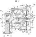
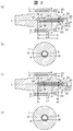
- FIG. 1 is a longitudinal sectional view showing a first embodiment of a motor according to the present invention. It is an enlarged view of the oil storage part of Example 1 shown in FIG. 1, (a) is the longitudinal cross-sectional view which showed the relationship between the oil of a motor stop state, and a temperature sensor, (b) is FIG. 2 (a).
- FIG. 3A is a longitudinal sectional view showing the relationship between the oil in the motor driving state and the temperature sensor
- FIG. 2D is a CC arrow view of FIG. 2C.
- (a) is the longitudinal cross-sectional view which showed the relationship of the oil of a motor stop state, a temperature sensor, and a communicating hole
- (b) is a motor drive state
- FIG. 1 shows a first embodiment of the motor according to the present invention.
- Example 1 although the form with which the magnet was embed
- the illustrated motor 100 includes a rotor 1 and a stator 2 disposed around an outer peripheral surface 1 ⁇ / b> A of the rotor 1, and a coil 3 is wound around the stator 2 a plurality of times. Are driven to rotate about the rotation axis L as the center of rotation. A magnet 9 is embedded in the rotor 1 along the outer peripheral surface 1A.
- a motor case 51 having a water jacket 52 for recirculating cooling water is provided on the outside of the stator 2. Accordingly, the outer peripheral surfaces of the rotor 1 and the stator 2 can be protected from the external environment, and the heat released from the rotor 1 and the like can be absorbed by the internal cooling water to cool the rotor 1 and the stator 2 and the like.
- a motor cover 20 including an outer lid 21 and an inner lid 22 is provided on one end side in the direction of the rotation axis L of the rotor 1.
- a substrate 28 is provided on a surface 22A of the inner cover 22 of the motor cover 20 that faces the outer cover 21, and an inverter circuit 24 having a temperature calculating means 27 for calculating the rotor temperature and the magnet temperature is provided on the substrate 28.
- the inverter circuit 24 is further provided with a rotation control means 26, and a signal from the rotation angle sensor 25 provided on the rotor 1 side of the inner lid 22 for detecting the rotation of the rotor 1 and a temperature calculation means 27. Based on the calculated rotor temperature and magnet temperature, the rotational speed of the rotor 1 can be controlled. Further, bearings 53 and 23 are provided between the motor case 51 and the rotor 1 and between the inner lid 22 and the rotor 1, respectively, so that the rotor 1 rotates relative to the motor case 51 and the inner lid 22. It can be done.
- an oil reservoir 4 for storing oil P on the rotation axis L of the rotor 1 is provided.
- the oil reservoir 4 is formed in a substantially cylindrical shape coaxial with the rotation axis L of the rotor 1.
- an opening 29 is formed in a substantially central portion (on the rotation axis L of the rotor 1) of the inner cover 22 of the motor cover 20, and the temperature sensor 30 is inserted along the rotation axis L through the opening 29.
- the flange 33 is attached to the inner lid 22.
- the temperature sensor 30 is attached and fixed to the inner lid 22 by engaging and fixing the flange portion 33 of the temperature sensor 30 with the outer peripheral portion of the opening 29 of the inner lid 22.
- the temperature sensor 30 is formed in a substantially cylindrical shape that is coaxial with the rotation axis L of the rotor 1. As described above, the temperature sensor 30 is inserted along the rotation axis L, and is attached to the inner lid 22 by the flange portion 33, so that the entire temperature sensor 30 extends along the rotation axis L in the oil reservoir 4. This results in insertion without contacting the rotor 1.
- the outer diameter of the temperature sensor 30 is set to be relatively smaller than the inner diameter of the oil reservoir 4, and the temperature sensor 30 formed in a substantially cylindrical shape on the rotation axis L of the rotor 1 as described above is Even if the rotor 1 rotates around the temperature sensor 30 in a state where the temperature sensor 30 is fixed to the motor cover 20 by being arranged without contacting the inner surface of the substantially cylindrical oil reservoir 4, The inner peripheral surface of the oil reservoir 4 and the outer peripheral surface of the temperature sensor 30 are not in contact with each other and are not worn.
- the oil reservoir 4 stores a predetermined amount of oil P.
- the temperature sensor 30 and the oil P are in direct contact, and the temperature sensor 30 and the rotor 1 are oiled. Heat is transferred through P. That is, the heat radiated from the rotor 1 is transmitted to the oil P and further transmitted to the temperature sensor 30, whereby the temperature of the rotor 1 can be detected by measuring the temperature of the oil P by the temperature sensor 30.
- an oil seal 6 is interposed between the rotor 1 and the temperature sensor 30, and the temperature sensor 30 is fixed to the motor cover 20 as shown in the figure, and the rotor 1 is relative to the temperature sensor 30. Even in the case of rotation, the oil seal 6 can prevent the oil P in the oil reservoir 4 from leaking out of the rotor 1.
- the temperature sensor 30 is generally configured by a casing 35 and a temperature detection unit 36 that include a cylindrical portion 31 extending in the direction of the rotation axis L of the rotor 1 and a bottom portion 32 that closes one end of the cylindrical portion 31. .
- the temperature detector 36 is attached to the inner peripheral surface of the cylindrical portion 31, and the casing 35 is open at the end opposite to the bottom 32.
- the inverter circuit 24 is connected through an open portion at the opposite end. Thereby, the detection signal of the temperature of the oil P measured by the temperature detection unit 36 is transmitted to the temperature calculation means 27 and the rotation control means 26 in the inverter circuit 24, and the calculation of the temperature of the rotor 1 and the magnet 9 or the rotor 1 It is used for controlling the rotation speed.
- the temperature detection unit 36 and the oil P to be measured can be arranged close to each other, and the responsiveness is better. Precise temperature measurement is possible.
- the temperature detection unit 36 include a thermistor and a thermocouple.
- the speed reducer 40 is provided on the side of the motor case 51 opposite to the side on which the motor cover 20 is attached.
- the speed reducer 40 is generally configured by a housing 41 that defines an oil storage chamber 42 and a gear 43 that is provided on a shaft 44 disposed in the housing 41, and the gear 10 and the gear that are provided at the end of the rotor 1.
- a bearing 45 is provided between the housing 41 and the shaft 44 so that the shaft 44 can rotate relative to the housing 41.
- the rotor 1 in which the magnet 9 is embedded along the outer peripheral surface 1A and the stator 2 around which the coil 3 is wound are prepared, and the end on the opposite side to the side on which the water jacket 52 and the motor cover 20 are attached is prepared.
- a motor case 51 having a bearing 53 attached thereto is prepared.
- the stator 2 is inserted into the motor case 51 from the side where the motor cover 20 is attached.
- the step 2 provided on the inner peripheral surface of the motor case 51 is brought into contact with the corner portion of the stator 2, whereby the stator 2 is positioned with respect to the motor case 51.
- the rotor 1 is inserted into the motor case 51 from the same direction as the insertion direction of the stator 2 until the step 7 provided on the rotor 1 contacts the bearing 53.
- the motor cover 20 is prepared in a process separate from the above process. That is, the substrate 28 is attached to the one surface 22A of the inner lid 22 of the motor cover 20, and the inverter circuit 24 including the temperature calculating means 27 and the rotation control means 26 is placed thereon. Further, a rotation sensor 25 and a bearing 23 are disposed on the other surface of the inner lid 22 opposite to the one surface 22A. An opening 29 is provided at substantially the center of the inner lid 22. The temperature sensor 30 is inserted through the opening 29 in the direction of the rotation axis L of the rotor 1, and the inner lid is formed by a flange 33 at the end thereof. Attach to 22. Note that the rotation sensor 25 and the temperature sensor 30 are connected to the inverter circuit 24 by a lead wire (not shown).
- the motor cover 20 is formed by attaching the outer lid 21 to the inner lid 22 so as to cover one surface 22A of the inner lid 22, that is, the inverter circuit 24.
- the method for attaching the outer lid 21 and the inner lid 22 include an attachment method using a fitting claw, an attachment method using a fastening member such as a bolt or a screw, an attachment method using an adhesive or the like.
- the motor cover 20 is prepared for mounting, and after a desired amount of oil P is injected into the oil reservoir 4 of the rotor 1, a part of the temperature sensor 30 of the motor cover 20 is inserted into the oil reservoir 4.
- the motor cover 20 is attached to the motor case 51 along the rotation axis L.
- the corner 34 at the tip of the temperature sensor 30 has a tapered shape so that the temperature sensor 30 can be guided to the oil reservoir 4.
- An oil seal 6 is provided at the end of the oil reservoir 4 of the rotor 1 so that the oil P does not leak from the oil reservoir 4 to the outside of the rotor 1 after the temperature sensor 30 is inserted into the oil reservoir 4. Arranged between the rotor 1 and the temperature sensor 30.
- FIG. 2 shows the relationship between the oil P injected into the oil reservoir 4 and the temperature sensor 30 in the first embodiment
- FIG. 2 (a) shows the motor stop state
- FIG. 2B is a view taken along the line AA in FIG. 2A
- FIG. 2C shows the motor driving state
- FIG. 2D is a cross-sectional view taken along the line CC in FIG. It is an arrow view.
- the motor 100 of the first embodiment is applied to a vehicle
- the motor 100 is attached to the vehicle so that the rotation axis L of the rotor 1 is horizontal as shown in FIGS.
- the oil P is below the oil reservoir 4 when the motor 100 is stopped. It is in the accumulated state.
- the oil P is transferred between the temperature sensor 30 and the rotor 1 as shown in FIG. That is, the oil P is stored in the oil reservoir 4 so that the space between the lower portion of the oil reservoir 4 of the rotor 1 and the lower portion of the temperature sensor 30 (the temperature detector 36) is filled with the oil P. Need to be.
- the oil P in the oil reservoir 4 is pushed outward in the radial direction of the oil reservoir 4 by the centrifugal force, and oil is applied to the inner peripheral surface of the oil reservoir 4.
- a P (heat transfer) layer is formed.
- the oil P is an oil between the rotor 1 and the temperature sensor 30 as shown in FIG.
- the amount filled with the P layer that is, ⁇ (D 2 -d 2 ) L1 / 4 or more needs to be stored.
- D is the inner diameter of the oil reservoir 4
- d is the outer diameter of the temperature sensor 30
- L1 is the length of the oil reservoir 4 in the axis L direction.
- the temperature detection unit 36 of the temperature sensor 30 accurately adjusts the temperature of the oil P with high responsiveness.
- the temperature detector 36 is attached to the outer side in the radial direction with respect to the rotation axis L of the rotor 1, that is, attached to the inner peripheral surface of the cylindrical portion 31 of the temperature sensor 30. preferable.
- the temperature detector 36 of the temperature sensor 30 is attached to the lower side of the inner peripheral surface of the cylindrical portion 31 in particular.
- the inner peripheral surface of the portion to which the temperature detection unit 36 is attached and the rotor 1 are always in heat transfer via the oil P, and the temperature detection unit 36 can measure the oil P temperature with good responsiveness.
- the oil P in the oil reservoir 4 is mainly stored vertically downward, so that the temperature detector 36 is below the inner peripheral surface of the cylindrical portion 31 of the temperature sensor 30.
- it is attached to the side.
- the temperature detector 36 is attached to the vertically lower side of the inner peripheral surface of the cylindrical portion 31 of the temperature sensor 30 as in the first embodiment, so that the rotor can be efficiently operated regardless of the rotational speed of the rotor 1. 1 heat can be transmitted to the temperature detector 36, and the heat transfer characteristics from the rotor 1 can be stabilized.
- the oil P in the oil reservoir 4 needs to be stored by ⁇ D 2 (L1-L2) / 4 or more.
- L2 is the length of the temperature sensor 30 in the oil reservoir 4 in the direction of the axis L.
- the temperature detector 36 is used as a temperature sensor in order to measure the temperature of the oil P with good responsiveness especially when the motor 100 is stopped. It can also be provided on the inner surface of the bottom 32 of 30.
- the contact area between the temperature detection means 30 and the oil P can be increased, and the temperature P can be measured more efficiently by the temperature detector 36.
- the mounting position of the temperature detector 36 and the rotor 1 can be set regardless of whether the rotation axis L of the rotor 1 is horizontal or vertical. Regardless of the rotation speed of the oil P, the temperature of the oil P can be accurately measured.
- Example 1 when measuring the oil temperature to which the heat from the rotor 1 is transmitted by the temperature detection unit 36, by measuring the temperature of the oil P stored in the oil storage unit 4, The temperature of the oil P can be measured without considering the influence of the inflow temperature, the flow rate, the flow velocity, etc. of the oil P, and the temperature of the rotor 1 can be detected accurately based on the measurement result.
- calibration information of the temperature of the oil P and the temperature of the rotor 1 obtained in advance may be used.
- the temperature of the magnet 9 embedded in the rotor 1 which can be higher than those temperatures is also the motor driving state (rotor rotational speed and torque), energy loss (iron loss) corresponding to the driving state, Based on the obtained thermal resistance and heat capacity of the rotor 1, the magnet temperature can be accurately calculated using the temperature calculating means 27. Then, based on these calculated temperatures, the rotation control means 26 can precisely control the rotation of the rotor 1 so that the rotor temperature and the magnet temperature do not exceed the limit temperature. High torque can be realized.
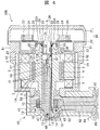
- Example 2 Next, a second embodiment of the motor according to the present invention will be described in detail with reference to FIG.
- symbol is attached
- the rotor 1 includes the oil supply path 8 that extends along the rotation axis L from the bottom of the oil reservoir 4 to the end of the rotor 1 on the speed reducer 40 side. 1 is different.
- the housing 41 forms an oil supply path 48, and the oil supply path 48 communicates with an oil reservoir 47 and an oil storage chamber 42 defined by the end of the rotor 1 and the housing 41.
- the oil in the oil storage chamber 42 can flow into the oil supply path 8 through the oil reservoir 47.
- An oil seal 46 is provided between the rotor 1 and the housing 41 so that the oil in the oil reservoir 47 does not leak into the oil storage chamber 42.
- the motor cover 20 when the motor cover 20 is attached to the motor case 51, it is not necessary to inject oil P into the oil reservoir 4 in advance. That is, when attaching the motor cover 20 to the motor case 51, a part of the temperature sensor 30 is inserted into the oil storage unit 4 in a state where the oil P is not stored in the oil storage unit 4. Then, after attaching the motor cover 20 and the speed reducer 40 to the motor case 20, the coil 3 of the motor 200 is energized, the rotor 1 is rotated at a desired rotational speed, and the shaft 44 of the speed reducer 40 is rotated. Then, the oil P stored in the oil storage chamber 42 of the housing 41 is diffused into the oil supply path 48 and flows.
- the oil P that has flowed into the oil supply path 48 is supplied to the oil supply path 8 of the rotor 1 via the oil reservoir 47 and further supplied to the oil storage section 4 that is in fluid communication with the oil supply path 8. .
- an on-off valve (not shown) may be provided in the oil supply path 48, and after the desired amount of oil P is stored in the oil reservoir 4, the on-off valve is closed to stop oil supply. Good.
- the height of the vertical top portion of the oil supply passage 48 formed in the housing 41 is set to be relatively higher than the vertical height of the oil storage portion 4, the oil P can be reliably supplied to the rotor 1.
- the oil can be supplied to the oil reservoir 4.
- the oil reservoir 4 is replenished to the oil reservoir 4 via the oil supply path 8 to obtain a desired amount.
- Oil P can be stored.
- the oil pressure in the oil supply path 8 is adjusted and the oil P is discharged from the oil storage section 4 to the oil supply path 8. You can also.
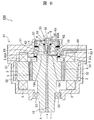
- Example 3 Next, a third embodiment of the motor according to the present invention will be described in detail with reference to FIG.
- symbol is attached
- the motor 300 according to the third embodiment is different in that the oil supply path 8 of the motor 200 according to the second embodiment is configured with an oil inflow path 11 and an oil outflow path 13.
- an oil circulation path 18 mainly including an oil inflow path 11 and an oil outflow path 13 in the rotor 1 and an oil storage chamber 42 and an oil supply path 48 in the housing 41 is provided.
- the oil P having a high thermal conductivity stored in the oil storage chamber 42 circulates inside the oil circulation path 18 so that heat released from the rotor 1 can be sucked to cool the rotor 1.
- the oil circulation path 18 is secured in the motor 300 of the third embodiment. Therefore, the lengths of the oil reservoir 4 and the temperature sensor 30 in the direction of the rotation axis L are relatively shorter than those of the first and second embodiments.
- the oil circulation path 18 will be described in detail. First, when the coil 3 of the motor 300 is energized and the rotor 1 and the shaft 44 rotate, the oil stored in the oil storage chamber 42 diffuses into the oil supply path 48 and flows in. After that, it passes through the oil reservoir 47 and flows into the oil inflow passage 11 through the inlet 12 formed at the end of the rotor 1.
- the oil in the oil inflow passage 11 mainly flows in the direction of the rotation axis L of the rotor 1, and near the end on the opposite side of the oil inflow passage 11, passes through the radial connecting passage 15 provided there, and the oil inflow passage 11. Flows radially outward.
- An oil outflow path 13 that is in fluid communication with the connection path 15 is provided outside the oil inflow path 11 in the radial direction.
- the oil that has flowed into the connection path 15 passes through the oil outflow path 13 through the rotation axis of the rotor 1.
- the oil flows in the L direction (the direction opposite to the inflow direction) and is discharged to the oil storage chamber 42 through the outlet 14 formed at the end of the oil outflow passage 13.
- the oil circulation path 18 of the oil P for cooling the rotor is formed, and the oil P absorbs the heat of the rotor 1 while passing through the oil inflow path 11, the oil outflow path 13, and the connection path 15, and the rotor 1 and the like.
- the heat released from the heat is radiated to the outside of the motor 300.
- the oil outflow passage 13 is provided radially outside the oil inflow passage 11 so that the heat released from the rotor 1 is mainly absorbed by the oil in the oil outflow passage 13. Since it can be quickly discharged to the outside of the rotor 1, the rotor 1 can be efficiently cooled.
- the oil inflow path 11, the oil outflow path 13, and the like of the oil circulation path 18 are separated from the oil reservoir 4 by the partition wall 17, a communication hole is formed at the approximate center of the partition wall 17 (on the rotation axis L of the rotor 1).
- the oil inflow passage 11 and the oil reservoir 4 are in fluid communication via the communication hole 16.
- a part of the oil P flowing through the oil circulation path 18 is supplied to the oil storage chamber 4 through the communication hole 16, so that in the third embodiment as well, as in the second embodiment, the oil storage section 4 in advance.
- the coil 3 of the motor 300 is energized to rotate the rotor 1 at a desired rotational speed, and the oil P in the oil storage chamber 42 is supplied to the oil reservoir 4.
- a spiral groove (not shown) is formed in advance on a part of the oil inflow passage 11 and the inner peripheral surface of the communication hole 16. You may guide to the storage part 4.
- an open / close valve (not shown) is provided in the oil outflow path 13, the connecting path 15, etc., and the open / close valve is closed until a desired amount of oil P is stored in the oil storage section 4.
- the connecting path 15 may be closed, and then the on-off valve may be opened to circulate the oil P through the oil circulation path 18.
- the oil circulating in the oil circulation path 18 through the communication hole 16 is also used. Since a part of the oil reservoir 4 can be replenished, a desired amount of oil P can be stored in the oil reservoir 4.
- FIG. 5 shows the relationship between the oil P injected into the oil reservoir 4 and the temperature sensor 30 in the third embodiment, and FIG. 5 (a) shows the motor stop state. b) shows the motor drive state.
- the oil P is below the oil reservoir 4 when the motor 300 is stopped. It is in a state accumulated in.
- the communication hole 16 is provided, so that the oil P is temporarily supplied into the oil storage unit 4 in a larger amount than the predetermined amount, and stored so as to be higher than the height of the communication hole 16. In this case, unnecessary oil P stored at a position higher than the communication hole 16 can be discharged to the oil inflow passage 11 through the communication hole 16.
- the amount of oil P stored in the oil storage unit 4 can be limited below the communication hole 16 to optimize the amount of oil P in the oil storage unit 4.
- the inner diameter A of the communication hole 16 is set as much as possible. It is preferable to make it small. It should be noted that the oil P in the oil reservoir 4 can be stored up to a position higher than the communication hole 16 by adjusting the pressure of the oil flowing through the oil inflow passage 11.
- the rotation axis L is assumed to be vertical, that is, the motor cover 20 is vertical.
- the motor 300 is arranged on the vehicle so as to be on the upper side, the oil P accumulated at the end (vertically below) on the opposite side to the motor cover 20 of the oil reservoir 4 passes to the oil inflow passage 11 through the communication hole 16. There is a possibility of being discharged. Therefore, in this Example 3, it is preferable to arrange
- the oil pressure in the oil inflow passage 11 is adjusted, for example, a one-way valve or the like is provided in the communication hole 16.
- the oil P can be prevented from being discharged to the oil inflow path 11.
- the oil P inside the oil reservoir 4 is pushed outward in the radial direction of the oil reservoir 4 by the centrifugal force, and on the inner peripheral surface of the oil reservoir 4. A layer of oil P is formed. Even in such a state, in order to accurately detect the temperature of the rotor 1 by the temperature sensor 30, the oil P is stored in the oil storage unit 4 at least ⁇ (D 2 -d 2 ) L 1/4 as in the first embodiment. Need to be.
- Example 3 since a part of the oil P circulated for cooling the rotor 1 is stored in the oil reservoir 4 and the temperature of the rotor 1 can be detected through the stored oil P, the circulation is performed.
- the temperature of the rotor 1 can be detected with high accuracy by suppressing the influence of the circulating state such as the inflow temperature, flow rate, and flow rate of the oil P to be performed.
- the oil P can be stored in the oil storage unit 4 using the circulating oil P, a step of injecting the oil P from the outside into the oil storage unit 4 in advance is not required, and the manufacturing process of the motor is simplified. Can do.
- FIG. 6 shows an embodiment in which a lubricating oil having a high thermal conductivity for cooling the bearing is used as the oil P stored in the oil storage section 4.
- the lubricating oil P flows from one end portion of the rotor 1 through an oil supply path 19 provided along the rotation axis L of the rotor 1 and in a radial direction provided in the vicinity of the end portion on the oil storage portion 4 side.
- an oil discharge path 19 ⁇ / b> A that extends, the oil is delivered to an oil storage portion 64 that is defined by an inner surface 60 ⁇ / b> A of the motor cover 60, the rotor 1, and oil seals 61 and 62.
- the oil storage part 64 accommodates a bearing 63 attached to the inner surface 60 ⁇ / b> A of the motor cover 60, and the bearing 63 is cooled by the oil PA in the oil storage part 64.
- the oil PA that has become high temperature by absorbing the heat of the bearing 63 is discharged to the outside of the motor 400 through an oil discharge path 69 formed inside the motor cover 60.
- the oil supply passage 19 is supplied with lubricating oil from an oil storage chamber (not shown) for lubricating oil.
- a rotation angle sensor 65 is attached to the inner surface 60A of the motor cover 60 and is connected to a rotation control means (not shown) so that the rotation speed of the rotor 1 can be controlled.
- a rotation control means not shown
- an opening 68 is provided at substantially the center of the motor cover 60 (on the rotation axis L of the rotor 1), and the temperature sensor 30 is attached so as to penetrate the opening 68.
- a partition wall 17 is provided between the oil supply path 19 and the oil reservoir 4 as in the third embodiment, and a communication hole 16 is provided at the approximate center of the partition wall 17. Part of the oil P that has flowed through the oil supply path 19 is supplied to the oil reservoir 4.
- the motor cover 60 when the motor cover 60 is attached to the motor case 51, it is not necessary to inject the oil P into the oil reservoir 4 in advance. That is, after attaching the motor cover 60 to the motor case 51, the rotor 1 is rotated at a desired rotational speed, and a part of the oil P flowing through the oil supply path 19 is supplied to the oil reservoir 4 through the communication hole 16. be able to.
- the rotor temperature can be detected through the oil stored in the oil storage section.
- the rotor temperature can be detected easily and accurately based on the measurement results. can do.
- the magnet temperature can be accurately calculated based on the detected rotor temperature, etc., so the rotational speed of the rotor is controlled to reduce the magnet demagnetization. Can be suppressed.
- the motor can be driven with high torque and high efficiency over a long period of time.
- the present invention is not limited to the first to fourth embodiments described above, and includes various modifications.
- the first to fourth embodiments described above are described in detail for easy understanding of the present invention, and are not necessarily limited to those having all the configurations described.
- a part of the configuration of one embodiment can be replaced with the configuration of another embodiment, and the configuration of another embodiment can be added to the configuration of one embodiment.
- control lines and information lines indicate what is considered necessary for the explanation, and not all the control lines and information lines on the product are necessarily shown. In practice, it may be considered that almost all the components are connected to each other.
Landscapes
- Engineering & Computer Science (AREA)
- Power Engineering (AREA)
- Microelectronics & Electronic Packaging (AREA)
- Mechanical Engineering (AREA)
- General Engineering & Computer Science (AREA)
- Motor Or Generator Cooling System (AREA)
Abstract
Description
2 ステータ
3 コイル
4 オイル貯留部
6 オイルシール
7 段差
8,19 オイル供給路
9 磁石
10 ギア
11 オイル流入路
12 流入口
13 オイル流出路
14 流出口
15 連結路
16 連通孔
17 隔壁
18 オイル循環路
19A オイル排出路
20,60 モータカバー
21 外蓋
22 内蓋
23,63 ベアリング
24 インバータ回路
25,65 回転角センサ
26 回転制御手段
27 温度算出手段
28 基板
29,68 開口部
30 温度センサ
31 円筒部
32 底部
33 鍔部
34 角部
35 筐体
36 温度検出部
40 減速機
41 ハウジング
42 オイル貯蔵室
43 ギア
44 シャフト
45 ベアリング
46 オイルシール
47 オイル溜まり
48 オイル供給路
51 モータケース
52 ウォータジャケット
53 ベアリング
54 段差
61,62 オイルシール
64 オイル貯蔵部
69 オイル排出路
100,200,300,400 モータ
A 連通孔内径
D オイル貯留部内径
d 温度センサ外径
L ロータ回転軸線
P,PA オイル
図1は、本発明に係るモータの実施例1を示したものである。なお、実施例1においては、ロータ内部に磁石が埋設された形態について説明するが、ロータ内部に磁石が埋設されていない形態についても同様の構成を適用することができる。
次に、図3を参照して、本発明に係るモータの実施例2について詳細に説明する。なお、同図において実施例1と同様の構成については、同じ符号を付してその詳細な説明を省略する。
次に、図4を参照して、本発明に係るモータの実施例3について詳細に説明する。なお、同図において実施例1,2と同様の構成については、同じ符号を付してその詳細な説明を省略する。
次に、図6を参照して、本発明に係るモータの実施例4について詳細に説明する。なお、同図において実施例1~3と同様の構成については、同じ符号を付してその詳細な説明を省略する。
Claims (9)
- ロータと、該ロータの周りに配置されたステータと、温度センサと、を備えたモータであって、
前記ロータは、その内部の回転軸線上にオイルを貯留するオイル貯留部を備え、
前記温度センサは、前記オイル貯留部に貯留されている前記オイルの温度を検出するものであることを特徴とするモータ。 - 前記温度センサは、前記モータのモータカバーにその一端部が取り付けられ、他端部が前記ロータの前記回転軸線上の前記オイル貯留部に挿入配置されると共に、前記オイルに接触していることを特徴とする請求項1に記載のモータ。
- 前記温度センサは、円筒部と底部とを有する筺体と、前記円筒部の内周面に配置される温度検出部と、を備えていることを特徴とする請求項1又は2に記載のモータ。
- 前記温度センサと前記ロータとの間に、前記オイル貯留部に貯留されている前記オイルが前記ロータ外に漏れるのを防止するオイルシールが配置されていることを特徴とする請求項2又は3に記載のモータ。
- 前記温度検出部は、前記モータの下方側の前記円筒部の前記内周面に配置されることを特徴とする請求項3に記載のモータ。
- 前記モータは、オイル貯蔵室を備えると共に、前記ロータは、その内部の前記回転軸線上にオイル供給路を備え、前記オイル貯蔵室と前記オイル貯留部とは、前記オイル供給路を介して連通していることを特徴とする請求項1から5のいずれかに記載のモータ。
- 前記オイル供給路は、少なくともオイル流入路とオイル流出路から成るオイル循環路で構成されていることを特徴とする請求項6に記載のモータ。
- 前記ロータは、前記オイル循環路と前記オイル貯留部とを連通させる連通孔を備え、該連通孔は、前記回転軸線上に穿設されていることを特徴とする請求項7に記載のモータ。
- 前記モータは、前記温度検センサで検出されたオイル温度からロータ温度及び/又は前記ロータ埋設の磁石の温度を算出する温度算出手段を備えていることを特徴とする請求項1から8のいずれかに記載のモータ。
Priority Applications (4)
| Application Number | Priority Date | Filing Date | Title |
|---|---|---|---|
| EP11859572.7A EP2680410A4 (en) | 2011-02-21 | 2011-02-21 | Motor |
| JP2013500719A JP5624667B2 (ja) | 2011-02-21 | 2011-02-21 | モータ |
| PCT/JP2011/053638 WO2012114419A1 (ja) | 2011-02-21 | 2011-02-21 | モータ |
| US13/980,449 US20130294888A1 (en) | 2011-02-21 | 2011-02-21 | Motor |
Applications Claiming Priority (1)
| Application Number | Priority Date | Filing Date | Title |
|---|---|---|---|
| PCT/JP2011/053638 WO2012114419A1 (ja) | 2011-02-21 | 2011-02-21 | モータ |
Publications (1)
| Publication Number | Publication Date |
|---|---|
| WO2012114419A1 true WO2012114419A1 (ja) | 2012-08-30 |
Family
ID=46720241
Family Applications (1)
| Application Number | Title | Priority Date | Filing Date |
|---|---|---|---|
| PCT/JP2011/053638 Ceased WO2012114419A1 (ja) | 2011-02-21 | 2011-02-21 | モータ |
Country Status (4)
| Country | Link |
|---|---|
| US (1) | US20130294888A1 (ja) |
| EP (1) | EP2680410A4 (ja) |
| JP (1) | JP5624667B2 (ja) |
| WO (1) | WO2012114419A1 (ja) |
Cited By (6)
| Publication number | Priority date | Publication date | Assignee | Title |
|---|---|---|---|---|
| US20140126606A1 (en) * | 2012-11-02 | 2014-05-08 | Honda Motor Co., Ltd. | Method of estimating magnet temperature for rotary electric machinery |
| CN104158374A (zh) * | 2014-08-21 | 2014-11-19 | 江西工埠机械有限责任公司 | 设有定子内置温度传感器的永磁同步电机及疲劳测定方法 |
| CN104823370A (zh) * | 2012-11-28 | 2015-08-05 | 日立汽车系统株式会社 | 电动机、控制装置和电动机驱动装置 |
| US10594193B2 (en) | 2017-11-16 | 2020-03-17 | Fanuc Corporation | Holder, electric motor, and temperature detection element fixing method |
| JP2021092204A (ja) * | 2019-12-11 | 2021-06-17 | ダイハツ工業株式会社 | 油路構造 |
| CN113078758A (zh) * | 2021-04-28 | 2021-07-06 | 舍弗勒技术股份两合公司 | 电机及同轴电桥驱动系统 |
Families Citing this family (4)
| Publication number | Priority date | Publication date | Assignee | Title |
|---|---|---|---|---|
| JP5149431B2 (ja) * | 2011-07-29 | 2013-02-20 | ファナック株式会社 | 電動機の可動子の温度を検出する温度検出装置 |
| CN106256077B (zh) * | 2014-05-09 | 2018-08-24 | 本田技研工业株式会社 | 旋转电机的磁铁温度推断装置以及旋转电机的磁铁温度推断方法 |
| JP6272526B1 (ja) * | 2017-04-25 | 2018-01-31 | 三菱電機株式会社 | 回転電機 |
| JP7106892B2 (ja) * | 2018-03-06 | 2022-07-27 | 日産自動車株式会社 | 回転電機 |
Citations (4)
| Publication number | Priority date | Publication date | Assignee | Title |
|---|---|---|---|---|
| JPH04127857A (ja) * | 1990-09-19 | 1992-04-28 | Toshiba Mach Co Ltd | 回転子冷却制御装置 |
| JP2000023421A (ja) | 1998-06-30 | 2000-01-21 | Toyota Motor Corp | ロータ温度推定方法 |
| JP2008178243A (ja) | 2007-01-19 | 2008-07-31 | Toyota Motor Corp | 磁石温度推定装置、磁石保護装置および磁石温度推定方法、磁石保護方法 |
| JP2008228524A (ja) * | 2007-03-15 | 2008-09-25 | Hitachi Via Mechanics Ltd | 揺動アクチュエータ装置およびレーザ加工装置 |
Family Cites Families (9)
| Publication number | Priority date | Publication date | Assignee | Title |
|---|---|---|---|---|
| EP1229270A3 (en) * | 1995-12-21 | 2003-08-13 | Aisin Aw Co., Ltd. | Drive apparatus for electric vehicle |
| SE518216C2 (sv) * | 2000-04-06 | 2002-09-10 | Abb Ab | Förfarande vid drift av synkronkompensator samt sådan synkronkompensator. |
| DE10031124C2 (de) * | 2000-06-30 | 2002-05-16 | Heraeus Electro Nite Int | Sensor zur Temperaturerfassung eines Fluids |
| JP4041018B2 (ja) * | 2003-06-25 | 2008-01-30 | Tdk株式会社 | 温度センサ |
| JP2005017070A (ja) * | 2003-06-25 | 2005-01-20 | Denso Corp | 車両用サーミスタ式温度検出器 |
| JP4711776B2 (ja) * | 2005-08-11 | 2011-06-29 | 株式会社東芝 | 液冷式回転電機 |
| JP2007336646A (ja) * | 2006-06-13 | 2007-12-27 | Toshiba Corp | 回転電機 |
| JP5158861B2 (ja) * | 2008-03-11 | 2013-03-06 | Ntn株式会社 | インホイールモータ駆動装置 |
| JP2009291056A (ja) * | 2008-06-02 | 2009-12-10 | Ntn Corp | モータの冷却構造 |
-
2011
- 2011-02-21 US US13/980,449 patent/US20130294888A1/en not_active Abandoned
- 2011-02-21 JP JP2013500719A patent/JP5624667B2/ja not_active Expired - Fee Related
- 2011-02-21 EP EP11859572.7A patent/EP2680410A4/en not_active Withdrawn
- 2011-02-21 WO PCT/JP2011/053638 patent/WO2012114419A1/ja not_active Ceased
Patent Citations (4)
| Publication number | Priority date | Publication date | Assignee | Title |
|---|---|---|---|---|
| JPH04127857A (ja) * | 1990-09-19 | 1992-04-28 | Toshiba Mach Co Ltd | 回転子冷却制御装置 |
| JP2000023421A (ja) | 1998-06-30 | 2000-01-21 | Toyota Motor Corp | ロータ温度推定方法 |
| JP2008178243A (ja) | 2007-01-19 | 2008-07-31 | Toyota Motor Corp | 磁石温度推定装置、磁石保護装置および磁石温度推定方法、磁石保護方法 |
| JP2008228524A (ja) * | 2007-03-15 | 2008-09-25 | Hitachi Via Mechanics Ltd | 揺動アクチュエータ装置およびレーザ加工装置 |
Non-Patent Citations (1)
| Title |
|---|
| See also references of EP2680410A4 |
Cited By (9)
| Publication number | Priority date | Publication date | Assignee | Title |
|---|---|---|---|---|
| US20140126606A1 (en) * | 2012-11-02 | 2014-05-08 | Honda Motor Co., Ltd. | Method of estimating magnet temperature for rotary electric machinery |
| US9593986B2 (en) * | 2012-11-02 | 2017-03-14 | Honda Motor Co., Ltd. | Method of estimating magnet temperature for rotary electric machinery |
| CN104823370A (zh) * | 2012-11-28 | 2015-08-05 | 日立汽车系统株式会社 | 电动机、控制装置和电动机驱动装置 |
| EP2928050A4 (en) * | 2012-11-28 | 2016-06-08 | Hitachi Automotive Systems Ltd | ENGINE, CONTROL DEVICE AND MOTOR DRIVE UNIT |
| CN104158374A (zh) * | 2014-08-21 | 2014-11-19 | 江西工埠机械有限责任公司 | 设有定子内置温度传感器的永磁同步电机及疲劳测定方法 |
| US10594193B2 (en) | 2017-11-16 | 2020-03-17 | Fanuc Corporation | Holder, electric motor, and temperature detection element fixing method |
| JP2021092204A (ja) * | 2019-12-11 | 2021-06-17 | ダイハツ工業株式会社 | 油路構造 |
| JP7113808B2 (ja) | 2019-12-11 | 2022-08-05 | ダイハツ工業株式会社 | 油路構造 |
| CN113078758A (zh) * | 2021-04-28 | 2021-07-06 | 舍弗勒技术股份两合公司 | 电机及同轴电桥驱动系统 |
Also Published As
| Publication number | Publication date |
|---|---|
| JP5624667B2 (ja) | 2014-11-12 |
| US20130294888A1 (en) | 2013-11-07 |
| EP2680410A4 (en) | 2018-03-07 |
| JPWO2012114419A1 (ja) | 2014-07-07 |
| EP2680410A1 (en) | 2014-01-01 |
Similar Documents
| Publication | Publication Date | Title |
|---|---|---|
| JP5624667B2 (ja) | モータ | |
| JP5695013B2 (ja) | 回転電機の磁石温度推定装置及び磁石温度推定方法 | |
| US10230323B2 (en) | Motor drive device | |
| US20150097450A1 (en) | System and method for cooling an electric motor | |
| EP2684280B1 (en) | Cooled magnet motor | |
| JP2014092455A (ja) | 回転電機の磁石温度推定装置及び磁石温度推定方法 | |
| US20070278869A1 (en) | Rotating Electric Machine | |
| JP5483095B2 (ja) | 回転電機の冷却構造 | |
| JP2009213231A (ja) | 電動機 | |
| JP6294375B2 (ja) | 冷媒の温度推定装置及び回転電機の温度推定装置 | |
| US20220194230A1 (en) | Drive device and vehicle drive system | |
| CN105579270A (zh) | 车轮用驱动装置 | |
| JP2009071923A (ja) | 電動モータの冷却構造 | |
| JP5473626B2 (ja) | インホイールモータ冷却装置 | |
| WO2015170747A1 (ja) | 回転電機の磁石温度推定装置および回転電機の磁石温度推定方法 | |
| US20220216820A1 (en) | Drive device | |
| US9935527B2 (en) | Temperature estimation apparatus for rotating electric machine | |
| US11431227B2 (en) | Systems and methods for providing direct spray cooling in an electric motor | |
| GB2516644A (en) | A Magnetic Coupling | |
| JP6841747B2 (ja) | 回転電機の冷却装置、および回転電機の冷却方法 | |
| US20220185122A1 (en) | Drive device | |
| JP6760103B2 (ja) | 回転電機の冷却構造 | |
| US11807250B2 (en) | Control apparatus for electric motor and vehicle | |
| JP6275558B2 (ja) | マルチギャップ型回転電機 | |
| JP2016161030A (ja) | 電気自動車用駆動装置 |
Legal Events
| Date | Code | Title | Description |
|---|---|---|---|
| 121 | Ep: the epo has been informed by wipo that ep was designated in this application |
Ref document number: 11859572 Country of ref document: EP Kind code of ref document: A1 |
|
| WWE | Wipo information: entry into national phase |
Ref document number: 1302161.3 Country of ref document: GB |
|
| ENP | Entry into the national phase |
Ref document number: 2013500719 Country of ref document: JP Kind code of ref document: A |
|
| WWE | Wipo information: entry into national phase |
Ref document number: 2011859572 Country of ref document: EP |
|
| WWE | Wipo information: entry into national phase |
Ref document number: 13980449 Country of ref document: US |
|
| NENP | Non-entry into the national phase |
Ref country code: DE |