WO2012114542A1 - タイヤ加硫装置 - Google Patents
タイヤ加硫装置 Download PDFInfo
- Publication number
- WO2012114542A1 WO2012114542A1 PCT/JP2011/060741 JP2011060741W WO2012114542A1 WO 2012114542 A1 WO2012114542 A1 WO 2012114542A1 JP 2011060741 W JP2011060741 W JP 2011060741W WO 2012114542 A1 WO2012114542 A1 WO 2012114542A1
- Authority
- WO
- WIPO (PCT)
- Prior art keywords
- platen
- tire
- divided
- plate
- vulcanizing apparatus
- Prior art date
- Legal status (The legal status is an assumption and is not a legal conclusion. Google has not performed a legal analysis and makes no representation as to the accuracy of the status listed.)
- Ceased
Links
Images







Classifications
-
- B—PERFORMING OPERATIONS; TRANSPORTING
- B29—WORKING OF PLASTICS; WORKING OF SUBSTANCES IN A PLASTIC STATE IN GENERAL
- B29C—SHAPING OR JOINING OF PLASTICS; SHAPING OF MATERIAL IN A PLASTIC STATE, NOT OTHERWISE PROVIDED FOR; AFTER-TREATMENT OF THE SHAPED PRODUCTS, e.g. REPAIRING
- B29C33/00—Moulds or cores; Details thereof or accessories therefor
- B29C33/02—Moulds or cores; Details thereof or accessories therefor with incorporated heating or cooling means
- B29C33/04—Moulds or cores; Details thereof or accessories therefor with incorporated heating or cooling means using liquids, gas or steam
-
- B—PERFORMING OPERATIONS; TRANSPORTING
- B29—WORKING OF PLASTICS; WORKING OF SUBSTANCES IN A PLASTIC STATE IN GENERAL
- B29C—SHAPING OR JOINING OF PLASTICS; SHAPING OF MATERIAL IN A PLASTIC STATE, NOT OTHERWISE PROVIDED FOR; AFTER-TREATMENT OF THE SHAPED PRODUCTS, e.g. REPAIRING
- B29C33/00—Moulds or cores; Details thereof or accessories therefor
- B29C33/02—Moulds or cores; Details thereof or accessories therefor with incorporated heating or cooling means
-
- B—PERFORMING OPERATIONS; TRANSPORTING
- B29—WORKING OF PLASTICS; WORKING OF SUBSTANCES IN A PLASTIC STATE IN GENERAL
- B29C—SHAPING OR JOINING OF PLASTICS; SHAPING OF MATERIAL IN A PLASTIC STATE, NOT OTHERWISE PROVIDED FOR; AFTER-TREATMENT OF THE SHAPED PRODUCTS, e.g. REPAIRING
- B29C33/00—Moulds or cores; Details thereof or accessories therefor
- B29C33/20—Opening, closing or clamping
-
- B—PERFORMING OPERATIONS; TRANSPORTING
- B29—WORKING OF PLASTICS; WORKING OF SUBSTANCES IN A PLASTIC STATE IN GENERAL
- B29C—SHAPING OR JOINING OF PLASTICS; SHAPING OF MATERIAL IN A PLASTIC STATE, NOT OTHERWISE PROVIDED FOR; AFTER-TREATMENT OF THE SHAPED PRODUCTS, e.g. REPAIRING
- B29C35/00—Heating, cooling or curing, e.g. crosslinking or vulcanising; Apparatus therefor
- B29C35/02—Heating or curing, e.g. crosslinking or vulcanizing during moulding, e.g. in a mould
-
- B—PERFORMING OPERATIONS; TRANSPORTING
- B29—WORKING OF PLASTICS; WORKING OF SUBSTANCES IN A PLASTIC STATE IN GENERAL
- B29C—SHAPING OR JOINING OF PLASTICS; SHAPING OF MATERIAL IN A PLASTIC STATE, NOT OTHERWISE PROVIDED FOR; AFTER-TREATMENT OF THE SHAPED PRODUCTS, e.g. REPAIRING
- B29C35/00—Heating, cooling or curing, e.g. crosslinking or vulcanising; Apparatus therefor
- B29C35/02—Heating or curing, e.g. crosslinking or vulcanizing during moulding, e.g. in a mould
- B29C35/04—Heating or curing, e.g. crosslinking or vulcanizing during moulding, e.g. in a mould using liquids, gas or steam
-
- B—PERFORMING OPERATIONS; TRANSPORTING
- B29—WORKING OF PLASTICS; WORKING OF SUBSTANCES IN A PLASTIC STATE IN GENERAL
- B29D—PRODUCING PARTICULAR ARTICLES FROM PLASTICS OR FROM SUBSTANCES IN A PLASTIC STATE
- B29D30/00—Producing pneumatic or solid tyres or parts thereof
- B29D30/06—Pneumatic tyres or parts thereof (e.g. produced by casting, moulding, compression moulding, injection moulding, centrifugal casting)
- B29D30/0601—Vulcanising tyres; Vulcanising presses for tyres
- B29D30/0662—Accessories, details or auxiliary operations
-
- B—PERFORMING OPERATIONS; TRANSPORTING
- B29—WORKING OF PLASTICS; WORKING OF SUBSTANCES IN A PLASTIC STATE IN GENERAL
- B29D—PRODUCING PARTICULAR ARTICLES FROM PLASTICS OR FROM SUBSTANCES IN A PLASTIC STATE
- B29D30/00—Producing pneumatic or solid tyres or parts thereof
- B29D30/06—Pneumatic tyres or parts thereof (e.g. produced by casting, moulding, compression moulding, injection moulding, centrifugal casting)
- B29D30/0601—Vulcanising tyres; Vulcanising presses for tyres
- B29D30/0662—Accessories, details or auxiliary operations
- B29D2030/0666—Heating by using fluids
- B29D2030/0674—Heating by using non-fluid means, e.g. electrical heating
-
- B—PERFORMING OPERATIONS; TRANSPORTING
- B29—WORKING OF PLASTICS; WORKING OF SUBSTANCES IN A PLASTIC STATE IN GENERAL
- B29L—INDEXING SCHEME ASSOCIATED WITH SUBCLASS B29C, RELATING TO PARTICULAR ARTICLES
- B29L2030/00—Pneumatic or solid tyres or parts thereof
Definitions
- the present invention relates to a tire vulcanizing apparatus for vulcanizing and molding a raw tire.
- a tire vulcanizing apparatus that vulcanizes and molds a raw tire
- an outer mold (mold) filled with the raw tire is heated, and a high-temperature, high-pressure heating medium is placed in the inner space (inside the prada) of the raw tire. And is pressed in the direction of the outer mold while heating the inner wall surface of the tire. Then, vulcanization is performed by heating the raw tire from the outside and the inside with the heated outer mold and the heating medium supplied to the internal space of the raw tire.
- steam is supplied and circulated as a heating medium in the internal space of the raw tire, and heating and pressurizing medium such as nitrogen gas and hot water are sealed. .
- Patent Document 5 discloses a tire vulcanization mold apparatus in which a platen is divided in the radial direction to vary the temperature increase rate of the heating portion in order to obtain a uniform vulcanization degree throughout the tire. Has been.
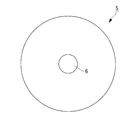
- a conventional platen 5 that performs electric heating has a donut-shaped disk shape in which a circular through hole 6 is formed in the center, and a heat generating portion 7 such as a rod-shaped heater is provided inside. It has a buried structure. For this reason, when converting to an electric platen from the viewpoint of energy saving or the like, the following problem arises because the platen 5 is a donut-shaped disk-shaped integrated structure.
- the first problem is that deformation (deflection) is likely to occur in the circular platen during tire vulcanization. For this reason, heat generating parts such as electric heaters embedded in the platen, mounting members, and the like are shortened in life due to the influence of stress generation. Further, the deformation of the platen means that the contact area between the outer mold and the heat generating portion is reduced, so that the heat transfer property (heating efficiency) is lowered. Further, when the heat transfer between the outer mold and the heat generating portion decreases, the temperature rises to an unexpectedly high temperature, thereby shortening the heat life of the heat generating portion.
- the second problem relates to the replacement of the platen at the time of maintenance or the like, and the work of replacing the integral platen requires a great deal of time for adjustment of removal and attachment. Further, when the platen is replaced due to a failure or the like, the entire platen can only be replaced at once, which is disadvantageous in terms of cost.
- the present invention has been made in view of the above circumstances, and an object of the present invention is to provide a tire vulcanizing apparatus that solves the problems associated with deformation and platen replacement during tire vulcanization of an electrically heated platen. There is.
- a tire vulcanizing apparatus is a tire vulcanizing apparatus for heating and vulcanizing a raw tire housed in an outer mold from the outside and the inside of the raw tire, and filling the raw tire
- the platen that is disposed in contact with the upper and lower parts of the container or built in the upper and lower parts of the container and that heats the raw tire from the outside of the outer mold during vulcanization is an electric type, and is a donut disk.
- the circumferential direction of the platen is divided into a plurality of parts.
- the tire vulcanizing apparatus is disposed in contact with the upper and lower sides of the container for filling the raw tire or in a state of being built in the upper and lower parts of the container, and from the outside of the outer mold at the time of vulcanization. Since the platen that heats the green tire is an electric type and the circumferential direction of the platen that is a donut-shaped disk is divided into a plurality of parts, deformation of the platen during tire vulcanization is less likely to occur.
- the radial direction of the platen is divided into a plurality of parts, and the innermost circumferential direction is connected to form a donut-shaped disk, whereby the deformation of the platen during tire vulcanization is performed. Is more difficult to occur.
- the donut-shaped disk divided platen formed in the innermost central part becomes a small-diameter circle formed in the central part of the platen, and can be used for centering during mounting.
- the platen includes a concavo-convex engaging portion that is divided into a plurality of parts and is connected and positioned by engaging the concavo-convex portions between adjacent divided platens.
- the platen may be provided with a fastening connection portion that is divided into a plurality of parts and is connected and positioned by a fastening member between adjacent divided platens.
- the platen may include a plate connecting portion that is divided into a plurality of parts and is connected and positioned between adjacent divided platens via a plate-like member.
- the platen is divided into a plurality of parts, and the adjacent divided platens include two or more of the concave and convex engaging portion, the fastening connecting portion, and the plate connecting portion. But you can. Positioning and connection between the divided platens can be easily performed by the concave / convex engagement portion, the fastening connection portion, the plate connection portion, and the combination thereof.
- the plate connecting portion is connected and positioned by engaging an uneven portion provided on the upper surface or the lower surface of the platen and an uneven portion provided on the lower surface or the upper surface of the plate member.
- the divided platen and the plate-like member may be connected and positioned via a fastening member.
- the electric heating platen of the tire vulcanizing apparatus has a structure in which the circumferential direction is divided into a plurality of parts, so that deformation due to a load at the time of tire vulcanization hardly occurs, and as a result, the heating efficiency Durability and reliability are improved.
- the structure in which the circumferential direction of the electric heating platen is divided into a plurality of parts facilitates the work of attaching / detaching and replacing the platen, and is effective in improving maintainability.
- the structure in which the electric heating platen is divided into a plurality of parts makes it possible to select the optimal division shape according to the structure of the vulcanizer, the tire mold, and the heating specifications, which is effective in improving the degree of freedom in equipment design. It is. In other words, not only is electric heating combined with bar heaters or planar heaters easy, but also the combination of electric heating and heating medium heating is easy, so the tire heating temperature can be made uniform and optimized. Thus, by reducing the heating running cost and improving the control accuracy of the heating temperature, a tire vulcanizing apparatus capable of manufacturing a high-quality tire is obtained.
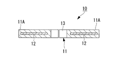
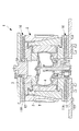
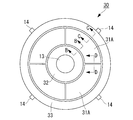
- FIG. 1 is a view showing a structure of a platen (hot plate) as an embodiment of a tire vulcanizing apparatus according to the present invention, and is a longitudinal sectional view (AA sectional view) of FIG. 1A. It is a longitudinal cross-sectional view which shows the structural example of the tire vulcanizer provided with the platen shown in FIG. It is a top view which shows the 1st modification of the platen shown in FIG. It is a top view which shows the 2nd modification of the platen shown in FIG.
- FIG. 1 It is a figure which shows the structural example of a fastening connection part, and is the structural example which piled up the uneven
- FIG. 10A It is a figure which shows the structural example of a plate connection part, and is a structural example which fastened the division
- a tire vulcanizer 1 shown in FIG. 2 is an apparatus that heats a raw tire T inside a container (mold) 2 to perform vulcanization molding.
- the container 2 includes an outer mold (mold) 3 that fills a raw tire T therein and a prada 4 that forms an internal space of the tire.
- the outer mold 3 described above is divided into a plurality of members in order to allow the raw tire T to be filled and the tire to be taken out after vulcanization.
- the outer mold 3 filled with the raw tire T is heated, and a high-temperature and high-pressure heating medium is supplied into the prada 4 that forms the internal space of the raw tire T.
- the inner wall surface of T is pressed in the direction of the outer mold 3 while being heated.
- the raw tire T is heated from the outside and the inside by the heated outer mold 3 and the heating medium supplied into the prada 4 to perform vulcanization molding.
- the raw tire T accommodated in the outer mold 3 is heated by separate platens (hot plates) 10 disposed above and below the container 2.
- the platen 10 may be built in the upper part or the lower part of the container 2.
- the platen 10 is an electric type in which a heating unit 12 such as a rod heater or a planar heater is embedded in a main body 11 having a donut-shaped disk shape.
- a heating unit 12 such as a rod heater or a planar heater
- the platen 10 disposed on the upper surface of the container 2 is illustrated.
- the components disposed on the lower surface and those built in the container 2 are substantially the same in basic structure and are vertically moved. It only reverses.
- the donut disk shape of the platen 10 shown in FIG. 1A is such that the main body 11 is circular and a concentric through hole 13 is provided at the center.
- the main body 11 of the platen 10 is divided into four at 90 ° pitches in the circumferential direction.
- a portion obtained by dividing the platen 10 into four in the circumferential direction will be referred to as a divided platen 11A. That is, the illustrated platen 10 is formed by connecting four divided platens 11A each embedded with an independent heat generating portion 12 by means of the concave and convex engaging portions 40 (see FIG. 5), in other words, the heat generating portion 12 is embedded.
- the substantially quarter-circular divided platen 11A By connecting the substantially quarter-circular divided platen 11A together, a donut-shaped disk shape having a centering through hole 13 formed at the center is obtained.
- reference numeral 14 in the drawing is a flange for connecting the platen 10 to the container 2, and is provided for each divided platen 11A divided into four in the illustrated configuration example. By providing such a flange 14, the positioning accuracy of the divided platen 11A in which the installation position of the outer mold 3 is centered by the through hole 13 of the platen 10 formed by integrally connecting the divided platen 11A is assured. Further improvement.
- the platen 10 formed by connecting the divided platens 11A to the upper and lower sides of the container 2 filled with the raw tire T is disposed.
- the container 2 and the outer metal Since the electric heat generating portion 12 embedded in each divided platen 11A from the outside of the mold 3 heats the raw tire T, the platen 10 is not easily deformed even when subjected to a load during vulcanization. That is, the platen 10 is not easily deformed by the circumferentially divided structure, and high stress is hardly generated.
- the number of divisions in the circumferential direction of the platen 10 is not limited to the above-described four divisions, and it is divided into two or more divisions, and more than five divisions depending on the tire size to be vulcanized. May be.
- the platen 10 of the above-described embodiment is connected to the divided platen 11A obtained by dividing only the circumferential direction into four to form a donut-shaped disk shape, but the first modification shown in FIG. 3 and the second modification shown in FIG.
- the radial direction may be divided into a plurality of parts. In this case, it is desirable that the innermost side, that is, the central part side where the through hole 13 is formed, be connected in the circumferential direction to form a donut shape.
- the platen 20 is a divided platen 21 ⁇ / b> A whose outer peripheral side is divided into four in the circumferential direction, leaving the inner ring 22 forming the through hole 13 at the center of the main body 21. That is, the illustrated platen 20 has a divided structure in which the space between the divided platen 21A divided into four in the circumferential direction and the inner ring 22 is divided in the radial direction. As a result, the platen 20 divided in the radial direction in addition to the circumferential direction is more unlikely to undergo platen deformation during tire vulcanization.
- the inner ring 22 that is a divided platen of the donut-shaped disk formed in the innermost central portion is a small-diameter circle in which the through hole 13 is formed in the central portion of the platen. Can be used for centering when mounting. That is, by providing the inner ring 22 that is not divided in the circumferential direction, higher centering accuracy can be obtained.
- the platen 30 of the second modification shown in FIG. 4 is obtained by dividing the outer peripheral side of the platen 20 shown in FIG. 3 in the radial direction. That is, the illustrated platen 30 has a divided structure in which the main body 31 is divided into a divided platen 31 ⁇ / b> A, an inner ring 32, and an outer ring 33 that are divided in the circumferential direction.
- the division in the radial direction is not limited to the inner ring 32 and the outer ring 33.
- the division platen 31A can also be changed as appropriate by dividing the radial direction into a plurality of pieces.
- the heating element of the outer ring 33 which is the outermost peripheral side may be unnecessary, and the heating element is provided for each divided portion of the platen 30. Since it is also possible to appropriately change the type and heating temperature, it is possible to increase the degree of freedom in designing the arrangement and selection of the heating elements.
- connection structure that connects and positions adjacent divided rings of the divided platens 11A, 21A, 31A, the inner rings 22, 32, and the outer ring 33 divided in the circumferential direction and the radial direction will be described. That is, an example of the connection structure of the structures of the BB cross section, CC cross section, and DD cross section of FIG. 4 will be described with reference to the drawings.
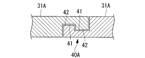
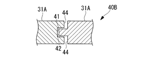
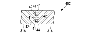
- 5A to 5D show structural examples of the concave and convex engaging portions
- FIGS. 5A and 5B are structural examples in which the upper and lower surfaces are engaged with each other at the ends of the adjacent divided platens
- FIG. 5C and FIG. 5D is a structural example in which end faces of adjacent divided platens are engaged with each other.
- the concavo-convex engaging portion 40 shown in FIG. 5A is the DD cross section of FIG. 4, the upper and lower surfaces of the adjacent divided platens 31A, 31A are engaged with each other so as to be overlapped from above and below.
- a concave portion 41 and a convex portion 42 are provided.
- the concave and convex portions 41 and 42 are formed by providing stepped surfaces 43 at the end portions of the divided platens 31A and 31A to form opposing concave and convex portions 41 and 42, and are connected by engaging the concave and convex portions 41 and 42 with each other.
- the front and back surfaces of the platen 30 having a disk shape are both flat and do not cause horizontal movement (displacement).
- the concavo-convex portions 41 and 42 may be formed one by one near the center of the step surface 43, or the concavo-convex portions formed at the end portions of each other like the concavo-convex engaging portion 40A shown in FIG. 5B. There is no particular limitation such as one that engages the portions 41 and 42.
- the concave and convex engaging portions 40B and 40C provided with one or a plurality of concave and convex portions 45 and 46 that engage with the end surfaces 44 of the adjacent divided platens 31A and 31A from the horizontal direction may be used.
- the concave and convex portions 45 and 46 are engaged by sliding in the horizontal direction from the side surface, and no vertical movement occurs in the engaged state.
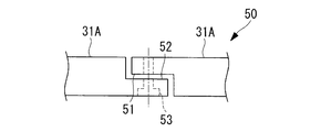
- the fastening connection portion 50 shown in FIG. 6A has a structure in which stepped surfaces 51 and 52 are formed at end portions of adjacent divided platens 31A and 31A, respectively, and are mechanically coupled using bolts 53 of fastening members.
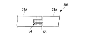
- the fastening connection portion 50A shown in FIG. 6B has a concave and convex engaging portion 54 formed at the end of the adjacent divided platens 31A and 31A, and uses a through bolt 55 of a fastening member that penetrates the concave and convex engaging portion 54. It is a mechanically coupled structure. If such fastening connection portions 50 and 50A are employed, mechanical connection by a fastening member is made, so that the division platen 31A can be positioned and integrated by reliable connection.
- a platen 10A shown in FIG. 7 is obtained by integrating and dividing the divided platen 11A of the platen 10 shown in FIG.
- a continuous ring-shaped plate material is used as the plate-shaped member 60 in accordance with, for example, the donut disk shape of the platen 10A.
- the plate-like member 60 described above is connected to the divided platen 11 ⁇ / b> A and the concave / convex engaging portion 62 in the plate connecting portion 61.
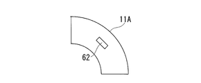
- the concave / convex engaging portion 62 is formed by providing concave and convex portions that engage with each other on the contact surfaces of the plate-like member 60 and the divided platen 11 ⁇ / b> A.
- the concave portion of the concave and convex engaging portion 62 may be provided on the plate-like member 60 and the convex portion may be provided on the divided platen 11A, or vice versa. Further, for example, as shown in FIG.
- a pair of concave and convex engaging portions 62 may be provided near both end portions of the divided platen 11A, or, for example, as shown in FIG. 8C, the central portion of the divided platen 11A. One place may be provided in the vicinity.
- the plate-like member 60 described above may be positioned and connected between the divided platen 11A and the plate-like member 60 using a fastening member such as a bolt as shown in FIGS. 9A and 9B, for example.
- a fastening member such as a bolt as shown in FIGS. 9A and 9B, for example.
- the divided platen 11A and the plate-like member 60 are fastened with the bolts 63 in the vertical direction.
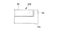
- a plate-like member 60 are fastened by a horizontal bolt 64.
- the platens 10, 20, and 30 are divided into a plurality of adjacent platens 11A, 21A, and 31A, the inner rings 22, 32, and the outer ring 33 between the concave and convex engaging portions.
- 40, the fastening connection part 50, and the plate connection part 61 may be provided.
- a platen that connects and integrates a plurality of divided platens can have a connection structure in which the concave and convex engaging portion 40, the fastening connection portion 50, and the plate connection portion 61 are appropriately combined, and the divided platen can be obtained by optimizing the connection structure. Positioning and connection between them can be easily performed.
- the divided platens 10, 20, and 30 that are divided into a plurality of circumferential directions from the disc integrated shape, and Therefore, the following effects can be obtained.
- the deformation (flexure) of the platen is less likely to occur during vulcanization of the tire, and the life of the heat generating part and the mounting member (for example, the flange part, upper and lower plates and fastening members such as bolts) and the like is improved.
- the platen that is not easily deformed is less likely to reduce the contact area with the heat generating portion, the heat transfer performance is not lowered, and good heating efficiency is obtained and the thermal life is improved.
- the platen can be partially exchanged for each divided platen, it is effective for cost reduction.
- the platen it becomes possible to select an optimal division shape according to the structure of the tire vulcanizer, the mold structure of the container, and the heating specification.
- a combination of different types of electric heating methods such as an electric heater (including a combination of rod and surface) or induction heating, or an electric heating method and a heating medium heating method. Easy to combine. For this reason, the tire heating temperature can be made uniform and optimized, and a high-quality tire can be manufactured by reducing the heating running cost and improving the control accuracy of the heating temperature.
- the tire vulcanizing apparatus 1 can solve the problems related to deformation and platen replacement at the time of tire vulcanization of the electrically heated platen.
- this invention is not limited to embodiment mentioned above, In the range which does not deviate from the summary, it can change suitably.
Landscapes
- Engineering & Computer Science (AREA)
- Mechanical Engineering (AREA)
- Physics & Mathematics (AREA)
- Health & Medical Sciences (AREA)
- Oral & Maxillofacial Surgery (AREA)
- Thermal Sciences (AREA)
- Heating, Cooling, Or Curing Plastics Or The Like In General (AREA)
- Moulds For Moulding Plastics Or The Like (AREA)
Abstract
Description
なお、従来のタイヤ加硫装置において、生タイヤの内部空間については、加熱媒体として蒸気が供給・循環されるとともに、窒素ガスや温水等の加熱、加圧媒体が密封されるようになっている。
電気式プラテンに適用される電気式加熱としては、プラテンに埋設した棒状または面状の電気ヒータ(たとえば、下記の特許文献3を参照)による加熱や、電磁コイルによる誘導加熱(たとえば、下記の特許文献4を参照)が知られている。
本発明は、上記の事情に鑑みてなされたものであり、その目的とするところは、電気加熱式プラテンが有するタイヤ加硫時の変形やプラテン交換に関する問題を解決したタイヤ加硫装置を提供することにある。
本発明に係るタイヤ加硫装置は、外金型内に収容された生タイヤを、当該生タイヤの外側及び内側から加熱して加硫成形するタイヤ加硫装置であって、前記生タイヤを充填するコンテナの上下に接して、または前記コンテナの上下部分に内蔵した状態に配設され、加硫時に前記外金型の外側から前記生タイヤを加熱するプラテンを電気式とし、ドーナツ型円盤とした前記プラテンの周方向が複数に分割されていることを特徴とするものである。
また、上記発明のタイヤ加硫装置において、前記プラテンは、複数に分割されて隣接する分割プラテン間が締結部材により接続及び位置決めされる締結接続部を備えたものでもよい。
また、上記発明のタイヤ加硫装置において、前記プラテンは、複数に分割されて隣接する分割プラテン間が板状部材を介して互いに接続及び位置決めされるプレート接続部を備えた構成でもよい。
上述した凹凸係合部、締結接続部、プレート接続部及びこれらの組み合わせにより、分割プラテン間の位置決め及び接続を容易に実施することができる。
そして、電気加熱式プラテンを複数に分割した構造は、加硫機の構造、タイヤ金型及び加熱仕様に合わせて最適な分割形状の選択が可能になるため、装置設計上の自由度向上に有効である。すなわち、棒状ヒータや面状ヒータを組み合わせた電気式加熱が容易になるだけでなく、電気式加熱と熱媒体式加熱との組合せも容易になるため、タイヤ加熱温度の均一化や最適化が可能となり、加熱ランニングコストの低減及び加熱温度のコントロール精度向上により、高品質のタイヤ製造が可能なタイヤ加硫装置となる。
図2に示すタイヤ加硫機1は、コンテナ(金型)2の内部で生タイヤTを加熱して加硫成形する装置である。コンテナ2は、内部に生タイヤTを充填する外金型(モールド)3と、タイヤの内部空間を形成するプラダ4とを具備して構成される。
なお、上述した外金型3は、生タイヤTの充填や加硫後のタイヤ取り出しを可能にするため、複数部材に分割されている。
図1Aに示すプラテン10のドーナツ型円盤形状は、本体11を円形とし、その中心部に同心円の貫通孔13を設けたものである。そして、プラテン10の本体11は、周方向が90度ピッチに4分割されている。
また、図中の符号14は、プラテン10をコンテナ2に接続するための鍔部であり、図示の構成例では、4分割した分割プラテン11A毎に設けられている。このような鍔部14を設けることにより、分割プラテン11Aを一体に接続して形成されるプラテン10の貫通孔13により、外金型3の設置位置が芯出しされる分割プラテン11Aの位置決め精度はより一層向上する。
なお、プラテン10の周方向分割数については、上述した4分割に限定されることはなく、2分割や3分割は勿論のこと、加硫するタイヤサイズ等に応じて5分割以上の複数に分割してもよい。
この場合、最も内側については、すなわち、貫通孔13が形成される中心部側については、周方向を連結してドーナツ型とすることが望ましい。
図5Aから図5Dは、凹凸係合部の構造例を示しており、図5A及び図5Bは隣接する分割プラテンの端部で上下面を重ね合わせて係合させた構造例、図5C及び図5Dは隣接する分割プラテンの端面どうしを係合させた構造例である。
上述したように、凹凸部41,42は段差面43の中央付近に1箇所ずつ形成してもよいし、あるいは図5Bに示す凹凸係合部40Aのように、互いの端部に形成した凹凸部41,42を係合させるものなど、特に限定されることはない。
図6Aに示す締結接続部50は、隣接する分割プラテン31A,31Aの端部に各々段差面51,52を形成し、締結部材のボルト53を用いて機械的に結合する構造である。また、図6Bに示す締結接続部50Aは、隣接する分割プラテン31A,31Aの端部に凹凸係合部54を形成し、この凹凸係合部54を貫通する締結部材の通しボルト55を用いて機械的に結合する構造である。
このような締結接続部50,50Aを採用すれば、締結部材による機械的な接続がなされるので、分割プラテン31Aを位置決めして確実な接続による一体化が可能になる。
図7に示すプラテン10Aは、図1Bに示すプラテン10の分割プラテン11Aが、板上部材60により接続及び位置決めされて一体化したものである。この場合、板状部材60は、たとえばプラテン10Aのドーナツ型円盤形状に合わせ、連続するリング形状の板材が使用される。
また、凹凸係合部62の位置は、たとえば図8Bに示すように、分割プラテン11Aの両端部付近に一対設けてもよいし、あるいは、たとえば図8Cに示すように、分割プラテン11Aの中心部付近に一箇所設けてもよい。
図9Aに示すプレート接続部61の構造例では、分割プラテン11Aと板状部材60との間が上下方向のボルト63で締結され、図9Bに示すプレート接続部61Bの構造例では、分割プラテン11Aと板状部材60との間が水平方向のボルト64で締結されている。
1)タイヤ加硫時にプラテンの変形(撓み)が発生しにくくなり、発熱部や取付部材(たとえば鍔部、上下プレートとボルト等の締結部材)等の寿命が向上する。
2)変形しにくいプラテンは、発熱部との接触面積が減少しにくくなるため、熱伝達性能の低下がなくなり、良好な加熱効率が得られるとともに熱寿命が向上する。
3)プラテンを交換する場合、取り外しや取り付けの調整が容易になるため、メンテナンス性が向上する。
4)プラテンは、分割プラテン毎の部分的な交換が可能になるので、コスト低減に有効である。
5)プラテンは、タイヤ加硫装置の構造、コンテナの金型構造及び加熱仕様に合わせた最適な分割形状を選択可能になる。
6)プラテンは、分割プラテン毎に、電気ヒータ(棒状及び面状の組合せを含む)や誘導加熱のように電気式加熱方式の種類が異なる組合せや、電気式加熱方式と熱媒体加熱方式との組合せが容易になる。このため、タイヤ加熱温度の均一化や最適化が可能となり、加熱ランニングコストの低減、加熱温度のコントロール精度向上により、高品質のタイヤ製造が可能となる。
なお、本発明は上述した実施形態に限定されることはなく、その要旨を逸脱しない範囲内において適宜変更することができる。
2 コンテナ(金型)
3 外金型(モールド)
4 プラダ
10,20,30 プラテン
11A,21A,31A 分割プラテン
12 発熱体
13 貫通孔
14 鍔部
40 凹凸係合部
50 締結接続部
60 板状部材
61 プレート接続部
Claims (8)
- 外金型内に収容された生タイヤを、当該生タイヤの外側及び内側から加熱して加硫成形するタイヤ加硫装置であって、
前記生タイヤを充填するコンテナの上下に接して、または前記コンテナの上下部分に内蔵した状態に配設され、加硫時に前記外金型の外側から前記生タイヤを加熱するプラテンを電気式とし、ドーナツ型円盤とした前記プラテンの周方向が複数に分割されているタイヤ加硫装置。 - 前記プラテンの半径方向が複数に分割されるとともに、最も内側の周方向を連結してドーナツ型円盤にした請求項1に記載のタイヤ加硫装置。
- 前記プラテンは、複数に分割されて隣接する分割プラテン間が互いの凹凸部を係合させて接続及び位置決めされる凹凸係合部を備えている請求項1または2に記載のタイヤ加硫装置。
- 前記プラテンは、複数に分割されて隣接する分割プラテン間が締結部材により接続及び位置決めされる締結接続部を備えている請求項1または2に記載のタイヤ加硫装置。
- 前記プラテンは、複数に分割されて隣接する分割プラテン間が板状部材を介して互いに接続及び位置決めされるプレート接続部を備えている請求項1または2に記載のタイヤ加硫装置。
- 前記プラテンは、複数に分割されて隣接する分割プラテン間が、前記凹凸係合部、前記締結接続部及び前記プレート接続部の二つ以上を備えている請求項1または2に記載のタイヤ加硫装置。
- 前記プレート接続部は、前記プラテンの上面または下面に設けた凹凸部と、前記板状部材の下面または上面に設けた凹凸部とを係合させて接続及び位置決めされる請求項5または6に記載のタイヤ加硫装置。
- 前記プレート接続部は、前記分割プラテンと前記板状部材との間が締結部材を介して接続及び位置決めされている請求項5または6に記載のタイヤ加硫装置。
Priority Applications (5)
| Application Number | Priority Date | Filing Date | Title |
|---|---|---|---|
| CN201180003486.9A CN102869486B (zh) | 2011-02-25 | 2011-05-10 | 轮胎硫化装置 |
| HRP20170048TT HRP20170048T1 (hr) | 2011-02-25 | 2011-05-10 | Uređaj za vulkanizaciju guma |
| US13/391,612 US8591212B2 (en) | 2011-02-25 | 2011-05-10 | Tire vulcanizer |
| KR1020127004462A KR101356815B1 (ko) | 2011-02-25 | 2011-05-10 | 타이어 가류 장치 |
| EP11817288.1A EP2679367B1 (en) | 2011-02-25 | 2011-05-10 | Tire vulcanization device |
Applications Claiming Priority (2)
| Application Number | Priority Date | Filing Date | Title |
|---|---|---|---|
| JP2011040720A JP5725906B2 (ja) | 2011-02-25 | 2011-02-25 | タイヤ加硫装置 |
| JP2011-040720 | 2011-02-25 |
Publications (1)
| Publication Number | Publication Date |
|---|---|
| WO2012114542A1 true WO2012114542A1 (ja) | 2012-08-30 |
Family
ID=46720353
Family Applications (1)
| Application Number | Title | Priority Date | Filing Date |
|---|---|---|---|
| PCT/JP2011/060741 Ceased WO2012114542A1 (ja) | 2011-02-25 | 2011-05-10 | タイヤ加硫装置 |
Country Status (8)
| Country | Link |
|---|---|
| US (1) | US8591212B2 (ja) |
| EP (1) | EP2679367B1 (ja) |
| JP (1) | JP5725906B2 (ja) |
| KR (1) | KR101356815B1 (ja) |
| CN (1) | CN102869486B (ja) |
| HR (1) | HRP20170048T1 (ja) |
| TW (1) | TWI428227B (ja) |
| WO (1) | WO2012114542A1 (ja) |
Families Citing this family (4)
| Publication number | Priority date | Publication date | Assignee | Title |
|---|---|---|---|---|
| JP2015020331A (ja) | 2013-07-18 | 2015-02-02 | 株式会社ジェイテクト | ゴムの加硫装置および加硫方法 |
| US9452579B2 (en) * | 2014-02-07 | 2016-09-27 | Mitsubishi Heavy Industries Machinery Technology Corporation | Mold heating device and tire vulcanizer |
| DE102023209752A1 (de) * | 2023-10-05 | 2025-04-10 | Continental Reifen Deutschland Gmbh | Heizpresse |
| CN117359846A (zh) * | 2023-11-27 | 2024-01-09 | 山东驰骋凯旋科技有限公司 | 一种便于组装的轮胎硫化机电磁加热装置 |
Citations (6)
| Publication number | Priority date | Publication date | Assignee | Title |
|---|---|---|---|---|
| JPH0180306U (ja) * | 1988-11-17 | 1989-05-30 | ||
| JPH05200754A (ja) | 1992-01-24 | 1993-08-10 | Mitsubishi Heavy Ind Ltd | タイヤ加硫プレス |
| JPH08174554A (ja) | 1994-12-20 | 1996-07-09 | Sumitomo Rubber Ind Ltd | タイヤ加硫用金型装置 |
| JPH08238626A (ja) | 1995-03-07 | 1996-09-17 | Mitsubishi Heavy Ind Ltd | タイヤ加硫用金型組立体 |
| JP2002036243A (ja) | 2000-07-31 | 2002-02-05 | Kobe Steel Ltd | 加硫機および加硫システム |
| JP2008100513A (ja) | 2006-09-21 | 2008-05-01 | Kobe Steel Ltd | 加熱ユニット、タイヤ加熱装置及びタイヤ金型の改造方法 |
Family Cites Families (10)
| Publication number | Priority date | Publication date | Assignee | Title |
|---|---|---|---|---|
| US1682620A (en) * | 1922-01-10 | 1928-08-28 | Budd Edward G Mfg Co | Apparatus for electrical vulcanizing |
| US2024554A (en) * | 1933-01-03 | 1935-12-17 | Vogt Leslie Thomas | Apparatus for vulcanizing tires and other articles |
| US2456063A (en) * | 1944-07-24 | 1948-12-14 | Harold V James | Tire retreading device |
| IT1189673B (it) * | 1986-05-20 | 1988-02-04 | Firestone Int Dev Spa | Impianto di vulcanizzazione di pneumatici |
| IT1257245B (it) * | 1992-07-01 | 1996-01-10 | Firestone Int Dev Spa | Reattore di vulcanizzazione per pneumatici di veicoli stradali. |
| JP2001079851A (ja) * | 1999-09-17 | 2001-03-27 | Kobe Steel Ltd | 加硫機 |
| CN100513115C (zh) * | 2005-03-26 | 2009-07-15 | 桂林橡胶机械厂 | 硫化机电加热装置 |
| CN101100094A (zh) * | 2006-07-05 | 2008-01-09 | 天津市橡塑机械研究所有限公司 | 巨型工程轮胎液压罐式硫化装置 |
| CN101511557B (zh) * | 2006-09-21 | 2011-09-07 | 株式会社神户制钢所 | 加热单元、轮胎加热装置及轮胎模具的改造方法 |
| JP5362263B2 (ja) * | 2008-06-20 | 2013-12-11 | 住友ゴム工業株式会社 | タイヤ加硫装置 |
-
2011
- 2011-02-25 JP JP2011040720A patent/JP5725906B2/ja active Active
- 2011-05-10 CN CN201180003486.9A patent/CN102869486B/zh not_active Expired - Fee Related
- 2011-05-10 HR HRP20170048TT patent/HRP20170048T1/hr unknown
- 2011-05-10 EP EP11817288.1A patent/EP2679367B1/en not_active Not-in-force
- 2011-05-10 US US13/391,612 patent/US8591212B2/en not_active Expired - Fee Related
- 2011-05-10 WO PCT/JP2011/060741 patent/WO2012114542A1/ja not_active Ceased
- 2011-05-10 KR KR1020127004462A patent/KR101356815B1/ko not_active Expired - Fee Related
- 2011-06-28 TW TW100122611A patent/TWI428227B/zh not_active IP Right Cessation
Patent Citations (6)
| Publication number | Priority date | Publication date | Assignee | Title |
|---|---|---|---|---|
| JPH0180306U (ja) * | 1988-11-17 | 1989-05-30 | ||
| JPH05200754A (ja) | 1992-01-24 | 1993-08-10 | Mitsubishi Heavy Ind Ltd | タイヤ加硫プレス |
| JPH08174554A (ja) | 1994-12-20 | 1996-07-09 | Sumitomo Rubber Ind Ltd | タイヤ加硫用金型装置 |
| JPH08238626A (ja) | 1995-03-07 | 1996-09-17 | Mitsubishi Heavy Ind Ltd | タイヤ加硫用金型組立体 |
| JP2002036243A (ja) | 2000-07-31 | 2002-02-05 | Kobe Steel Ltd | 加硫機および加硫システム |
| JP2008100513A (ja) | 2006-09-21 | 2008-05-01 | Kobe Steel Ltd | 加熱ユニット、タイヤ加熱装置及びタイヤ金型の改造方法 |
Non-Patent Citations (1)
| Title |
|---|
| See also references of EP2679367A4 |
Also Published As
| Publication number | Publication date |
|---|---|
| TWI428227B (zh) | 2014-03-01 |
| JP5725906B2 (ja) | 2015-05-27 |
| HRP20170048T1 (hr) | 2017-03-10 |
| CN102869486B (zh) | 2015-06-17 |
| KR20120139658A (ko) | 2012-12-27 |
| EP2679367A4 (en) | 2014-02-19 |
| CN102869486A (zh) | 2013-01-09 |
| EP2679367A1 (en) | 2014-01-01 |
| KR101356815B1 (ko) | 2014-01-28 |
| JP2012176552A (ja) | 2012-09-13 |
| US20130017287A1 (en) | 2013-01-17 |
| TW201235182A (en) | 2012-09-01 |
| US8591212B2 (en) | 2013-11-26 |
| EP2679367B1 (en) | 2016-10-19 |
Similar Documents
| Publication | Publication Date | Title |
|---|---|---|
| EP2960031B1 (en) | Method for producing a tire-vulcanizing mold and tire-vulcanizing mold | |
| JP5725906B2 (ja) | タイヤ加硫装置 | |
| JP6123753B2 (ja) | ゴムパッキンの成形・加硫用電磁誘導加熱式金型装置 | |
| JPWO2015118655A1 (ja) | 金型加熱装置、タイヤ加硫機 | |
| CN101462318A (zh) | 轮胎模具 | |
| JP5607432B2 (ja) | ゴム成形体の製造方法及びトランスファー成形用金型 | |
| US9796149B2 (en) | Mold with sectors for a tire including insulating supporting plates, and associated molding method | |
| JP5492149B2 (ja) | 剛性中子、及びそれを用いたタイヤの製造方法 | |
| KR101581940B1 (ko) | 냉각성능이 향상된 핫스템핑 금형 | |
| JPWO2018029726A1 (ja) | タイヤ加硫装置 | |
| JP2018519184A (ja) | 加工空間の高さ位置固定機 | |
| CN121548493A (zh) | 用于轮胎的固化模具 | |
| KR101796030B1 (ko) | 타이어 패턴 형성 불량방지용 가압장치 | |
| CN104290224A (zh) | 橡胶的硫化装置以及硫化方法 | |
| CN113815157B (zh) | 一种橡胶轮胎一体成型的电加热模具 | |
| KR102523200B1 (ko) | 유니포미티 특성을 확보한 타이어의 제조방법 및 그 타이어 | |
| JP5512451B2 (ja) | 台タイヤの加硫成型装置 | |
| JP7207005B2 (ja) | タイヤ加硫機 | |
| CN214820108U (zh) | 一种轮胎硫化环片模具 | |
| CN106660283A (zh) | 具有最佳闭合的轮胎硫化模具 | |
| JP2017217781A (ja) | タイヤ加硫用コンテナ | |
| JP2003170440A (ja) | 滑り支承部材の製造方法 | |
| CN108237176A (zh) | 一种核聚变真空室壳体冷成型模具 | |
| KR20250072246A (ko) | 타이어 성형 금형 장치, 이를 포함하는 타이어 가류 몰드 시스템 및 이를 제조하는 제조 방법 | |
| JP2025054585A (ja) | タイヤ加硫装置 |
Legal Events
| Date | Code | Title | Description |
|---|---|---|---|
| WWE | Wipo information: entry into national phase |
Ref document number: 201180003486.9 Country of ref document: CN |
|
| ENP | Entry into the national phase |
Ref document number: 20127004462 Country of ref document: KR Kind code of ref document: A |
|
| REEP | Request for entry into the european phase |
Ref document number: 2011817288 Country of ref document: EP |
|
| WWE | Wipo information: entry into national phase |
Ref document number: 13391612 Country of ref document: US Ref document number: 432/MUMNP/2012 Country of ref document: IN Ref document number: 2011817288 Country of ref document: EP |
|
| 121 | Ep: the epo has been informed by wipo that ep was designated in this application |
Ref document number: 11817288 Country of ref document: EP Kind code of ref document: A1 |
|
| NENP | Non-entry into the national phase |
Ref country code: DE |