WO2012114570A1 - フィラメントワインディング装置 - Google Patents
フィラメントワインディング装置 Download PDFInfo
- Publication number
- WO2012114570A1 WO2012114570A1 PCT/JP2011/071627 JP2011071627W WO2012114570A1 WO 2012114570 A1 WO2012114570 A1 WO 2012114570A1 JP 2011071627 W JP2011071627 W JP 2011071627W WO 2012114570 A1 WO2012114570 A1 WO 2012114570A1
- Authority
- WO
- WIPO (PCT)
- Prior art keywords
- winding
- fiber layer
- end position
- liner
- fiber bundle
- Prior art date
- Legal status (The legal status is an assumption and is not a legal conclusion. Google has not performed a legal analysis and makes no representation as to the accuracy of the status listed.)
- Ceased
Links
Images

Classifications
-
- B—PERFORMING OPERATIONS; TRANSPORTING
- B29—WORKING OF PLASTICS; WORKING OF SUBSTANCES IN A PLASTIC STATE IN GENERAL
- B29C—SHAPING OR JOINING OF PLASTICS; SHAPING OF MATERIAL IN A PLASTIC STATE, NOT OTHERWISE PROVIDED FOR; AFTER-TREATMENT OF THE SHAPED PRODUCTS, e.g. REPAIRING
- B29C70/00—Shaping composites, i.e. plastics material comprising reinforcements, fillers or preformed parts, e.g. inserts
- B29C70/04—Shaping composites, i.e. plastics material comprising reinforcements, fillers or preformed parts, e.g. inserts comprising reinforcements only, e.g. self-reinforcing plastics
- B29C70/06—Fibrous reinforcements only
- B29C70/10—Fibrous reinforcements only characterised by the structure of fibrous reinforcements, e.g. hollow fibres
- B29C70/16—Fibrous reinforcements only characterised by the structure of fibrous reinforcements, e.g. hollow fibres using fibres of substantial or continuous length
-
- B—PERFORMING OPERATIONS; TRANSPORTING
- B65—CONVEYING; PACKING; STORING; HANDLING THIN OR FILAMENTARY MATERIAL
- B65H—HANDLING THIN OR FILAMENTARY MATERIAL, e.g. SHEETS, WEBS, CABLES
- B65H54/00—Winding, coiling, or depositing filamentary material
-
- B—PERFORMING OPERATIONS; TRANSPORTING
- B29—WORKING OF PLASTICS; WORKING OF SUBSTANCES IN A PLASTIC STATE IN GENERAL
- B29C—SHAPING OR JOINING OF PLASTICS; SHAPING OF MATERIAL IN A PLASTIC STATE, NOT OTHERWISE PROVIDED FOR; AFTER-TREATMENT OF THE SHAPED PRODUCTS, e.g. REPAIRING
- B29C53/00—Shaping by bending, folding, twisting, straightening or flattening; Apparatus therefor
- B29C53/56—Winding and joining, e.g. winding spirally
- B29C53/58—Winding and joining, e.g. winding spirally helically
- B29C53/60—Winding and joining, e.g. winding spirally helically using internal forming surfaces, e.g. mandrels
- B29C53/602—Winding and joining, e.g. winding spirally helically using internal forming surfaces, e.g. mandrels for tubular articles having closed or nearly closed ends, e.g. vessels, tanks, containers
-
- B—PERFORMING OPERATIONS; TRANSPORTING
- B29—WORKING OF PLASTICS; WORKING OF SUBSTANCES IN A PLASTIC STATE IN GENERAL
- B29C—SHAPING OR JOINING OF PLASTICS; SHAPING OF MATERIAL IN A PLASTIC STATE, NOT OTHERWISE PROVIDED FOR; AFTER-TREATMENT OF THE SHAPED PRODUCTS, e.g. REPAIRING
- B29C53/00—Shaping by bending, folding, twisting, straightening or flattening; Apparatus therefor
- B29C53/80—Component parts, details or accessories; Auxiliary operations
- B29C53/8008—Component parts, details or accessories; Auxiliary operations specially adapted for winding and joining
- B29C53/8041—Measuring, controlling or regulating
-
- B—PERFORMING OPERATIONS; TRANSPORTING
- B29—WORKING OF PLASTICS; WORKING OF SUBSTANCES IN A PLASTIC STATE IN GENERAL
- B29C—SHAPING OR JOINING OF PLASTICS; SHAPING OF MATERIAL IN A PLASTIC STATE, NOT OTHERWISE PROVIDED FOR; AFTER-TREATMENT OF THE SHAPED PRODUCTS, e.g. REPAIRING
- B29C70/00—Shaping composites, i.e. plastics material comprising reinforcements, fillers or preformed parts, e.g. inserts
- B29C70/04—Shaping composites, i.e. plastics material comprising reinforcements, fillers or preformed parts, e.g. inserts comprising reinforcements only, e.g. self-reinforcing plastics
- B29C70/28—Shaping operations therefor
- B29C70/30—Shaping by lay-up, i.e. applying fibres, tape or broadsheet on a mould, former or core; Shaping by spray-up, i.e. spraying of fibres on a mould, former or core
- B29C70/38—Automated lay-up, e.g. using robots, laying filaments according to predetermined patterns
- B29C70/382—Automated fiber placement [AFP]
-
- B—PERFORMING OPERATIONS; TRANSPORTING
- B29—WORKING OF PLASTICS; WORKING OF SUBSTANCES IN A PLASTIC STATE IN GENERAL
- B29C—SHAPING OR JOINING OF PLASTICS; SHAPING OF MATERIAL IN A PLASTIC STATE, NOT OTHERWISE PROVIDED FOR; AFTER-TREATMENT OF THE SHAPED PRODUCTS, e.g. REPAIRING
- B29C63/00—Lining or sheathing, i.e. applying preformed layers or sheathings of plastics; Apparatus therefor
- B29C63/24—Lining or sheathing, i.e. applying preformed layers or sheathings of plastics; Apparatus therefor using threads
-
- B—PERFORMING OPERATIONS; TRANSPORTING
- B29—WORKING OF PLASTICS; WORKING OF SUBSTANCES IN A PLASTIC STATE IN GENERAL
- B29C—SHAPING OR JOINING OF PLASTICS; SHAPING OF MATERIAL IN A PLASTIC STATE, NOT OTHERWISE PROVIDED FOR; AFTER-TREATMENT OF THE SHAPED PRODUCTS, e.g. REPAIRING
- B29C70/00—Shaping composites, i.e. plastics material comprising reinforcements, fillers or preformed parts, e.g. inserts
- B29C70/04—Shaping composites, i.e. plastics material comprising reinforcements, fillers or preformed parts, e.g. inserts comprising reinforcements only, e.g. self-reinforcing plastics
- B29C70/28—Shaping operations therefor
- B29C70/30—Shaping by lay-up, i.e. applying fibres, tape or broadsheet on a mould, former or core; Shaping by spray-up, i.e. spraying of fibres on a mould, former or core
- B29C70/32—Shaping by lay-up, i.e. applying fibres, tape or broadsheet on a mould, former or core; Shaping by spray-up, i.e. spraying of fibres on a mould, former or core on a rotating mould, former or core
Definitions
- the present invention relates to the technology of a filament winding apparatus.
- the filament winding apparatus includes a control unit that controls the operation of winding the fiber bundle around the liner.
- the control unit stores a series of operations for winding the fiber bundle around the liner as winding data including a plurality of steps, and controls the operation for winding the fiber bundle based on the winding data.
- the controller is provided with a motion controller, and the motion controller creates a control signal for each process based on the winding data, thereby realizing a series of operations for winding the fiber bundle.
- the end positions of the dome portions at both ends of the liner are determined for each fiber layer by design.
- the end position of the fiber layer means the position of the fiber bundle on the smallest diameter side when the fiber bundle is wound around the dome part of the liner from the maximum diameter side to the minimum diameter side (the position of each fiber layer in the dome part). The lowest point). That is, the position of the end of the fiber layer in the dome portion of the liner is determined for each fiber layer so that the strength, dimensions, etc. of the finished product satisfy the predetermined conditions. For this reason, the winding data memorize
- the end position of the fiber layer in the dome portion of the liner may not be as designed. This is often caused by the difference in the types of fiber bundles and the viscosity of the resin impregnated in the fiber bundles.
- the winding data is corrected by comparing the design value and the actual measurement value so that the end position of the fiber layer in the dome portion is as designed, and the winding data is recreated. It is done.
- the present invention has been made to solve such problems.
- the objective of this invention is providing the filament winding apparatus which correct
- the first invention is a filament winding apparatus for winding a fiber bundle around a liner surface, storing a series of operations for winding the fiber bundle around the liner as winding data comprising a plurality of steps, and the dome of the liner.
- a control unit for controlling.
- 2nd invention is 1st invention, Comprising:
- the said control part interrupts the said basic operation, when the process of winding a fiber bundle to the edge part position of a fiber layer is complete
- the third invention is either the first or second invention, further comprising a detection unit for detecting the end position of the fiber layer.
- the correction operation is based on an operation of detecting the end position of the fiber layer formed by the basic operation by the detection unit, an actual measurement value of the end position of the fiber layer, and a design value of the end position of the fiber layer. An operation of calculating a correction value and an operation of increasing or decreasing the winding of the fiber bundle based on the correction value.
- the 4th invention is 3rd invention, Comprising:
- the said control part performs operation
- movement which increases / decreases winding of a fiber bundle based on the said correction value among the said correction operations and the edge part position of the said fiber layer
- 5th invention is 4th invention, Comprising: When the said control part complete
- the basic operation of winding the fiber bundle based on the winding data, and the measured position and design of the end position of the fiber layer A correction operation is performed based on the value. For this reason, the end position of the fiber layer in the dome portion of the liner can be easily corrected.
- the basic operation is interrupted and the correction operation is interrupted when the step of winding the fiber bundle to the end position of the fiber layer is completed among the plurality of steps of the winding data. For this reason, the end position of the fiber layer in the dome portion of the liner can be easily corrected without correcting the winding data.
- the increase / decrease amount of the winding of the fiber bundle performed by the correction operation is stored as a true correction value. For this reason, an accurate correction value for correcting the end position of the fiber layer in the dome portion of the liner can be stored and used.
- the basic operation is interrupted when the step of winding the fiber bundle to the end position of the fiber layer is completed among the plurality of steps of the winding data, and the correction operation is performed based on the true correction value. Interrupt. For this reason, it is possible to quickly perform a correction operation based on an accurate correction value for correcting the end position of the fiber layer in the dome portion of the liner, thereby improving the production efficiency.
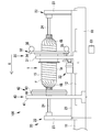
- the side view which shows the whole structure of a filament winding apparatus The side view which shows the whole structure of a filament winding apparatus.
- FW apparatus 100 A filament winding apparatus 100 (hereinafter referred to as “FW apparatus 100”) according to an embodiment of the present invention will be described.
- FIG. 1 shows the overall configuration of the FW device 100.
- An arrow X shown in the figure indicates the transfer direction of the liner 1.
- the direction parallel to the transfer direction of the liner 1 is defined as the front-rear direction of the FW device 100, the direction in which the liner 1 is transferred is defined as the front side (left side in the figure), and the opposite side of the front side is defined as the rear side (right side in the figure). Since the FW device 100 reciprocates the liner 1 in the front-rear direction, the front side and the rear side are determined according to the transfer direction of the liner 1.
- the FW device 100 is a device that forms a plurality of fiber layers by winding the fiber bundle F around the outer peripheral surface 1S of the liner 1.
- the FW device 100 mainly includes a main base 10, a liner transfer device 20, a hoop winding device 30, a helical winding device 40, and a control unit 51.
- the liner 1 is a substantially cylindrical hollow container formed of, for example, a high-strength aluminum material or a polyamide resin.
- the central portion of the liner 1 is a cylindrical portion 1A having a constant radius, and dome portions 1B are formed at both ends of the cylindrical portion 1A.
- the dome portion 1B has a dome shape with a radius decreasing toward the end side.
- the pressure resistance characteristics are improved by winding the fiber bundle F around the outer peripheral surface 1 ⁇ / b> S of the liner 1. That is, the liner 1 is a base material constituting the pressure vessel.
- the main base 10 is a main structure that forms the basis of the FW device 100.
- a liner transfer device rail 11 is provided on the upper portion of the main base 10.
- a liner transfer device 20 is placed on the liner transfer device rail 11.
- a hoop winding device rail 12 is provided on the upper portion of the main base 10 in parallel to the liner transfer device rail 11.
- a hoop winding device 30 is placed on the rail 12 for the hoop winding device.
- the main base 10 constitutes the basis of the FW device 100 and also allows the liner transfer device 20 and the hoop winding device 30 to move in the front-rear direction of the FW device 100.
- the liner transfer device 20 is a device that transfers the liner 1 while rotating it.
- the liner transfer device 20 rotates the liner 1 about the front-rear direction of the FW device 100 as a central axis, and transfers the liner 1 in the front-rear direction of the FW device 100.
- the liner transfer device 20 mainly includes a base 21 and a liner support portion 22.
- a pair of liner support portions 22 are provided on the upper portion of the base 21.
- the liner support portion 22 includes a liner support frame 23 and a rotating shaft 24.
- the liner support frame 23 extends upward from the base 21.
- the rotating shaft 24 extends from the liner support frame 23 in the front-rear direction.
- the liner 1 is attached to the rotating shaft 24 and rotated in one direction by a power mechanism (not shown).
- the liner transfer device 20 can rotate the liner 1 with the front-rear direction of the FW device 100 as a central axis, and can transfer the liner 1 in the front-rear direction of the FW device 100.
- the hoop winding device 30 is a device that forms a fiber layer by winding the fiber bundle F around the outer peripheral surface 1S of the liner 1.
- the hoop winding device 30 performs so-called hoop winding in which the winding angle of the fiber bundle F is substantially perpendicular to the front-rear direction of the FW device 100.
- the hoop winding device 30 mainly includes a base 31, a power mechanism 32, and a hoop winding device 33.
- the base 31 is provided with a hoop winding device 33 that is rotated by a power mechanism 32.
- the hoop winding device 33 includes a winding table 34 and a bobbin 35, and performs hoop winding on the outer peripheral surface 1 ⁇ / b> S of the liner 1.
- the winding table 34 mainly performs hoop winding.
- the bobbin 35 supplies the fiber bundle F to the winding table 34.
- the fiber bundle F is guided to the outer peripheral surface 1S of the liner 1 by a fiber bundle guide provided on the winding table 34, and the winding table 34 rotates to perform hoop winding.
- the hoop winding device 30 performs hoop winding, in which the winding angle of the fiber bundle F is substantially perpendicular to the front-rear direction of the FW device 100, mainly on the cylindrical portion 1A of the liner 1.
- the helical winding device 40 is a device that forms a fiber layer by winding the fiber bundle F around the outer peripheral surface 1S of the liner 1.
- the helical winding device 40 performs so-called helical winding in which the winding angle of the fiber bundle F is a predetermined value with respect to the front-rear direction of the FW device 100.
- the helical winding device 40 mainly includes a base 41 and a helical winding device 42.
- the base 41 is provided with a helical winding device 42.
- the helical winding device 42 includes a first helical head 43 and a second helical head 44, and performs helical winding on the outer peripheral surface 1 ⁇ / b> S of the liner 1.
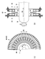
- a fiber bundle guide 45 (see FIG. 2) provided on the first helical head 43 and a fiber bundle guide 45 (see FIG. 2) provided on the second helical head 44 respectively cause a fiber bundle F on the outer peripheral surface 1S of the liner 1. Is guided, and helical winding is performed as the liner 1 passes while rotating.
- the helical winding device 40 performs helical winding with respect to the cylindrical portion 1A and the dome portion 1B of the liner 1 so that the winding angle of the fiber bundle F is a predetermined value with respect to the front-rear direction of the FW device 100. Do.
- the control unit 51 is a device for controlling a series of operations for winding the fiber bundle F around the outer peripheral surface 1S of the liner 1 by controlling the liner transfer device 20, the hoop winding device 30, the helical winding device 40, and the like.
- the control unit 51 includes a CPU as a calculation unit, a ROM, a RAM, a motion controller 52, and the like as storage units.
- the ROM of the control unit 51 stores control software that causes hardware such as a CPU included in the control unit 51 to operate as the control unit of the FW device 100.
- the control software sets a series of operations for winding the fiber bundle F around the liner 1 as winding data including a plurality of steps.
- the storage unit stores the winding data.
- the motion controller 52 creates a control signal based on the set winding data.
- the winding data is an operation diagram in which the operation of the motors 54A, 54B,.
- the series of operations for winding the fiber bundle F is, for example, that the liner transfer device 20 moves while rotating the liner 1, and the helical winding device 40 changes the phase of the fiber bundle guide 45 by rotating the second helical head 44.
- these are operations of winding the fiber bundle F while being related to each other.
- the operation of winding the fiber bundle F around the liner 1 by creating a control signal for each process based on the winding data set in advance is a basic operation.
- the end position of the fiber layer is detected, and the end position of the fiber layer is corrected based on the actual measurement value and the design value.
- This operation is referred to as a correction operation.
- the control unit 51 When forming the fiber layer by winding the fiber bundle F around the dome portion 1B of the liner 1, the control unit 51 not only controls the basic operation based on the winding data but also sets the end position of the fiber layer as the actual measurement value. A correction operation to be corrected based on the design value is controlled.
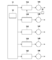
- FIG. 3 is a diagram illustrating a control system including the control unit 51.
- the control unit 51 is the core of the control system in the FW device 100.
- the control system of the FW device 100 mainly includes a control unit 51, motor drivers 53A, 53B,..., Motors 54A, 54B,.
- the control unit 51 creates a control signal based on the winding data. Specifically, the motion controller 52 of the control unit 51 creates a pulse signal having a number of pulses and a frequency according to each numerical value of the winding data, and the pulse signals are transmitted to the motors 54A and 54B via the motor drivers 53A, 53B. Output to.
- the motors 54A, 54B,... Are pulse input type stepping motors or servo motors.
- the motors 54A, 54B,... Convert the pulse input from the motor drivers 53A, 53B,.
- the detection unit 55 detects the end position of the fiber layer formed by the basic operation and the correction operation, creates a voltage signal corresponding to the end position of the fiber layer, and outputs the voltage signal to the control unit 51 ( (See FIG. 5).
- a camera may be used as the detection unit 55, and the end position of the fiber layer may be detected by processing the captured image.
- control unit 51 generates a control signal and drives the motors 54A, 54B,... Via the motor drivers 53A, 53B,.
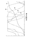
- FIG. 4 is a diagram illustrating an example of winding data representing a series of operations for winding the fiber bundle F.
- the horizontal axis of this figure has shown the process of a series of operation
- FIG. The vertical axis in this figure indicates the operation of the motors 54A, 54B,.
- the Nth step shown in FIG. 4 is a step of winding the fiber bundle to the end position of a certain fiber layer among the plurality of steps of the winding data.
- the winding data C1 represents the rotation operation of the liner 1.
- the control unit 51 creates a control signal based on the winding data C1, and drives the motor 54A of the power mechanism that constitutes the liner transfer device 20. Since the rotation direction of the liner 1 is always constant (see arrow D1 in FIG. 2B), the winding data C1 indicates a diverging operation in which the numerical value increases for each process.
- the winding data C2 represents the transfer operation of the liner 1.
- the control unit 51 creates a control signal based on the winding data C2, and drives the motor 54B of the power mechanism that constitutes the liner transfer device 20. Since the transfer direction of the liner 1 is changed to the front-rear direction (see arrow D2 in FIG. 2B), the winding data C2 indicates a repetitive operation that decreases again after the numerical value increases.
- the winding data C3 represents the expansion / contraction operation of the fiber bundle guide 45.
- the control unit 51 creates a control signal based on the winding data C3 and drives the motor 54C of the power mechanism that constitutes the helical winding device 40.
- the winding data C3 is again displayed after the numerical value increases. A decreasing repetitive motion is shown.
- the winding data C4 represents the rotation operation of the fiber bundle guide 45.
- the control unit 51 creates a control signal based on the winding data C4, and drives the motor 54D of the power mechanism that constitutes the helical winding device 40. Since the rotation direction of the fiber bundle guide 45 is changed to the normal rotation direction or the reverse rotation direction (see arrow D4 in FIG. 2A), the winding data C3 indicates a repetitive operation that decreases again after the numerical value increases. .
- the winding data C5 represents the rotation operation of the second helical head 44.
- the control unit 51 creates a control signal based on the winding data C5, and drives the motor 54E of the power mechanism that constitutes the helical winding device 40. Since the rotation direction of the second helical head 44 is changed to the normal rotation direction or the reverse rotation direction (see arrow D5 in FIG. 2A), the winding data C3 indicates a repetitive operation that decreases again after the numerical value increases. Yes.
- the Nth step shown in FIG. 4 is a step of winding the fiber bundle to the end position of a certain fiber layer among the plurality of steps of the winding data.
- 5A and 5B are diagrams illustrating a state in which the Nth step of the basic operation based on the winding data has been completed and the winding of the fiber bundle has reached the end position of the fiber layer in the dome portion.
- the end position of the actually formed fiber layer is a position indicated by a solid line.
- the design end position of the fiber layer is set to a position indicated by a two-dot chain line.
- the winding data is created with the goal that the end position of the fiber layer becomes as designed when the Nth step of the basic operation is completed.
- the end position of the fiber layer has not reached the design value when the Nth step of the basic operation is completed.
- the control unit 51 performs control to interrupt the basic operation and interrupt the correction operation when the Nth step of the winding data is completed. .
- FIG. 5 shows a case where the end position of the fiber layer has not reached the design value when the Nth step of the basic operation is completed. That is, this is a case where the actual winding is insufficient with respect to the design value.
- control for adding the winding amount is performed.
- the end position of the fiber layer may exceed the design value when the Nth step of the basic operation is completed. That is, the actual winding is excessive with respect to the design value.
- control for reducing the winding amount is performed.
- the detection unit 55 detects the end position of the fiber layer formed by the basic operation.
- the fiber layer is imaged from the axial direction of the liner 1 by the detection unit 55, and the measured value of the end position of the fiber layer is detected by processing the captured image. Yes.
- the control unit 51 calculates a correction value based on the actually measured value and the design value of the end position of the fiber layer.
- the correction value is the rotation direction and rotation angle of the liner 1.
- control of the transfer operation of the liner 1, the expansion / contraction operation of the fiber bundle guide 45, the rotation operation of the fiber bundle guide 45, and the rotation operation of the second helical head 44 is not performed. It is assumed that the correction operation is performed while maintaining the state at the time when the Nth step of the basic operation is completed.
- the rotation direction correction value is obtained when the measured value of the end position of the fiber layer is insufficient with respect to the design value, that is, (measured value R1 of the radius of the end position of the fiber layer). )-(Design value R2 of the radius of the end position of the fiber layer)> 0 (plus), the rotation direction is the direction in which the winding amount is added (forward rotation: direction D1 in FIG. 5A).
- the rotation direction is a direction in which the amount of winding is reduced (reverse rotation: the direction opposite to the D1 direction in FIG. 5A).
- the rotation angle correction value ⁇ 1 is R for the radius of the liner 1, R1 for the measured radius of the end position of the fiber layer, and R2 for the designed value of the radius of the end position of the fiber layer. Then, it is calculated by the following formula 1.
- the control unit 51 controls the driving of the motor 54A, and among the correction operations, an operation for increasing / decreasing the winding of the fiber bundle based on the correction value, and an operation for detecting the end position of the fiber layer by the detection unit Are controlled alternately.
- the liner rotation angle is the calculated correction value ⁇ 1 (100%), and the rotation direction is normal rotation.
- R1 If> R2, the operation of forwardly rotating the liner 1 with the correction value ⁇ 1 (100%) and the operation of detecting the end position of the fiber layer by the detection unit are alternately repeated until R1 ⁇ R2.
- the liner rotation angle is set to 25% of the correction value ⁇ 1, and the rotation direction is reversed.
- the operation of reversing the liner 1 at 25% of the correction value ⁇ 1 and the operation of detecting the end position of the fiber layer by the detection unit are alternately repeated until R1> R2.
- the liner rotation angle is set to 6% of the correction value ⁇ 1, and the rotation direction is set to normal rotation.
- the operation of rotating the liner 1 forward at 6% of the correction value ⁇ 1 and the operation of detecting the end position of the fiber layer by the detection unit are alternately repeated until R1 ⁇ R2.
- the correction operation is terminated at that time.
- the difference between the actually measured value and the design value of the end position of the fiber layer becomes 1.5% or less of the correction value ⁇ 1 as the rotation angle of the liner 1, the correction operation is terminated. .
- the control unit 51 resumes the basic operation from the (N + 1) th step of the winding data.
- control part 51 may memorize
- movement for example, “correction value ⁇ 1 (100%), normal rotation”, “correction value ⁇ 1 is 25%, reverse rotation”, “correction value ⁇ 1 is 6%, normal rotation”, and “correction value ⁇ 1 is 1”. Assuming that “.5%, reverse rotation” is performed once each, the true correction value ⁇ 2 is “79.5% of the correction value ⁇ 1” and the rotation direction is “forward rotation”.
- control unit 51 when the control unit 51 stores the true correction value as described above and then winds the fiber layer around the next liner 1 and winds the fiber layer, the control unit 51 performs the basic operation when the Nth step of the winding data is completed.
- the operation may be interrupted and a correction operation based on the true correction value may be interrupted.
- the FW device 100 according to the present embodiment described above has the following effects.
- the fiber bundle F When the fiber bundle F is wound around the dome portion 1B of the liner 1 to form the fiber layer, the basic operation of winding the fiber bundle F based on the winding data, the end position of the fiber layer based on the actual measurement value and the design value. Correction operation is performed. For this reason, the edge part position of the fiber layer in the dome part 1B of the liner 1 can be easily corrected.
- the correction value is calculated based on the operation of detecting the end position of the fiber layer formed by the basic operation by the detection unit 55, the measured value of the end position of the fiber layer, and the design value of the end position of the fiber layer.
- the operation and the operation of increasing / decreasing the winding of the fiber bundle F based on the correction value are performed. For this reason, the edge part position of the fiber layer in the dome part 1B of the liner 1 can be easily and automatically corrected.
- the amount of increase / decrease in winding of the fiber bundle F performed by the correction operation is stored as a true correction value. For this reason, an accurate correction value for correcting the end position of the fiber layer in the dome portion 1B of the liner 1 can be stored and used.
- the basic operation is interrupted when the process of winding the fiber bundle F to the end position of the fiber layer is completed among the plurality of processes of the winding data, and the correction operation is interrupted based on the true correction value. For this reason, it is possible to quickly perform a correction operation based on an accurate correction value for correcting the end position of the fiber layer in the dome portion 1B of the liner 1, thereby improving the production efficiency.
- the end position of the fiber layer formed by the basic operation is detected by the detection unit 55, but the operator manually measures the end position of the fiber layer, and the correction operation is performed based on the measured actual value. May be performed.
- the filament winding apparatus of the present invention is industrially useful because it can easily correct the end position of the fiber layer in the dome portion of the liner.
Landscapes
- Engineering & Computer Science (AREA)
- Mechanical Engineering (AREA)
- Chemical & Material Sciences (AREA)
- Composite Materials (AREA)
- Robotics (AREA)
- Textile Engineering (AREA)
- Moulding By Coating Moulds (AREA)
- Winding Filamentary Materials (AREA)
Abstract
Description

>R2のままであれば、R1<R2になるまで補正値θ1(100%)でライナー1を正転する動作、及び繊維層の端部位置を検出部により検出する動作を交互に繰り返す。
10 主基台
20 ライナー移送装置
30 フープ巻き装置
40 ヘリカル巻き装置
43 固定ヘリカルヘッド
44 可動ヘリカルヘッド
45 繊維束ガイド
51 制御部
52 モーションコントローラ
53A モータドライバ
54A モータ
55 検出部
F 繊維束
Claims (5)
- 繊維束をライナー表面に巻き付けるフィラメントワインディング装置であって、
ライナーに繊維束を巻き付けるための一連の動作を複数の工程からなる巻きデータとして記憶するとともに、前記ライナーのドーム部に繊維束を巻き付けて繊維層を形成する場合に、前記巻きデータに基づいて繊維束を巻き付ける基本動作と、繊維層の端部位置を実測値と設計値とに基づいて補正する補正動作と、を制御する制御部を備えたことを特徴とするフィラメントワインディング装置。 - 請求項1に記載のフィラメントワインディング装置であって、
前記制御部は、巻きデータの複数の工程のうち、繊維層の端部位置まで繊維束を巻き付ける工程を終了した時点で前記基本動作を中断し、前記補正動作を割り込ませることを特徴とするフィラメントワインディング装置。 - 請求項1又は2のいずれか1項に記載のフィラメントワインディング装置であって、
繊維層の端部位置を検出する検出部を更に備え、
前記補正動作は、
基本動作により形成された繊維層の端部位置を前記検出部により検出する動作と、
繊維層の端部位置の実測値と繊維層の端部位置の設計値とに基づいて補正値を算出する動作と、
前記補正値に基づいて繊維束の巻き付けの増減を行う動作と、
を含むことを特徴とするフィラメントワインディング装置。 - 請求項3に記載のフィラメントワインディング装置であって、
前記制御部は、前記補正動作のうち、前記補正値に基づいて繊維束の巻き付けの増減を行う動作と、繊維層の端部位置を前記検出部により検出する動作とを交互に行わせるように制御し、繊維層の端部位置の実測値と繊維層の端部位置の設計値との差異が所定値以下となった場合に、前記補正動作により行った繊維束の巻き付けの増減量を真の補正値として記憶することを特徴とするフィラメントワインディング装置。 - 請求項4に記載のフィラメントワインディング装置であって、
前記制御部は、巻きデータの複数の工程のうち、繊維層の端部位置まで繊維束を巻き付ける工程を終了した時点で前記基本動作を中断し、前記真の補正値に基づく前記補正動作を割り込ませることを特徴とするフィラメントワインディング装置。
Priority Applications (5)
| Application Number | Priority Date | Filing Date | Title |
|---|---|---|---|
| JP2013500827A JP5643419B2 (ja) | 2011-02-21 | 2011-09-22 | フィラメントワインディング装置 |
| EP11859020.7A EP2679381B1 (en) | 2011-02-21 | 2011-09-22 | Filament winding device |
| CN201180067460.0A CN103370184B (zh) | 2011-02-21 | 2011-09-22 | 长丝络纱装置 |
| KR1020137023691A KR101543679B1 (ko) | 2011-02-21 | 2011-09-22 | 필라멘트 와인딩 장치 |
| US13/985,972 US9102499B2 (en) | 2011-02-21 | 2011-09-22 | Filament winding device |
Applications Claiming Priority (2)
| Application Number | Priority Date | Filing Date | Title |
|---|---|---|---|
| JP2011034878 | 2011-02-21 | ||
| JP2011-034878 | 2011-02-21 |
Publications (1)
| Publication Number | Publication Date |
|---|---|
| WO2012114570A1 true WO2012114570A1 (ja) | 2012-08-30 |
Family
ID=46720374
Family Applications (1)
| Application Number | Title | Priority Date | Filing Date |
|---|---|---|---|
| PCT/JP2011/071627 Ceased WO2012114570A1 (ja) | 2011-02-21 | 2011-09-22 | フィラメントワインディング装置 |
Country Status (6)
| Country | Link |
|---|---|
| US (1) | US9102499B2 (ja) |
| EP (1) | EP2679381B1 (ja) |
| JP (1) | JP5643419B2 (ja) |
| KR (1) | KR101543679B1 (ja) |
| CN (1) | CN103370184B (ja) |
| WO (1) | WO2012114570A1 (ja) |
Cited By (6)
| Publication number | Priority date | Publication date | Assignee | Title |
|---|---|---|---|---|
| JP2013063585A (ja) * | 2011-09-16 | 2013-04-11 | Murata Machinery Ltd | フィラメントワインディング装置 |
| JP2014136369A (ja) * | 2013-01-17 | 2014-07-28 | Toyota Motor Corp | フィラメントワインディング方法とフィラメントワインディング装置 |
| JP2014200966A (ja) * | 2013-04-03 | 2014-10-27 | 村田機械株式会社 | フィラメントワインディング装置 |
| JP2015107574A (ja) * | 2013-12-04 | 2015-06-11 | トヨタ自動車株式会社 | タンクの製造方法及びタンクの製造装置 |
| JP2017226150A (ja) * | 2016-06-23 | 2017-12-28 | トヨタ自動車株式会社 | タンク用のライナに巻き付けられた繊維束の端部位置の検出方法 |
| JP2018158562A (ja) * | 2017-03-24 | 2018-10-11 | トヨタ自動車株式会社 | フィラメントワインディング装置 |
Families Citing this family (10)
| Publication number | Priority date | Publication date | Assignee | Title |
|---|---|---|---|---|
| DE102015007047B4 (de) * | 2015-05-29 | 2017-10-19 | Audi Ag | Verfahren und Vorrichtung zur Herstellung eines mit Druck beaufschlagbaren Behälters |
| KR102347694B1 (ko) * | 2017-04-26 | 2022-01-05 | 현대자동차주식회사 | 압력 용기의 제조 방법 |
| JP6870600B2 (ja) * | 2017-12-06 | 2021-05-12 | トヨタ自動車株式会社 | フィラメントワインディング装置 |
| DE102018204805B4 (de) * | 2018-03-28 | 2021-01-07 | Audi Ag | Druckbehälter sowie Verfahren zur Anbindung des Druckbehälters und Verfahren zum Herstellen eines hohlzylindrischen Fortsatzes der Außenhülle |
| JP7112021B2 (ja) * | 2018-11-15 | 2022-08-03 | 村田機械株式会社 | 巻きデータ作成方法及びフィラメントワインディング装置 |
| JP7097003B2 (ja) * | 2018-11-15 | 2022-07-07 | 村田機械株式会社 | フィラメントワインディング装置 |
| KR102069318B1 (ko) * | 2019-09-18 | 2020-01-23 | 주식회사 티포엘 | 멀티 스핀들 필라멘트 와인딩 장치 및 이를 이용한 필라멘트 와인딩 방법 |
| CN111907089B (zh) * | 2020-08-11 | 2021-12-10 | 南通盛瑞复合材料有限公司 | 一种智能化的玻璃钢自动生产机 |
| WO2022067765A1 (zh) * | 2020-09-30 | 2022-04-07 | 深圳烯湾科技有限公司 | 一种纤维缠绕固化的控制方法、纤维缠绕制造装置 |
| CN113386329B (zh) * | 2021-07-01 | 2023-07-28 | 西安英利科电气科技有限公司 | 一种纤维缠绕机及缠绕方法 |
Citations (4)
| Publication number | Priority date | Publication date | Assignee | Title |
|---|---|---|---|---|
| JP2005255359A (ja) * | 2004-03-12 | 2005-09-22 | Toyota Motor Corp | フィラメントワインディング装置 |
| JP2006132746A (ja) * | 2004-11-09 | 2006-05-25 | Toyota Industries Corp | 圧力容器及び水素貯蔵タンク並びに圧力容器の製造方法 |
| JP2009119732A (ja) | 2007-11-15 | 2009-06-04 | Murata Mach Ltd | フィラメントワインディング装置 |
| JP2010253789A (ja) * | 2009-04-24 | 2010-11-11 | Toyota Motor Corp | フィラメントワインディング装置およびフィラメントワインディング方法 |
Family Cites Families (15)
| Publication number | Priority date | Publication date | Assignee | Title |
|---|---|---|---|---|
| US4145740A (en) * | 1977-01-21 | 1979-03-20 | Tri-N Associates, Inc. | Filament winding apparatus |
| US4824566A (en) * | 1985-06-24 | 1989-04-25 | The Dow Chemical Company | Assembly comprising a foraminous core, resinous tubesheet and self-locking, helically wound, hollow fiber bundle |
| KR100708245B1 (ko) * | 2000-01-13 | 2007-04-16 | 바마크 악티엔게젤샤프트 | 얀 패키지를 권취하기 위한 방법 및 장치 |
| CN1330551C (zh) * | 2001-08-30 | 2007-08-08 | 三垦电气株式会社 | 细长物体卷取装置 |
| JP4087150B2 (ja) * | 2002-05-21 | 2008-05-21 | 古河電気工業株式会社 | 線材の巻取り方法 |
| EP1520683B1 (en) * | 2003-10-01 | 2008-02-27 | Fuji Jukogyo Kabushiki Kaisha | Pressure container manufacturing method |
| JP4588307B2 (ja) * | 2003-10-03 | 2010-12-01 | 富士重工業株式会社 | 耐圧容器製造方法 |
| JP2007190697A (ja) | 2006-01-17 | 2007-08-02 | Toyota Motor Corp | フィラメントワインディング装置 |
| JP4284705B2 (ja) * | 2006-12-11 | 2009-06-24 | トヨタ自動車株式会社 | 成形体の製造方法、成形体、並びにタンク |
| JP2008303956A (ja) * | 2007-06-06 | 2008-12-18 | Toyota Industries Corp | 水素貯蔵タンク |
| EP2033766B1 (en) * | 2007-08-09 | 2011-09-07 | Murata Machinery, Ltd. | Automated filament winding system |
| JP5505588B2 (ja) * | 2008-06-20 | 2014-05-28 | 村田機械株式会社 | フィラメントワインディング装置 |
| JP5578304B2 (ja) * | 2008-06-20 | 2014-08-27 | 村田機械株式会社 | フィラメントワインディング装置における繊維束のテンション管理システム及び繊維束のテンション管理方法 |
| JP5182597B2 (ja) * | 2009-04-10 | 2013-04-17 | トヨタ自動車株式会社 | タンクおよびその製造方法 |
| US8424793B2 (en) * | 2009-04-28 | 2013-04-23 | Toyota Jidosha Kabushiki Kaisha | Filament winding device and filament winding method |
-
2011
- 2011-09-22 EP EP11859020.7A patent/EP2679381B1/en active Active
- 2011-09-22 WO PCT/JP2011/071627 patent/WO2012114570A1/ja not_active Ceased
- 2011-09-22 US US13/985,972 patent/US9102499B2/en active Active
- 2011-09-22 CN CN201180067460.0A patent/CN103370184B/zh active Active
- 2011-09-22 JP JP2013500827A patent/JP5643419B2/ja active Active
- 2011-09-22 KR KR1020137023691A patent/KR101543679B1/ko active Active
Patent Citations (4)
| Publication number | Priority date | Publication date | Assignee | Title |
|---|---|---|---|---|
| JP2005255359A (ja) * | 2004-03-12 | 2005-09-22 | Toyota Motor Corp | フィラメントワインディング装置 |
| JP2006132746A (ja) * | 2004-11-09 | 2006-05-25 | Toyota Industries Corp | 圧力容器及び水素貯蔵タンク並びに圧力容器の製造方法 |
| JP2009119732A (ja) | 2007-11-15 | 2009-06-04 | Murata Mach Ltd | フィラメントワインディング装置 |
| JP2010253789A (ja) * | 2009-04-24 | 2010-11-11 | Toyota Motor Corp | フィラメントワインディング装置およびフィラメントワインディング方法 |
Non-Patent Citations (1)
| Title |
|---|
| See also references of EP2679381A4 |
Cited By (6)
| Publication number | Priority date | Publication date | Assignee | Title |
|---|---|---|---|---|
| JP2013063585A (ja) * | 2011-09-16 | 2013-04-11 | Murata Machinery Ltd | フィラメントワインディング装置 |
| JP2014136369A (ja) * | 2013-01-17 | 2014-07-28 | Toyota Motor Corp | フィラメントワインディング方法とフィラメントワインディング装置 |
| JP2014200966A (ja) * | 2013-04-03 | 2014-10-27 | 村田機械株式会社 | フィラメントワインディング装置 |
| JP2015107574A (ja) * | 2013-12-04 | 2015-06-11 | トヨタ自動車株式会社 | タンクの製造方法及びタンクの製造装置 |
| JP2017226150A (ja) * | 2016-06-23 | 2017-12-28 | トヨタ自動車株式会社 | タンク用のライナに巻き付けられた繊維束の端部位置の検出方法 |
| JP2018158562A (ja) * | 2017-03-24 | 2018-10-11 | トヨタ自動車株式会社 | フィラメントワインディング装置 |
Also Published As
| Publication number | Publication date |
|---|---|
| JPWO2012114570A1 (ja) | 2014-07-07 |
| KR20130132980A (ko) | 2013-12-05 |
| EP2679381A1 (en) | 2014-01-01 |
| EP2679381A4 (en) | 2016-10-19 |
| CN103370184B (zh) | 2015-08-05 |
| EP2679381B1 (en) | 2020-01-15 |
| JP5643419B2 (ja) | 2014-12-17 |
| US20130320129A1 (en) | 2013-12-05 |
| US9102499B2 (en) | 2015-08-11 |
| CN103370184A (zh) | 2013-10-23 |
| KR101543679B1 (ko) | 2015-08-12 |
Similar Documents
| Publication | Publication Date | Title |
|---|---|---|
| JP5643419B2 (ja) | フィラメントワインディング装置 | |
| JP5643323B2 (ja) | フィラメントワインディング装置 | |
| JP6717768B2 (ja) | 生産ラインにおける運用を考慮した学習制御を行うロボット及びその制御方法 | |
| JP6006256B2 (ja) | 教示作業を簡易化し、動作性能を向上させる機能を備えたロボット制御装置 | |
| US9067756B2 (en) | Filament winding apparatus | |
| JP2011177791A (ja) | ばね巻きによって螺旋ばねを製造するための方法および装置 | |
| JP2014013554A (ja) | ボールネジの伸縮量を補正する機能を備えたサーボ制御装置 | |
| KR20120088788A (ko) | 제어 파라미터 조정 방법 및 조정 장치 | |
| JP6165322B2 (ja) | ロボット制御装置およびロボット制御方法 | |
| US20170341234A1 (en) | Robot control apparatus and robot control method | |
| JP5687983B2 (ja) | フィラメントワインディング装置 | |
| JP6564433B2 (ja) | ロボットシステム | |
| JP7112021B2 (ja) | 巻きデータ作成方法及びフィラメントワインディング装置 | |
| WO2017159188A1 (ja) | 自重補償用ワイヤを有する多関節マニピュレータ | |
| JP4389980B2 (ja) | 多関節型ロボットの制御方法 | |
| JP2020030592A (ja) | 制御装置および軸送り制御方法 | |
| JP5984730B2 (ja) | フィラメントワインディング装置 | |
| JP2019026448A (ja) | 糸巻取装置 | |
| JP7107269B2 (ja) | 制御装置、トルクバランス調整方法及びプログラム | |
| JP2008074502A (ja) | 線条体の自動整列巻き方法及びその装置 | |
| JP5687980B2 (ja) | フィラメントワインディング装置 | |
| JP5665328B2 (ja) | 板厚制御方法及び圧延装置 | |
| JP4448161B2 (ja) | 線材巻取装置 | |
| JP2012171136A (ja) | フィラメントワインディング装置 | |
| CN109176527A (zh) | 一种机器人关节校准方法 |
Legal Events
| Date | Code | Title | Description |
|---|---|---|---|
| 121 | Ep: the epo has been informed by wipo that ep was designated in this application |
Ref document number: 11859020 Country of ref document: EP Kind code of ref document: A1 |
|
| ENP | Entry into the national phase |
Ref document number: 2013500827 Country of ref document: JP Kind code of ref document: A |
|
| WWE | Wipo information: entry into national phase |
Ref document number: 13985972 Country of ref document: US |
|
| NENP | Non-entry into the national phase |
Ref country code: DE |
|
| ENP | Entry into the national phase |
Ref document number: 20137023691 Country of ref document: KR Kind code of ref document: A |
|
| WWE | Wipo information: entry into national phase |
Ref document number: 2011859020 Country of ref document: EP |