WO2012114899A1 - 電気自動車 - Google Patents
電気自動車 Download PDFInfo
- Publication number
- WO2012114899A1 WO2012114899A1 PCT/JP2012/053058 JP2012053058W WO2012114899A1 WO 2012114899 A1 WO2012114899 A1 WO 2012114899A1 JP 2012053058 W JP2012053058 W JP 2012053058W WO 2012114899 A1 WO2012114899 A1 WO 2012114899A1
- Authority
- WO
- WIPO (PCT)
- Prior art keywords
- motor
- malfunction
- detection means
- rotation
- ecu
- Prior art date
- Legal status (The legal status is an assumption and is not a legal conclusion. Google has not performed a legal analysis and makes no representation as to the accuracy of the status listed.)
- Ceased
Links
Images


Classifications
-
- B—PERFORMING OPERATIONS; TRANSPORTING
- B60—VEHICLES IN GENERAL
- B60L—PROPULSION OF ELECTRICALLY-PROPELLED VEHICLES; SUPPLYING ELECTRIC POWER FOR AUXILIARY EQUIPMENT OF ELECTRICALLY-PROPELLED VEHICLES; ELECTRODYNAMIC BRAKE SYSTEMS FOR VEHICLES IN GENERAL; MAGNETIC SUSPENSION OR LEVITATION FOR VEHICLES; MONITORING OPERATING VARIABLES OF ELECTRICALLY-PROPELLED VEHICLES; ELECTRIC SAFETY DEVICES FOR ELECTRICALLY-PROPELLED VEHICLES
- B60L3/00—Electric devices on electrically-propelled vehicles for safety purposes; Monitoring operating variables, e.g. speed, deceleration or energy consumption
- B60L3/04—Cutting off the power supply under fault conditions
-
- B—PERFORMING OPERATIONS; TRANSPORTING
- B60—VEHICLES IN GENERAL
- B60K—ARRANGEMENT OR MOUNTING OF PROPULSION UNITS OR OF TRANSMISSIONS IN VEHICLES; ARRANGEMENT OR MOUNTING OF PLURAL DIVERSE PRIME-MOVERS IN VEHICLES; AUXILIARY DRIVES FOR VEHICLES; INSTRUMENTATION OR DASHBOARDS FOR VEHICLES; ARRANGEMENTS IN CONNECTION WITH COOLING, AIR INTAKE, GAS EXHAUST OR FUEL SUPPLY OF PROPULSION UNITS IN VEHICLES
- B60K17/00—Arrangement or mounting of transmissions in vehicles
- B60K17/04—Arrangement or mounting of transmissions in vehicles characterised by arrangement, location or kind of gearing
- B60K17/043—Transmission unit disposed in on near the vehicle wheel, or between the differential gear unit and the wheel
- B60K17/046—Transmission unit disposed in on near the vehicle wheel, or between the differential gear unit and the wheel with planetary gearing having orbital motion
-
- B—PERFORMING OPERATIONS; TRANSPORTING
- B60—VEHICLES IN GENERAL
- B60K—ARRANGEMENT OR MOUNTING OF PROPULSION UNITS OR OF TRANSMISSIONS IN VEHICLES; ARRANGEMENT OR MOUNTING OF PLURAL DIVERSE PRIME-MOVERS IN VEHICLES; AUXILIARY DRIVES FOR VEHICLES; INSTRUMENTATION OR DASHBOARDS FOR VEHICLES; ARRANGEMENTS IN CONNECTION WITH COOLING, AIR INTAKE, GAS EXHAUST OR FUEL SUPPLY OF PROPULSION UNITS IN VEHICLES
- B60K17/00—Arrangement or mounting of transmissions in vehicles
- B60K17/34—Arrangement or mounting of transmissions in vehicles for driving both front and rear wheels, e.g. four wheel drive vehicles
- B60K17/356—Arrangement or mounting of transmissions in vehicles for driving both front and rear wheels, e.g. four wheel drive vehicles having fluid or electric motor, for driving one or more wheels
-
- B—PERFORMING OPERATIONS; TRANSPORTING
- B60—VEHICLES IN GENERAL
- B60K—ARRANGEMENT OR MOUNTING OF PROPULSION UNITS OR OF TRANSMISSIONS IN VEHICLES; ARRANGEMENT OR MOUNTING OF PLURAL DIVERSE PRIME-MOVERS IN VEHICLES; AUXILIARY DRIVES FOR VEHICLES; INSTRUMENTATION OR DASHBOARDS FOR VEHICLES; ARRANGEMENTS IN CONNECTION WITH COOLING, AIR INTAKE, GAS EXHAUST OR FUEL SUPPLY OF PROPULSION UNITS IN VEHICLES
- B60K7/00—Disposition of motor in, or adjacent to, traction wheel
- B60K7/0007—Disposition of motor in, or adjacent to, traction wheel the motor being electric
-
- B—PERFORMING OPERATIONS; TRANSPORTING
- B60—VEHICLES IN GENERAL
- B60L—PROPULSION OF ELECTRICALLY-PROPELLED VEHICLES; SUPPLYING ELECTRIC POWER FOR AUXILIARY EQUIPMENT OF ELECTRICALLY-PROPELLED VEHICLES; ELECTRODYNAMIC BRAKE SYSTEMS FOR VEHICLES IN GENERAL; MAGNETIC SUSPENSION OR LEVITATION FOR VEHICLES; MONITORING OPERATING VARIABLES OF ELECTRICALLY-PROPELLED VEHICLES; ELECTRIC SAFETY DEVICES FOR ELECTRICALLY-PROPELLED VEHICLES
- B60L3/00—Electric devices on electrically-propelled vehicles for safety purposes; Monitoring operating variables, e.g. speed, deceleration or energy consumption
- B60L3/0023—Detecting, eliminating, remedying or compensating for drive train abnormalities, e.g. failures within the drive train
- B60L3/003—Detecting, eliminating, remedying or compensating for drive train abnormalities, e.g. failures within the drive train relating to inverters
-
- B—PERFORMING OPERATIONS; TRANSPORTING
- B60—VEHICLES IN GENERAL
- B60L—PROPULSION OF ELECTRICALLY-PROPELLED VEHICLES; SUPPLYING ELECTRIC POWER FOR AUXILIARY EQUIPMENT OF ELECTRICALLY-PROPELLED VEHICLES; ELECTRODYNAMIC BRAKE SYSTEMS FOR VEHICLES IN GENERAL; MAGNETIC SUSPENSION OR LEVITATION FOR VEHICLES; MONITORING OPERATING VARIABLES OF ELECTRICALLY-PROPELLED VEHICLES; ELECTRIC SAFETY DEVICES FOR ELECTRICALLY-PROPELLED VEHICLES
- B60L3/00—Electric devices on electrically-propelled vehicles for safety purposes; Monitoring operating variables, e.g. speed, deceleration or energy consumption
- B60L3/0023—Detecting, eliminating, remedying or compensating for drive train abnormalities, e.g. failures within the drive train
- B60L3/0061—Detecting, eliminating, remedying or compensating for drive train abnormalities, e.g. failures within the drive train relating to electrical machines
-
- B—PERFORMING OPERATIONS; TRANSPORTING
- B60—VEHICLES IN GENERAL
- B60T—VEHICLE BRAKE CONTROL SYSTEMS OR PARTS THEREOF; BRAKE CONTROL SYSTEMS OR PARTS THEREOF, IN GENERAL; ARRANGEMENT OF BRAKING ELEMENTS ON VEHICLES IN GENERAL; PORTABLE DEVICES FOR PREVENTING UNWANTED MOVEMENT OF VEHICLES; VEHICLE MODIFICATIONS TO FACILITATE COOLING OF BRAKES
- B60T17/00—Component parts, details, or accessories of power brake systems not covered by groups B60T8/00, B60T13/00 or B60T15/00, or presenting other characteristic features
- B60T17/18—Safety devices; Monitoring
- B60T17/22—Devices for monitoring or checking brake systems; Signal devices
-
- B—PERFORMING OPERATIONS; TRANSPORTING
- B60—VEHICLES IN GENERAL
- B60T—VEHICLE BRAKE CONTROL SYSTEMS OR PARTS THEREOF; BRAKE CONTROL SYSTEMS OR PARTS THEREOF, IN GENERAL; ARRANGEMENT OF BRAKING ELEMENTS ON VEHICLES IN GENERAL; PORTABLE DEVICES FOR PREVENTING UNWANTED MOVEMENT OF VEHICLES; VEHICLE MODIFICATIONS TO FACILITATE COOLING OF BRAKES
- B60T7/00—Brake-action initiating means
- B60T7/12—Brake-action initiating means for automatic initiation; for initiation not subject to will of driver or passenger
-
- B—PERFORMING OPERATIONS; TRANSPORTING
- B60—VEHICLES IN GENERAL
- B60T—VEHICLE BRAKE CONTROL SYSTEMS OR PARTS THEREOF; BRAKE CONTROL SYSTEMS OR PARTS THEREOF, IN GENERAL; ARRANGEMENT OF BRAKING ELEMENTS ON VEHICLES IN GENERAL; PORTABLE DEVICES FOR PREVENTING UNWANTED MOVEMENT OF VEHICLES; VEHICLE MODIFICATIONS TO FACILITATE COOLING OF BRAKES
- B60T8/00—Arrangements for adjusting wheel-braking force to meet varying vehicular or ground-surface conditions, e.g. limiting or varying distribution of braking force
- B60T8/32—Arrangements for adjusting wheel-braking force to meet varying vehicular or ground-surface conditions, e.g. limiting or varying distribution of braking force responsive to a speed condition, e.g. acceleration or deceleration
- B60T8/321—Arrangements for adjusting wheel-braking force to meet varying vehicular or ground-surface conditions, e.g. limiting or varying distribution of braking force responsive to a speed condition, e.g. acceleration or deceleration deceleration
- B60T8/3255—Systems in which the braking action is dependent on brake pedal data
-
- B—PERFORMING OPERATIONS; TRANSPORTING
- B60—VEHICLES IN GENERAL
- B60T—VEHICLE BRAKE CONTROL SYSTEMS OR PARTS THEREOF; BRAKE CONTROL SYSTEMS OR PARTS THEREOF, IN GENERAL; ARRANGEMENT OF BRAKING ELEMENTS ON VEHICLES IN GENERAL; PORTABLE DEVICES FOR PREVENTING UNWANTED MOVEMENT OF VEHICLES; VEHICLE MODIFICATIONS TO FACILITATE COOLING OF BRAKES
- B60T8/00—Arrangements for adjusting wheel-braking force to meet varying vehicular or ground-surface conditions, e.g. limiting or varying distribution of braking force
- B60T8/32—Arrangements for adjusting wheel-braking force to meet varying vehicular or ground-surface conditions, e.g. limiting or varying distribution of braking force responsive to a speed condition, e.g. acceleration or deceleration
- B60T8/321—Arrangements for adjusting wheel-braking force to meet varying vehicular or ground-surface conditions, e.g. limiting or varying distribution of braking force responsive to a speed condition, e.g. acceleration or deceleration deceleration
- B60T8/329—Systems characterised by their speed sensor arrangements
-
- B—PERFORMING OPERATIONS; TRANSPORTING
- B60—VEHICLES IN GENERAL
- B60K—ARRANGEMENT OR MOUNTING OF PROPULSION UNITS OR OF TRANSMISSIONS IN VEHICLES; ARRANGEMENT OR MOUNTING OF PLURAL DIVERSE PRIME-MOVERS IN VEHICLES; AUXILIARY DRIVES FOR VEHICLES; INSTRUMENTATION OR DASHBOARDS FOR VEHICLES; ARRANGEMENTS IN CONNECTION WITH COOLING, AIR INTAKE, GAS EXHAUST OR FUEL SUPPLY OF PROPULSION UNITS IN VEHICLES
- B60K7/00—Disposition of motor in, or adjacent to, traction wheel
- B60K2007/0038—Disposition of motor in, or adjacent to, traction wheel the motor moving together with the wheel axle
-
- B—PERFORMING OPERATIONS; TRANSPORTING
- B60—VEHICLES IN GENERAL
- B60K—ARRANGEMENT OR MOUNTING OF PROPULSION UNITS OR OF TRANSMISSIONS IN VEHICLES; ARRANGEMENT OR MOUNTING OF PLURAL DIVERSE PRIME-MOVERS IN VEHICLES; AUXILIARY DRIVES FOR VEHICLES; INSTRUMENTATION OR DASHBOARDS FOR VEHICLES; ARRANGEMENTS IN CONNECTION WITH COOLING, AIR INTAKE, GAS EXHAUST OR FUEL SUPPLY OF PROPULSION UNITS IN VEHICLES
- B60K7/00—Disposition of motor in, or adjacent to, traction wheel
- B60K2007/0092—Disposition of motor in, or adjacent to, traction wheel the motor axle being coaxial to the wheel axle
-
- B—PERFORMING OPERATIONS; TRANSPORTING
- B60—VEHICLES IN GENERAL
- B60L—PROPULSION OF ELECTRICALLY-PROPELLED VEHICLES; SUPPLYING ELECTRIC POWER FOR AUXILIARY EQUIPMENT OF ELECTRICALLY-PROPELLED VEHICLES; ELECTRODYNAMIC BRAKE SYSTEMS FOR VEHICLES IN GENERAL; MAGNETIC SUSPENSION OR LEVITATION FOR VEHICLES; MONITORING OPERATING VARIABLES OF ELECTRICALLY-PROPELLED VEHICLES; ELECTRIC SAFETY DEVICES FOR ELECTRICALLY-PROPELLED VEHICLES
- B60L2220/00—Electrical machine types; Structures or applications thereof
- B60L2220/40—Electrical machine applications
- B60L2220/42—Electrical machine applications with use of more than one motor
-
- B—PERFORMING OPERATIONS; TRANSPORTING
- B60—VEHICLES IN GENERAL
- B60L—PROPULSION OF ELECTRICALLY-PROPELLED VEHICLES; SUPPLYING ELECTRIC POWER FOR AUXILIARY EQUIPMENT OF ELECTRICALLY-PROPELLED VEHICLES; ELECTRODYNAMIC BRAKE SYSTEMS FOR VEHICLES IN GENERAL; MAGNETIC SUSPENSION OR LEVITATION FOR VEHICLES; MONITORING OPERATING VARIABLES OF ELECTRICALLY-PROPELLED VEHICLES; ELECTRIC SAFETY DEVICES FOR ELECTRICALLY-PROPELLED VEHICLES
- B60L2220/00—Electrical machine types; Structures or applications thereof
- B60L2220/40—Electrical machine applications
- B60L2220/44—Wheel Hub motors, i.e. integrated in the wheel hub
-
- B—PERFORMING OPERATIONS; TRANSPORTING
- B60—VEHICLES IN GENERAL
- B60L—PROPULSION OF ELECTRICALLY-PROPELLED VEHICLES; SUPPLYING ELECTRIC POWER FOR AUXILIARY EQUIPMENT OF ELECTRICALLY-PROPELLED VEHICLES; ELECTRODYNAMIC BRAKE SYSTEMS FOR VEHICLES IN GENERAL; MAGNETIC SUSPENSION OR LEVITATION FOR VEHICLES; MONITORING OPERATING VARIABLES OF ELECTRICALLY-PROPELLED VEHICLES; ELECTRIC SAFETY DEVICES FOR ELECTRICALLY-PROPELLED VEHICLES
- B60L2220/00—Electrical machine types; Structures or applications thereof
- B60L2220/40—Electrical machine applications
- B60L2220/46—Wheel motors, i.e. motor connected to only one wheel
-
- B—PERFORMING OPERATIONS; TRANSPORTING
- B60—VEHICLES IN GENERAL
- B60L—PROPULSION OF ELECTRICALLY-PROPELLED VEHICLES; SUPPLYING ELECTRIC POWER FOR AUXILIARY EQUIPMENT OF ELECTRICALLY-PROPELLED VEHICLES; ELECTRODYNAMIC BRAKE SYSTEMS FOR VEHICLES IN GENERAL; MAGNETIC SUSPENSION OR LEVITATION FOR VEHICLES; MONITORING OPERATING VARIABLES OF ELECTRICALLY-PROPELLED VEHICLES; ELECTRIC SAFETY DEVICES FOR ELECTRICALLY-PROPELLED VEHICLES
- B60L2240/00—Control parameters of input or output; Target parameters
- B60L2240/40—Drive Train control parameters
- B60L2240/42—Drive Train control parameters related to electric machines
- B60L2240/421—Speed
-
- B—PERFORMING OPERATIONS; TRANSPORTING
- B60—VEHICLES IN GENERAL
- B60L—PROPULSION OF ELECTRICALLY-PROPELLED VEHICLES; SUPPLYING ELECTRIC POWER FOR AUXILIARY EQUIPMENT OF ELECTRICALLY-PROPELLED VEHICLES; ELECTRODYNAMIC BRAKE SYSTEMS FOR VEHICLES IN GENERAL; MAGNETIC SUSPENSION OR LEVITATION FOR VEHICLES; MONITORING OPERATING VARIABLES OF ELECTRICALLY-PROPELLED VEHICLES; ELECTRIC SAFETY DEVICES FOR ELECTRICALLY-PROPELLED VEHICLES
- B60L2240/00—Control parameters of input or output; Target parameters
- B60L2240/40—Drive Train control parameters
- B60L2240/42—Drive Train control parameters related to electric machines
- B60L2240/423—Torque
-
- B—PERFORMING OPERATIONS; TRANSPORTING
- B60—VEHICLES IN GENERAL
- B60L—PROPULSION OF ELECTRICALLY-PROPELLED VEHICLES; SUPPLYING ELECTRIC POWER FOR AUXILIARY EQUIPMENT OF ELECTRICALLY-PROPELLED VEHICLES; ELECTRODYNAMIC BRAKE SYSTEMS FOR VEHICLES IN GENERAL; MAGNETIC SUSPENSION OR LEVITATION FOR VEHICLES; MONITORING OPERATING VARIABLES OF ELECTRICALLY-PROPELLED VEHICLES; ELECTRIC SAFETY DEVICES FOR ELECTRICALLY-PROPELLED VEHICLES
- B60L2240/00—Control parameters of input or output; Target parameters
- B60L2240/40—Drive Train control parameters
- B60L2240/42—Drive Train control parameters related to electric machines
- B60L2240/429—Current
-
- B—PERFORMING OPERATIONS; TRANSPORTING
- B60—VEHICLES IN GENERAL
- B60L—PROPULSION OF ELECTRICALLY-PROPELLED VEHICLES; SUPPLYING ELECTRIC POWER FOR AUXILIARY EQUIPMENT OF ELECTRICALLY-PROPELLED VEHICLES; ELECTRODYNAMIC BRAKE SYSTEMS FOR VEHICLES IN GENERAL; MAGNETIC SUSPENSION OR LEVITATION FOR VEHICLES; MONITORING OPERATING VARIABLES OF ELECTRICALLY-PROPELLED VEHICLES; ELECTRIC SAFETY DEVICES FOR ELECTRICALLY-PROPELLED VEHICLES
- B60L2240/00—Control parameters of input or output; Target parameters
- B60L2240/40—Drive Train control parameters
- B60L2240/46—Drive Train control parameters related to wheels
- B60L2240/461—Speed
-
- B—PERFORMING OPERATIONS; TRANSPORTING
- B60—VEHICLES IN GENERAL
- B60L—PROPULSION OF ELECTRICALLY-PROPELLED VEHICLES; SUPPLYING ELECTRIC POWER FOR AUXILIARY EQUIPMENT OF ELECTRICALLY-PROPELLED VEHICLES; ELECTRODYNAMIC BRAKE SYSTEMS FOR VEHICLES IN GENERAL; MAGNETIC SUSPENSION OR LEVITATION FOR VEHICLES; MONITORING OPERATING VARIABLES OF ELECTRICALLY-PROPELLED VEHICLES; ELECTRIC SAFETY DEVICES FOR ELECTRICALLY-PROPELLED VEHICLES
- B60L2260/00—Operating Modes
- B60L2260/20—Drive modes; Transition between modes
- B60L2260/26—Transition between different drive modes
-
- B—PERFORMING OPERATIONS; TRANSPORTING
- B60—VEHICLES IN GENERAL
- B60L—PROPULSION OF ELECTRICALLY-PROPELLED VEHICLES; SUPPLYING ELECTRIC POWER FOR AUXILIARY EQUIPMENT OF ELECTRICALLY-PROPELLED VEHICLES; ELECTRODYNAMIC BRAKE SYSTEMS FOR VEHICLES IN GENERAL; MAGNETIC SUSPENSION OR LEVITATION FOR VEHICLES; MONITORING OPERATING VARIABLES OF ELECTRICALLY-PROPELLED VEHICLES; ELECTRIC SAFETY DEVICES FOR ELECTRICALLY-PROPELLED VEHICLES
- B60L2260/00—Operating Modes
- B60L2260/20—Drive modes; Transition between modes
- B60L2260/28—Four wheel or all wheel drive
-
- B—PERFORMING OPERATIONS; TRANSPORTING
- B60—VEHICLES IN GENERAL
- B60T—VEHICLE BRAKE CONTROL SYSTEMS OR PARTS THEREOF; BRAKE CONTROL SYSTEMS OR PARTS THEREOF, IN GENERAL; ARRANGEMENT OF BRAKING ELEMENTS ON VEHICLES IN GENERAL; PORTABLE DEVICES FOR PREVENTING UNWANTED MOVEMENT OF VEHICLES; VEHICLE MODIFICATIONS TO FACILITATE COOLING OF BRAKES
- B60T2270/00—Further aspects of brake control systems not otherwise provided for
- B60T2270/40—Failsafe aspects of brake control systems
- B60T2270/402—Back-up
-
- B—PERFORMING OPERATIONS; TRANSPORTING
- B60—VEHICLES IN GENERAL
- B60T—VEHICLE BRAKE CONTROL SYSTEMS OR PARTS THEREOF; BRAKE CONTROL SYSTEMS OR PARTS THEREOF, IN GENERAL; ARRANGEMENT OF BRAKING ELEMENTS ON VEHICLES IN GENERAL; PORTABLE DEVICES FOR PREVENTING UNWANTED MOVEMENT OF VEHICLES; VEHICLE MODIFICATIONS TO FACILITATE COOLING OF BRAKES
- B60T2270/00—Further aspects of brake control systems not otherwise provided for
- B60T2270/40—Failsafe aspects of brake control systems
- B60T2270/406—Test-mode; Self-diagnosis
-
- Y—GENERAL TAGGING OF NEW TECHNOLOGICAL DEVELOPMENTS; GENERAL TAGGING OF CROSS-SECTIONAL TECHNOLOGIES SPANNING OVER SEVERAL SECTIONS OF THE IPC; TECHNICAL SUBJECTS COVERED BY FORMER USPC CROSS-REFERENCE ART COLLECTIONS [XRACs] AND DIGESTS
- Y02—TECHNOLOGIES OR APPLICATIONS FOR MITIGATION OR ADAPTATION AGAINST CLIMATE CHANGE
- Y02T—CLIMATE CHANGE MITIGATION TECHNOLOGIES RELATED TO TRANSPORTATION
- Y02T10/00—Road transport of goods or passengers
- Y02T10/60—Other road transportation technologies with climate change mitigation effect
- Y02T10/64—Electric machine technologies in electromobility
-
- Y—GENERAL TAGGING OF NEW TECHNOLOGICAL DEVELOPMENTS; GENERAL TAGGING OF CROSS-SECTIONAL TECHNOLOGIES SPANNING OVER SEVERAL SECTIONS OF THE IPC; TECHNICAL SUBJECTS COVERED BY FORMER USPC CROSS-REFERENCE ART COLLECTIONS [XRACs] AND DIGESTS
- Y02—TECHNOLOGIES OR APPLICATIONS FOR MITIGATION OR ADAPTATION AGAINST CLIMATE CHANGE
- Y02T—CLIMATE CHANGE MITIGATION TECHNOLOGIES RELATED TO TRANSPORTATION
- Y02T10/00—Road transport of goods or passengers
- Y02T10/60—Other road transportation technologies with climate change mitigation effect
- Y02T10/72—Electric energy management in electromobility
Definitions
- the present invention relates to an electric vehicle such as a battery drive and a fuel cell drive equipped with an in-wheel motor drive device, and more particularly to fail-safe control when the motor is abnormal.
- the motor control of an electric vehicle is usually performed using a microcomputer.
- an ECU that is a main electric control unit that controls the entire vehicle and an inverter device are provided as the control system.
- the inverter device includes a power circuit unit including an inverter that converts DC power of the battery into AC power used to drive the motor, and a motor control unit that controls the power circuit unit in accordance with a torque command given from the ECU.
- an in-wheel motor drive device including a wheel bearing, a motor, and a speed reducer is used as an electric vehicle.
- the motor control of an electric vehicle is usually performed using a microcomputer.
- the motor controller itself is normal. May not work properly.
- a motor which is a drive source of an electric vehicle
- the torque caused by instability of motor control is enlarged and transmitted to the wheel.
- the reliability of this motor controller is important.
- An object of the present invention is to provide an electric vehicle in which when a motor malfunctions due to control system noise or the like, it is possible to instantaneously determine this and take a safety measure.
- the outline of the present invention will be described using reference numerals in the drawings showing embodiments.
- the electric vehicle includes a motor 6 that drives the wheels 2 and 3, an ECU 21 that is an electric control unit that controls the entire vehicle, and an inverter 31 that converts the DC power of the battery into AC power used to drive the motor 6. And an inverter device 22 having a motor control unit 29 for controlling the power circuit unit 28 in accordance with a torque command given from the ECU 21, and mechanical brakes 9 and 10 for braking the wheels 2 and 3.
- the electric vehicle constantly monitors any one of the torque command output from the ECU 21 and the rotation signal, rotation direction signal, and motor current of the motor 6 or wheels 2 and 3 driven by the motor 6.
- malfunction detection means for detecting malfunction of the motor 6 according to a predetermined rule 7 and a malfunction countermeasure control means 38 for stopping or reducing the drive current to the motor 6 and / or braking by the mechanical brakes 9 and 10 when a malfunction is detected by the malfunction detection means 37. are provided.
- the braking by the mechanical brakes 9 and 10 is to perform not only the braking of the wheels 2 and 3 driven by the motor 6 that caused the abnormality but also the braking of the other wheels 2 and 3 provided in the vehicle. good.
- the mechanical brakes 9 and 10 may be provided in any of the malfunction detection means 37, the malfunction response control means 38, the ECU 21 and the inverter device 22, or may be provided separately from the ECU 21 and the inverter device 22.
- the motor 6 may malfunction in the rotational direction or rotational speed in response to a torque command from the ECU 21.
- the malfunction detection means 37 constantly monitors any one of the torque command output from the ECU 21 and the rotation signal, rotation direction signal, and motor current of the motor 6 or the wheels 2 and 3 driven by the motor 6. Based on the monitored information, a malfunction of the motor is detected according to a predetermined rule.
- the detected malfunction of the motor 6 is, for example, a malfunction in the rotation direction or rotation speed with respect to the torque command from the ECU 21.
- the malfunction handling control means 38 causes either or both of the stop of the drive current to the motor 6 and the braking by the mechanical brakes 9 and 10.
- the malfunction detection means 37 includes a rotation direction instruction determination unit 41 that determines a rotation direction in which the motor 6 should rotate based on a torque command given from the ECU 21, and the motor 6 or a wheel driven by the motor 6.
- a rotation direction abnormality determination unit 42 that compares the rotation direction obtained from any one of the rotation signals of 2 and 3 and the rotation direction signal and the motor current to determine the rotation direction abnormality of the motor 6 may be provided.
- An abnormality in the rotational direction of the motor 6 has a great influence on safety due to the reverse traveling of the vehicle traveling against the operation of the driver. However, when the rotational direction is abnormal, the motor current is stopped or the mechanical brakes 9 and 10 are operated. Safety is ensured by performing braking by.
- the malfunction detection means 37 includes a rotation speed estimation unit 43 that determines the rotation speed of the motor 6 to rotate based on a torque command given from the ECU 21, and the motor 6 or the wheel 2 driven by the motor 6. , 3 and a rotation speed abnormality determination unit 44 that determines a rotation speed abnormality of the motor 6 by comparing the rotation signals. Noise may cause rapid acceleration contrary to the driver's operation, but by judging the abnormality of the rotation speed, sudden acceleration etc. contrary to the above operation is avoided, ensuring safety Is done.
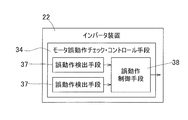
- the malfunction detection means 37 and the malfunction response control means 38 may be provided in the inverter device 22.
- the ECU 21 tends to be complicated as the functions of vehicle control become higher. Therefore, the malfunction detection means 37 and the malfunction response control means 38 are provided in the inverter device 22, thereby avoiding complication of the ECU 21.
- two malfunction detection means 37 are provided for one motor 6, and the malfunction response control means 38 applies to the motor 6 only when both malfunction detection means 37 detect malfunction.
- the malfunction detection control unit 37 detects a malfunction
- the malfunction countermeasure control is performed when the drive current is stopped, or the malfunction control corresponding to the braking control by the mechanical brakes 9 and 10 is performed. It can also be made to do.
- an abnormality has occurred in the malfunction detection means 37 itself, by providing two malfunction detection means 37, more reliable and accurate malfunction detection can be performed.
- three or more malfunction detection means 37 are provided for one motor 6, and the malfunction response control means 38, when a majority of the three or more malfunction detection means detect malfunctions, The drive current to the motor 6 may be stopped, or malfunction corresponding control that is braking control by the mechanical brakes 9 and 10 may be performed.
- the motor 6 may constitute an in-wheel motor drive device 8 having a wheel bearing 4 and a speed reducer 7 interposed between the wheel bearing 4 and the motor 6. Since the in-wheel motor drive device 8 drives the wheels 2 and 3 individually, the malfunction of the motor 6 has a large influence on stable running. For this reason, malfunction detection and malfunction countermeasure control according to the present invention become even more effective.
- the speed reducer 7 may be a cycloid speed reducer.
- the cycloid reducer can obtain a smooth high speed reduction ratio.
- torque is transmitted to the wheels 2 and 3 via the speed reducer 7 having a high reduction ratio, the torque caused by the destabilization of motor control is expanded and transmitted to the wheels 2 and 3. For this reason, malfunction detection and malfunction countermeasure control according to the present invention become even more effective.
- FIG. 1 is a block diagram of a conceptual configuration showing an electric vehicle according to an embodiment of the present invention in a plan view. It is a block diagram which shows the conceptual structure of the in-wheel motor unit of the same electric vehicle. It is a block diagram which shows the conceptual structure of the malfunction detection means in the same electric vehicle.
- FIG. 8 is a sectional view taken along line VIII-VIII in FIG. 7. It is a partial expanded sectional view of FIG. It is a longitudinal cross-sectional view of an example of the rotation sensor in the same electric vehicle.
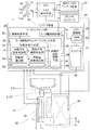
- This electric vehicle is a four-wheel drive vehicle in which both the left and right rear wheels 2 and the left and right front wheels 3 of the vehicle body 1 are drive wheels.
- the front wheel 3 is a steering wheel.
- Each of the wheels 2 and 3 has a tire and is supported by the vehicle body 1 via a wheel bearing 4.
- the wheel bearing 4 is abbreviated as “H / B” in FIG.
- the wheels 2 and 3 are driven by independent driving motors 6.
- the rotation of the motor 6 is transmitted to the drive wheel 2 via the speed reducer 7 and the wheel bearing 4.
- the motor 6, the speed reducer 7, and the wheel bearing 4 constitute an in-wheel motor drive device 8 that is one assembly part.
- the in-wheel motor drive device 8 is partially or entirely disposed in the wheel 2.
- Each in-wheel motor drive device 8 constitutes an in-wheel motor unit 30 together with an inverter device 22 described later.
- the wheels 2 and 3 are respectively provided with mechanical brakes 9 and 10 which are electric friction brakes.
- Wheels 3 and 3 which are steering wheels serving as left and right front wheels can be steered via a steering mechanism 11 and are steered by a steering mechanism 12.
- the steering mechanism 11 is a mechanism that changes the angles of the left and right knuckle arms 11b that hold the wheel bearings 4 by moving the tie rods 11a to the left and right.
- An EPS (electric power steering) motor 13 is driven by a command from the steering mechanism 12. It is driven and moved left and right via a rotation / linear motion conversion mechanism (not shown).
- the steering angle is detected by the steering angle sensor 15, and the sensor output is output to the ECU 21, and the information is used for acceleration / deceleration commands for the left and right wheels.
- a main ECU 21 that is an electric control unit that controls the entire vehicle, a plurality (four in the illustrated example) of inverter devices 22 that respectively control the respective driving motors 6 in accordance with commands from the ECU 21, and a brake controller 23 are mounted on the vehicle body 1.
- the ECU 21 includes a computer, a program executed by the computer, various electronic circuits, and the like. Note that the ECU 21 and other computers are, for example, microcomputers.
- the ECU 21 is roughly divided into a drive control unit 21a that performs control related to driving and a general control unit 21b that performs other controls, when roughly classified by function.
- the drive control unit 21a includes a torque distribution unit 48.
- the torque distribution unit 48 outputs an acceleration command output from the accelerator operation unit 16, a deceleration command output from the brake operation unit 17, and an output from the steering angle sensor 15. From the turning command to be generated, an acceleration / deceleration command to be given to the left and right wheel driving motors 6, 6 is generated as a torque command value and output to the inverter device 22.
- the torque distribution means 48 includes a braking torque command value for causing the motor 6 to function as a regenerative brake and a braking torque command value for operating the mechanical brakes 9 and 10 when a deceleration command output from the brake operation unit 17 is received. It has a function to allocate to.
- the braking torque command value that functions as a regenerative brake is reflected in the torque command value of the acceleration / deceleration command that is given to each traveling motor 6, 6.
- a braking torque command value for operating the mechanical brakes 9 and 10 is output to the brake controller 23.
- the torque distribution means 48 outputs the acceleration / deceleration commands to be output, the information on the tire rotation speed obtained from the rotation sensor 24 provided on the wheel bearings 4 of the wheels 2 and 3, and the on-vehicle sensors. It may have a function of correcting using the information.
- the accelerator operation unit 16 includes an accelerator pedal and a sensor 16a that detects the amount of depression and outputs the acceleration command.
- the brake operation unit 17 includes a brake pedal and a sensor 17a that detects the amount of depression and outputs the deceleration command.
- the general control unit 21b of the ECU 21 has a function of controlling various auxiliary machine systems 25, a function of processing input commands from the console operation panel 26, a function of displaying on the display means 27, and the like.
- the auxiliary machine system 25 is, for example, an air conditioner, a light, a wiper, a GPS, an air bag, and the like, and is shown here as a representative block.
- the brake controller 23 is a means for giving a braking command to the mechanical brakes 9 and 10 of the wheels 2 and 3 in accordance with a braking command output from the ECU 21, and is constituted by an electronic circuit, a microcomputer, or the like serving as an ECU dedicated to braking.
- the braking command output from the main ECU 21 includes a command generated by means for improving the safety of the ECU 21 in addition to a command generated by a deceleration command output from the brake operation unit 17.
- the brake controller 23 includes an antilock brake system.
- the inverter device 22 includes a power circuit unit 28 provided for each motor 6 and a motor control unit 29 that controls the power circuit unit 28.
- the motor control unit 29 has a function of outputting information (referred to as “IWM system information”) such as detection values and control values related to the in-wheel motor drive device 8 of the motor control unit 29 to the ECU 21.
- FIG. 2 is a block diagram showing a conceptual configuration of the in-wheel motor unit 30.
- the power circuit unit 28 of the inverter device 22 includes an inverter 31 that converts the DC power of the battery 19 (FIG. 1) into three-phase AC power used to drive the motor 6, and a PWM driver 32 that controls the inverter 31. Is done.
- the motor 6 is a three-phase synchronous motor, for example, an IPM type (embedded magnet type) synchronous motor or the like.
- the inverter 31 is composed of a plurality of semiconductor switching elements (not shown), and the PWM driver 32 performs pulse width modulation on the input current command and gives an on / off command to each of the semiconductor switching elements.
- the motor control unit 29 includes a computer, a program executed on the computer, and an electronic circuit.
- the motor control unit 29 converts it into a current command in accordance with an acceleration / deceleration command by a torque command or the like given from the ECU 21 that is the host control means, and gives a current command to the PWM driver 32 of the power circuit unit 28. Further, the motor control unit 29 obtains a motor current value flowing from the inverter 31 to the motor 6 from the current sensor 35 and performs current feedback control. In this current control, the rotation angle of the rotor of the motor 6 is obtained from the angle sensor 36, and control according to the rotation angle such as vector control is performed.
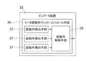
- the motor control unit 29 is provided with a motor malfunction check / control unit 34 and an abnormality report unit 47 including the following malfunction detection means 37 and malfunction response control means 38.
- the abnormality reporting means 47 causes the ECU 21 to detect malfunctions or deal with malfunctions when the malfunction detection means 37 detects malfunctions, when the malfunction handling control means 38 performs processing corresponding to malfunctions, or both. It is a means for transmitting a signal to be a processing report.
- the ECU 21 is provided with means for performing a corresponding control upon receiving the report from the abnormality report means 47 and a means for displaying on the console display means 27 for notifying the driver (none of which is shown).
- the malfunction detection means 37 constantly monitors any one of the torque command output from the ECU 21 and the rotation signal, rotation direction signal, and motor current of the motor 6 or wheels 2 and 3 driven by the motor 6. This is means for detecting a malfunction of the motor 6 in accordance with a predetermined rule based on the information obtained.
- the rotation signals and rotation direction signals of the wheels 2 and 3 are obtained from the output of the angle sensor 36 of the motor rotor provided in the motor 6 or the rotation sensor 24 provided in the wheel bearing 4. When the rotation direction signal is obtained from the rotation sensor 24, the rotation sensor 24 uses an output that can determine the rotation direction.
- Malfunction handling control means 38 is a means that, when a malfunction detection is detected by the malfunction detection means 37, stops driving current to the motor 6 and brakes by the mechanical brakes 9 and 10 or both. The drive current is stopped by the malfunction handling control means 38 via the motor drive control unit 33. When the mechanical brakes 9 and 10 are braked, a braking command is given to the brake controller 23. The brake controller 23 causes all the mechanical brakes 9 and 10 of the vehicle to perform a braking operation when, for example, there is a braking command from the malfunction corresponding control means 38 in any of the inverter devices 22.
- the malfunction handling control means 38 When detecting a malfunction of one motor 6, the malfunction handling control means 38 not only stops the drive current to the motor 6 in which the malfunction has been detected, but also stops the drive current to the other motor 6. It is good to do so. In this case, the drive current to all the motors 6 of the vehicle may be stopped, and the drive current to the motors 6 of the other wheels 2 and 3 at the same position in the front-rear direction of the vehicle is stopped. You may do it. For example, when a malfunction of the motor 6 of the left wheel 2 that is the rear wheel is detected, the motor 6 of the right wheel 2 that is also the rear wheel is stopped in addition to the wheel 2.
- signal transmission is performed via the ECU 21.
- signal transmission may be performed directly between the inverter devices 22.
- the malfunction corresponding control means 38 In the case of passing through the ECU 21, the malfunction corresponding control means 38 outputs a signal that causes the ECU 21 to detect malfunction or a signal that causes the drive current of another motor 6 to stop. In response to the malfunction detection signal or the signal for stopping the separate motor driving current, the ECU 21 instructs the inverter device 22 of the separate motor 6 to stop the driving current. 4) may be provided.
- each inverter device 22 When signal transmission is directly performed between the inverter devices 22, each inverter device 22 receives a drive current stop signal sent from another inverter device 22 and stops the drive current of the motor 6 controlled by itself. Means (not shown) are provided in the motor control unit 29.
- FIG. 3 is a conceptual diagram of a specific example of the malfunction detection means 37.
- the malfunction detection means 37 is provided with a rotation direction instruction determination unit 41 and a rotation direction abnormality determination unit 42 as a malfunction detection unit for the rotation direction abnormality of the motor 6.
- a rotation speed estimation unit 43 and a rotation speed abnormality determination unit 44 are provided as malfunction detection units for rotation speed abnormality
- a motor current estimation unit 45 and a current abnormality determination unit 46 serve as malfunction detection units for motor current abnormality. Is provided.
- the rotation direction instruction determination unit 41 is either forward or reverse (forward or backward of the vehicle) in the rotational direction in the drive command of the ECU 21. Determine if the direction.
- the rotation direction abnormality determination unit 42 detects the rotation direction A of the drive command from the ECU 21 determined by the rotation direction instruction determination unit 41 and the actual motor rotation direction B, that is, the rotation sensor 24 or the angle sensor 36 (FIG. 2). The rotation direction B is compared, and if it is different, the motor abnormality determination result is output.
- the rotation speed estimation unit 43 is based on this torque command, and the rotation number of the motor 6 when driven by the drive command of the ECU 21 (in other words, the rotation speed). Is estimated.
- the rotation speed abnormality determination unit 44 compares the rotation number C estimated by the rotation number estimation unit 43 with the actual motor rotation number D, that is, the rotation number D detected by the rotation sensor 24 or the angle sensor 36, and sufficiently If there is a large difference, the motor abnormality determination result is output. Whether the estimated rotational speed C and the actual motor rotational speed D are D >> C or D ⁇ C, the motor is abnormal. It is set as appropriate to determine how much difference the motor is determined to be abnormal.
- the motor current estimation unit 45 estimates the current of the motor 6 when driven by this torque command.
- the current abnormality determination unit 46 compares the motor current E estimated by the motor current estimation unit 45 with the actual motor current F, that is, the motor current F detected by the current sensor 35. Outputs the abnormality judgment result. Whether the estimated motor current E and the actual motor current F are F >> E or F ⁇ E, the motor is abnormal. It is set as appropriate to determine how much difference the motor is determined to be abnormal.
- the malfunction detection means 37 constantly monitors any one of the torque command output from the ECU 21, the rotation signal of the motor 6 or the wheels 2 and 3 driven by the motor 6, the rotation direction signal, and the motor current. Based on the obtained information, a malfunction of the motor is detected according to a predetermined rule.
- the rotation direction instruction determination unit 41 determines the rotation direction A indicated by the torque command from the torque command that is a drive command given from the ECU 21 to the inverter device 22.
- the rotation direction A thus determined and the actual motor rotation direction B are compared by the rotation direction abnormality determination unit 42, and if they are different, a determination result of motor abnormality is output.
- the rotation speed estimation unit 43 estimates the rotation speed of the motor 6 when driven by this torque command from the torque command given from the ECU 21 to the inverter device 22, and the estimated rotation speed C and the actual detection are detected.
- the motor rotation speed D is compared with the rotation speed abnormality determination unit 44, and if both the rotation speeds C and D are sufficiently different, a motor abnormality determination result is output.
- the motor current estimating unit 45 estimates the current of the motor 6 when driven by this torque command from the torque command given from the ECU 21 to the inverter device 22, and the estimated driving current and the actually detected motor current are estimated. F is compared with the current abnormality determination unit 46, and if both current values are sufficiently different, a determination result of motor abnormality is output.
- the malfunction handling control unit 38 in FIG. 2 stops driving current to the motor 6 or brakes as control corresponding to the malfunction. Braking by 9, 10 or both are performed. When braking is performed by the brakes 9 and 10, the brakes 9 and 10 of all the wheels 2 and 3 are braked, or both the left and right brakes 9 and 10 are arranged between the rear wheels or between the front wheels. To brake. Also, when stopping the drive current to the motor 6, it is preferable to stop the current simultaneously for the motors 6 other than the motor 6 in which the malfunction is detected as described above.
- the abnormality report means 47 reports the content of the malfunction countermeasure control to the ECU 21.
- the ECU 21 performs appropriately determined control so that cooperative control of the entire vehicle can be performed, and the driver displays abnormalities of the motor 6 and controls corresponding thereto on the display means 27 of the console. Display to indicate that it has been done.
- the display of the occurrence of an abnormality may be performed in response to a signal in which an abnormality is detected by the malfunction detection means 37.
- the combination of the rotation direction instruction determination unit 41 and the rotation direction abnormality determination unit 42, the combination of the rotation number estimation unit 43 and the rotation number abnormality determination unit 44, the motor current estimation unit 45 and the current abnormality determination unit 46 is not limited.
- the malfunction countermeasure control means 38 controls the braking of the driving force to the motor 6 or the braking by the mechanical brakes 9 and 10 only when both of the two malfunction detection means 37 detect malfunction. Some malfunction countermeasure control may be performed, and when any malfunction detection means 37 detects a malfunction, the malfunction countermeasure control may be performed. Although there is a possibility that an abnormality has occurred in the malfunction detection means 37 itself, by providing two malfunction detection means 37, more reliable and accurate malfunction detection can be performed.
- three malfunction detection means 37 are provided for one motor 6, and the malfunction response control means 38 is used when a majority of the three or more malfunction detection means 37 detects malfunction.
- the malfunction control may be performed.
- the specific configuration of the malfunction detection means 37 is the configuration described above with reference to FIG. 5 and 6, a malfunction is detected by one of the malfunction detection means 37, but no malfunction is detected by the other malfunction detection means 37, and malfunction handling control is performed by the malfunction handling control means 38. If not, the fact may be reported to the ECU 21 by the abnormality reporting means 47 in FIG. 2, and the display means 27 in FIG. 5 and 6, the plurality of malfunction detection means 37 provided may have the same configuration or different configurations.
- the in-wheel motor drive device 8 includes a reduction gear 7 interposed between a wheel bearing 4 and a motor 6, and a hub of the drive wheel 2 supported by the wheel bearing 4 and a rotation output shaft 74 of the motor 6. They are connected on the same axis.
- the speed reducer 7 is a cycloid speed reducer, in which eccentric portions 82a and 82b are formed on a rotational input shaft 82 that is coaxially connected to a rotational output shaft 74 of the motor 6, and bearings 85 are respectively provided on the eccentric portions 82a and 82b.
- the curved plates 84a and 84b are mounted, and the eccentric motion of the curved plates 84a and 84b is transmitted to the wheel bearing 4 as rotational motion.
- the side closer to the outer side in the vehicle width direction of the vehicle when attached to the vehicle is referred to as the outboard side, and the side closer to the center of the vehicle is referred to as the inboard side.
- the wheel bearing 4 includes an outer member 51 in which a double row rolling surface 53 is formed on the inner periphery, an inner member 52 in which a rolling surface 54 facing each of the rolling surfaces 53 is formed on the outer periphery, and these
- the outer member 51 and the inner member 52 are composed of double-row rolling elements 55 interposed between the rolling surfaces 53 and 54 of the inner member 52.
- the inner member 52 also serves as a hub for attaching the drive wheels.
- the wheel bearing 4 is a double-row angular ball bearing, and the rolling elements 55 are made of balls and are held by a cage 56 for each row.
- the rolling surfaces 53 and 54 have a circular arc cross section, and the rolling surfaces 53 and 54 are formed so that the contact angles are aligned with the back surface.
- An end on the outboard side of the bearing space between the outer member 51 and the inner member 52 is sealed with a seal member 57.
- the outer member 51 is a stationary raceway, has a flange 51a attached to the housing 83b on the outboard side of the speed reducer 7, and is formed as an integral part as a whole.
- the flange 51a is provided with bolt insertion holes 64 at a plurality of locations in the circumferential direction.
- the housing 83b is provided with a bolt screw hole 94 whose inner periphery is threaded at a position corresponding to the bolt insertion hole 64.
- the outer member 51 is attached to the housing 83b by screwing the mounting bolt 65 inserted into the bolt insertion hole 94 into the bolt screwing hole 94.
- the inner member 52 is a rotating raceway, and the outboard side member 59 having a hub flange 59a for wheel mounting and the outboard side member 59 are fitted to the inner periphery of the outboard side member 59.
- the inboard side material 60 is integrated with the outboard side material 59 by fastening.
- the rolling surface 54 of each row is formed in each of the outboard side material 59 and the inboard side material 60.
- a through hole 61 is provided in the center of the inboard side member 60.
- the hub flange 59a is provided with press-fit holes 67 for hub bolts 66 at a plurality of locations in the circumferential direction.
- a cylindrical pilot portion 63 that guides driving wheels and braking components (not shown) protrudes toward the outboard side.
- a cap 68 that closes the outboard side end of the through hole 61 is attached to the inner periphery of the pilot portion 63.
- the speed reducer 7 is a cycloid speed reducer, and two curved plates 84a and 84b formed with wavy trochoid curves having a gentle outer shape as shown in FIG.
- the shaft 82 is attached to each eccentric part 82a, 82b.
- a plurality of outer pins 86 for guiding the eccentric movements of the curved plates 84a and 84b on the outer peripheral side are provided across the housing 83b, and a plurality of inner pins 88 attached to the inboard side member 60 of the inner member 2 are provided.
- the curved plates 84a and 84b are engaged with a plurality of circular through holes 89 provided in the inserted state.
- the rotation input shaft 82 is spline-coupled with the rotation output shaft 74 of the motor 6 and rotates integrally.
- the rotary input shaft 82 is supported at both ends by two bearings 90 on the inboard side housing 83a and the inner diameter surface of the inboard side member 60 of the inner member 52.
- the curved plates 84a and 84b attached to the rotation input shaft 82 that rotates together with the motor 6 perform an eccentric motion.
- the eccentric motions of the curved plates 84 a and 84 b are transmitted to the inner member 52 as rotational motion by the engagement of the inner pins 88 and the through holes 89.
- the rotation of the inner member 52 is decelerated with respect to the rotation of the rotation output shaft 74. For example, a reduction ratio of 1/10 or more can be obtained with a single-stage cycloid reducer.
- the two curved plates 84a and 84b are attached to the eccentric portions 82a and 82b of the rotary input shaft 82 so as to cancel out the eccentric motion with each other, and are mounted on both sides of the eccentric portions 82a and 82b.
- a counterweight 91 that is eccentric in the direction opposite to the eccentric direction of the eccentric portions 82a and 82b is mounted so as to cancel the vibration caused by the eccentric movement of the curved plates 84a and 84b.
- bearings 92 and 93 are attached to the outer pins 86 and the inner pins 88, and outer rings 92a and 93a of the bearings 92 and 93 are respectively connected to the curved plates 84a and 84b. It comes into rolling contact with the outer periphery and the inner periphery of each through-hole 89. Therefore, the contact resistance between the outer pin 86 and the outer periphery of each curved plate 84a, 84b and the contact resistance between the inner pin 88 and the inner periphery of each through hole 89 are reduced, and the eccentric motion of each curved plate 84a, 84b is smooth. Can be transmitted to the inner member 52 as a rotational motion.
- the motor 6 is a radial gap type IPM motor in which a radial gap is provided between a motor stator 73 fixed to a cylindrical motor housing 72 and a motor rotor 75 attached to the rotation output shaft 74.
- the rotation output shaft 74 is cantilevered by two bearings 76 on the cylindrical portion of the housing 83 a on the inboard side of the speed reducer 7.
- the motor stator 73 includes a stator core portion 77 and a coil 78 made of a soft magnetic material.
- the stator core portion 77 is held by the motor housing 72 with its outer peripheral surface fitted into the inner peripheral surface of the motor housing 72.
- the motor rotor 75 includes a rotor core portion 79 that is fitted on the rotation output shaft 74 concentrically with the motor stator 73, and a plurality of permanent magnets 80 that are built in the rotor core portion 79.
- the motor 6 is provided with an angle sensor 36 that detects a relative rotation angle between the motor stator 73 and the motor rotor 75.
- the angle sensor 36 detects and outputs a signal representing a relative rotation angle between the motor stator 73 and the motor rotor 75, and an angle calculation circuit 71 that calculates an angle from the signal output from the angle sensor body 70. And have.
- the angle sensor main body 70 includes a detected portion 70a provided on the outer peripheral surface of the rotation output shaft 74, and a detecting portion 70b provided in the motor housing 72 and disposed in close proximity to the detected portion 70a, for example, in the radial direction. Become.
- the detected portion 70a and the detecting portion 70b may be arranged close to each other in the axial direction.
- a magnetic encoder or a resolver is used as each angle sensor 36.
- the rotation control of the motor 6 is performed by the motor control unit 29 (FIGS. 1 and 2).
- each phase of each wave of alternating current flowing through the coil 78 of the motor stator 73 based on the relative rotation angle between the motor stator 73 and the motor rotor 75 detected by the angle sensor 36. Is controlled by the motor drive control unit 33 of the motor control unit 29.
- the wiring of the motor current of the in-wheel motor drive device 8 and the wiring of various sensor systems and command systems are collectively performed by a connector 99 provided in the motor housing 72 and the like.
- FIG. 10 shows an example of the rotation sensor 24 shown in FIGS.
- the rotation sensor 24 includes a magnetic encoder 24a provided on the outer periphery of the inner member 52 in the wheel bearing 4, and a magnetic sensor 24b provided on the outer member 51 so as to face the magnetic encoder 24a.
- the magnetic ender 24a is a ring-shaped member in which magnetic poles N and S are alternately magnetized in the circumferential direction.
- the rotation sensor 24 is disposed between both rows of rolling elements 55, 55, but may be installed at the end of the wheel bearing 4.
- the ECU 21 and the inverter device 22 are provided apart from each other, but the ECU 21 and the inverter device 22 may be configured by the same computer.
Landscapes
- Engineering & Computer Science (AREA)
- Transportation (AREA)
- Mechanical Engineering (AREA)
- Life Sciences & Earth Sciences (AREA)
- Sustainable Development (AREA)
- Sustainable Energy (AREA)
- Power Engineering (AREA)
- Chemical & Material Sciences (AREA)
- Combustion & Propulsion (AREA)
- Electric Propulsion And Braking For Vehicles (AREA)
- Arrangement Or Mounting Of Propulsion Units For Vehicles (AREA)
- Regulating Braking Force (AREA)
Abstract
モータが制御系のノイズ等で誤動作した場合に、瞬時にこれを判断して安全処置を採ることができる電気自動車を提供する。ECU(21)の出力するトルク指令と、モータ(6)またはこのモータ(6)で駆動される車輪(2,3)の回転信号、回転方向信号、およびモータ電流のいずれかとを常時監視し、この監視した情報を基に、定められた規則に従ってモータ(6)の誤動作を検出する誤動作検出手段(37)を設ける。この誤動作検出手段(37)で誤動作が検出されるとモータ(6)への駆動電流の停止、および機械式ブレーキ(9,10)による制動のいずれかまたは両方を行わせる誤動作対応制御手段(38)を設ける。
Description
本出願は、2011年2月25日出願の特願2011-039412の優先権を主張するものであり、その全体を参照により本願の一部をなすものとして引用する。
この発明は、インホイールモータ駆動装置を備えたバッテリ駆動、燃料電池駆動等の電気自動車に関し、特に、モータ異常時のフェールセーフの制御に関する。
電気自動車のモータ制御は、通常、マイコン(マイクロコンピュータ)を使って行う方式が採られる。また、その制御系として、車両全般を制御するメインの電気制御ユニットであるECUと、インバータ装置とが設けられる。インバータ装置は、バッテリの直流電力を前記モータの駆動に用いる交流電力に変換するインバータを含むパワー回路部と、ECUから与えられるトルク指令に従って前記パワー回路部を制御するモータコントロール部とを有する。また、電気自動車として、車輪用軸受、モータ、および減速機からなるインホイールモータ駆動装置が用いられる場合がある。
上記のように、電気自動車のモータ制御は、通常、マイコンを使って行う方式が採られるが、万が一、このマイコンに電磁ノイズまたは静電ノイズが影響を及ぼした場合には、モータコントローラ自体が正常に動作できなくなる可能性がある。特に、電気自動車の駆動源であるモータを、高い減速比を有する減速機を介して車輪にトルク伝達する場合、モータ制御の不安定化を原因としたトルクは拡大されて車輪に伝達されるため、このモータのコントーラの信頼性は重要となる。
この発明の目的は、モータが制御系のノイズ等で誤動作した場合に、瞬時にこれを判断して安全処置を採ることができる電気自動車を提供することである。以下、この発明の概要について、実施形態を示す図面中の符号を用いて説明する。
この発明の電気自動車は、車輪2,3を駆動するモータ6と、車両全般を制御する電気制御ユニットであるECU21と、バッテリの直流電力を前記モータ6の駆動に用いる交流電力に変換するインバータ31を含むパワー回路部28および前記ECU21から与えられるトルク指令に従って前記パワー回路部28を制御するモータコントロール部29を有するインバータ装置22と、車輪2,3を制動する機械式ブレーキ9,10とを備えた電気自動車であって、前記ECU21の出力する前記トルク指令と、前記モータ6またはこのモータ6で駆動される車輪2,3の回転信号、回転方向信号、およびモータ電流のいずれかを常時監視し、この監視した情報を基に、定められた規則に従ってモータ6の誤動作を検出する誤動作検出手段37と、この誤動作検出手段37で誤動作が検出されると前記モータ6への駆動電流の停止もしくは低減、および前記機械式ブレーキ9,10による制動のいずれかまたは両方を行わせる誤動作対応制御手段38とを設けたものである。
なお、機械式ブレーキ9,10による制動は、異常を発したモータ6で駆動される車輪2,3だけでなく、車両に備えられた他の車輪2,3の制動も行うようにするのが良い。例えば、左右方向の一方の車輪2,3のモータ6に異常が発生した場合、左右両輪の機械式ブレーキ9,10による制動を行わせるのが良い。前記誤動作検出手段37および誤動作対応制御手段38、ECU21およびインバータ装置22のいずれに設けても良く、またこれらECU21およびインバータ装置22とは別に設けても良い。
前記モータコントロール部29等に電磁ノイズまたは静電ノイズが影響を及ぼした場合、ECU21からのトルク指令に対して、モータ6は回転方向や回転速度の誤動作を生じることがある。前記誤動作検出手段37は、ECU21の出力するトルク指令と、モータ6、またはこのモータ6で駆動される車輪2,3の回転信号、回転方向信号、およびモータ電流のいずれかを常時監視し、この監視した情報を基に、定められた規則に従ってモータの誤動作を検出する。検出されるモータ6の誤動作は、例えば、ECU21からのトルク指令に対する回転方向や回転速度の誤動作である。誤動作対応制御手段38は、前記誤動作検出手段37で誤動作が検出されると前記モータ6への駆動電流の停止、および前記機械式ブレーキ9,10による制動のいずれか、または両方を行わせる。
このように、モータ異常を常に監視し、モータ6への駆動電流の停止、または機械式ブレーキ9,10による制動を行わせるため、運転者の意思に反する車両の逆方向への走行や、加速等が回避され、即座に安全性が得られる。
この発明において、前記誤動作検出手段37は、前記ECU21から与えられるトルク指令よりモータ6の回転すべき回転方向を判定する回転方向指示判別部41と、前記モータ6またはこのモータ6で駆動される車輪2,3の回転信号、回転方向信号、およびモータ電流のいずれかから得られる回転方向とを比較してモータ6の回転方向異常を判定する回転方向異常判定部42とを有するものとしても良い。モータ6の回転方向異常は、運転者の操作に反した車両走行の逆方向走行により、安全性に大きな影響が生じるが、このような回転方向異常時にモータ電流の停止や機械式ブレーキ9,10による制動を行わせることで、安全性が確保される。
この発明において、前記誤動作検出手段37は、前記ECU21から与えられるトルク指令よりモータ6の回転すべき回転数を判定する回転数推定部43と、前記モータ6またはこのモータ6で駆動される車輪2,3の回転信号とを比較してモータ6の回転数異常を判定する回転数異常判定部44とを有するものとしても良い。ノイズにより、運転者の操作に反した急激な加速が生じる恐れがあるが、回転数の異常を判定することで、上記のような操作に反した急激な加速等が回避され、安全性が確保される。
この発明において、それぞれ別の車輪2,3を駆動する複数のモータ6を備えた電気自動車の場合に、前記誤動作対応制御手段38は、一つのモータ6の誤動作の検出を検出したときに、その誤動作が検出されたモータ6への駆動電流の停止もしくは低減と、他のモータ6への駆動電流の停止もしくは低減とを行わせるようにするのが良い。各車輪2,3が別個のモータ6で駆動される車両では、一つのモータ6だけの駆動電流を停止した場合、その駆動電流を停止したモータ6の車輪は回転自在となるが、車両の左右または前後で駆動がアンバランスとなり、直進性に影響することがある。このため、一つのモータ6の駆動電流を停止する場合は、他のモータ6への駆動電流も停止することが、直進性に影響を与えない安定した走行の上で好ましい。
この発明において、前記誤動作検出手段37および前記誤動作対応制御手段38を前記インバータ装置22に設けても良い。ECU21は、車両制御の高機能化に伴って複雑化の傾向にある。そのため、誤動作検出手段37および前記誤動作対応制御手段38をインバータ装置22に設けることで、ECU21の複雑化が回避される。また、配線上からも、モータ6に対してECU21よりも近い位置になるインバータ装置22に誤動作検出手段37および誤動作対応制御手段38を設けることが有利である。
この発明において、一つのモータ6に対して前記誤動作検出手段37を2つ設け、前記誤動作対応制御手段38は、2つの誤動作検出手段37の両方が誤動作を検出した場合にのみ、前記モータ6への駆動電流の停止、または前記機械式ブレーキ9,10による制動の制御である誤動作対応制御を行わせるか、またはいずれか一方の誤動作検出手段37が誤動作を検出した場合に、前記誤動作対応制御を行わせるものとしても良い。誤動作検出手段37自体に異常が発生している恐れがあるが、誤動作検出手段37を2つ設けることで、より確実で正確な誤動作検知が行える。
この発明において、一つのモータ6に対して前記誤動作検出手段37を3つ以上設け、前記誤動作対応制御手段38は、前記3つ以上の誤動作検出手段のうちの過半数が誤動作を検出した場合に、前記モータ6への駆動電流の停止、または前記機械式ブレーキ9,10による制動の制御である誤動作対応制御を行わせるものとしても良い。3つ以上の誤動作検出手段37を設けてそれらの出力の多数決で誤動作と判定することで、より正確な誤動作検知が行える。
この発明において、前記モータ6は、車輪用軸受4と、この車輪用軸受4とモータ6の間に介在した減速機7とを有するインホイールモータ駆動装置8を構成するものであっても良い。インホイールモータ駆動装置8では、個別に車輪2,3を駆動するため、そのモータ6の誤動作は、安定した走行への影響が大きい。そのため、この発明による誤動作検出と誤動作対応制御が、より一層効果的となる。
この発明において、前記減速機7がサイクロイド減速機であっても良い。サイクロイド減速機は円滑な動作高減速比が得られる。高減速比を有する減速機7を介して車輪2,3にトルク伝達する場合、モータ制御の不安定化を原因としたトルクは拡大されて車輪2,3に伝達される。そのため、この発明による誤動作検出と誤動作対応制御が、より一層効果的となる。
請求の範囲および/または明細書および/または図面に開示された少なくとも2つの構成のどのような組合せも、本発明に含まれる。特に、請求の範囲の各請求項の2つ以上のどのような組合せも、本発明に含まれる。
この発明は、添付の図面を参考にした以下の好適な実施形態の説明から、より明瞭に理解されるであろう。しかしながら、実施形態および図面は単なる図示および説明のためのものであり、この発明の範囲を定めるために利用されるべきものではない。この発明の範囲は添付の請求の範囲によって定まる。添付図面において、複数の図面における同一の符号は、同一または相当する部分を示す。
この発明の一実施形態に係る電気自動車を平面図で示す概念構成のブロック図である。
同電気自動車のインホイールモータユニットの概念構成を示すブロック図である。
同電気自動車における誤動作検出手段の概念構成を示すブロック図である。
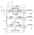
同電気自動車におけるECU、各インバータ装置、およびそのモータ誤動作チェック・コントロール手段の概念構成を示すブロック図である。
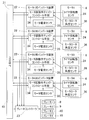
同電気自動車におけるモータ誤動作チェック・コントロール手段の変形例の概念構成を示すブロック図である。
同電気自動車におけるモータ誤動作チェック・コントロール手段の他の変形例の概念構成を示すブロック図である。
同電気自動車におけるインホイールモータ駆動装置の破断正面図である。
図7のVIII-VIII線断面図である。
図8の部分拡大断面図である。
同電気自動車における回転センサの一例の縦断面図である。
この発明の一実施形態を図1ないし図10と共に説明する。この電気自動車は、車体1の左右の後輪となる車輪2および左右の前輪となる車輪3が共に駆動輪とされた4輪駆動の自動車である。前輪となる車輪3は操舵輪とされている。各車輪2,3は、いずれもタイヤを有し、それぞれ車輪用軸受4を介して車体1に支持されている。車輪用軸受4は、図1ではハブベアリングの略称「H/B」を付してある。各車輪2,3は、それぞれ独立の走行用のモータ6により駆動される。モータ6の回転は、減速機7および車輪用軸受4を介して駆動輪2に伝達される。これらモータ6、減速機7、および車輪用軸受4は、互いに一つの組立部品であるインホイールモータ駆動装置8を構成している。インホイールモータ駆動装置8は、一部または全体が車輪2内に配置される。各インホイールモータ駆動装置8は、後述のインバータ装置22と共に、インホイールモータユニット30を構成する。各車輪2,3には、電動式等の摩擦ブレーキである機械式のブレーキ9,10がそれぞれ設けられている。
左右の前輪となる操舵輪である車輪3,3は、転舵機構11を介して転舵可能であり、操舵機構12により操舵される。転舵機構11は、タイロッド11aを左右移動させることで、車輪用軸受4を保持した左右のナックルアーム11bの角度を変える機構であり、操舵機構12の指令によりEPS(電動パワーステアリング)モータ13を駆動させ、回転・直線運動変換機構(図示せず)を介して左右移動させられる。操舵角は操舵角センサ15で検出し、このセンサ出力はECU21に出力され、その情報は左右輪の加速・減速指令等に使用される。
制御系を説明する。自動車全般の制御を行う電気制御ユニットであるメインのECU21と、このECU21の指令に従って各走行用のモータ6の制御をそれぞれ行う複数(図示の例では4つ)のインバータ装置22と、ブレーキコントローラ23とが、車体1に搭載されている。ECU21は、コンピュータとこれに実行されるプログラム、並びに各種の電子回路等で構成される。なお、ECU21や他の各コンピュータは、例えばマイクロコンピュータである。
ECU21は、機能別に大別すると駆動に関する制御を行う駆動制御部21aと、その他の制御を行う一般制御部21bとに分けられる。駆動制御部21aは、トルク配分手段48を有していて、トルク配分手段48は、アクセル操作部16の出力する加速指令と、ブレーキ操作部17の出力する減速指令と、操舵角センサ15の出力する旋回指令とから、左右輪の走行用モータ6,6に与える加速・減速指令をトルク指令値として生成し、インバータ装置22へ出力する。トルク配分手段48は、ブレーキ操作部17の出力する減速指令があったときに、モータ6を回生ブレーキとして機能させる制動トルク指令値と、機械式のブレーキ9,10を動作させる制動トルク指令値とに配分する機能を持つ。回生ブレーキとして機能させる制動トルク指令値は、各走行用のモータ6,6に与える加速・減速指令のトルク指令値に反映させる。機械式のブレーキ9,10を動作させる制動トルク指令値は、ブレーキコントローラ23へ出力する。
トルク配分手段48は、上記の他に、出力する加速・減速指令を、各車輪2,3の車輪用軸受4に設けられた回転センサ24から得られるタイヤ回転数の情報や、車載の各センサの情報を用いて補正する機能を有していても良い。アクセル操作部16は、アクセルペダルとその踏み込み量を検出して前記加速指令を出力するセンサ16aとでなる。ブレーキ操作部17は、ブレーキペダルとその踏み込み量を検出して前記減速指令を出力するセンサ17aとでなる。
ECU21の一般制御部21bは、各種の補機システム25を制御する機能、コンソールの操作パネル26からの入力指令を処理する機能、表示手段27に表示を行う機能などを有する。前記補機システム25は、例えば、エアコン、ライト、ワイパー、GPS、アエバッグ等であり、ここでは代表して一つのブロックとして示す。
ブレーキコントローラ23は、ECU21から出力される制動指令に従って、各車輪2,3の機械式のブレーキ9,10に制動指令を与える手段であり、制動専用のECUとなる電子回路やマイコン等により構成される。メインのECU21から出力される制動指令には、ブレーキ操作部17の出力する減速指令によって生成される指令の他に、ECU21の持つ安全性向上のための手段によって生成される指令がある。ブレーキコントローラ23は、この他にアンチロックブレーキシステムを備える。
インバータ装置22は、各モータ6に対して設けられたパワー回路部28と、このパワー回路部28を制御するモータコントロール部29とで構成される。モータコントロール部29は、このモータコントロール部29が持つインホイールモータ駆動装置8に関する各検出値や制御値等の各情報(「IWMシステム情報」と称す)をECU21に出力する機能を有する。
図2は、インホイールモータユニット30の概念構成を示すブロック図である。インバータ装置22のパワー回路部28は、バッテリ19(図1)の直流電力をモータ6の駆動に用いる3相の交流電力に変換するインバータ31と、このインバータ31を制御するPWMドライバ32とで構成される。モータ6は3相の同期モータ、例えばIPM型(埋込磁石型)同期モータ等からなる。インバータ31は、複数の半導体スイッチング素子(図示せず)で構成され、PWMドライバ32は、入力された電流指令をパルス幅変調し、前記各半導体スイッチング素子にオンオフ指令を与える。
モータコントロール部29は、コンピュータとこれに実行されるプログラム、および電子回路により構成される。モータコントロール部29は、上位制御手段であるECU21から与えられるトルク指令等による加速・減速指令に従い、電流指令に変換して、パワー回路部28のPWMドライバ32に電流指令を与える。また、モータコントロール部29は、インバータ31からモータ6に流すモータ電流値を電流センサ35から得て、電流フィードバック制御を行う。この電流制御では、モータ6のロータの回転角を角度センサ36から得て、ベクトル制御等の回転角に応じた制御を行う。
この実施形態は、モータコントロール部29に、次の誤動作検出手段37および誤動作対応制御手段38からなるモータ誤動作チェック・コントロール手段34および異常報告手段47を設けたものである。
異常報告手段47は、誤動作検出手段37で誤動作を検出した場合、または誤動作対応制御手段38で誤動作に対応する処理を行った場合、またはその両方の場合に、ECU21に、その誤動作検出や誤動作対応処理の報告となる信号を送信する手段である。ECU21は、この異常報告手段47の報告を受けて、対応する制御を行う手段や、コンソールの表示手段27に、運転者に知らせるための表示を行う手段(いずれも図示せず)が設けられる。
誤動作検出手段37は、ECU21の出力する前記トルク指令と、モータ6またはこのモータ6で駆動される車輪2,3の回転信号、回転方向信号、およびモータ電流のいずれかを常時監視し、この監視した情報を基に、定められた規則に従ってモータ6の誤動作を検出する手段である。車輪2,3の回転信号および回転方向信号は、モータ6に設けられたモータロータの角度センサ36、または車輪用軸受4に設けられた回転センサ24の出力から得る。回転方向信号を回転センサ24から得る場合、回転センサ24には回転方向の判別が可能な出力を行うものを用いる。
誤動作対応制御手段38は、誤動作検出手段37で誤動作が検出されると、モータ6への駆動電流の停止、および前記機械式ブレーキ9,10による制動のいずれかまたは両方を行わせる手段である。誤動作対応制御手段38による駆動電流の停止は、モータ駆動制御部33を介して行わせる。機械式ブレーキ9,10に制動させる場合は、ブレーキコントーラ23に制動の指令を与える。ブレーキコントーラ23は、例えば、いずれかのインバータ装置22における誤動作対応制御手段38から制動指令があった場合は、車両の全ての機械式ブレーキ9,10に制動動作を行わせる。
誤動作対応制御手段38は、一つのモータ6の誤動作を検出したときに、その誤動作が検出されたモータ6への駆動電流の停止だけでなく、他のモータ6への駆動電流の停止も行わせるようにするのが良い。この場合に、車両の全てのモータ6への駆動電流の停止を行わせるようにしても良く、車両の前後方向の同じ位置にある他の車輪2,3のモータ6への駆動電流の停止するようにしても良い。例えば、後輪となる左の車輪2のモータ6の誤動作を検出したときに、この車輪2の他に、同じく後輪となる右の車輪2のモータ6を停止させるようにする。
誤動作対応制御手段38により、その誤動作対応制御手段38が設けられたインバータ装置22で駆動されるモータ6とは別のモータ6の駆動電流の停止を行わせる場合、ECU21を介して信号伝達を行うようにしても良く、インバータ装置22間で直接に信号伝達を行うようにしても良い。
ECU21を介する場合、誤動作対応制御手段38からECU21に誤動作を検出した信号、または別のモータ6の駆動電流の停止を行わせる信号を出力する。ECU21には前記誤動作検出の信号、または別モータ駆動電流の停止を行わせる信号を受けて、前記別のモータ6のインバータ装置22へ駆動電流の停止の命令を行わせる別モータ対応制御手段49(図4)を設けても良い。
インバータ装置22間で直接に信号伝達を行う場合は、各インバータ装置22に、他のインバータ装置22から送られる駆動電流の停止の信号を受信して自己の制御するモータ6の駆動電流を停止させる手段(図示せず)を、モータコントロール部29に設ける。
図3は誤動作検出手段37の具体例の概念図である。この例では、誤動作検出手段37は、モータ6の回転方向異常に対する誤動作検出部として、回転方向指示判別部41および回転方向異常判定部42が設けられている。また、回転数異常に対する誤動作検出部として、回転数推定部43と回転数異常判定部44とが設けられ、モータ電流異常に対する誤動作検出部として、モータ電流推定部45と電流異常判定部46とが設けられている。
回転方向指示判別部41は、ECU21からインバータ装置22に与えられる駆動指令がトルク指令であるため、このトルク指令から、ECU21の駆動指令における回転方向が正逆(車両の前進か後退)のいずれの方向であるかを判別する。回転方向異常判定部42は、回転方向指示判別部41で判別されるECU21からの駆動指令の回転方向Aと、実際のモータ回転方向B、すなわち回転センサ24または角度センサ36(図2)で検出された回転方向Bとを比較し、異なっていればモータ異常の判定結果を出力する。
回転数推定部43は、ECU21からインバータ装置22に与えられる駆動指令がトルク指令であるため、このトルク指令から、ECU21の駆動指令で駆動した場合のモータ6の回転数(換言すれば回転速度)を推定する。回転数異常判定部44は、回転数推定部43で推定した回転数Cと、実際のモータ回転数D、すなわち回転センサ24または角度センサ36で検出された回転数Dとを比較し、十分に大きく異なっていればモータ異常の判定結果を出力する。推定した回転数Cと実際のモータ回転数Dとが、D≫Cの場合、およびD≪Cの場合のいずれであっても、モータ異常とする。どの程度の大きさの違いでモータ異常と判定するかは、適宜設定する。
モータ電流推定部45は、ECU21からインバータ装置22に与えられる駆動指令がトルク指令であるため、このトルク指令で駆動した場合のモータ6の電流を推定する。電流異常判定部46は、モータ電流推定部45で推定したモータ電流Eと、実際のモータ電流F、すなわち電流センサ35で検出されたモータ電流Fとを比較し、十分に大きく異なっていればモータ異常の判定結果を出力する。推定したモータ電流Eと実際のモータ電流Fとが、F≫Eの場合、およびF≪Eのいずれであっても、モータ異常とする。どの程度の大きさの違いでモータ異常と判定するかは、適宜設定する。
上記構成の電気自動車による誤動作検出およびその対応制御を説明する。図2において、モータコントロール部29等に電磁ノイズまたは静電ノイズが影響を及ぼした場合、ECU21からのトルク指令に対して、モータ6は回転方向や回転速度の誤動作を生じることがある。
誤動作検出手段37は、ECU21の出力するトルク指令と、モータ6、またはこのモータ6で駆動される車輪2,3の回転信号、回転方向信号、およびモータ電流のいずれかを常時監視し、この監視した情報を基に、定められた規則に従ってモータの誤動作を検出する。
具体的には、図3と共に前述したように、回転方向指示判別部41により、ECU21からインバータ装置22に与えられる駆動指令であるトルク指令から、このトルク指令で指示される回転方向Aを判別し、この判別された回転方向Aと実際のモータ回転方向Bとを回転方向異常判定部42で比較し、異なっていればモータ異常の判定結果を出力する。
また、回転数推定部43により、ECU21からインバータ装置22に与えられるトルク指令から、このトルク指令で駆動した場合のモータ6の回転数を推定し、その推定した回転数Cと、実際の検出されたモータ回転数Dとを回転数異常判定部44で比較し、両回転数C,Dが十分に大きく異なっていればモータ異常の判定結果を出力する。
さらに、モータ電流推定部45により、ECU21からインバータ装置22に与えられるトルク指令から、このトルク指令で駆動した場合のモータ6の電流を推定し、その推定した駆動電流と実際の検出されるモータ電流Fとを電流異常判定部46で比較し、両電流値が十分に大きく異なっていればモータ異常の判定結果を出力する。
誤動作検出手段37により、上記いずれかのモータ異常の判定結果を出力されると、図2の誤動作対応制御手段38は、その誤動作に対応する制御として、モータ6への駆動電流の停止、またはブレーキ9,10による制動、またはその両方を行わせる。ブレーキ9,10による制動を行う場合は、全ての車輪2,3のブレーキ9,10に制動を行わせるか、または後輪同士の間、または前輪同士の間で、左右両方のブレーキ9,10の制動を行わせる。また、モータ6への駆動電流の停止を行う場合も、誤動作が検出されたモータ6以外のモータ6についても、前述のように同時に電流の停止を行うことが好ましい。
このように、モータ6が制御系のノイズ等で誤動作した場合に、瞬時にこれを判断し、モータ電流の停止によりフェールセーフの安全処置を採ることができる。すなわち、運転者の意思に反する車両の逆方向への走行や加速等が回避され、即座に安全性が得られる。
誤動作検出手段37により誤動作に対応する制御を行った場合、異常報告手段47はその誤動作対応制御した内容をECU21に報告する。ECU21は、この報告を受けて、車両全体の協調制御が行えるように、適宜の定められた制御を行うと共に、コンソールの表示手段27に、運転者にモータ6の異常発生やそれに対応した制御を行った旨を知らせる表示を行う。異常発生の表示は、誤動作検出手段37により異常を検出した信号に応答して行うようにしても良い。
なお、上記の例では、回転方向指示判別部41と回転方向異常判定部42の組、回転数推定部43と回転数異常判定部44との組、モータ電流推定部45と電流異常判定部46の組との3つの組を設けたが、いずれか1つの組だけを設けても良く、またいずれか2つの組を設けても良い。
また、上記の例では、各インバータ装置22のモータ誤動作チェック・コントロール手段34に、誤動作検出手段37を一つのみ設けたが、図5に示すように、誤動作検出手段37を2つ設けても良い。その場合、誤動作対応制御手段38は、2つの誤動作検出手段37の両方が誤動作を検出した場合のみに、前記モータ6への駆動電流の停止、または前記機械式ブレーキ9,10による制動の制御である誤動作対応制御を行わせるにしても良く、またいずれか一方の誤動作検出手段37が誤動作を検出した場合に、前記誤動作対応制御を行わせるようにしても良い。誤動作検出手段37自体に異常が発生している恐れがあるが、誤動作検出手段37を2つ設けることで、より確実で正確な誤動作検知が行える。
図6のように、一つのモータ6に対して誤動作検出手段37を3つ設け、前記誤動作対応制御手段38は、前記3つ以上の誤動作検出手段37のうちの過半数が誤動作を検出した場合に、前記誤動作対応制御を行わせるものとしても良い。3つ以上の誤動作検出手段37を設けてそれらの出力の多数決で誤動作と判定することで、より正確な誤動作検知が行える。
図5,図6の例において、誤動作検出手段37の具体的構成は、図3と共に前述した構成である。また、図5,図6の例において、いずれかの誤動作検出手段37で誤動作が検出されたが、他の誤動作検出手段37では誤動作が検出されず、誤動作対応制御手段38による誤動作対応制御を行わなかった場合は、その旨を図2の異常報告手段47でECU21に報告し、ECU21によってその旨の表示を図1の表示手段27に行わせるようにしても良い。なお、図5,図6の例において、複数設けられる誤動作検出手段37は、互いに同じ構成のものであっても、異種の構成のものであっても良い。
次に、図7~図10と共に、前記インホイールモータ駆動装置8の具体例を示す。このインホイールモータ駆動装置8は、車輪用軸受4とモータ6との間に減速機7を介在させ、車輪用軸受4で支持される駆動輪2のハブとモータ6の回転出力軸74とを同軸心上で連結してある。減速機7は、サイクロイド減速機であって、モータ6の回転出力軸74に同軸に連結される回転入力軸82に偏心部82a,82bを形成し、偏心部82a,82bにそれぞれ軸受85を介して曲線板84a,84bを装着し、曲線板84a,84bの偏心運動を車輪用軸受4へ回転運動として伝達する構成である。なお、この明細書において、車両に取り付けた状態で車両の車幅方向の外側寄りとなる側をアウトボード側と呼び、車両の中央寄りとなる側をインボード側と呼ぶ。
車輪用軸受4は、内周に複列の転走面53を形成した外方部材51と、これら各転走面53に対向する転走面54を外周に形成した内方部材52と、これら外方部材51および内方部材52の転走面53,54間に介在した複列の転動体55とで構成される。内方部材52は、駆動輪を取り付けるハブを兼用する。この車輪用軸受4は、複列のアンギュラ玉軸受とされていて、転動体55はボールからなり、各列毎に保持器56で保持されている。上記転走面53,54は断面円弧状であり、各転走面53,54は接触角が背面合わせとなるように形成されている。外方部材51と内方部材52との間の軸受空間のアウトボード側端は、シール部材57でシールされている。
外方部材51は静止側軌道輪となるものであって、減速機7のアウトボード側のハウジング83bに取り付けるフランジ51aを有し、全体が一体の部品とされている。フランジ51aには、周方向の複数箇所にボルト挿通孔64が設けられている。また、ハウジング83bには,ボルト挿通孔64に対応する位置に、内周にねじが切られたボルト螺着孔94が設けられている。ボルト挿通孔94に挿通した取付ボルト65をボルト螺着孔94に螺着させることにより、外方部材51がハウジング83bに取り付けられる。
内方部材52は回転側軌道輪となるものであって、車輪取付用のハブフランジ59aを有するアウトボード側材59と、このアウトボード側材59の内周にアウトボード側が嵌合して加締めによってアウトボード側材59に一体化されたインボード側材60とでなる。これらアウトボード側材59およびインボード側材60に、前記各列の転走面54が形成されている。インボード側材60の中心には貫通孔61が設けられている。ハブフランジ59aには、周方向複数箇所にハブボルト66の圧入孔67が設けられている。アウトボード側材59のハブフランジ59aの根元部付近には、駆動輪および制動部品(図示せず)を案内する円筒状のパイロット部63がアウトボード側に突出している。このパイロット部63の内周には、前記貫通孔61のアウトボード側端を塞ぐキャップ68が取り付けられている。
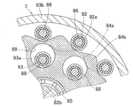
減速機7は、上記したようにサイクロイド減速機であり、図8のように外形がなだらかな波状のトロコイド曲線で形成された2枚の曲線板84a,84bが、それぞれ軸受85を介して回転入力軸82の各偏心部82a,82bに装着してある。これら各曲線板84a,84bの偏心運動を外周側で案内する複数の外ピン86を、それぞれハウジング83bに差し渡して設け、内方部材2のインボード側材60に取り付けた複数の内ピン88を、各曲線板84a,84bの内部に設けられた複数の円形の貫通孔89に挿入状態に係合させてある。回転入力軸82は、モータ6の回転出力軸74とスプライン結合されて一体に回転する。なお、回転入力軸82はインボード側のハウジング83aと内方部材52のインボード側材60の内径面とに2つの軸受90で両持ち支持されている。
モータ6の回転出力軸74が回転すると、これと一体回転する回転入力軸82に取り付けられた各曲線板84a,84bが偏心運動を行う。この各曲線板84a,84bの偏心運動が、内ピン88と貫通孔89との係合によって、内方部材52に回転運動として伝達される。回転出力軸74の回転に対して内方部材52の回転は減速されたものとなる。例えば、1段のサイクロイド減速機で1/10以上の減速比を得ることができる。
前記2枚の曲線板84a,84bは、互いに偏心運動が打ち消されるように180°位相をずらして回転入力軸82の各偏心部82a,82bに装着され、各偏心部82a,82bの両側には、各曲線板84a,84bの偏心運動による振動を打ち消すように、各偏心部82a,82bの偏心方向と逆方向へ偏心させたカウンターウエイト91が装着されている。
図9に拡大して示すように、前記各外ピン86と内ピン88には軸受92,93が装着され、これらの軸受92,93の外輪92a,93aが、それぞれ各曲線板84a,84bの外周と各貫通孔89の内周とに転接するようになっている。したがって、外ピン86と各曲線板84a,84bの外周との接触抵抗、および内ピン88と各貫通孔89の内周との接触抵抗を低減し、各曲線板84a,84bの偏心運動をスムーズに内方部材52に回転運動として伝達することができる。
図7において、モータ6は、円筒状のモータハウジング72に固定したモータステータ73と、回転出力軸74に取り付けたモータロータ75との間にラジアルギャップを設けたラジアルギャップ型のIPMモータである。回転出力軸74は、減速機7のインボード側のハウジング83aの筒部に2つの軸受76で片持ち支持されている。
モータステータ73は、軟質磁性体からなるステータコア部77とコイル78とでなる。ステータコア部77は、その外周面がモータハウジング72の内周面に嵌合して、モータハウジング72に保持されている。モータロータ75は、モータステータ73と同心に回転出力軸74に外嵌するロータコア部79と、このロータコア部79に内蔵される複数の永久磁石80とでなる。
モータ6には、モータステータ73とモータロータ75の間の相対回転角度を検出する角度センサ36が設けられる。角度センサ36は、モータステータ73とモータロータ75の間の相対回転角度を表す信号を検出して出力する角度センサ本体70と、この角度センサ本体70の出力する信号から角度を演算する角度演算回路71とを有する。
角度センサ本体70は、回転出力軸74の外周面に設けられる被検出部70aと、モータハウジング72に設けられ前記被検出部70aに例えば径方向に対向して近接配置される検出部70bとでなる。被検出部70aと検出部70bは軸方向に対向して近接配置されるものであっても良い。ここでは、各角度センサ36として、磁気エンコーダまたはレゾルバが用いられる。モータ6の回転制御は上記モータコントロール部29(図1,2)により行われる。このモータ6では、その効率を最大にするため、角度センサ36の検出するモータステータ73とモータロータ75の間の相対回転角度に基づき、モータステータ73のコイル78へ流す交流電流の各波の各相の印加タイミングを、モータコントロール部29のモータ駆動制御部33によってコントロールするようにされている。
なお、インホイールモータ駆動装置8のモータ電流の配線や各種センサ系,指令系の配線は、モータハウジング72等に設けられたコネクタ99により纏めて行われる。
図10は、図1,図2の回転センサ24の一例を示す。この回転センサ24は、車輪用軸受4における内方部材52の外周に設けられた磁気エンコーダ24aと、この磁気エンコーダ24aに対向して外方部材51に設けられた磁気センサ24bとでなる。磁気エンーダ24aは、円周方向に磁極N,Sを交互に着磁したリング状の部材である。この例では、回転センサ24は両列の転動体55,55間に配置しているが、車輪用軸受4の端部に設置しても良い。
なお、上記実施形態では、図1,2に示すように、ECU21とインバータ装置22とを離して設けたが、ECU21とインバータ装置22とは同じコンピュータで構成されていても良い。
以上のとおり、図面を参照しながら好適な実施形態を説明したが、当業者であれば、本件明細書を見て、自明な範囲内で種々の変更および修正を容易に想定するであろう。したがって、そのような変更および修正は、請求の範囲から定まる発明の範囲内のものと解釈される。
1…車体
2,3…車輪
4…車輪用軸受
6…モータ
7…減速機
8…インホイールモータ駆動装置
9,10…機械式のブレーキ
21…ECU
22…インバータ装置
24…回転センサ
28…パワー回路部
29…モータコントロール部
30…インホイールモータユニット
31…インバータ
32…PWMドライバ
33…モータ駆動制御部
34…モータ誤動作チェック・コントロール手段
35…電流センサ
36…角度センサ
37…誤動作検出手段
38…誤動作対応制御手段
41…回転方向指示判別部
42…回転方向異常判定部
43…回転数推定部
44…回転数異常判定部
45…モータ電流推定部
46…電流異常判定部
47…異常報告手段
Claims (9)
- 車輪を駆動するモータと、車両全般を制御する電気制御ユニットであるECUと、バッテリの直流電力を前記モータの駆動に用いる交流電力に変換するインバータを含むパワー回路部および前記ECUから与えられるトルク指令に従って前記パワー回路部を制御するモータコントロール部を有するインバータ装置と、車輪を制動する機械式ブレーキとを備えた電気自動車であって、
前記ECUの出力する前記トルク指令と、前記モータまたはこのモータで駆動される車輪の回転信号、回転方向信号、およびモータ電流のいずれかを常時監視し、この監視した情報を基に、定められた規則に従ってモータの誤動作を検出する誤動作検出手段と、
この誤動作検出手段で誤動作が検出されると前記モータへの駆動電流の停止、および前記機械式ブレーキによる制動のいずれかまたは両方を行わせる誤動作対応制御手段とを設けた、
電気自動車。 - 請求項1において、前記誤動作検出手段は、前記ECUから与えられるトルク指令よりモータの回転すべき回転方向を判定する回転方向指示判別部と、前記モータまたはこのモータで駆動される車輪の回転信号、回転方向信号、およびモータ電流のいずれかから得られる回転方向とを比較してモータの回転方向異常を判定する回転方向異常判定部とを有する電気自動車。
- 請求項1において、前記誤動作検出手段は、前記ECUから与えられるトルク指令よりモータの回転すべき回転数を判定する回転数推定部と、前記モータまたはこのモータで駆動される車輪の回転信号とを比較してモータの回転数異常を判定する回転数異常判定部とを有する電気自動車。
- 請求項1において、それぞれ別の車輪を駆動する複数のモータを備え、前記誤動作対応制御手段は、一つのモータの誤動作を検出したときに、その誤動作が検出されたモータへの駆動電流の停止と、他のモータへの駆動電流の停止とを行わせる電気自動車。
- 請求項1において、前記誤動作検出手段および前記誤動作対応制御手段を前記インバータ装置に設けた電気自動車。
- 請求項1において、一つのモータに対して前記誤動作検出手段を2つ設け、前記誤動作対応制御手段は、2つの誤動作検出手段の両方が誤動作を検出した場合にのみに前記モータへの駆動電流の停止、または前記機械式ブレーキによる制動の制御である誤動作対応制御を行わせるか、またはいずれか一方の誤動作検出手段が誤動作を検出した場合に、前記誤動作対応制御を行わせるものとした電気自動車。
- 請求項1において、一つのモータに対して前記誤動作検出手段を3つ以上設け、前記誤動作対応制御手段は、前記3つ以上の誤動作検出手段のうちの過半数が誤動作を検出した場合に、前記モータへの駆動電流の停止、または前記機械式ブレーキによる制動の制御である誤動作対応制御を行わせるものとした電気自動車。
- 請求項1において、前記モータは、車輪用軸受と、この車輪用軸受とモータの間に介在した減速機とを有するインホイールモータ駆動装置を構成する電気自動車。
- 請求項8において、前記減速機はサイクロイド減速機である電気自動車。
Priority Applications (3)
| Application Number | Priority Date | Filing Date | Title |
|---|---|---|---|
| CN201280009937.4A CN103384614B (zh) | 2011-02-25 | 2012-02-10 | 电动汽车 |
| EP12749902.8A EP2679433B1 (en) | 2011-02-25 | 2012-02-10 | Electric automobile |
| US13/985,925 US8909406B2 (en) | 2011-02-25 | 2012-02-10 | Electric automobile |
Applications Claiming Priority (2)
| Application Number | Priority Date | Filing Date | Title |
|---|---|---|---|
| JP2011039412A JP5657426B2 (ja) | 2011-02-25 | 2011-02-25 | 電気自動車 |
| JP2011-039412 | 2011-02-25 |
Publications (1)
| Publication Number | Publication Date |
|---|---|
| WO2012114899A1 true WO2012114899A1 (ja) | 2012-08-30 |
Family
ID=46720683
Family Applications (1)
| Application Number | Title | Priority Date | Filing Date |
|---|---|---|---|
| PCT/JP2012/053058 Ceased WO2012114899A1 (ja) | 2011-02-25 | 2012-02-10 | 電気自動車 |
Country Status (5)
| Country | Link |
|---|---|
| US (1) | US8909406B2 (ja) |
| EP (1) | EP2679433B1 (ja) |
| JP (1) | JP5657426B2 (ja) |
| CN (1) | CN103384614B (ja) |
| WO (1) | WO2012114899A1 (ja) |
Cited By (1)
| Publication number | Priority date | Publication date | Assignee | Title |
|---|---|---|---|---|
| CN110546051A (zh) * | 2017-04-28 | 2019-12-06 | 维宁尔美国公司 | 用于与制动助力器子系统相关联的马达的动态制动的系统和方法 |
Families Citing this family (18)
| Publication number | Priority date | Publication date | Assignee | Title |
|---|---|---|---|---|
| US9027682B2 (en) * | 2013-02-01 | 2015-05-12 | Daniel James LAMBERT | Self charging electric vehicle |
| JP6318909B2 (ja) | 2014-06-25 | 2018-05-09 | 三菱自動車工業株式会社 | ハイブリッド車両の制御装置 |
| DE102015200122B4 (de) * | 2015-01-08 | 2016-11-03 | Robert Bosch Gmbh | Verfahren und Vorrichtung zum Betreiben eines Kraftfahrzeugs mit einer Sicherheitseinrichtung zur Kompensation fehlerhafter Drehmomente |
| JP5963904B1 (ja) * | 2015-04-14 | 2016-08-03 | 三菱電機株式会社 | ハイブリッド車両の制御装置および制御方法 |
| CN106608250B (zh) * | 2015-10-26 | 2019-03-29 | 比亚迪股份有限公司 | 车辆的主动安全控制系统和方法 |
| JP6875909B2 (ja) * | 2017-03-30 | 2021-05-26 | 住友重機械工業株式会社 | モータのコントローラおよび射出成形機 |
| KR102334659B1 (ko) * | 2017-06-29 | 2021-12-03 | 현대모비스 주식회사 | 인휠 구동 시스템의 고장 검출 장치 및 방법 |
| JP6757503B2 (ja) * | 2017-08-24 | 2020-09-23 | 株式会社オートネットワーク技術研究所 | 電源システム及び電気自動車 |
| CN109510390B (zh) * | 2017-09-15 | 2021-07-09 | 日本电产株式会社 | 驱动装置 |
| CN109510364B (zh) * | 2017-09-15 | 2021-04-16 | 日本电产株式会社 | 驱动装置 |
| KR102485340B1 (ko) * | 2017-12-08 | 2023-01-05 | 현대자동차주식회사 | 전기동력 차량 주행 방향 제어 장치, 그를 포함한 시스템 및 그 방법 |
| KR102563435B1 (ko) * | 2018-10-01 | 2023-08-03 | 현대자동차 주식회사 | 차량 시스템, 차량의 모터 제어 시스템 및 그 방법 |
| JP7278201B2 (ja) * | 2019-11-27 | 2023-05-19 | 日立Astemo株式会社 | 車両制御システム |
| GB2596185B (en) * | 2020-04-15 | 2024-07-17 | Benedex Ltd | Drive system |
| CN114906116B (zh) * | 2021-07-16 | 2024-10-29 | 株式会社电装 | 驻车控制装置及驻车控制方法 |
| DE102022212044A1 (de) * | 2022-11-14 | 2024-05-16 | Zf Friedrichshafen Ag | Verfahren zum Unterbinden eines ungewollten Fahrens einer Arbeitsmaschine in eine falsche Richtung |
| CN116653626A (zh) * | 2023-05-24 | 2023-08-29 | 东风汽车集团股份有限公司 | 轮毂电机驱动车辆的控制系统、控制方法及车辆 |
| US12589789B2 (en) | 2023-08-15 | 2026-03-31 | Benedex Ltd | Mobile platform and method of assembly thereof |
Citations (7)
| Publication number | Priority date | Publication date | Assignee | Title |
|---|---|---|---|---|
| JPH07298418A (ja) * | 1994-04-19 | 1995-11-10 | Shikoku Electric Power Co Inc | 電気自動車 |
| JP2000134703A (ja) * | 1998-10-29 | 2000-05-12 | Hitachi Ltd | 車上情報制御装置 |
| JP2004215350A (ja) * | 2002-12-27 | 2004-07-29 | Sony Corp | 駆動制御装置およびその方法と2輪車 |
| JP2005328680A (ja) * | 2004-05-17 | 2005-11-24 | Toyota Motor Corp | 四輪独立制駆動車輌の走行制御装置 |
| JP2006258289A (ja) * | 2005-02-16 | 2006-09-28 | Ntn Corp | インホイールモータ駆動装置 |
| JP2008092708A (ja) * | 2006-10-03 | 2008-04-17 | Hitachi Ltd | モータ駆動制御装置 |
| JP2008172935A (ja) | 2007-01-12 | 2008-07-24 | Ntn Corp | インホイールモータ駆動装置 |
Family Cites Families (11)
| Publication number | Priority date | Publication date | Assignee | Title |
|---|---|---|---|---|
| DE19502501C2 (de) * | 1995-01-27 | 2000-11-30 | Mannesmann Sachs Ag | Sicherheitsschaltung für Kfz mit Elektrotraktion |
| JP2002112479A (ja) * | 2000-09-27 | 2002-04-12 | Yaskawa Electric Corp | 永久磁石モータとその制御方法 |
| JP2003125588A (ja) * | 2001-10-12 | 2003-04-25 | Mitsubishi Electric Corp | 電力変換装置 |
| JP3555617B2 (ja) * | 2002-09-04 | 2004-08-18 | 日産自動車株式会社 | 車両の駆動力制御装置 |
| JP2006189371A (ja) * | 2005-01-07 | 2006-07-20 | Mitsubishi Electric Corp | 車両用速度検出装置 |
| JP4443457B2 (ja) * | 2005-04-11 | 2010-03-31 | 日立オートモティブシステムズ株式会社 | パワーステアリング装置 |
| JP2006331013A (ja) * | 2005-05-25 | 2006-12-07 | Yaskawa Electric Corp | サーボ制御装置と制御方法 |
| US8025345B2 (en) * | 2007-03-27 | 2011-09-27 | Advics Co., Ltd. | Vehicle brake system |
| US8475315B2 (en) * | 2010-02-15 | 2013-07-02 | Jtekt Corporation | Swing internal contact type planetary gear device and rotation drive device |
| JP5808923B2 (ja) * | 2011-03-18 | 2015-11-10 | Ntn株式会社 | モータ駆動装置及び電気自動車 |
| KR101278914B1 (ko) * | 2012-01-09 | 2013-06-26 | 주식회사 만도 | 인휠 모터 시스템의 장착 구조체 |
-
2011
- 2011-02-25 JP JP2011039412A patent/JP5657426B2/ja not_active Expired - Fee Related
-
2012
- 2012-02-10 US US13/985,925 patent/US8909406B2/en active Active
- 2012-02-10 CN CN201280009937.4A patent/CN103384614B/zh not_active Expired - Fee Related
- 2012-02-10 WO PCT/JP2012/053058 patent/WO2012114899A1/ja not_active Ceased
- 2012-02-10 EP EP12749902.8A patent/EP2679433B1/en active Active
Patent Citations (7)
| Publication number | Priority date | Publication date | Assignee | Title |
|---|---|---|---|---|
| JPH07298418A (ja) * | 1994-04-19 | 1995-11-10 | Shikoku Electric Power Co Inc | 電気自動車 |
| JP2000134703A (ja) * | 1998-10-29 | 2000-05-12 | Hitachi Ltd | 車上情報制御装置 |
| JP2004215350A (ja) * | 2002-12-27 | 2004-07-29 | Sony Corp | 駆動制御装置およびその方法と2輪車 |
| JP2005328680A (ja) * | 2004-05-17 | 2005-11-24 | Toyota Motor Corp | 四輪独立制駆動車輌の走行制御装置 |
| JP2006258289A (ja) * | 2005-02-16 | 2006-09-28 | Ntn Corp | インホイールモータ駆動装置 |
| JP2008092708A (ja) * | 2006-10-03 | 2008-04-17 | Hitachi Ltd | モータ駆動制御装置 |
| JP2008172935A (ja) | 2007-01-12 | 2008-07-24 | Ntn Corp | インホイールモータ駆動装置 |
Cited By (1)
| Publication number | Priority date | Publication date | Assignee | Title |
|---|---|---|---|---|
| CN110546051A (zh) * | 2017-04-28 | 2019-12-06 | 维宁尔美国公司 | 用于与制动助力器子系统相关联的马达的动态制动的系统和方法 |
Also Published As
| Publication number | Publication date |
|---|---|
| JP5657426B2 (ja) | 2015-01-21 |
| US20130325239A1 (en) | 2013-12-05 |
| EP2679433B1 (en) | 2020-01-22 |
| EP2679433A1 (en) | 2014-01-01 |
| JP2012178904A (ja) | 2012-09-13 |
| CN103384614B (zh) | 2015-08-12 |
| CN103384614A (zh) | 2013-11-06 |
| US8909406B2 (en) | 2014-12-09 |
| EP2679433A4 (en) | 2017-07-19 |
Similar Documents
| Publication | Publication Date | Title |
|---|---|---|
| JP5657426B2 (ja) | 電気自動車 | |
| JP5784930B2 (ja) | 電気自動車 | |
| JP5705585B2 (ja) | 電気自動車 | |
| JP5886008B2 (ja) | 電気自動車のモータ制御装置 | |
| JP5657425B2 (ja) | 電気自動車 | |
| JP5832868B2 (ja) | 電気自動車 | |
| JP5936306B2 (ja) | 電気自動車 | |
| WO2012114902A1 (ja) | 電気自動車 | |
| WO2012114901A1 (ja) | 電気自動車、インホイールモータ駆動装置およびモータ制御方法 | |
| JP5731233B2 (ja) | 電気自動車 | |
| JP5735305B2 (ja) | 電気自動車 | |
| JP5731593B2 (ja) | 電気自動車 | |
| JP5781326B2 (ja) | 電気自動車 | |
| JP5731234B2 (ja) | 電気自動車 | |
| JP5805406B2 (ja) | インホイールモータ駆動装置 | |
| JP5985724B2 (ja) | 電気自動車 | |
| JP5829497B2 (ja) | 電気自動車のモータ制御装置 |
Legal Events
| Date | Code | Title | Description |
|---|---|---|---|
| 121 | Ep: the epo has been informed by wipo that ep was designated in this application |
Ref document number: 12749902 Country of ref document: EP Kind code of ref document: A1 |
|
| WWE | Wipo information: entry into national phase |
Ref document number: 13985925 Country of ref document: US |
|
| NENP | Non-entry into the national phase |
Ref country code: DE |
|
| WWE | Wipo information: entry into national phase |
Ref document number: 2012749902 Country of ref document: EP |