WO2012114913A1 - 建設機械の作動油タンク - Google Patents
建設機械の作動油タンク Download PDFInfo
- Publication number
- WO2012114913A1 WO2012114913A1 PCT/JP2012/053150 JP2012053150W WO2012114913A1 WO 2012114913 A1 WO2012114913 A1 WO 2012114913A1 JP 2012053150 W JP2012053150 W JP 2012053150W WO 2012114913 A1 WO2012114913 A1 WO 2012114913A1
- Authority
- WO
- WIPO (PCT)
- Prior art keywords
- hydraulic oil
- oil tank
- gauge
- construction machine
- hydraulic
- Prior art date
- Legal status (The legal status is an assumption and is not a legal conclusion. Google has not performed a legal analysis and makes no representation as to the accuracy of the status listed.)
- Ceased
Links
Images






Classifications
-
- F—MECHANICAL ENGINEERING; LIGHTING; HEATING; WEAPONS; BLASTING
- F15—FLUID-PRESSURE ACTUATORS; HYDRAULICS OR PNEUMATICS IN GENERAL
- F15B—SYSTEMS ACTING BY MEANS OF FLUIDS IN GENERAL; FLUID-PRESSURE ACTUATORS, e.g. SERVOMOTORS; DETAILS OF FLUID-PRESSURE SYSTEMS, NOT OTHERWISE PROVIDED FOR
- F15B1/00—Installations or systems with accumulators; Supply reservoir or sump assemblies
- F15B1/26—Supply reservoir or sump assemblies
-
- E—FIXED CONSTRUCTIONS
- E02—HYDRAULIC ENGINEERING; FOUNDATIONS; SOIL SHIFTING
- E02F—DREDGING; SOIL-SHIFTING
- E02F3/00—Dredgers; Soil-shifting machines
- E02F3/04—Dredgers; Soil-shifting machines mechanically-driven
- E02F3/28—Dredgers; Soil-shifting machines mechanically-driven with digging tools mounted on a dipper- or bucket-arm, i.e. there is either one arm or a pair of arms, e.g. dippers, buckets
- E02F3/30—Dredgers; Soil-shifting machines mechanically-driven with digging tools mounted on a dipper- or bucket-arm, i.e. there is either one arm or a pair of arms, e.g. dippers, buckets with a dipper-arm pivoted on a cantilever beam, i.e. boom
- E02F3/32—Dredgers; Soil-shifting machines mechanically-driven with digging tools mounted on a dipper- or bucket-arm, i.e. there is either one arm or a pair of arms, e.g. dippers, buckets with a dipper-arm pivoted on a cantilever beam, i.e. boom working downwardly and towards the machine, e.g. with backhoes
- E02F3/325—Backhoes of the miniature type
-
- E—FIXED CONSTRUCTIONS
- E02—HYDRAULIC ENGINEERING; FOUNDATIONS; SOIL SHIFTING
- E02F—DREDGING; SOIL-SHIFTING
- E02F9/00—Component parts of dredgers or soil-shifting machines, not restricted to one of the kinds covered by groups E02F3/00 - E02F7/00
- E02F9/08—Superstructures; Supports for superstructures
- E02F9/0858—Arrangement of component parts installed on superstructures not otherwise provided for, e.g. electric components, fenders, air-conditioning units
- E02F9/0883—Tanks, e.g. oil tank, urea tank, fuel tank
-
- E—FIXED CONSTRUCTIONS
- E02—HYDRAULIC ENGINEERING; FOUNDATIONS; SOIL SHIFTING
- E02F—DREDGING; SOIL-SHIFTING
- E02F9/00—Component parts of dredgers or soil-shifting machines, not restricted to one of the kinds covered by groups E02F3/00 - E02F7/00
- E02F9/26—Indicating devices
-
- G—PHYSICS
- G01—MEASURING; TESTING
- G01F—MEASURING VOLUME, VOLUME FLOW, MASS FLOW OR LIQUID LEVEL; METERING BY VOLUME
- G01F9/00—Measuring volume flow relative to another variable, e.g. of liquid fuel for an engine
-
- Y—GENERAL TAGGING OF NEW TECHNOLOGICAL DEVELOPMENTS; GENERAL TAGGING OF CROSS-SECTIONAL TECHNOLOGIES SPANNING OVER SEVERAL SECTIONS OF THE IPC; TECHNICAL SUBJECTS COVERED BY FORMER USPC CROSS-REFERENCE ART COLLECTIONS [XRACs] AND DIGESTS
- Y10—TECHNICAL SUBJECTS COVERED BY FORMER USPC
- Y10T—TECHNICAL SUBJECTS COVERED BY FORMER US CLASSIFICATION
- Y10T137/00—Fluid handling
- Y10T137/8158—With indicator, register, recorder, alarm or inspection means
Definitions
- the present invention relates to a hydraulic oil tank for a construction machine that is provided in a construction machine such as a small excavator and has a gauge that enables visual confirmation of the oil level of the hydraulic oil.
- the construction machine is often provided with an iron hydraulic oil tank, that is, an iron hydraulic oil tank that stores pressure oil supplied to the hydraulic actuator described above, from the viewpoint of ensuring strength.
- an iron hydraulic oil tank that is, an iron hydraulic oil tank that stores pressure oil supplied to the hydraulic actuator described above, from the viewpoint of ensuring strength.
- a hydraulic oil tank is placed together with an engine, a hydraulic pump, a control valve, a turning motor, etc. in a very small equipment arrangement space on a revolving structure like a small excavator, it is easy to form a complicated shape.
- a hydraulic oil tank made of synthetic resin may be provided.
- Such a hydraulic oil tank made of synthetic resin does not require painting and rust prevention treatment, is lighter than an iron hydraulic oil tank, is light in weight, and hardly transfers the heat of the hydraulic oil contained inside to the outside.
- Such a hydraulic oil tank made of synthetic resin is arranged so that its side faces the exterior cover of the swivel body, but in order to prevent interference and contact with the exterior cover due to shaking of the vehicle body, it is usually attached to the exterior cover. On the other hand, it is arranged with a predetermined clearance. Further, the hydraulic oil tank is provided with a gauge made of a transparent body that enables visual confirmation of the oil level of the hydraulic oil accommodated therein through a hole formed in the exterior cover. The visual check of the hydraulic oil level through such a gauge is intended to know whether the amount of hydraulic oil stored in the hydraulic oil tank has decreased with long-term operation. When the hydraulic oil in the oil tank becomes less than the allowable value, for example, replacement work of the hydraulic oil in the hydraulic oil tank is performed.
- a hydraulic oil tank made of this type of synthetic resin is disclosed in Patent Document 1, for example.
- the above-described hydraulic oil tank made of synthetic resin is weaker than that of iron.
- the hydraulic oil level in the hydraulic oil tank fluctuates due to work performed on the construction machine or the like, or the hydraulic actuator (hydraulic cylinder, hydraulic motor) is used.
- the hydraulic actuator hydraulic cylinder, hydraulic motor
- the gauge installation part is deformed, and when checking the oil level of the hydraulic oil in the hydraulic oil tank from the gauge through the hole in the exterior cover, it may be difficult to check the position of the oil level. . That is, there is a risk that visibility may be reduced in the conventional technique.
- the gauge is provided in the hole of the outer cover. From this point, it is difficult to visually check the position of the oil level in the hydraulic oil tank, and the visibility cannot be improved.
- the present invention provides a revolving body having an outer cover, a working device attached to the revolving body, a turning motor for driving the revolving body, and a hydraulic actuator including an actuator for driving the working device.
- a construction machine having a hydraulic oil tank made of synthetic resin, the hydraulic oil tank having a gauge that allows visual confirmation of the oil level of the hydraulic oil in the hydraulic oil tank through a hole formed in the exterior cover.
- the gauge is provided on the side surface of the hydraulic oil tank, and is directed toward the hole of the exterior cover.
- a projecting portion having a hollow inside, and a window portion made of a transparent body provided at an end portion of the projecting portion and enabling visual confirmation of the oil level of the working oil in the working oil tank. It is characterized by.
- the gauge since the gauge has a protruding portion that is formed to protrude from the side surface of the hydraulic oil tank, the strength of the gauge arrangement portion can be ensured. As a result, deformation of the gauge arrangement part due to the fluctuation of the oil level of the hydraulic oil in the hydraulic oil tank due to work performed by the work device or due to the up and down of the oil level due to the usage of the hydraulic actuator. Can be suppressed. Therefore, when visually checking the position of the oil level of the hydraulic oil in the hydraulic oil tank from the gauge window through the hole in the outer cover, the position of the oil level is accurately confirmed via a gauge that has not been deformed. Can be done.
- the window portion of the gauge protrudes in the direction of the hole portion of the exterior cover and the window portion is provided at the end of the projection portion, a predetermined clearance is provided between the exterior cover and the hydraulic oil tank.
- the hydraulic oil in the hydraulic oil tank can be guided to the window portion close to the hole portion of the outer cover by the protruding portion of the cavity, and from the gauge window portion to the inner portion of the hydraulic oil tank through the hole portion of the outer cover.
- the hole portion of the outer cover can be covered with the window portion of the gauge by bringing the window portion of the gauge closer to the hole portion of the outer cover. Therefore, it is possible to suppress the intrusion of rainwater or the like from the hole portion of the exterior cover into the swivel body.
- the present invention is characterized in that, in the above-mentioned invention, the protruding portion of the gauge has a frustoconical outer diameter shape.
- the present invention configured as described above can reduce the space near the hole of the outer cover in the swivel body by the outer surface of the projecting portion, and is effective in suppressing intrusion of rainwater and the like.
- the present invention is characterized in that, in the above invention, the window portion of the gauge is positioned in the hole portion of the exterior cover.
- the present invention configured as described above can block most of the hole portion of the exterior cover with the window portion of the gauge, and is effective in suppressing intrusion of rainwater and the like.
- the present invention is characterized in that, in the above-mentioned invention, the construction machine is composed of a small excavator of a turning type within the rear end vehicle width.
- the strength of the gauge arrangement portion can be ensured by the formation of the protruding portion, and the oil level of the oil level caused by the fluctuation of the level of the hydraulic oil stored in the hydraulic oil tank or the usage of the hydraulic actuator can be secured. It is possible to suppress deformation of the gauge arrangement portion due to up and down. Further, according to the present invention, the hydraulic oil in the hydraulic oil tank can be guided to the window portion by the protruding portion of the cavity. That is, according to the present invention, it is possible to ensure the strength of the gauge arrangement portion and to bring the gauge closer to the hole of the outer cover while maintaining a predetermined clearance between the outer cover and the hydraulic oil tank. it can.
- the present invention makes it easier to see the oil level when visually checking the position of the oil level in the hydraulic oil tank from the gauge window through the hole in the exterior cover. It can be performed accurately and easily, and the visibility of the hydraulic oil with respect to the oil level can be improved as compared with the prior art. Moreover, infiltration of rainwater or the like from the hole portion of the outer cover can be suppressed, and the sealing performance for the hole portion of the outer cover can be improved as compared with the conventional case.
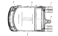
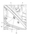
- FIG. 1 It is the principal part side view of the small shovel mentioned as an example of the construction machine provided with the hydraulic oil tank which concerns on this invention. It is A sectional expanded view of FIG. It is a principal part top view of the small shovel shown in FIG. It is a principal part top view which shows the state except the cab from the state shown in FIG. It is a principal part perspective view which shows the state except the cab of the small shovel shown in FIG. It is a principal part enlarged view of FIG. It is a perspective view showing the hydraulic oil tank concerning this embodiment in the state where hydraulic oil is stored. It is a figure which shows the hydraulic oil tank which concerns on this embodiment in the state in which hydraulic oil is accommodated, (a) A figure is a top view, (b) A figure is a front view, (c) A figure is a side view.
- the construction machine provided with the hydraulic oil tank according to the present embodiment is composed of, for example, a small-sized excavator of the rear end vehicle width turning type that has a narrow arrangement area of various devices and is easily restricted by the arrangement of the hydraulic oil tank.
- the small excavator includes a traveling body 1 and a revolving body 2 disposed on the traveling body 1.
- a cab 3 is arranged on the revolving structure 2.
- a working device (not shown) is attached to the working device mounting portion 4.
- the working device includes, for example, hydraulic actuators such as a boom, an arm, a bucket, a boom cylinder, an arm cylinder, and a bucket cylinder, and performs soil excavation work and the like.
- the small excavator also includes a hydraulic motor such as a traveling motor that causes the traveling body 1 to travel and a turning motor that causes the revolving body 2 to rotate.
- the hydraulic oil tank 6 is made of synthetic resin, and is provided on the swivel frame 2a of the swivel body 2 as shown in FIGS. 4, 5 and 6, and as shown in FIG.
- the exterior cover 5 of the body 2 has a side surface 6a that is opposed to the exterior cover 5 with a predetermined clearance 20, and stores hydraulic oil supplied to the hydraulic actuator described above.
- the hydraulic oil tank 6 has a visual observation of the oil level 8 of the hydraulic oil in the hydraulic oil tank 6 through a hole 5 a formed in the exterior cover 5 of the swivel body 2. It has a gauge 7 that enables confirmation.
- the hydraulic oil tank 6 has, for example, a basic outer diameter shape formed in a rectangular parallelepiped shape, and a belt-like uneven portion 6b formed in the central portion. The overall strength of the hydraulic oil tank 6 made of synthetic resin is secured by the uneven portion 6b.
- the hydraulic oil tank 6 is provided with a filter 10 that filters the hydraulic oil and keeps it clean, and a return that is provided at the position of the filter 10 and guides the return oil from the hydraulic actuator. It has a connection part 9 to which a pipe is connected, a connection part 11 to which a drain pipe is connected, and a connection part 12 to which a supply pipe for supplying hydraulic oil to a hydraulic pump (not shown) is connected.
- the gauge 7 of the hydraulic oil tank 6 is provided on the side surface 6a of the hydraulic oil tank 6a opposite to the outer cover 5 and protrudes toward the hole 5a of the outer cover 5 as shown in FIGS.
- the protruding portion 7a of the gauge 7 has, for example, a frustoconical outer diameter shape. Further, as shown in FIG. 2, the window portion 7 b of the gauge 7 is positioned in the hole portion 5 a of the exterior cover 5, for example.
- the amount of the hydraulic oil accommodated therein during the work performed by the working device performed for a long time is That is, a visual check is performed to determine whether or not the position of the oil surface 8 of the hydraulic oil is within an allowable value.
- This visual confirmation is performed by visually confirming the position of the oil surface 8 of the hydraulic oil stored in the hydraulic oil tank 6 from the window 7b of the gauge 7 through the hole 5a of the outer cover 5.
- the gauge 7 since the gauge 7 has the protruding portion 7a, an uneven portion can be formed on the side surface 6a of the flat hydraulic oil tank 6, and thereby the gauge 7 The strength of the arrangement portion can be ensured. As a result, the gauge 7 is moved by the fluctuation of the oil level 8 of the hydraulic oil in the hydraulic oil tank 6 due to work performed by a working device (not shown) or by the up and down of the oil level when the hydraulic actuator is used. Deformation of the arrangement portion can be suppressed. Moreover, according to this embodiment, the hydraulic oil in the hydraulic oil tank 6 can be guide
- the strength of the portion where the gauge 7 is disposed can be ensured, and the gauge 7 is attached to the exterior cover with a predetermined clearance 20 between the exterior cover 5 and the hydraulic oil tank 6. 5 holes 5a.
- this embodiment becomes easy to see the oil level 8 when visually confirming the position of the oil level 8 of the hydraulic oil in the hydraulic oil tank 6 from the window part 7b of the gauge 7 through the hole 5a of the exterior cover 5.
- the position of the oil level 8 can be confirmed accurately and easily, and the visibility of the hydraulic oil to the oil level 8 can be improved.
- the hole portion 5a of the outer cover 5 can be covered by the window portion 7b of the gauge 7.
- the window portion 7b of the gauge 7 since the outer diameter shape of the protruding portion 7a is formed in a frustoconical shape, as shown in FIG. 2, the space portion in the vicinity of the hole 5a of the outer cover 5 in the swivel body 2 is formed. The outer surface of the protruding portion 7a can be reduced. This is effective in suppressing the intrusion of rainwater and the like.
Landscapes
- Engineering & Computer Science (AREA)
- General Engineering & Computer Science (AREA)
- Mining & Mineral Resources (AREA)
- Civil Engineering (AREA)
- Structural Engineering (AREA)
- Mechanical Engineering (AREA)
- Physics & Mathematics (AREA)
- Fluid Mechanics (AREA)
- General Physics & Mathematics (AREA)
- Supply Devices, Intensifiers, Converters, And Telemotors (AREA)
- Component Parts Of Construction Machinery (AREA)
Abstract
【課題】ゲージ配設部分の強度を確保でき、外装カバーと当該作動油タンクとの間に所定のクリアランスを保った状態で、ゲージを外装カバーの穴部に近づけることができる。 【解決手段】本発明は、小型の油圧ショベルに備えられる旋回体2の旋回フレーム2a上に設けられ、旋回体2の外装カバー5に所定のクリアランス20をもって対向する側面6aを有し、油圧アクチュエータに供給される作動油が蓄えられる合成樹脂から成る作動油タンク6であって、この作動油タンク6が、外装カバー5に形成した穴部5aを通しての作動油タンク6内の作動油の油面8の目視確認を可能にするゲージ7を有し、このゲージ7が、当該作動油タンク6の側面6aに設けられ、外装カバー5の穴部5a方向に突出形成され、内部が空洞の突出部7aと、この突出部7aの端部に設けられ、作動油タンク6内の作動油の油面8の目視確認を可能にする透明体から成る窓部7bとを有している。
Description
本発明は、小型ショベル等の建設機械に設けられ、作動油の油面の目視確認を可能にするゲージを有する建設機械の作動油タンクに関する。
外装カバーを有する旋回体と、この旋回体に取り付けられるブーム、アーム、バケット等を含む作業装置と、旋回体を駆動する旋回モータ及び作業装置を駆動するアクチュエータを含む油圧アクチュエータとを有する油圧ショベル等の建設機械にあっては、一般に、強度確保の観点から鉄製の作動油タンク、すなわち上述した油圧アクチュエータに供給される圧油が蓄えられる鉄製の作動油タンクが設けられことが多い。しかし、小型ショベルのように、旋回体上の極めて狭い機器配置スペースに、エンジン、油圧ポンプ、コントロールバルブ、旋回モータなどとともに作動油タンクを配置するような場合には、複雑な形状に形成しやすいことから合成樹脂製の作動油タンクが設けられることがある。このような合成樹脂製の作動油タンクは、鉄製の作動油タンクに比べて、塗装、防錆処理が不要であり、軽量であり、また内部に収容された作動油の熱を外部に伝えにくい利点がある。
このような合成樹脂製の作動油タンクは、その側面が旋回体の外装カバーに対向するように配置されるが、車体の揺れ等による外装カバーとの干渉、接触を防ぐために通常、外装カバーに対して所定のクリアランスをもって配置される。また、この作動油タンクは、外装カバーに形成した穴部を通しての、内部に収容した作動油の油面の目視確認を可能にする透明体から成るゲージが設けられている。このようなゲージを介しての作動油の油面の目視確認は、作動油タンクに収容した作動油の量が長時間の稼働に伴って少なくなってきたかどうかを知るためのものであり、作動油タンク内の作動油が許容値よりも少なくなってきたときには、例えば作動油タンク内の作動油の交換作業などが行われる。なお、この種の合成樹脂製の作動油タンクは、例えば特許文献1に開示されている。
ところで、上述した合成樹脂製の作動油タンクは、鉄製のものに比べて強度が弱い。このため、従来の作動油タンクでは、当該建設機械で実施される作業等によって作動油タンク内の作動油の油面が揺れることにより、あるいは油圧アクチュエータ(油圧シリンダ、油圧モータ)の使われかたに伴って油面が上下することにより、作動油タンク内が加圧、減圧されて作動油タンクが変形する懸念がある。これに伴って、ゲージ配設部分が変形し、外装カバーの穴部を通してゲージから作動油タンク内の作動油の油面を目視確認する際に、油面の位置を確認しずらいことがある。すなわち、従来技術では視認性が低下する恐れがある。
また、従来の作動油タンクでは、外装カバーと作動油タンクの側面との間に干渉防止等のために所定のクリアランスをもって当該作動油タンクが配置されているので、ゲージが、外装カバーの穴部から上述のクリアランスに相応する距離離れて位置する状態にあり、この点でも作動油タンク内の油面の位置の目視確認が難しくなりやすく、視認性の向上を見込めない。
さらに、従来の作動油タンクでは、外装カバーとゲージとの間に、すなわち外装カバーの穴部とゲージとの間に、上述の所定のクリアランスに相当する空間部が形成されることから、雨水等が外装カバーの穴部及び上述の空間部を通して外装カバーの内側に、すなわち旋回体の内部に浸入する懸念がある。すなわち、シール性の点でも問題があった。
本発明は、上述した従来技術における実状からなされたもので、その目的は、ゲージ配設部分の強度を確保することができるとともに、外装カバーと当該作動油タンクとの間に所定のクリアランスを保った状態で、ゲージを外装カバーの穴部に近づけることができる建設機械の作動油タンクを提供することにある。
この目的を達成するために、本発明は、外装カバーを有する旋回体と、この旋回体に取り付けられる作業装置と、上記旋回体を駆動する旋回モータ及び上記作業装置を駆動するアクチュエータを含む油圧アクチュエータとを有する建設機械に備えられ、上記旋回体の旋回フレーム上に設けられ、上記旋回体の外装カバーに所定のクリアランスをもって対向する側面を有し、上記油圧アクチュエータに供給される作動油が蓄えられる合成樹脂から成る作動油タンクであって、この作動油タンクが、上記外装カバーに形成した穴部を通しての上記作動油タンク内の作動油の油面の目視確認を可能にするゲージを有する建設機械の作動油タンクにおいて、上記ゲージが、当該作動油タンクの上記側面に設けられ、上記外装カバーの上記穴部方向に突出形成され、内部が空洞の突出部と、この突出部の端部に設けられ、上記作動油タンク内の作動油の油面の目視確認を可能にする透明体から成る窓部とを有することを特徴としている。
このように構成した本発明は、ゲージが、当該作動油タンクの側面に突出形成される突出部を有することから、このゲージ配設部分の強度を確保することができる。これにより、作業装置によって実施される作業等に伴う当該作動油タンク内の作動油の油面の揺れによる、あるいは油圧アクチュエータの使われかたに伴う油面の上下によるゲージ配設部分の変形を抑えることができる。したがって、外装カバーの穴部を通してゲージの窓部から作動油タンク内の作動油の油面の位置を目視確認する際に、この油面の位置の確認を変形を生じていないゲージを介して正確に行うことができる。また、本発明は、ゲージの窓部が外装カバーの穴部方向に突出し、この突出部の端部に窓部を設けてあることから、外装カバーと作動油タンクとの間に所定のクリアランスを保った状態で、作動油タンク内の作動油を空洞の突出部によって外装カバーの穴部に近づけた窓部まで導くことができ、外装カバーの穴部を通してゲージの窓部から作動油タンク内の作動油の油面の位置を目視確認する際に、油面が見やすくなり、この油面の位置の確認を正確に行うことができる。
また、本発明は、ゲージの窓部を外装カバーの穴部に近づけることにより、ゲージの窓部によって外装カバーの穴部を覆うことができる。これにより、外装カバーの穴部から旋回体内への雨水等の浸入を抑えることができる。
また、本発明は、上記発明において、上記ゲージの上記突出部は、截頭円錐状の外径形状を有することを特徴としている。このように構成した本発明は、旋回体内の外装カバーの穴部付近の空間部を、突出部の外表面によって小さくすることができ、雨水等の浸入抑制に有効である。
また、本発明は、上記発明において、上記ゲージの窓部を、上記外装カバーの穴部に位置させたことを特徴としている。このように構成した本発明は、ゲージの窓部によって外装カバーの穴部の大部分を塞ぐことができ、雨水等の浸入抑制に有効である。
また、本発明は、上記発明において、当該建設機械は、後端車幅内旋回型の小型ショベルから成ることを特徴としている。
本発明は、突出部の形成によってゲージ配設部分の強度を確保でき、当該作動油タンク内に収容された作動油の油面の揺れによる、あるいは油圧アクチュエータの使われかたに伴う油面の上下によるゲージ配設部分の変形を抑えることができる。また本発明は、作動油タンク内の作動油を空洞の突出部によって窓部まで導くことができる。すなわち本発明は、ゲージ配設部分の強度を確保することができるとともに、外装カバーと当該作動油タンクとの間に所定のクリアランスを保った状態で、ゲージを外装カバーの穴部に近づけることができる。これにより本発明は、外装カバーの穴部を通してゲージの窓部から作動油タンク内の作動油の油面の位置を目視確認する際に、油面が見やすくなり、この油面の位置の確認を正確に、しかも容易に行うことができ、従来に比べて作動油の油面に対する視認性を向上させることができる。また、外装カバーの穴部からの雨水等の浸入を抑えることができ、従来に比べて外装カバーの穴部に対するシール性を向上させることができる。
以下、本発明に係る建設機械の作動油タンクの実施の形態を図に基づいて説明する。
本実施形態に係る作動油タンクが備えられる建設機械は、例えば各種機器の配置領域が狭く、作動油タンクの配設に制約を受けやすい後端車幅内旋回型の小型ショベルから成っている。この小型ショベルは、図1,3に示すように、走行体1と、この走行体1上に配置される旋回体2とを備えている。旋回体2には運転室3を配置してある。作業装置取り付け部4には、図示しない作業装置が取り付けられる。作業装置は例えば、ブーム、アーム、バケット、ブームシリンダ、アームシリンダ、バケットシリンダ等の油圧アクチュエータを備え、土砂の掘削作業などを行う。なお、この小型ショベルは、走行体1を走行させる走行モータや、旋回体2を旋回させる旋回モータなどの油圧アクチュエータも備えている。
本実施形態に係る作動油タンク6は、合成樹脂製のものであり、図4,5,6に示すように、旋回体2の旋回フレーム2a上に設けられ、図2に示すように、旋回体2の外装カバー5に所定のクリアランス20をもって対向する側面6aを有し、上述した油圧アクチュエータに供給される作動油が蓄えられる。
また、この作動油タンク6は、図1,2,6に示すように、旋回体2の外装カバー5に形成した穴部5aを通しての当該作動油タンク6内の作動油の油面8の目視確認を可能とするゲージ7を有している。
図7,8に示すように、作動油タンク6は例えば、基本的な外径形状が直方体に形成され、中央部分に帯状の凹凸部6bを形成してある。この凹凸部6bによって、この合成樹脂製の作動油タンク6の全体的な強度が確保されている。また、この作動油タンク6は、図7,8に示すように、作動油を濾過し、清浄な状態に保つフィルタ10と、このフィルタ10位置に設けられ、油圧アクチュエータからの戻り油を導く戻り管が接続される接続部9と、ドレン管が接続される接続部11と、図示しない油圧ポンプに作動油を供給する供給管が接続される接続部12とを有している。
この作動油タンク6のゲージ7は、図2,6,7等に示すように、外装カバー5に対向する作動油タンク6aの側面6aに設けられ、外装カバー5の穴部5a方向に突出形成され、内部が空洞の突出部7aと、この突出部7aの端部に設けられ、作動油タンク6内の作動油の油面8の目視確認を可能とする透明体から成る窓部7bとを有している。
図2,8に示すように、このゲージ7の突出部7aは例えば、截頭円錐状の外径形状を有している。また、図2に示すように、ゲージ7の窓部7bは例えば、外装カバー5の穴部5aに位置させてある。
このように構成され、旋回体2の旋回フレーム2a上に配置された作動油タンク6にあっては、長時間実施される作業装置による作業の間、内部に収容された作動油の量が、すなわち作動油の油面8の位置が、許容値内にあるかどうかの目視確認が行われる。この目視確認は、外装カバー5の穴部5aを通して、ゲージ7の窓部7bから作動油タンク6内に収容された作動油の油面8の位置を目視確認することによって行われる。
このように構成した本実施形態に係る作動油タンク6によれば、ゲージ7が突出部7aを有することにより、平板状の作動油タンク6の側面6aに凹凸部を形成でき、これによってゲージ7の配設部分の強度を確保することができる。これにより、図示しない作業装置によって実施される作業等に伴う当該作動油タンク6内の作動油の油面8の揺れによる、あるいは油圧アクチュエータの使われかたに伴う油面の上下によるゲージ7の配設部分の変形を抑えることができる。また、本実施形態によれば、作動油タンク6内の作動油を空洞の突出部7aによって窓部7bまで導くことができる。
すなわち本実施形態は、ゲージ7の配設部分の強度を確保することができるとともに、外装カバー5と当該作動油タンク6との間に所定のクリアランス20をもった状態で、ゲージ7を外装カバー5の穴部5aに近づけることができる。これにより本実施形態は、外装カバー5の穴部5aを通してゲージ7の窓部7bから作動油タンク6内の作動油の油面8の位置を目視確認する際に、油面8が見やすくなり、この油面8の位置の確認を正確に、しかも容易に行うことができ、作動油の油面8に対する視認性を向上させることができる。
また、本実施形態は、ゲージ7の窓部7bを外装カバー5の穴部5aに近づけることにより、ゲージ7の窓部7bによって外装カバー5の穴部5aを覆うことができる。これにより、外装カバー5の穴部5aからの旋回体2内への雨水等の浸入を抑えることができる。特に本実施形態は、突出部7aの外径形状を截頭円錐状に形成してあることから、図2に示すように、旋回体2内の外装カバー5の穴部5a付近の空間部を、突出部7aの外表面によって小さくすることができる。これにより、雨水等の浸入抑制に有効である。また本実施形態は、ゲージ7の窓部7bを外装カバー5の穴部5aに位置させたことから、ゲージ7の窓部7bによって外装カバー5の穴部5aの大部分を塞ぐことができ、このことも雨水等の浸入抑制に有効である。これらのことから、本実施形態は、外装カバー5の穴部5aに対するシール性を向上させることができる。
1 走行体
2 旋回体
2a 旋回フレーム
3 運転室
4 作業装置取り付け部
5 外装カバー
5a 穴部
6 作動油タンク
6a 側面
7 ゲージ
7a 突出部
7b 窓部
8 油面
20 クリアランス
2 旋回体
2a 旋回フレーム
3 運転室
4 作業装置取り付け部
5 外装カバー
5a 穴部
6 作動油タンク
6a 側面
7 ゲージ
7a 突出部
7b 窓部
8 油面
20 クリアランス
Claims (4)
- 外装カバーを有する旋回体と、この旋回体に取り付けられる作業装置と、上記旋回体を駆動する旋回モータ及び上記作業装置を駆動するアクチュエータを含む油圧アクチュエータとを有する建設機械に備えられ、
上記旋回体の旋回フレーム上に設けられ、上記旋回体の外装カバーに所定のクリアランスをもって対向する側面を有し、上記油圧アクチュエータに供給される作動油が蓄えられる合成樹脂から成る作動油タンクであって、この作動油タンクが、上記外装カバーに形成した穴部を通しての上記作動油タンク内の作動油の油面の目視確認を可能にするゲージを有する建設機械の作動油タンクにおいて、
上記ゲージが、当該作動油タンクの上記側面に設けられ、上記外装カバーの上記穴部方向に突出形成され、内部が空洞の突出部と、この突出部の端部に設けられ、上記作動油タンク内の作動油の油面の目視確認を可能にする透明体から成る窓部とを有することを特徴とする建設機械の作動油タンク。 - 請求項1に記載の建設機械の作動油タンクにおいて、
上記ゲージの上記突出部は、截頭円錐状の外径形状を有することを特徴とする建設機械の作動油タンク。 - 請求項2に記載の建設機械の作動油タンクにおいて、
上記ゲージの窓部を、上記外装カバーの穴部に位置させたことを特徴とする建設機械の作動油タンク。 - 請求項1~3のいずれか1項に記載の建設機械の作動油タンクにおいて、
当該建設機械は、後端車幅内旋回型の小型ショベルから成ることを特徴とする建設機械の作動油タンク。
Priority Applications (2)
| Application Number | Priority Date | Filing Date | Title |
|---|---|---|---|
| US14/001,125 US9062691B2 (en) | 2011-02-23 | 2012-02-10 | Hydraulic oil tank for construction machine |
| EP12749350.0A EP2679727A4 (en) | 2011-02-23 | 2012-02-10 | Hydraulic oil tank for construction machine |
Applications Claiming Priority (2)
| Application Number | Priority Date | Filing Date | Title |
|---|---|---|---|
| JP2011-037356 | 2011-02-23 | ||
| JP2011037356A JP5566318B2 (ja) | 2011-02-23 | 2011-02-23 | 建設機械の作動油タンク |
Publications (1)
| Publication Number | Publication Date |
|---|---|
| WO2012114913A1 true WO2012114913A1 (ja) | 2012-08-30 |
Family
ID=46720695
Family Applications (1)
| Application Number | Title | Priority Date | Filing Date |
|---|---|---|---|
| PCT/JP2012/053150 Ceased WO2012114913A1 (ja) | 2011-02-23 | 2012-02-10 | 建設機械の作動油タンク |
Country Status (4)
| Country | Link |
|---|---|
| US (1) | US9062691B2 (ja) |
| EP (1) | EP2679727A4 (ja) |
| JP (1) | JP5566318B2 (ja) |
| WO (1) | WO2012114913A1 (ja) |
Cited By (2)
| Publication number | Priority date | Publication date | Assignee | Title |
|---|---|---|---|---|
| CN108139257A (zh) * | 2015-09-16 | 2018-06-08 | 株式会社日立建机Tierra | 小型的工程机械 |
| CN109989444A (zh) * | 2019-05-06 | 2019-07-09 | 浙江顺得机械有限公司 | 一种挖掘机液压油箱 |
Families Citing this family (6)
| Publication number | Priority date | Publication date | Assignee | Title |
|---|---|---|---|---|
| NL2008634C2 (nl) * | 2012-04-13 | 2013-10-16 | Hudson Bay Holding B V | Mobiele inrichting. |
| JP5819891B2 (ja) * | 2013-08-21 | 2015-11-24 | 日立建機株式会社 | 建設機械 |
| JP6117067B2 (ja) * | 2013-09-20 | 2017-04-19 | 株式会社日立建機ティエラ | ミニショベル |
| JP6259359B2 (ja) * | 2014-06-09 | 2018-01-10 | 株式会社クボタ | 作動油タンク装置 |
| JP6567993B2 (ja) * | 2016-03-07 | 2019-08-28 | 株式会社日立建機ティエラ | 小型油圧ショベル |
| CN119308363B (zh) * | 2024-10-23 | 2025-03-21 | 湖南万达水电建设工程有限公司 | 一种具有防堵塞功能的河道清淤装置 |
Citations (5)
| Publication number | Priority date | Publication date | Assignee | Title |
|---|---|---|---|---|
| JPH092578A (ja) | 1995-06-23 | 1997-01-07 | Yutani Heavy Ind Ltd | 建設機械のタンク |
| JP2005264557A (ja) * | 2004-03-18 | 2005-09-29 | Shin Caterpillar Mitsubishi Ltd | 作業機械 |
| JP2006015845A (ja) * | 2004-06-30 | 2006-01-19 | Sumitomo (Shi) Construction Machinery Manufacturing Co Ltd | 建設機械のタンク |
| JP2006321294A (ja) * | 2005-05-17 | 2006-11-30 | Sumitomo (Shi) Construction Machinery Manufacturing Co Ltd | 建設機械の燃料タンク |
| JP2007090953A (ja) * | 2005-09-27 | 2007-04-12 | Ishikawajima Constr Mach Co | 作業機の燃料供給口及びカバー構造 |
Family Cites Families (5)
| Publication number | Priority date | Publication date | Assignee | Title |
|---|---|---|---|---|
| JP2002088805A (ja) * | 2000-09-13 | 2002-03-27 | Hitachi Constr Mach Co Ltd | 油圧ショベル |
| FR2900090B1 (fr) * | 2006-04-20 | 2010-09-10 | Inergy Automotive Systems Res | Procede pour la fabrication d'un reservoir a carburant en matiere plastique comprenant un raccord muni d'un pas de vis |
| WO2011024928A1 (ja) * | 2009-08-24 | 2011-03-03 | Kawanishi Eiji | 圧力負荷装置を有する天秤使用の重力発電装置と連結するハイブリッド発電装置。 |
| JP5481410B2 (ja) * | 2011-02-18 | 2014-04-23 | 日立建機株式会社 | 液体性状識別装置、及び同装置を取り付けた液体貯蔵タンク |
| JP5404680B2 (ja) * | 2011-03-17 | 2014-02-05 | 日立建機株式会社 | 建設機械の作動油タンク取り付け構造 |
-
2011
- 2011-02-23 JP JP2011037356A patent/JP5566318B2/ja not_active Expired - Fee Related
-
2012
- 2012-02-10 US US14/001,125 patent/US9062691B2/en not_active Expired - Fee Related
- 2012-02-10 WO PCT/JP2012/053150 patent/WO2012114913A1/ja not_active Ceased
- 2012-02-10 EP EP12749350.0A patent/EP2679727A4/en not_active Withdrawn
Patent Citations (5)
| Publication number | Priority date | Publication date | Assignee | Title |
|---|---|---|---|---|
| JPH092578A (ja) | 1995-06-23 | 1997-01-07 | Yutani Heavy Ind Ltd | 建設機械のタンク |
| JP2005264557A (ja) * | 2004-03-18 | 2005-09-29 | Shin Caterpillar Mitsubishi Ltd | 作業機械 |
| JP2006015845A (ja) * | 2004-06-30 | 2006-01-19 | Sumitomo (Shi) Construction Machinery Manufacturing Co Ltd | 建設機械のタンク |
| JP2006321294A (ja) * | 2005-05-17 | 2006-11-30 | Sumitomo (Shi) Construction Machinery Manufacturing Co Ltd | 建設機械の燃料タンク |
| JP2007090953A (ja) * | 2005-09-27 | 2007-04-12 | Ishikawajima Constr Mach Co | 作業機の燃料供給口及びカバー構造 |
Non-Patent Citations (1)
| Title |
|---|
| See also references of EP2679727A4 |
Cited By (4)
| Publication number | Priority date | Publication date | Assignee | Title |
|---|---|---|---|---|
| CN108139257A (zh) * | 2015-09-16 | 2018-06-08 | 株式会社日立建机Tierra | 小型的工程机械 |
| CN108139257B (zh) * | 2015-09-16 | 2020-05-29 | 株式会社日立建机Tierra | 小型的工程机械 |
| CN109989444A (zh) * | 2019-05-06 | 2019-07-09 | 浙江顺得机械有限公司 | 一种挖掘机液压油箱 |
| CN109989444B (zh) * | 2019-05-06 | 2023-10-10 | 浙江顺得机械有限公司 | 一种挖掘机液压油箱 |
Also Published As
| Publication number | Publication date |
|---|---|
| JP2012172466A (ja) | 2012-09-10 |
| US9062691B2 (en) | 2015-06-23 |
| JP5566318B2 (ja) | 2014-08-06 |
| EP2679727A1 (en) | 2014-01-01 |
| EP2679727A4 (en) | 2018-01-17 |
| US20130327427A1 (en) | 2013-12-12 |
Similar Documents
| Publication | Publication Date | Title |
|---|---|---|
| JP5566318B2 (ja) | 建設機械の作動油タンク | |
| EP2686490B1 (en) | Quick coupler for an earth moving machine | |
| KR20140074950A (ko) | 유압 셔블 | |
| JP4584823B2 (ja) | シリンダ装置 | |
| JP2009133189A (ja) | サイドドアを有したタンクが装着される掘削機 | |
| GB2512945A (en) | Ground planer | |
| EP0971077A1 (en) | Guard cover for construction machine | |
| US9341196B2 (en) | Hydraulic oil tank attachment structure of construction machine | |
| JP7016828B2 (ja) | 建設機械 | |
| JP6157883B2 (ja) | 杭打機 | |
| JP6567993B2 (ja) | 小型油圧ショベル | |
| JP5789158B2 (ja) | 建設機械のシリンダ装置 | |
| JP6340349B2 (ja) | 建設機械 | |
| JP6899809B2 (ja) | 建設機械 | |
| JP2002266374A (ja) | 建設機械 | |
| JP2006291693A (ja) | 作業機の走行体 | |
| JP2003074514A (ja) | シリンダ装置 | |
| JP2006015845A (ja) | 建設機械のタンク | |
| KR100237977B1 (ko) | 스키드 스티어로더의 붐 조립체 | |
| JP4999513B2 (ja) | 作業機のドーザ装置 | |
| JP5994172B2 (ja) | 作業車両のカバー取付構造 | |
| JP4836848B2 (ja) | 作業機のドーザ装置 | |
| KR101239423B1 (ko) | 굴삭기의 메인프레인 조립체 | |
| JP2009185543A (ja) | 建設機械 | |
| JP2020133287A (ja) | 建設機械 |
Legal Events
| Date | Code | Title | Description |
|---|---|---|---|
| 121 | Ep: the epo has been informed by wipo that ep was designated in this application |
Ref document number: 12749350 Country of ref document: EP Kind code of ref document: A1 |
|
| WWE | Wipo information: entry into national phase |
Ref document number: 14001125 Country of ref document: US |
|
| NENP | Non-entry into the national phase |
Ref country code: DE |
|
| WWE | Wipo information: entry into national phase |
Ref document number: 2012749350 Country of ref document: EP |