WO2012115024A1 - 被削性に優れた冷間工具鋼 - Google Patents
被削性に優れた冷間工具鋼 Download PDFInfo
- Publication number
- WO2012115024A1 WO2012115024A1 PCT/JP2012/053928 JP2012053928W WO2012115024A1 WO 2012115024 A1 WO2012115024 A1 WO 2012115024A1 JP 2012053928 W JP2012053928 W JP 2012053928W WO 2012115024 A1 WO2012115024 A1 WO 2012115024A1
- Authority
- WO
- WIPO (PCT)
- Prior art keywords
- cutting
- tool
- cold
- less
- machinability
- Prior art date
- Legal status (The legal status is an assumption and is not a legal conclusion. Google has not performed a legal analysis and makes no representation as to the accuracy of the status listed.)
- Ceased
Links
Images








Classifications
-
- C—CHEMISTRY; METALLURGY
- C22—METALLURGY; FERROUS OR NON-FERROUS ALLOYS; TREATMENT OF ALLOYS OR NON-FERROUS METALS
- C22C—ALLOYS
- C22C38/00—Ferrous alloys, e.g. steel alloys
-
- C—CHEMISTRY; METALLURGY
- C21—METALLURGY OF IRON
- C21D—MODIFYING THE PHYSICAL STRUCTURE OF FERROUS METALS; GENERAL DEVICES FOR HEAT TREATMENT OF FERROUS OR NON-FERROUS METALS OR ALLOYS; MAKING METAL MALLEABLE, e.g. BY DECARBURISATION OR TEMPERING
- C21D1/00—General methods or devices for heat treatment, e.g. annealing, hardening, quenching or tempering
- C21D1/18—Hardening; Quenching with or without subsequent tempering
-
- C—CHEMISTRY; METALLURGY
- C21—METALLURGY OF IRON
- C21D—MODIFYING THE PHYSICAL STRUCTURE OF FERROUS METALS; GENERAL DEVICES FOR HEAT TREATMENT OF FERROUS OR NON-FERROUS METALS OR ALLOYS; MAKING METAL MALLEABLE, e.g. BY DECARBURISATION OR TEMPERING
- C21D6/00—Heat treatment of ferrous alloys
- C21D6/02—Hardening by precipitation
-
- C—CHEMISTRY; METALLURGY
- C22—METALLURGY; FERROUS OR NON-FERROUS ALLOYS; TREATMENT OF ALLOYS OR NON-FERROUS METALS
- C22C—ALLOYS
- C22C38/00—Ferrous alloys, e.g. steel alloys
- C22C38/02—Ferrous alloys, e.g. steel alloys containing silicon
-
- C—CHEMISTRY; METALLURGY
- C22—METALLURGY; FERROUS OR NON-FERROUS ALLOYS; TREATMENT OF ALLOYS OR NON-FERROUS METALS
- C22C—ALLOYS
- C22C38/00—Ferrous alloys, e.g. steel alloys
- C22C38/04—Ferrous alloys, e.g. steel alloys containing manganese
-
- C—CHEMISTRY; METALLURGY
- C22—METALLURGY; FERROUS OR NON-FERROUS ALLOYS; TREATMENT OF ALLOYS OR NON-FERROUS METALS
- C22C—ALLOYS
- C22C38/00—Ferrous alloys, e.g. steel alloys
- C22C38/06—Ferrous alloys, e.g. steel alloys containing aluminium
-
- C—CHEMISTRY; METALLURGY
- C22—METALLURGY; FERROUS OR NON-FERROUS ALLOYS; TREATMENT OF ALLOYS OR NON-FERROUS METALS
- C22C—ALLOYS
- C22C38/00—Ferrous alloys, e.g. steel alloys
- C22C38/18—Ferrous alloys, e.g. steel alloys containing chromium
- C22C38/20—Ferrous alloys, e.g. steel alloys containing chromium with copper
-
- C—CHEMISTRY; METALLURGY
- C22—METALLURGY; FERROUS OR NON-FERROUS ALLOYS; TREATMENT OF ALLOYS OR NON-FERROUS METALS
- C22C—ALLOYS
- C22C38/00—Ferrous alloys, e.g. steel alloys
- C22C38/18—Ferrous alloys, e.g. steel alloys containing chromium
- C22C38/22—Ferrous alloys, e.g. steel alloys containing chromium with molybdenum or tungsten
-
- C—CHEMISTRY; METALLURGY
- C22—METALLURGY; FERROUS OR NON-FERROUS ALLOYS; TREATMENT OF ALLOYS OR NON-FERROUS METALS
- C22C—ALLOYS
- C22C38/00—Ferrous alloys, e.g. steel alloys
- C22C38/18—Ferrous alloys, e.g. steel alloys containing chromium
- C22C38/24—Ferrous alloys, e.g. steel alloys containing chromium with vanadium
-
- C—CHEMISTRY; METALLURGY
- C22—METALLURGY; FERROUS OR NON-FERROUS ALLOYS; TREATMENT OF ALLOYS OR NON-FERROUS METALS
- C22C—ALLOYS
- C22C38/00—Ferrous alloys, e.g. steel alloys
- C22C38/18—Ferrous alloys, e.g. steel alloys containing chromium
- C22C38/26—Ferrous alloys, e.g. steel alloys containing chromium with niobium or tantalum
-
- C—CHEMISTRY; METALLURGY
- C22—METALLURGY; FERROUS OR NON-FERROUS ALLOYS; TREATMENT OF ALLOYS OR NON-FERROUS METALS
- C22C—ALLOYS
- C22C38/00—Ferrous alloys, e.g. steel alloys
- C22C38/18—Ferrous alloys, e.g. steel alloys containing chromium
- C22C38/40—Ferrous alloys, e.g. steel alloys containing chromium with nickel
- C22C38/42—Ferrous alloys, e.g. steel alloys containing chromium with nickel with copper
-
- C—CHEMISTRY; METALLURGY
- C22—METALLURGY; FERROUS OR NON-FERROUS ALLOYS; TREATMENT OF ALLOYS OR NON-FERROUS METALS
- C22C—ALLOYS
- C22C38/00—Ferrous alloys, e.g. steel alloys
- C22C38/18—Ferrous alloys, e.g. steel alloys containing chromium
- C22C38/40—Ferrous alloys, e.g. steel alloys containing chromium with nickel
- C22C38/44—Ferrous alloys, e.g. steel alloys containing chromium with nickel with molybdenum or tungsten
-
- C—CHEMISTRY; METALLURGY
- C22—METALLURGY; FERROUS OR NON-FERROUS ALLOYS; TREATMENT OF ALLOYS OR NON-FERROUS METALS
- C22C—ALLOYS
- C22C38/00—Ferrous alloys, e.g. steel alloys
- C22C38/18—Ferrous alloys, e.g. steel alloys containing chromium
- C22C38/40—Ferrous alloys, e.g. steel alloys containing chromium with nickel
- C22C38/46—Ferrous alloys, e.g. steel alloys containing chromium with nickel with vanadium
-
- C—CHEMISTRY; METALLURGY
- C22—METALLURGY; FERROUS OR NON-FERROUS ALLOYS; TREATMENT OF ALLOYS OR NON-FERROUS METALS
- C22C—ALLOYS
- C22C38/00—Ferrous alloys, e.g. steel alloys
- C22C38/60—Ferrous alloys, e.g. steel alloys containing lead, selenium, tellurium, or antimony, or more than 0.04% by weight of sulfur
-
- C—CHEMISTRY; METALLURGY
- C21—METALLURGY OF IRON
- C21D—MODIFYING THE PHYSICAL STRUCTURE OF FERROUS METALS; GENERAL DEVICES FOR HEAT TREATMENT OF FERROUS OR NON-FERROUS METALS OR ALLOYS; MAKING METAL MALLEABLE, e.g. BY DECARBURISATION OR TEMPERING
- C21D2211/00—Microstructure comprising significant phases
- C21D2211/004—Dispersions; Precipitations
Definitions
- the present invention relates to a cold tool steel suitable for a tool material, in particular, a cold mold material for molding home appliances, mobile phones and automobile-related parts.
- the hardness is 60HRC or more by quenching and tempering (hereinafter referred to as “tempering”).
- Steel materials that can be achieved have been proposed (Patent Documents 1 to 3).
- a working hardness of 60 HRC or more is used.
- To temper since heat treatment deformation occurs in the tool due to tempering, after the tempering, final cutting is performed again to correct the deformation and the final tool shape is adjusted.
- the main cause of heat treatment deformation of the tool due to tempering is that the volume of the steel material expands due to transformation of the steel material that was a ferrite structure into a martensite structure in the annealed state.
- pre-hardened steels that have been tempered and supplied in advance to the hardness to be used have been proposed.
- Pre-hardened steel does not require tempering after cutting to the final tool shape in a batch, so heat treatment deformation of the tool due to tempering can be excluded and the above-mentioned finishing cutting can be omitted.
- Technology With regard to this technology, by optimizing the amount of undissolved carbide that decreases the machinability in the hardened steel material, excellent machinability while ensuring a temper hardness exceeding 55 HRC.
- the cold tool steel which has is proposed (patent document 4).
- an oxide ((FeO) 2 ⁇ SiO 2 , Fe 2 SiO 4 or (FeSi) having a melting point of 1200 ° C. or lower is used to suppress tool wear caused by friction between the cutting tool and the steel material during cutting.
- a cold tool steel in which self-lubricating properties are imparted by adding an element that forms a) Cr 2 O 2 and forming the oxide on the mold surface by heat generated during cutting.
- the cold tool steel disclosed in Patent Document 4 is an excellent pre-hardened steel that achieves both machinability during cutting and wear resistance as a tool.
- the quenching temperature in addition to the small amount of undissolved carbide that is defined, the quenching temperature is also limited, so this can be obtained when the tempered hardness is 60 HRC or higher.
- the component range is very limited.
- Nb and V, which are preferably added in Patent Document 4 for the purpose of suppressing crystal grain growth during quenching heating, are elements that easily form insoluble MC carbide at the quenching temperature. It is. Since MC carbide is hard, the component composition disclosed in Patent Document 4 has a problem that the machinability after tempering is significantly reduced.
- the cold tool steel disclosed in Patent Document 5 uses a low melting point oxide as a self-lubricating film, but if the cutting temperature does not increase to the melting point of the oxide, the lubricating effect cannot be obtained. On the contrary, when the cutting temperature is excessively increased, the viscosity of the oxide is remarkably lowered, and there is a problem that the function as the lubricating film may not be performed.
- the object of the present invention is based on a component composition that can stably achieve a high tempering hardness of 60 HRC or higher, and preferably does not depend on the cutting temperature even if the amount of undissolved carbide is further increased. Furthermore, the present invention is to provide a cold work tool steel with dramatically improved machinability after tempering.
- the inventor has intensively studied a method for improving the machinability of cold tool steel.
- Al 2 O 3 which is a high melting point oxide is positively introduced, and a composite lubricating protective film composed of this and MnS which is a highly ductile inclusion is formed on the surface of the cutting tool by heat during cutting.
- the steel raw material which can achieve the refining hardness of 60HRC or more and can form this composite lubricating protective film has an optimal component range, and this has been specified, and thus the present invention has been achieved. .
- the present invention is mass%, C: 0.6 to 1.2% Si: 0.7 to 2.5%, Mn: 0.3 to 2.0%, S: 0.02 to 0.1%, Cr: 3.0 to less than 5.0%, Mo and W are used alone or in combination (Mo + 1 / 2W): 0.5 to 2.0%, Al: 0.04 to less than 0.3%, The balance Fe and inevitable impurities,
- the value of the machinability index MP obtained by the relational expression consisting of S, Cr, and Al: 21.9 ⁇ S + 124.2 ⁇ (Al / Cr) ⁇ 2.1 is more than 0.
- Cold tool steel with excellent machinability after tempering is 60 HRC or more.
- the cold tool steel of the present invention may contain 1.0% or less of Ni, or 1.0% or less of Cu.
- cold tool steel of the present invention may further contain 1.0% or less of V, or further 0.5% or less of Nb.
- the alloy is designed to have a hardness of 60 HRC or more and to further increase the amount of undissolved carbides.
- the alloy is designed to have a hardness of 60 HRC or more and to further increase the amount of undissolved carbides.
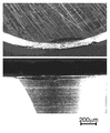
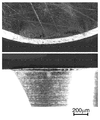
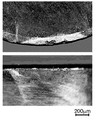
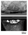
- Sample No. which is an example of the present invention The digital microscope photograph which showed the rake face and flank face of the cutting tool used for cutting of 1. The upper side of the drawing shows the rake face, and the lower side of the drawing shows the flank face. Sample No. which is an example of the present invention. 6 is a digital microscope photograph showing a rake face and a flank face of a cutting tool used for cutting No. 6; The upper side of the drawing shows the rake face, and the lower side of the drawing shows the flank face. Sample No. which is an example of the present invention. The digital microscope photograph which showed the rake face and flank face of the cutting tool used for 11 cutting. The upper side of the drawing shows the rake face, and the lower side of the drawing shows the flank face. Sample No.
- 22 is a digital microscope photograph showing a rake face and a flank face of a cutting tool used for 22 cutting operations.
- the upper side of the drawing shows the rake face, and the lower side of the drawing shows the flank face.
- Sample No. which is a comparative example. A digital microscope photograph showing the rake face and flank face of a cutting tool used for 30 cutting operations.
- the upper side of the drawing shows the rake face, and the lower side of the drawing shows the flank face.
- the upper side of the drawing shows the rake face, and the lower side of the drawing shows the flank face.
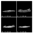
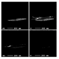
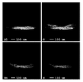
- FIG. 1A When the deposits formed on the surface of the cutting tool in FIG. 1A (sample No. 1) were analyzed by EPMA (electron beam microanalyzer), Al (upper left), O (upper right), Mn (lower left), S (right) FIG. It is a map figure of Al, O, Mn, and S when the deposit formed on the surface of the cutting tool of Drawing 1B (sample No. 6) is analyzed by EPMA (electron beam microanalyzer), respectively. It is a map figure of Al, O, Mn, and S when the deposit formed on the surface of the cutting tool of Drawing 1C (sample No. 11) is analyzed by EPMA (electron beam microanalyzer), respectively.
- EPMA electron beam microanalyzer
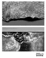
- Sample No. which is a comparative example It is the digital microscope photograph which showed the flank and rake face of the cutting tool used for the cutting process of D (cutting distance 10m). The upper side of the drawing shows the rake face, and the lower side of the drawing shows the flank face. Sample No. which is a comparative example. It is the digital microscope photograph which showed the flank and rake face of the cutting tool used for the cutting process of E (cutting distance 15m). The upper side of the drawing shows the rake face, and the lower side of the drawing shows the flank face.
- the feature of the present invention is that the machinability after tempering depends on the cutting temperature even when a large amount of undissolved carbide is formed to improve the temper hardness and control the crystal grain size.
- a good cold tool steel has been realized. Specifically, in addition to obtaining a tempered hardness of 60 HRC or higher, a composite of Al 2 O 3 that is a high melting point oxide and MnS that is a highly ductile inclusion in order to suppress wear of a cutting tool. This is because the steel material was designed so that a lubricating protective film was formed on the surface of the cutting tool.
- the present inventor examined machinability improving means that can widely correspond to the component composition of cold tool steel. As a result, we focused on the effectiveness of self-lubrication. And when self-lubricating action effect using a low melting point oxide like patent document 5 was examined, it discovered that this had the subject depending on cutting temperature.
- the low melting point oxide having self-lubricating properties is a composite oxide containing Fe and Cr that are generally contained in a large amount in a steel material. It fluctuates greatly and a stable lubricating effect cannot be obtained.
- the steel raw material which can achieve the refining hardness of 60HRC or more and can form this composite lubricating protective film has an optimal component range, and this has been specified, and thus the present invention has been achieved. .
- the composition of the cold tool steel of the present invention will be described.
- C 0.6 to 1.2% by mass (hereinafter simply expressed as%)
- C is an important element that forms carbides in the steel and imparts hardness to the cold tool steel. If the amount of C is too small, the amount of carbide formed is insufficient, and it is difficult to impart a hardness of 60 HRC or higher. On the other hand, if the content is excessive, the toughness tends to decrease due to an increase in the amount of undissolved carbide when quenched. Therefore, the C content is set to 0.6 to 1.2%. Preferably they are 0.7% or more and / or 1.0% or less.
- Si 0.7-2.5%
- Si is an important element that dissolves in steel and imparts hardness to cold tool steel.
- Fe and Cr it is an element that easily forms a corundum-based oxide with Al 2 O 3.
- Si is set to 0.7 to 2.5%. Preferably it is 0.8% or more and / or 2.0% or less.
- Mn is an important element of the present invention, and acts as a good lubricating film on the Al 2 O 3 protective film formed on the cutting tool surface. And it is an austenite formation element, and it dissolves in steel and improves hardenability. However, if the amount added is too large, a large amount of retained austenite remains after tempering, which may cause aging during tool use. Further, since the easily form a Fe and Cr and a low melting oxide, is a factor that inhibits the function of the Al 2 O 3 protective coating. Therefore, in the present invention, it was set to 0.3 to 2.0%. Preferably they are 0.4% or more and / or 1.5% or less.
- S is an important element of the present invention, and acts as a good lubricating film on the Al 2 O 3 protective film formed on the cutting tool surface. Addition of 0.02% or more is necessary in order to sufficiently exhibit such a lubricating action, but since S deteriorates the toughness of steel, the upper limit is made 0.1%. Preferably it is 0.03% or more and / or 0.08% or less.
- Cr 3.0 to less than 5.0% Cr imparts hardness to the cold tool steel by forming M 7 C 3 carbide in the tempered structure. In addition, a part of the material is present as insoluble carbide during quenching heating, and has an effect of suppressing the growth of crystal grains. However, if Cr is less than 3.0%, the amount of carbide formed is small, and it is difficult to achieve a hardness of 60 HRC or higher. On the other hand, by making Cr less than 5.0%, the amount of undissolved carbide is reduced and toughness is improved. And by suppressing the excessive formation of the low melting point oxide containing Cr, it is possible to improve the function of an Al 2 O 3 protective film made of Al, which will be described later, and to significantly improve the machinability.
- Mo and W are single or composite (Mo + 1 / 2W): 0.5 to 2.0% Mo and W are elements that improve the hardness by precipitation strengthening (secondary hardening) of fine carbides during tempering during tempering. However, at the same time, since the decomposition of residual austenite that occurs during tempering is delayed, when it is excessively contained, residual austenite tends to remain in the tempered structure. Further, since Mo and W are expensive elements, the amount of addition should be reduced as much as possible for practical use. Therefore, the addition amount of these elements is 0.5 to 2.0% in the relational expression of (Mo + 1 / 2W).
- Al 0.04 to less than 0.3%
- Al is an important element of the present invention, and forms high-melting-point oxide Al 2 O 3 on the cutting tool surface during cutting and functions as a protective film. . And by containing 0.04% or more, the protective film of sufficient thickness is formed and a tool life improves.
- the upper limit of the amount of Al added is less than 0.3%. Preferably they are 0.05% or more and / or 0.15% or less.
- the value of the machinability index MP obtained by the relational expression consisting of the amounts of S, Cr, and Al: 21.9 ⁇ S + 124.2 ⁇ (Al / Cr) ⁇ 2.1 is greater than 0.
- the adjustment of the machinability index MP is an indispensable requirement for sufficiently forming the composite lubricating protective film composed of Al 2 O 3 and MnS, which is the greatest feature of the present invention, on the tool surface at the time of cutting.
- a sufficient amount of Al contained in the steel material of the present invention forms Al 2 O 3 , which is a high melting point oxide, on the surface of the cutting tool by heat generated during the cutting process.
- Al 2 O 3 Since the melting point of Al 2 O 3 is about 2050 ° C., which is much higher than the cutting temperature, Al 2 O 3 functions as a protective film for the cutting tool. Furthermore, a sufficient amount of S contained in the steel material of the present invention forms MnS. In addition to being rich in ductility, MnS is well-familiar with Al 2 O 3 , so it is deposited on the above Al 2 O 3 protective film, and these serve as a good composite lubricating protective film.
- Ni 1.0% or less
- Ni is an element which improves the toughness and weldability of steel. Further, since tempering during tempering precipitates as Ni 3 Al and has an effect of increasing the hardness of the steel, it is effective to add it according to the amount of Al contained in the cold tool steel of the present invention.
- Ni is an expensive metal and is an element whose addition amount should be reduced as much as possible for practical use. In this case, the cold tool steel of the present invention can significantly reduce the amount of Cr, which is an expensive metal, as compared with JIS-SKD11, which is a typical cold tool steel. The amount added can be increased. Therefore, Ni of the present invention may be added up to 1.0% or less.
- Cu 1.0% or less Cu precipitates as (epsilon) -Cu in the tempering at the time of tempering, and has the effect of raising the hardness of steel.
- Cu is an element that causes hot brittleness of a steel material. Therefore, 1.0% or less of Cu in the present invention can be added.
- Ni In order to suppress hot brittleness due to Cu, it is also preferable to add Ni at the same time. And it is further more preferable that Cu and Ni at this time shall be substantially the same amount.
- V 1.0% or less
- V has the effect of forming various carbides and increasing the hardness of the steel.
- the formed insoluble MC carbide has an effect of suppressing the growth of crystal grains.
- Nb which will be described later
- the MC carbide that has not been dissolved yet during quenching heating becomes fine and uniform, and has the function of effectively suppressing crystal grain growth.
- MC carbide is hard and causes a decrease in machinability. Therefore, in the present invention, the above-described composite lubricating protective film is formed on the tool surface at the time of cutting, which is important in that good machinability can be ensured even if many MC carbides are formed in the steel material. Has characteristics.
- V is made 3.0% or more in order to suppress the formation of coarse MC carbides, but V is preferably made 1.0% or less even when added. More preferably, it is 0.7% or less.
- Nb 0.5% or less
- Nb has the function which forms MC carbide
- Cr is set to 3.0% or more in order to suppress the formation of coarse MC carbides.
- Nb is preferably set to 0.5% or less. More preferably, it is 0.3% or less.
- the cold tool steel of the present invention is used as pre-hardened steel, so that heat treatment deformation due to tempering is excluded, and finishing cutting can be omitted.
- a composite lubricating protective film is similarly formed on the surface of the cutting tool. Effective for improving tool life.
- the cold tool which consists of the cold tool steel of this invention, it is possible to further improve abrasion resistance, maintaining high dimensional accuracy by performing a surface PVD process.
- the material was melted using a high frequency induction melting furnace to produce an ingot having chemical components shown in Table 1. Next, hot forging was performed on these ingots so that the forging ratio was about 10, and after cooling, annealing was performed at 860 ° C. These annealing materials are subjected to quenching treatment by air cooling from 1030 ° C., and then tempered to a hardness of 60 ⁇ 2 HRC by two tempering treatments at 500 to 540 ° C. to evaluate machinability. A test piece was prepared. However, as shown in Table 1, sample No. 35 and 36 are Cr that forms M 7 C 3 carbide, Nb and V that form MC carbide are added in a small amount, so tempering at 500 to 540 ° C. does not provide a hardness of 55 HRC or more, and cold tools Not suitable for use as steel.
- the machinability test was carried out by plane cutting using an insert PICOmini manufactured by Hitachi Tool Co., Ltd. as a cutting edge replaceable tool corresponding to cutting of a hard material.
- the insert is made of cemented carbide as a base material and TiN coating is applied to the surface.
- Cutting conditions were a cutting speed of 70 m / min, a rotation speed of 1857 / min, a feed speed of 743 mm / min, a feed amount per blade of 0.4 mm / blade, a cutting depth of 0.15 mm, a cutting width of 6 mm, and a blade count of 1. .
- the machinability was evaluated based on the following two points. First, the formation amount of the composite lubricating protective film composed of Al 2 O 3 and MnS on the cutting tool surface was evaluated. This amount of formation was analyzed using EPMA from the rake face side at a cutting distance of 0.8 m immediately after the start of cutting, and was used as the average count number of Al and S at this time. Then, the cutting distance was extended to 8 m, and the amount of tool wear at this time was measured using an optical microscope. These evaluation results are shown in Table 2.
- the cold tool steel of the present invention a composite lubricating protective film is formed on the cutting tool surface, and tool wear is suppressed. And even when V and Nb which form insoluble carbides are added, good machinability is maintained. On the other hand, the cold tool steel that does not satisfy the machinability index MP of the present invention has a larger amount of tool wear than the present invention.
- Sample No. Nos. 33 and 34 have high machinability index MP but poor machinability. This is because a large amount of coarse MC carbide was formed as a result of adding a large amount of V and Nb in spite of a small amount of Cr added to ensure a hardness of 60 ⁇ 2 HRC.
- FIGS. 2A to 2E show the sample Nos. 2A to E are digital microscope photographs showing the flank and rake face of the cutting tool used in 1, 6, 11, 22, 30, and 34.
- FIGS. 2A to 2E show the deposits formed on the surface of FIGS. (The high concentration part of each element is shown in white).
- Sample Nos. With high average counts of Al and S were obtained.
- Sample No. with a negative machinability index MP was confirmed that Al and S were adhered over a wide range in the EPMA analysis of FIGS.
- Sample No. 22 The average count numbers of Al and S were lower than those of 1, 6 and 11, and the adhesion amount of Al and S was small.
- FIGS. 1A to 1E showing the wear state of the cutting tool
- the sample No It can be seen that deposits are remarkably adhered to the tool rake face of Nos. 1, 6, 11 and the tool wear is suppressed on both the flank face and the rake face. Moreover, tool wear is progressing uniformly and stably.
- sample no. The tool wear amount of No. 22 is the sample No. The tool was close to 1 and chipping occurred in the tool. And sample no. 30 and sample no. The tool surface of No. 34 is also sample No. Like 22 the damage was severe.
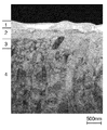
- FIGS. It is the cross-sectional TEM (transmission electron microscope) image which showed the deposit
- reference numeral 1 is a protective film for sample preparation
- 2 is a deposit on cutting
- 3 is a TiN plastic deformation region
- 4 is a TiN undeformed region.
- the sample Nos. No. 1 deposit is thicker, and the sample number increases as the count number decreases. In 22, the deposit was thinly transferred. Sample No. At 30, almost no deposits were observed. And sample no. Similar to sample 1, sample no. Al 2 O 3 and MnS were also attached to the surface of the tool No. 22, but the thickness was thin and chipping occurred as described above.
- Sample No. No. 1 has a high lubrication protection function because the TiN coating on the tool surface, which is usually plastically deformed by frictional stress during cutting, has a thick deposit. 1 is suppressed (the plastic deformation region is the narrowest).
- the work material was produced from an ingot having chemical components shown in Table 3 using a high frequency induction melting furnace and an atmospheric arc melting furnace. Hot forging was performed so that the forging ratio was about 5 with respect to the ingot, and after cooling, annealing was performed at 860 ° C. These annealed materials were quenched by air cooling from 1030 ° C. and then tempered to a hardness of 60 ⁇ 2 HRC by tempering twice at 500 to 540 ° C. to prepare test pieces.
- Fig. 4 shows the transition of the carbide substrate exposed width on the flank of the cutting tool when the cutting distance is extended to 25m
- Figs. 5A to E show digital microscope photographs showing the flank and rake face of the cutting tool. Show. Even if the cold tool steel according to the present invention is cut to 25 m, the exposed width of the base material is 0.02 mm or less, and the tool is hardly damaged. On the other hand, the cold tool steel that does not satisfy the present invention is already exposed to 0.05 mm or more at the stage of the cutting distance of 10 m. In 3 and 4, chipping occurred. Thus, it was confirmed that the cold tool steel of the present invention was excellent in machinability even under cutting conditions different from those in Example 1.
Landscapes
- Chemical & Material Sciences (AREA)
- Engineering & Computer Science (AREA)
- Materials Engineering (AREA)
- Mechanical Engineering (AREA)
- Metallurgy (AREA)
- Organic Chemistry (AREA)
- Physics & Mathematics (AREA)
- Thermal Sciences (AREA)
- Crystallography & Structural Chemistry (AREA)
- Heat Treatment Of Steel (AREA)
- Heat Treatment Of Articles (AREA)
- Cutting Tools, Boring Holders, And Turrets (AREA)
Abstract
Description
C:0.6~1.2%、
Si:0.7~2.5%、
Mn:0.3~2.0%、
S:0.02~0.1%、
Cr:3.0~5.0%未満、
MoおよびWは単独または複合で(Mo+1/2W):0.5~2.0%、
Al:0.04~0.3%未満、
残部Feおよび不可避的不純物からなり、
上記のS、Cr、Al量からなる関係式:21.9×S+124.2×(Al/Cr)-2.1によって求められる被削性指数MPの値が0超であることを特徴とする調質後の被削性に優れた冷間工具鋼である。好ましくは、調質後の硬さが60HRC以上である。
Cは、鋼中で炭化物を形成し、冷間工具鋼に硬さを付与する重要な元素である。Cが少なすぎると形成される炭化物量が不足し、60HRC以上の硬さを付与することが困難である。一方、過多の含有は、焼入れしたときの未固溶炭化物量の増加により靱性が低下しやすい。よって、Cの含有量は0.6~1.2%とした。好ましくは0.7%以上および/または1.0%以下である。
Siは、鋼中に固溶して、冷間工具鋼に硬さを付与する重要な元素である。また、FeやCrよりも酸化傾向が強いことに加えて、Al2O3とコランダム系の酸化物を形成しやすい元素であるため、本発明では酸化物を低融点化するFe系酸化物やCr系酸化物の形成を抑制し、Al2O3保護皮膜の形成を促進する重要な作用がある。しかし、多すぎると焼入れ性や靱性が著しく低下する。よって、Siは0.7~2.5%とした。好ましくは0.8%以上および/または2.0%以下である。
Mnは、本発明の重要な元素であり、切削工具表面に形成されたAl2O3保護皮膜上で良好な潤滑皮膜として作用する。そして、オーステナイト形成元素であり、鋼中に固溶して焼入れ性を向上する。しかし、添加量が多すぎると調質後に残留オーステナイトが多く残り、工具使用時の経年変寸の原因となる。また、FeやCrと低融点酸化物を形成しやすいため、Al2O3保護皮膜の機能を阻害する要因となる。よって、本発明では0.3~2.0%とした。好ましくは0.4%以上および/または1.5%以下である。
Sは、本発明の重要な元素であり、切削工具表面に形成されたAl2O3保護皮膜上で良好な潤滑皮膜として作用する。このような潤滑作用が十分に発揮されるためには0.02%以上の添加が必要であるが、Sは鋼の靱性を劣化させるため、上限は0.1%とする。好ましくは0.03%以上および/または0.08%以下である。
Crは、調質後の組織中にM7C3炭化物を形成することで、冷間工具鋼に硬さを付与する。また、焼入加熱時に一部は未固溶炭化物として存在して、結晶粒の成長を抑制する効果がある。ただし、Crが3.0%未満では、形成される炭化物量が少なく、60HRC以上の硬さを達成することが困難である。一方、Crを5.0%未満とすることで、未固溶炭化物量が減少して、靱性が向上する。そして、Crを含む低融点酸化物の過多の形成を抑えることで、後述のAlによるAl2O3保護皮膜の機能を向上することができ、被削性を著しく向上させることが可能となる。また、結晶粒の成長抑制や硬さ付与の目的で、硬質のMC炭化物を形成するVやNbを添加する場合、M7C3炭化物と共存させることで、粗大なMC炭化物の形成を抑制する効果もあるが、Crが3.0%未満の場合はその効果が十分に得られず、被削性が低下する。このため、Crは3.0~5.0%未満とすることが重要である。好ましくは3.1%以上および/または4.8%以下である。
MoおよびWは、調質時の焼戻しにおいて、微細炭化物の析出強化(二次硬化)により硬さを向上させる元素である。しかし同時には、焼戻しで起こる残留オーステナイトの分解を遅滞させるため、過多に含有すると、調質後の組織に残留オーステナイトが残りやすい。また、MoやWは高価な元素であるため、実用化する上では添加量を極力低減すべきである。よって、これら元素の添加量は(Mo+1/2W)の関係式で0.5~2.0%とする。
Alは、本発明の重要な元素であり、切削加工時に高融点酸化物であるAl2O3を切削工具表面に形成し、保護皮膜として機能する。そして、0.04%以上を含有することで、十分な厚さの保護皮膜が形成され、工具寿命が改善する。しかし、Alを多量に添加した場合は、鋼素材中にAl2O3が介在物として多く形成されるため、鋼素材の被削性がかえって低下する。このため、Al添加量の上限は0.3%未満とする。好ましくは0.05%以上および/または0.15%以下である。
被削性指数MPの調整は、本発明の最大の特徴であるAl2O3とMnSからなる複合潤滑保護皮膜を、切削加工時の工具表面に十分に形成させるための必須要件である。本発明の鋼素材中に含まれる十分量のAlは、切削加工時に発生する熱によって高融点酸化物であるAl2O3を切削工具の表面に形成する。Al2O3の融点は約2050℃であり、これは切削温度よりも遥かに高いため、Al2O3は切削工具の保護皮膜として機能する。さらに、本発明の鋼素材中に含まれる十分量のSは、MnSを形成する。MnSは延性に富むことに加え、Al2O3との馴染みが良いため、上記のAl2O3保護皮膜上に堆積して、これらが良好な複合潤滑保護皮膜としての役割を果たす。
Niは、鋼の靱性や溶接性を改善する元素である。また、調質時の焼戻しではNi3Alとして析出し、鋼の硬さを高める効果があるので、本発明の冷間工具鋼が含有するAl量に応じて添加することは有効である。一方、Niは高価な金属であり、実用化する上では添加量を極力低減すべき元素である。この場合、本発明の冷間工具鋼は、同様に高価な金属であるCrの添加量を代表的な冷間工具鋼であるJIS-SKD11よりも大幅に低減できているので、その分Niの添加量を上げることができる。そこで、本発明のNiは、1.0%以下までなら添加してもよい。
Cuは、調質時の焼戻しにおいてε-Cuとして析出し、鋼の硬さを高める効果がある。ただし、Cuは鋼素材の熱間脆性を引き起こす元素である。よって、本発明におけるCuは、1.0%以下を添加することができる。なお、Cuによる熱間脆性を抑制するには、Niを同時に添加することも好ましい。そして、このときのCuとNiは、ほぼ同量とすることが、さらに好ましい。
Vは、種々の炭化物を形成して、鋼の硬さを高める効果がある。また、形成された未固溶のMC炭化物は、結晶粒の成長を抑制する効果がある。そして特に、後述のNbと複合添加することで、焼入加熱時に未固溶のMC炭化物が微細かつ均一となり、結晶粒成長を効果的に抑制する働きがある。一方、MC炭化物は硬質であり、被削性を低下させる原因となる。そこで本発明では、上述した複合潤滑保護皮膜を切削加工時の工具表面に形成させたことで、鋼素材中に多くのMC炭化物を形成しても良好な被削性を確保できる点に重要な特徴を有する。ただし、過多のV添加は、粗大なMC炭化物を過剰に形成して、冷間工具鋼の靱性や被削性を低下させる。本発明では、粗大なMC炭化物の形成を抑制するためCrを3.0%以上としているが、Vは添加する場合でも1.0%以下とすることが好ましい。より好ましくは0.7%以下である。
Nbは、MC炭化物を形成して、結晶粒の粗大化を抑える働きがある。ただし、過多に添加すると、粗大なMC炭化物が過剰に形成されて、鋼の靱性や被削性が低下する。本発明では、粗大なMC炭化物の形成を抑制するためCrを3.0%以上としているが、この場合においてもNbは0.5%以下とすることが好ましい。より好ましくは0.3%以下である。


Claims (6)
- 質量%で、
C:0.6~1.2%、
Si:0.7~2.5%、
Mn:0.3~2.0%、
S:0.02~0.1%、
Cr:3.0~5.0%未満、
MoおよびWは単独または複合で(Mo+1/2W):0.5~2.0%、
Al:0.04~0.3%未満、
残部Feおよび不可避的不純物からなり、
上記のS、Cr、Al量からなる関係式:21.9×S+124.2×(Al/Cr)-2.1によって求められる被削性指数MPの値が0超であることを特徴とする被削性に優れた冷間工具鋼。 - 質量%で、Ni:1.0%以下をさらに含有することを特徴とする請求項1に記載の被削性に優れた冷間工具鋼。
- 質量%で、Cu:1.0%以下をさらに含有することを特徴とする請求項1または2に記載の被削性に優れた冷間工具鋼。
- 質量%で、V:1.0%以下をさらに含有することを特徴とする請求項1ないし3のいずれかに記載の被削性に優れた冷間工具鋼。
- 質量%で、Nb:0.5%以下をさらに含有することを特徴とする請求項1ないし4のいずれかに記載の被削性に優れた冷間工具鋼。
- 調質後の硬さが60HRC以上であることを特徴とする請求項1ないし5のいずれかに記載の被削性に優れた冷間工具鋼。
Priority Applications (3)
| Application Number | Priority Date | Filing Date | Title |
|---|---|---|---|
| CN201280009816.XA CN103403206B (zh) | 2011-02-21 | 2012-02-20 | 切削性优异的冷作工具钢 |
| EP12749932.5A EP2679698B1 (en) | 2011-02-21 | 2012-02-20 | Cold-work tool steel exhibiting superior machinability |
| JP2013501015A JP5672466B2 (ja) | 2011-02-21 | 2012-02-20 | 被削性に優れた冷間工具鋼 |
Applications Claiming Priority (2)
| Application Number | Priority Date | Filing Date | Title |
|---|---|---|---|
| JP2011034187 | 2011-02-21 | ||
| JP2011-034187 | 2011-02-21 |
Publications (1)
| Publication Number | Publication Date |
|---|---|
| WO2012115024A1 true WO2012115024A1 (ja) | 2012-08-30 |
Family
ID=46720801
Family Applications (1)
| Application Number | Title | Priority Date | Filing Date |
|---|---|---|---|
| PCT/JP2012/053928 Ceased WO2012115024A1 (ja) | 2011-02-21 | 2012-02-20 | 被削性に優れた冷間工具鋼 |
Country Status (5)
| Country | Link |
|---|---|
| EP (1) | EP2679698B1 (ja) |
| JP (1) | JP5672466B2 (ja) |
| CN (1) | CN103403206B (ja) |
| TW (1) | TWI447233B (ja) |
| WO (1) | WO2012115024A1 (ja) |
Cited By (2)
| Publication number | Priority date | Publication date | Assignee | Title |
|---|---|---|---|---|
| WO2014156487A1 (ja) | 2013-03-29 | 2014-10-02 | 日立金属株式会社 | 金型用鋼素材およびその製造方法、金型用プリハードン鋼材の製造方法、冷間加工用金型の製造方法 |
| WO2014192730A1 (ja) | 2013-05-30 | 2014-12-04 | 日立金属株式会社 | 冷間加工用金型の製造方法 |
Families Citing this family (3)
| Publication number | Priority date | Publication date | Assignee | Title |
|---|---|---|---|---|
| CN106917045B (zh) * | 2017-03-07 | 2019-03-05 | 广西大学行健文理学院 | 铸造冷镦模具的制造方法 |
| CN110016617B (zh) * | 2019-05-08 | 2021-05-04 | 上海大学 | 一种冷作模具钢及其制备方法 |
| JP7478685B2 (ja) * | 2020-02-19 | 2024-05-07 | クエステック イノベーションズ リミテッド ライアビリティ カンパニー | 析出強化された浸炭可能及び窒化可能な合金鋼 |
Citations (7)
| Publication number | Priority date | Publication date | Assignee | Title |
|---|---|---|---|---|
| JP2001316769A (ja) | 2000-05-10 | 2001-11-16 | Daido Steel Co Ltd | 冷間工具鋼 |
| JP2005272899A (ja) | 2004-03-23 | 2005-10-06 | Nippon Koshuha Steel Co Ltd | 自己潤滑性を有する工具鋼 |
| JP2006169624A (ja) * | 2004-11-18 | 2006-06-29 | Hitachi Metals Ltd | 変寸抑制特性および耐カジリ性に優れた冷間ダイス鋼 |
| JP2006193790A (ja) | 2005-01-14 | 2006-07-27 | Daido Steel Co Ltd | 冷間工具鋼 |
| JP2007002333A (ja) * | 2005-05-26 | 2007-01-11 | Hitachi Metals Ltd | 優れた自己潤滑特性を有するプレス金型 |
| JP2008189982A (ja) | 2007-02-02 | 2008-08-21 | Daido Steel Co Ltd | 工具鋼 |
| JP2009132990A (ja) | 2007-10-31 | 2009-06-18 | Daido Steel Co Ltd | 合金工具鋼及びその製造方法 |
Family Cites Families (7)
| Publication number | Priority date | Publication date | Assignee | Title |
|---|---|---|---|---|
| US8900382B2 (en) * | 2002-06-13 | 2014-12-02 | Uddeholm Tooling Aktiebolag | Hot worked steel and tool made therewith |
| US7722727B2 (en) * | 2002-06-13 | 2010-05-25 | Uddeholm Tooling Aktiebolag | Steel and mould tool for plastic materials made of the steel |
| JP2004169177A (ja) * | 2002-11-06 | 2004-06-17 | Daido Steel Co Ltd | 合金工具鋼及びその製造方法、並びにそれを用いた金型 |
| CN100381599C (zh) * | 2005-06-22 | 2008-04-16 | 贵州大学 | 低成本的高速钢 |
| CN101528962A (zh) * | 2006-10-17 | 2009-09-09 | 株式会社神户制钢所 | 冷加工模具钢、模具和用于制造冷加工模具钢的方法 |
| JP5143531B2 (ja) * | 2007-11-13 | 2013-02-13 | 株式会社神戸製鋼所 | 冷間金型用鋼および金型 |
| JP2009174017A (ja) * | 2008-01-25 | 2009-08-06 | Hitachi Metals Ltd | 表面被覆処理用合金及び摺動部材 |
-
2012
- 2012-02-20 JP JP2013501015A patent/JP5672466B2/ja active Active
- 2012-02-20 CN CN201280009816.XA patent/CN103403206B/zh active Active
- 2012-02-20 WO PCT/JP2012/053928 patent/WO2012115024A1/ja not_active Ceased
- 2012-02-20 TW TW101105392A patent/TWI447233B/zh active
- 2012-02-20 EP EP12749932.5A patent/EP2679698B1/en active Active
Patent Citations (7)
| Publication number | Priority date | Publication date | Assignee | Title |
|---|---|---|---|---|
| JP2001316769A (ja) | 2000-05-10 | 2001-11-16 | Daido Steel Co Ltd | 冷間工具鋼 |
| JP2005272899A (ja) | 2004-03-23 | 2005-10-06 | Nippon Koshuha Steel Co Ltd | 自己潤滑性を有する工具鋼 |
| JP2006169624A (ja) * | 2004-11-18 | 2006-06-29 | Hitachi Metals Ltd | 変寸抑制特性および耐カジリ性に優れた冷間ダイス鋼 |
| JP2006193790A (ja) | 2005-01-14 | 2006-07-27 | Daido Steel Co Ltd | 冷間工具鋼 |
| JP2007002333A (ja) * | 2005-05-26 | 2007-01-11 | Hitachi Metals Ltd | 優れた自己潤滑特性を有するプレス金型 |
| JP2008189982A (ja) | 2007-02-02 | 2008-08-21 | Daido Steel Co Ltd | 工具鋼 |
| JP2009132990A (ja) | 2007-10-31 | 2009-06-18 | Daido Steel Co Ltd | 合金工具鋼及びその製造方法 |
Cited By (4)
| Publication number | Priority date | Publication date | Assignee | Title |
|---|---|---|---|---|
| WO2014156487A1 (ja) | 2013-03-29 | 2014-10-02 | 日立金属株式会社 | 金型用鋼素材およびその製造方法、金型用プリハードン鋼材の製造方法、冷間加工用金型の製造方法 |
| WO2014192730A1 (ja) | 2013-05-30 | 2014-12-04 | 日立金属株式会社 | 冷間加工用金型の製造方法 |
| EP3006601A4 (en) * | 2013-05-30 | 2016-11-02 | Hitachi Metals Ltd | PROCESS FOR PREPARING A FORM FOR USE FOR COLD PROCESSING |
| JPWO2014192730A1 (ja) * | 2013-05-30 | 2017-02-23 | 日立金属株式会社 | 冷間加工用金型の製造方法 |
Also Published As
| Publication number | Publication date |
|---|---|
| EP2679698B1 (en) | 2018-09-12 |
| CN103403206B (zh) | 2015-11-25 |
| JPWO2012115024A1 (ja) | 2014-07-07 |
| JP5672466B2 (ja) | 2015-02-18 |
| CN103403206A (zh) | 2013-11-20 |
| EP2679698A1 (en) | 2014-01-01 |
| TWI447233B (zh) | 2014-08-01 |
| EP2679698A4 (en) | 2017-01-04 |
| TW201241191A (en) | 2012-10-16 |
Similar Documents
| Publication | Publication Date | Title |
|---|---|---|
| JP5843173B2 (ja) | 冷間加工用金型の製造方法 | |
| TWI412606B (zh) | 高周波淬火用鋼 | |
| CN101668874B (zh) | 冷作模具用钢及模具 | |
| JP5672466B2 (ja) | 被削性に優れた冷間工具鋼 | |
| JP4860774B1 (ja) | 冷間工具鋼 | |
| JP2014031575A (ja) | 高硬度冷間金型用鋼およびその製造方法 | |
| CN100451158C (zh) | 模具钢 | |
| JP2010163648A (ja) | 冷間金型用鋼および金型 | |
| JP5316425B2 (ja) | 表面被覆処理用合金及び摺動部材 | |
| JP4411594B2 (ja) | 冷間加工用金型 | |
| JP4269293B2 (ja) | 金型用鋼 | |
| JP2019019397A (ja) | 被削性に優れたプリハードン熱間工具鋼 | |
| JP6416624B2 (ja) | 冷間工具鋼の切削方法及び冷間金型材料の製造方法 | |
| JP2004277818A (ja) | プラスチック成形用の快削性金型用鋼 | |
| WO2012043228A1 (ja) | 表面pvd処理用高硬度プリハードン冷間工具鋼およびその製造方法、ならびにその表面pvd処理方法 | |
| JP3191008B2 (ja) | 熱間工具鋼 | |
| JP2018154884A (ja) | 冷間工具鋼 | |
| JP2021095606A (ja) | 軟化抵抗性及び窒化特性に優れた高強度熱間工具鋼 | |
| JP7608772B2 (ja) | 金型用鋼及び金型 | |
| WO2021149601A1 (ja) | マルテンサイト系ステンレス鋼板およびマルテンサイト系ステンレス鋼部材 | |
| JP2008038219A (ja) | 被削性および靭性に優れたプリハードン鋼 |
Legal Events
| Date | Code | Title | Description |
|---|---|---|---|
| 121 | Ep: the epo has been informed by wipo that ep was designated in this application |
Ref document number: 12749932 Country of ref document: EP Kind code of ref document: A1 |
|
| ENP | Entry into the national phase |
Ref document number: 2013501015 Country of ref document: JP Kind code of ref document: A |
|
| WWE | Wipo information: entry into national phase |
Ref document number: 2012749932 Country of ref document: EP |
|
| NENP | Non-entry into the national phase |
Ref country code: DE |
|
| WWE | Wipo information: entry into national phase |
Ref document number: 1301004600 Country of ref document: TH |