WO2012115100A1 - 混合物の分離方法及び装置 - Google Patents
混合物の分離方法及び装置 Download PDFInfo
- Publication number
- WO2012115100A1 WO2012115100A1 PCT/JP2012/054116 JP2012054116W WO2012115100A1 WO 2012115100 A1 WO2012115100 A1 WO 2012115100A1 JP 2012054116 W JP2012054116 W JP 2012054116W WO 2012115100 A1 WO2012115100 A1 WO 2012115100A1
- Authority
- WO
- WIPO (PCT)
- Prior art keywords
- particles
- magnetic field
- mixture
- liquid
- separation tank
- Prior art date
- Legal status (The legal status is an assumption and is not a legal conclusion. Google has not performed a legal analysis and makes no representation as to the accuracy of the status listed.)
- Ceased
Links
Images


Classifications
-
- B—PERFORMING OPERATIONS; TRANSPORTING
- B03—SEPARATION OF SOLID MATERIALS USING LIQUIDS OR USING PNEUMATIC TABLES OR JIGS; MAGNETIC OR ELECTROSTATIC SEPARATION OF SOLID MATERIALS FROM SOLID MATERIALS OR FLUIDS; SEPARATION BY HIGH-VOLTAGE ELECTRIC FIELDS
- B03C—MAGNETIC OR ELECTROSTATIC SEPARATION OF SOLID MATERIALS FROM SOLID MATERIALS OR FLUIDS; SEPARATION BY HIGH-VOLTAGE ELECTRIC FIELDS
- B03C1/00—Magnetic separation
- B03C1/02—Magnetic separation acting directly on the substance being separated
- B03C1/025—High gradient magnetic separators
- B03C1/031—Component parts; Auxiliary operations
- B03C1/033—Component parts; Auxiliary operations characterised by the magnetic circuit
- B03C1/0335—Component parts; Auxiliary operations characterised by the magnetic circuit using coils
-
- B—PERFORMING OPERATIONS; TRANSPORTING
- B03—SEPARATION OF SOLID MATERIALS USING LIQUIDS OR USING PNEUMATIC TABLES OR JIGS; MAGNETIC OR ELECTROSTATIC SEPARATION OF SOLID MATERIALS FROM SOLID MATERIALS OR FLUIDS; SEPARATION BY HIGH-VOLTAGE ELECTRIC FIELDS
- B03B—SEPARATING SOLID MATERIALS USING LIQUIDS OR USING PNEUMATIC TABLES OR JIGS
- B03B5/00—Washing granular, powdered or lumpy materials; Wet separating
- B03B5/28—Washing granular, powdered or lumpy materials; Wet separating by sink-float separation
- B03B5/30—Washing granular, powdered or lumpy materials; Wet separating by sink-float separation using heavy liquids or suspensions
- B03B5/44—Application of particular media therefor
-
- B—PERFORMING OPERATIONS; TRANSPORTING
- B03—SEPARATION OF SOLID MATERIALS USING LIQUIDS OR USING PNEUMATIC TABLES OR JIGS; MAGNETIC OR ELECTROSTATIC SEPARATION OF SOLID MATERIALS FROM SOLID MATERIALS OR FLUIDS; SEPARATION BY HIGH-VOLTAGE ELECTRIC FIELDS
- B03C—MAGNETIC OR ELECTROSTATIC SEPARATION OF SOLID MATERIALS FROM SOLID MATERIALS OR FLUIDS; SEPARATION BY HIGH-VOLTAGE ELECTRIC FIELDS
- B03C1/00—Magnetic separation
- B03C1/02—Magnetic separation acting directly on the substance being separated
- B03C1/28—Magnetic plugs and dipsticks
- B03C1/288—Magnetic plugs and dipsticks disposed at the outer circumference of a recipient
-
- B—PERFORMING OPERATIONS; TRANSPORTING
- B03—SEPARATION OF SOLID MATERIALS USING LIQUIDS OR USING PNEUMATIC TABLES OR JIGS; MAGNETIC OR ELECTROSTATIC SEPARATION OF SOLID MATERIALS FROM SOLID MATERIALS OR FLUIDS; SEPARATION BY HIGH-VOLTAGE ELECTRIC FIELDS
- B03C—MAGNETIC OR ELECTROSTATIC SEPARATION OF SOLID MATERIALS FROM SOLID MATERIALS OR FLUIDS; SEPARATION BY HIGH-VOLTAGE ELECTRIC FIELDS
- B03C1/00—Magnetic separation
- B03C1/32—Magnetic separation acting on the medium containing the substance being separated, e.g. magneto-gravimetric-, magnetohydrostatic-, or magnetohydrodynamic separation
-
- B—PERFORMING OPERATIONS; TRANSPORTING
- B03—SEPARATION OF SOLID MATERIALS USING LIQUIDS OR USING PNEUMATIC TABLES OR JIGS; MAGNETIC OR ELECTROSTATIC SEPARATION OF SOLID MATERIALS FROM SOLID MATERIALS OR FLUIDS; SEPARATION BY HIGH-VOLTAGE ELECTRIC FIELDS
- B03C—MAGNETIC OR ELECTROSTATIC SEPARATION OF SOLID MATERIALS FROM SOLID MATERIALS OR FLUIDS; SEPARATION BY HIGH-VOLTAGE ELECTRIC FIELDS
- B03C2201/00—Details of magnetic or electrostatic separation
- B03C2201/18—Magnetic separation whereby the particles are suspended in a liquid
Definitions
- the present invention relates to a mixture separation method and a separation apparatus for separating a mixture containing a plurality of types of substances for each type of substance using a magnetic field having a magnetic field gradient, or for separating a specific type of substance from the mixture.
- Patent Document 1 Japanese Patent Laid-Open No. 2002-59026 discloses a method for separating a mixture using the magnetic Archimedes effect.
- a mixture of a plurality of types of diamagnetic plastic particles is put into a support liquid, and a magnetic field having a magnetic field gradient, that is, a gradient magnetic field is applied, whereby the diamagnetic plastic particles of the mixture have their physical properties ( It floats at a position corresponding to the volume magnetic susceptibility and density), and plastic particles are sorted by type.
- a mixture containing a plurality of kinds of substances such as a mixture obtained from the waste disclosed in Patent Document 1, is added to the magnetic Archimedes effect (or particles in a medium as in the invention described in Patent Document 2). If separation is performed for each type using magnetic force or magnetic buoyancy, the separation device and the separation process will be significantly simplified and more efficient.
- FIG. 4 of Patent Document 2 shows a method of collecting particles floating by a supporting liquid and floating in a magnetic field using a collection net, but the turbulent flow of the supporting liquid (turbulent flow and streamline The meandering position of the particles may change due to meandering, and the separation accuracy of the particles may deteriorate.
- FIG. 4 of Patent Document 2 when a plurality of collection nets are arranged in series along the flow path, the downstream collection is caused by the influence of disturbance due to the upstream collection net. There is also a possibility that the separation accuracy of the particles in the net is deteriorated.
- metal particles having a high density are included in the mixture, the metal particles that have settled down to the bottom of the channel need to be swept away, so that the above-described problems are likely to occur.
- the present invention solves the above-mentioned problem, and uses a gradient magnetic field to continuously and highly accurately separate a mixture containing a plurality of types of particles of different materials for each type of material. I will provide a. Furthermore, the present invention provides a method and apparatus capable of continuously and accurately separating particles of a specific substance from a mixture including a plurality of types of particles having different substances using a gradient magnetic field.
- a mixture containing at least two kinds of particles in which one kind of particles is a paramagnetic substance or a diamagnetic substance is separated for each kind, or the one kind of particles is separated from the mixture.
- a method for separating a mixture wherein a magnetic field gradient having a vertical component and a horizontal component is applied to a support liquid stored in a separation tank, and the support liquid to which the magnetic field is applied is applied to the support liquid.
- the apparatus for separating a mixture of the present invention separates a mixture containing at least two kinds of particles, wherein one kind of particles is a paramagnetic substance or a diamagnetic substance, or separates the one kind of particles from the mixture.
- a separation tank for storing a supporting liquid, a magnetic field generating means for applying a magnetic field having a magnetic field gradient having a vertical component and a horizontal component to the supporting liquid, and one end side of the separation tank
- the recovery means recovers the one type of particles arranged at the predetermined height or the liquid level of the support liquid from the separation tank, and the other of the at least two types of particles is recovered.
- the type of particles are arranged at a position different from the one type of particles in the vertical direction between the bottom surface of the separation tank and the liquid level of the support liquid.
- the separation tank is provided with a substantially horizontal shelf, and the one kind of particles may be lowered in the support liquid and placed on the shelf.
- the one kind of particles may be stably magnetically levitated at the predetermined height in the supporting liquid.
- the magnetic field may be generated using a superconducting bulk magnet or magnetic field generating means having a solenoid coil whose coil central axis is tilted with respect to the vertical direction.
- the magnetic field is a combination of the first magnetic field generated by the first magnetic field generating unit and the second magnetic field generated by the second magnetic field generating unit, and the magnetic field of the first magnetic field.
- the gradient may be in the vertical direction, and the magnetic field gradient of the second magnetic field may be in the horizontal direction.
- the support liquid may be an aqueous solution containing at least one paramagnetic inorganic salt. More specifically, the supporting liquid is at least one normal selected from the group consisting of manganese chloride, cobalt chloride, nickel chloride, ferrous chloride, cobalt nitrate, nickel nitrate, gadolinium nitrate, dysprosium nitrate and terbium nitrate. It may be an aqueous solution containing a magnetic inorganic salt.
- the magnetic field gradient of the magnetic field applied to the particles and the support liquid contained in the mixture has a horizontal component in addition to the vertical component.
- paramagnetic or diamagnetic particles contained in the mixture are subjected to a horizontal force due to the magnetic field, and the particles are separated while moving in the horizontal direction from the input or introduction place to the collection place. It is guided from the bottom of the tank to a predetermined height, or moves horizontally from the charging place to the collecting place in a state of being magnetically levitated on the surface of the supporting liquid.
- the magnetic or diamagnetic particles contained in the mixture and the other particles are between the bottom surface of the separation tank and the liquid surface of the support liquid. Are arranged at different heights in the vertical direction.
- the particles of the mixture move by magnetic force from the place where the support liquid is charged to the collection place, so that the separated particles can be collected while introducing the mixture into the support liquid.
- the mixture since it is not necessary to flush the supporting liquid for the movement of the particles, the mixture can be separated with high accuracy by type, or specific types of particles can be separated from the mixture with high accuracy.
- FIG. 9A and FIG. 9B is an explanatory diagram showing an outline of an example according to the third embodiment of the present invention. It is a photograph which shows the pattern which the aluminum particle and the titanium particle floated in the support liquid in the Example which concerns on 3rd Embodiment of this invention.
- FIGS. 12A to 12C are an example according to the third embodiment of the present invention, in which glass particles and alumina particles are suspended in the supporting liquid and further moved in the horizontal direction. It is a photograph showing a pattern.
- FIGS. 13A to 13C is an example according to the third embodiment of the present invention after the glass particles and the alumina particles float in the supporting liquid and further move in the horizontal direction. It is a photograph showing a pattern.
- FIGS. 12A to 12C is an example according to the third embodiment of the present invention after the glass particles and the alumina particles float in the supporting liquid and further move in the horizontal direction. It is a photograph showing a pattern.
- 14A to 14C is an example according to the third embodiment of the present invention after the glass particles and the alumina particles float in the supporting liquid and further move in the horizontal direction. It is a photograph showing a pattern. It is a graph which shows the distribution of the magnetic field by the superconducting bulk magnet used in the experiment example regarding this invention, and a magnetic field x magnetic field gradient. It is a table
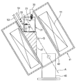
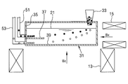
- FIG. 1 is a cross-sectional view showing an outline of a mixture separation device according to a first embodiment of the separation method or separation device of the present invention
- FIG. 2 is an enlarged view of a part of the mixture separation device.
- the mixture separation device according to the first embodiment is a magnetic field generation means of the present invention, and includes a magnet (11) that generates a gradient magnetic field and a separation tank (31) in which a supporting liquid (21) is stored.
- the magnet (11) is a superconducting electromagnet using a solenoid coil, and the wire made of a superconducting material (Nb 3 Sn, NbTi, etc.) constituting the magnet (11) is, for example, a cylindrical shape made of stainless steel. Or it is wound inside the doughnut-shaped container (41) so as to surround the inner wall (43) of the container (41).
- a cooling mechanism (not shown) for cooling the magnet (11) is provided inside the container (41).
- a normal electromagnet may be used as the magnet (11).
- the mixture separation device of the first embodiment is provided with legs (45) for supporting the container (41).
- the container (41) is fixed to the leg (45) in a state where the coil central axis A of the magnet (11) is inclined with respect to the vertical direction.
- 1 and 2 show a state in which the coil central axis A of the magnet (11) is inclined by approximately 30 degrees with respect to the vertical direction.
- the inclination angle of the magnet (11) (and the shape of the support portion (47) described later) may be appropriately adjusted according to the mixture to be processed and the support liquid (21) to be used.
- a rectangular or box-shaped separation tank (31) is disposed in the inner space surrounded by the inner wall (43) of the container (41).
- the separation tank (31) is supported by a support portion (47) fixed to the inner wall (43) of the container (41).
- the separation tank (31) and the support part (47) are made of a nonmagnetic material such as plastic or nonmagnetic stainless steel.
- a hopper (33) At one end of the upper part of the separation tank (31), there is provided a hopper (33) as a mixture introduction or introduction means, and the mixture to be treated is introduced into the supporting liquid (21) in the separation tank (31). Used to do.
- a shelf (37) projects horizontally from the wall (35) on the opposite side of the hopper (33).
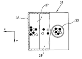
- FIG. 3 is a top view of the separation tank (31) partially broken.
- the mixture processed using the method or apparatus for separating a mixture of the present invention contains a plurality of types of particles having different substances, and at least one type of the plurality of types of particles is a paramagnetic substance or an antireactive material. It is made of a magnetic material.
- the mixture to be processed by the mixture separation apparatus of the first embodiment was formed of a first particle (indicated by ⁇ ) formed of a paramagnetic material or a diamagnetic material, and a material different from the material forming the first particle.
- the second type of particles may be formed of any of a paramagnetic material, a diamagnetic material, and a ferromagnetic material.
- the separation tank (31) is connected to a collecting means for individually collecting the separated first particles and second particles.
- a suction tube (51) for collecting the first particles and a suction tube (53) for collecting the second particles are provided (in FIGS. 2 and 3, the suction tube ( 51) (53) is omitted).
- Each of the suction pipes (51) and (53) is connected to the separation tank (31) through a hole provided in the wall portion (35) of the separation tank (31).
- a suction pump not shown
- a storage tank for collected particles, and the like are provided on one end side of each of the suction pipes (51) and (53).
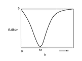
- FIG. 4 shows a magnetic field B generated by the magnet (11) with respect to a distance h along the center axis A of the magnet (11) from the center O of the magnet (11) (the upward direction along the coil center axis A is positive). Shows changes.
- the magnitude B of the magnetic field takes the maximum value Bmax, and decreases monotonously as the distance h increases.
- the magnitude B of the magnetic field is substantially constant in a plane orthogonal to the coil center axis A. In the following description, it is assumed that a downward magnetic field is generated along the coil center axis A by the magnet (11), but an upward magnetic field along the coil center axis A may be generated by the magnet (11).
- the separation tank (31) is preferably arranged away from the center O of the magnet (11) by a distance h where B ⁇ ⁇ B / ⁇ h takes a minimum value.
- the magnetic field generated by the magnet (11) has a vertical component (Bz) and a horizontal component (Bx).
- Bz vertical component
- Bx horizontal component
- the vertical direction is the z-axis
- the axis along the horizontal component of the magnetic field is the x-axis.
- the y-axis is taken as shown in FIG. 3 (the same coordinate system is adopted for FIGS. 6 and 7 described later).
- ⁇ 0 is the magnetic permeability in vacuum
- ⁇ i is the volume magnetic susceptibility of the first particle or the second particle (i is 1 or 2)
- ⁇ 0 is the volume magnetic susceptibility of the supporting liquid (21).
- the force F and the magnetic field B in this equation are vectors.
- the magnetic field generated by the magnet (11) is horizontal, that is, x in addition to the magnetic field gradient in the vertical direction, that is, the z-axis direction. It has an axial magnetic field gradient.
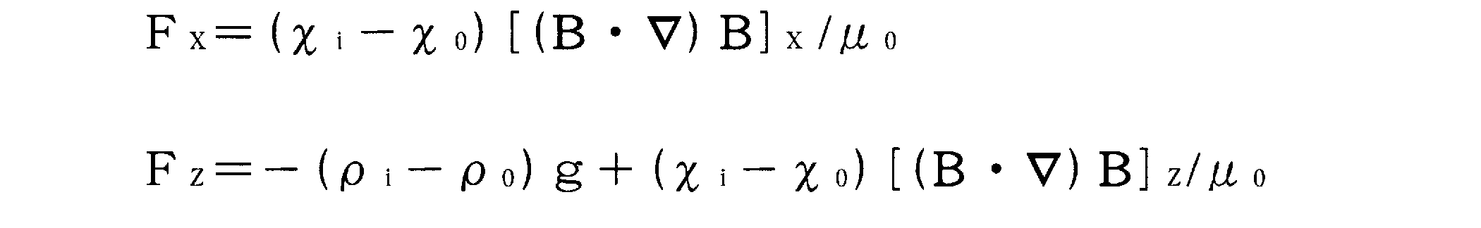
- the magnetic field gradient of the magnetic field generated by the magnet (11) has a vertical component and a horizontal component, that is, a z-direction component and an x-direction component. Therefore, in consideration of the effect of gravity, the force Fx in the x direction and the force Fz in the z direction acting on the first particle or the second particle in the support liquid 21 are as follows.
- g is the acceleration of gravity
- ⁇ i is the density (specific gravity) of the first particle or the second particle (i is 1 or 2)
- ⁇ 0 is the density (specific gravity) of the supporting liquid. .
- the z component Bz and the x component Bx of the magnetic field are negative.
- the x component of the magnetic field monotonously increases in the positive direction of the Bx axis ( ⁇ Bx / ⁇ x is positive) and monotonously increases in the positive direction of the z axis ( ⁇ Bx / ⁇ z is positive). Therefore, since [(B ⁇ ⁇ ) B] x in Fx in the above equation is negative, for both the first particle and the second particle, the supporting liquid (21) where ( ⁇ i ⁇ 0 ) ⁇ 0. ),
- the first particles and the second particles can be moved in the positive direction of the x-axis. That is, the first particles and the second particles introduced or introduced into the supporting liquid (21) through the hopper (33) are transferred from the hopper (33) to the wall (35) of the separation tank (31) or the suction pipe (51 ) (53).
- the supporting liquid (21) is selected so that ( ⁇ i ⁇ 0 )> 0. .
- the first particle or the second particle has z Negative force of the axis, that is, vertical downward force works.
- each of the first particles introduced through the hopper (33) follows a substantially similar locus in the support liquid (21) and moves toward the wall (35) of the separation tank (31). To do.
- Each of the second particles introduced through the hopper (33) also moves toward the wall (35) following a substantially similar trajectory in the support liquid (21).
- the trajectories of the first particles and the second particles in the support liquid (21) are different due to the difference between the density and the volume magnetic susceptibility of the first particles and the second particles.
- the particles and the second particles are eventually guided to different heights, positions, or locations in the z direction while moving in the x direction.
- the support liquid (21) is selected such that ( ⁇ i ⁇ 0 )> 0.
- paramagnetic liquid having a large absolute value of volume magnetic susceptibility
- paramagnetic liquids include aqueous solutions of paramagnetic inorganic salts such as manganese chloride, cobalt chloride, nickel chloride, ferrous chloride, cobalt nitrate, nickel nitrate, gadolinium nitrate, dysprosium nitrate and terbium nitrate.
- the supporting liquid may be an aqueous solution containing a plurality of types of paramagnetic inorganic salts.
- each of the first particles introduced through the hopper (33) descends while moving in the x direction in the support liquid (21), and the wall portion (35).
- the movement of the first particles in the z direction is restricted or restricted by the shelf plate (37).
- the length of the shelf plate (37) in the x direction is appropriately determined in consideration of the locus of the first particles in the support liquid (21).
- the end of the suction pipe (51) is disposed close to the upper surface of the shelf board (37), and the first particles on the shelf board (37) are attracted by the suction pipe (51) for collecting the first particles.
- the supporting liquid (21) sucked into the suction pipe (52) together with the first particles is preferably returned to the separation tank (31) after being separated from the first particles.
- the shelf plate (37) may be disposed substantially horizontally, and may be disposed, for example, slightly inclined so as to rise or descend toward the wall portion (35).
- each of the second particles introduced through the hopper (33) also descends while moving in the x direction in the support liquid (21), and the separation tank ( It reaches the bottom surface (39) of 31) and then moves on the bottom surface (39) of the separation tank (31) toward the wall portion (35).
- the bottom surface (39) restricts the movement of the second particles in the z direction.
- the bottom surface (39) may be disposed substantially horizontally, and may be disposed, for example, slightly inclined so as to rise or descend toward the wall portion (35).
- the end of the suction tube (53) is disposed close to the bottom surface (39) of the container (41), and the second particles on the bottom surface (39) are sucked into the suction tube (53) for collecting the second particles.
- the supporting liquid (21) sucked into the suction pipe (53) together with the second particles is preferably returned to the separation tank (31) after being separated from the second particles.
- a shelf plate may be added below the shelf plate (37), and the second particles may be moved horizontally on the shelf plate.
- the gradient magnetic field and / or the volume magnetic susceptibility and density of the supporting liquid (21) are adjusted.
- the first particles may move downward in the horizontal direction and reach the wall portion (35), where they may be suspended in the magnetic Archimedes state.
- Fz 0 is set in the supporting liquid (21) without providing the shelf (37) as described above. The first particles that are stably suspended at the position on the z-axis can be recovered.
- the shelf plate (37) is provided in accordance with the position floating by the magnetic Archimedes effect (slightly below the position). May be. Also, the second particles may move downward in the horizontal direction and reach the wall (35), where they may be suspended in a magnetic Archimedes state at a height different from that of the first particles.
- FIG. 6 is a cross-sectional view showing an outline of a mixture separation device according to a second embodiment of the separation method or separation device of the present invention.
- the mixture separation apparatus according to the second embodiment includes a first magnet (13) that levitates or floats the particles of the mixture in the support liquid (21), and horizontally mixes the particles of the mixture in the support liquid (21). It has a second magnet (15) for moving in the direction, and the gradient magnetic field applied to the support liquid (21) is composed of the gradient magnetic field of the first magnet (13) and the gradient magnetic field of the second magnet (15). Has been generated.
- the first magnet (13) is arranged below the substantially rectangular parallelepiped or box-shaped separation tank (31) in which the supporting liquid (21) is stored, and the vertical direction in which the size decreases monotonously in the vertical upward direction.
- a gradient magnetic field is applied to the support liquid (21) in the separation tank (31).
- the gradient magnetic field generated by the first magnet (13) is uniform or substantially uniform along the horizontal direction in the separation tank (31).
- the second magnet (15) is disposed on one end side of the separation tank (31) and generates a horizontal gradient magnetic field whose size decreases monotonously toward the other end side of the separation tank (31). Apply to the support liquid (21) in 31).
- the gradient magnetic field generated by the second magnet (15) is uniform or substantially uniform along the vertical direction in the separation tank (31).
- first magnet (13) and the second magnet (15) for example, a superconducting electromagnet using a solenoid coil is used, but a normal conducting electromagnet may be used. Description of the configuration for arranging the separation tank (31), the first magnet (13) and the second magnet (15) as shown in FIG. 6 will be omitted.
- a hopper (33) for charging the mixture is provided on one end side of the upper part of the separation tank (31), that is, on the second magnet (15) side.
- FIG. A pattern in which a mixture composed of particles (indicated by ⁇ ) and second particles (indicated by ⁇ ) is introduced into the supporting liquid (21) is illustrated.
- the supporting liquid (21) such that ( ⁇ i ⁇ 0 )> 0 Is selected.
- the first particles and the second particles descend while moving in the horizontal direction (x direction).
- the first particles and the second particles are in a magnetic Archimedes floating state, and the first particles are suspended near the top surface of the shelf (37).
- the second particles are floating near the bottom surface (39) of the separation tank (31).
- the floated first particles and second particles are individually recovered from the separation tank (31) using the suction pipes (51) and (53) as in the previous case.
- both the z-direction force and the x-direction force applied to the first and second particles in the support liquid (21) change.
- the force in the z direction applied to the first particles and the second particles can be adjusted.
- the force in the x direction applied to the first particles and the second particles can be adjusted.
- a force in the x direction may be intermittently applied to the first particle and the second particle by causing the current flowing through the second magnet (15) to intermittently flow, for example, in a pulse shape.
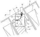
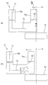
- FIG. 7 is a cross-sectional view showing an outline of a mixture separation device according to a third embodiment of the separation method or separation device of the present invention.
- a gradient magnetic field for separating particles of the mixture in the horizontal direction and separating them by type is generated using a superconducting bulk magnet (17).
- the superconducting bulk magnet (17) is formed in a cylindrical shape, and a substantially rectangular parallelepiped or box-shaped separation tank (31) is disposed on the circular magnetic pole end face.
- the separation tank (31) is arranged so that its longitudinal direction is along the radial direction of the magnetic pole end face of the magnet (17), and one end of the separation tank (31) is the central axis C of the superconducting bulk magnet (17). In the vicinity, the other end (wall portion (35)) of the separation tank (31) is disposed near the outer edge of the superconducting bulk magnet (17).
- the position of the separation tank (31) with respect to the superconducting bulk magnet (17) may be adjusted or changed as appropriate.
- a hopper (33) for charging the mixture is provided on one end of the upper part of the separation tank (31), that is, on the central axis C side of the superconducting bulk magnet (17).
- the pattern in which the mixture composed of the first particles (shown by ⁇ ) and the second particles (shown by ⁇ ) is put into the supporting liquid (21) is illustrated. Similar to the first and second embodiments, for both the first particle and the second particle, in addition to ( ⁇ i ⁇ 0 ) ⁇ 0, ( ⁇ i ⁇ 0 )> 0 and Such a support liquid (21) is selected.
- the superconducting bulk magnet (17) generates an axisymmetric magnetic field with respect to its central axis C.
- the magnitude of the magnetic field decreases with increasing distance from the magnetic pole end face of the magnet (17) along the vertical direction, or with increasing distance from the central axis C of the magnet (17) along the horizontal direction (radial direction). Therefore, the superconducting bulk magnet (17) applies the force Fx in the horizontal direction (x direction) and the force in the vertical direction (z direction) indicated by the above formula to the first and second particles in the support liquid (21).
- Fz is given.
- the first particle and the second particle are moved down in the horizontal direction (x direction) in the support liquid (21), and the position in the vertical direction (z direction) is reduced. These particles can be separated such that the first and second particles are different.
- the first particles are collected on the shelf plate (37) and collected from the separation tank (31) using the suction pipe (51).
- the second particles are collected on the bottom surface (39) of the separation tank (31) and collected from the separation tank (31) using the suction pipe (53).
- the first particles reach the wall portion (35) and float magnetically. It may be put into a state.
- the second particles may also reach the wall (35) and be in a magnetic Archimedean suspended state.
- the separation tank (31) of the mixture separation device of the third embodiment is formed in a cylindrical shape, and a hopper (33) is arranged at the center of the circular upper surface portion, and the center of the separation tank (31) or the hopper (33)
- the separation tank (31) may be disposed on the superconducting bulk magnet (17) so that the axis overlaps the central axis C of the superconducting bulk magnet (17).
- an annular shelf plate (37) is projected inwardly on the wall of the separation tank (31).
- the first particles and the second particles introduced into the supporting liquid (21) via the hopper (33) are contained in the supporting liquid (21).
- the second particle is finally the first particle. Located on the underside.
- the density of the second particles is very small (( ⁇ 2 ⁇ 0 ) ⁇ 0)
- the second particles remain floating on the liquid surface of the supporting liquid (21) and the wall portion (35). Will move towards.
- the first particle moves in the horizontal direction. It descends and reaches a predetermined height in the support liquid (21) to the shelf plate (37) or from the bottom surface (39) of the separation tank (31).
- the first particles introduced from the hopper (33) may move horizontally to the wall (35) of the separation tank (31) while being magnetically levitated on the surface of the support liquid (21). .
- the trajectory as illustrated in the figure is obtained for the first particle and the second particle, and the first particle is in a magnetic Archimedes floating state near the wall (35).
- the first to third embodiments have been described by taking, as an example, a mixture containing two kinds of particles having different substances. However, if at least one kind of particles is a paramagnetic substance or a diamagnetic substance, it is treated according to the present invention.
- grains contained in a mixture and the number of kinds are not limited.
- the shelf plate (37) and the suction pipes (51) and (53) are added in accordance with the types of particles contained in the mixture, and are arranged in consideration of the trajectories of these particles.
- the particles separated by type may be stably suspended in the separation tank (31) by the magnetic Archimedes effect without using a shelf.
- the ferromagnetic particles When ferromagnetic particles and paramagnetic or diamagnetic particles are contained in the mixture, the ferromagnetic particles are placed on the bottom surface of the separation tank (31) below the hopper (33). accumulate. The paramagnetic or diamagnetic particles move as described above to reach the shelf plate (37) (or float stably with the magnetic Archimedes effect at the wall (35)).
- the mixture can be separated by particle type using the present invention.
- the size of the particles contained in the mixture is not limited in principle. However, if it is too large, it is not convenient because it is inconvenient to handle and adversely affects the separation accuracy.
- the particle size should preferably be less than a few millimeters.
- the particles contained in the mixture may be powder or crushed material, and the shape of the particles contained in the mixture is not limited.
- a mixture treated using the present invention may be produced by crushing or grinding waste containing paramagnetic or diamagnetic metals.
- the mixture treated using the present invention may be obtained by treating a slurry produced by machining such as polishing or cutting.
- the mixture is introduced or introduced into the separation tank (31) using the hopper (33).
- the means for introducing the mixture into the separation tank (31) is particularly limited.
- the mixture may be introduced into the separation tank (31) by intermittently pouring the supporting liquid (21) in which the mixture is suspended into the separation tank (31).
- the particles may rise once and then move downward in the horizontal direction.
- the particles are collected from the separation tank (31) by type using the suction pipes (51) (53).
- the means for collecting the separated particles is particularly limited. Not. For example, a collection net like FIG. 4 of patent document 2 may be used. Further, it may be scraped out from the separation tank (31) separated using a scraper or the like.
- a magnet that applies a force in the y direction to the particles may be added to control the movement of the particles more precisely.
- the direction of the gradient magnetic field to be applied may be appropriately selected.
- the present invention can be used to separate a mixture containing a plurality of types of particles having different substances.
- the present invention is intended to separate specific types of particles formed of paramagnetic or diamagnetic materials from a mixture containing a plurality of types of particles of different substances. Can also be used.
- the mixture separation apparatus of the first to third embodiments can be used to separate and recover only the first particles from the mixture. In the case of using the present invention for such an application, the types of particles other than the particles to be separated and recovered may not be separated by type.
- the third particles are the second particles.
- the support liquid (21) it moves down in the horizontal direction and reaches the bottom surface (39) of the separation tank (31), and then the wall portion above the bottom surface (39) of the separation tank (31). May move towards (35) (the third particles are then collected in the suction tube (53) together with the second particles).
- Example 1 A superconducting magnet using a solenoid coil with a bore diameter of 100 mm is arranged with its coil central axis inclined at 30 degrees with respect to the vertical direction, and as shown in FIGS.
- the separation tank was made of transparent carbonate, and had a shape as shown in FIGS.
- the separation tank had a width of 40 mm, a length of 40 mm, and a height of 50 mm, and a shelf board having a width of 15 mm was projected from the bottom surface at a height of 25 mm.
- a mixture of glass (silica) particles (diamagnetic material) and alumina particles (diamagnetic material) was prepared (for the density and volume magnetic susceptibility of glass (silica) and alumina, see Table 1), and the above superconductivity After supplying electricity to the magnet to generate a magnetic field downward, it was dropped into the separation tank from the opposite side of the shelf. Both glass particles and alumina particles were spherical, and the particle size of these particles was approximately 1.5 mm.
- the maximum value of the magnetic field is 4T at the coil or magnet center, and the magnitude of the magnetic field in the x direction at the place closest to the coil center of the separation tank (corresponding to the right corner of the separation tank (31) shown in FIG. 2). Was 1T, and the magnitude of the magnetic field in the z direction was 2T.
- the particles of the charged mixture are moved down toward the supporting liquid while moving toward the wall on which the shelf is protruded, and as shown in the photograph of FIG.
- the particles (shining in FIG. 8) were collected on the shelf, and the alumina particles (white particles in FIG. 8) were collected on the bottom surface of the separation tank.
- the present invention can be used to separate glass particles or alumina particles from a mixture containing glass particles or alumina particles.
- FIGS. 9A and 9B are explanatory views for schematically explaining an outline of Example 2 corresponding to the above-described third embodiment.
- a separation tank (71) having a substantially U-shaped outer shape was produced using transparent carbonate as a material.
- the separation tank (71) had a length of 70 mm, a height of 60 mm, and a width of 2 mm, and a horizontal shelf (73) was provided at a position of 10 mm from the bottom.
- the upper ends of the extended portions (75a) and (75b) at both ends of the separation tank (71) are open, and a partition plate (77) connected to the shelf plate (73) is in one extended portion (75b). It was installed vertically.
- 50 wt% manganese chloride aqueous solution was put as a supporting liquid (79).
- a mixture of aluminum particles (paramagnetic material) and titanium particles (paramagnetic material) was prepared (see Table 1 for the density and volume magnetic susceptibility of aluminum and titanium), as shown in FIG. 9 (a). It put into the separation tank (71) arranged on the superconducting bulk magnet (81) through the opening of the extension part (75a). The aluminum particles were produced by crushing an aluminum lump, and the titanium particles were produced by crushing a titanium lump, and their size was approximately 1 mm.
- the superconducting bulk magnet (81) was cylindrical and its diameter was 60 mm.
- the superconducting bulk magnet (81) was magnetized using a solenoid type superconducting magnet, and the magnitude of the magnetic field at the center of the magnetic pole end face was about 3T.
- the separation tank (71) was arranged on the magnetic pole end face of the superconducting bulk magnet (81) so that the longitudinal direction thereof was along the radial direction of the superconducting bulk magnet (81). Further, the separation tank (71) is separated so that the central axis C of the superconducting bulk magnet (81) passes through the separation tank (71) slightly apart from the inner wall of the extending part (75a) of the separation tank (71) (about several mm).
- the vessel (71) was positioned relative to the superconducting bulk magnet (81).
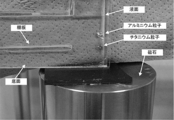
- the aluminum particles and titanium particles placed in the separation tank (71) have different heights due to the magnetic Archimedes effect on the inner wall of the extended portion (75a). Stable floating and accumulation. The floating height of the aluminum particles was above the height of the titanium particles.
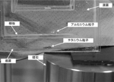
- the photograph in FIG. 10 is a photograph of this state. From this state, as shown in FIG. 9B, the separation tank (71) was slightly moved horizontally along the radial direction of the superconducting bulk magnet (81). The central axis C of the superconducting bulk magnet (81) moved to the outside of the separation tank (71) and was arranged to be separated from the outer surface of the separation tank (71) by about several mm.
- the separation tank (71) moved, the aluminum particles and titanium particles in the support liquid (79) dropped while moving to the extended portion (75b) side, as schematically shown in FIG. 9 (b). Then, as shown in the photograph of FIG. 11, the aluminum particles were placed on the shelf plate (73), and the titanium particles were placed on the bottom surface of the separation tank (71) almost below the aluminum particles. As described above, it was actually confirmed that a mixture of aluminum particles and titanium particles can be separated for each type using the present invention. It will also be easily understood from the results of Example 2 that the present invention can be used to separate aluminum particles or titanium particles from a mixture containing aluminum particles or titanium particles.
- Example 3 The same treatment as in Example 2 was performed, except that the mixture of glass particles and alumina particles used in Example 1 was used and that a 15 wt% cobalt chloride aqueous solution was used as the supporting liquid (79). .
- the glass particles and the alumina particles float in the magnetic Archimedes at different heights as shown in FIG. 9A, and then descend in the support liquid 79 as shown in FIG. 9B. Then, as shown in the photograph of FIG. 12A, glass particles were placed on the shelf plate (73), and alumina particles were placed on the bottom surface of the separation tank (71).
- Example 4 The same treatment as in Example 3 was performed, except that a cobalt nitrate 15 wt% aqueous solution was used as the support liquid (79).
- the glass particles and alumina particles float in the magnetic Archimedes at different heights as shown in FIG. 9 (a), and then move horizontally in the supporting liquid (79) as shown in FIG. 9 (b).
- glass particles were placed on the shelf plate (73), and alumina particles were placed on the bottom surface of the separation tank (71).
- Example 5 The same treatment as in Example 3 was performed except that a nickel chloride 20 wt% aqueous solution was used as the support liquid (79).
- the glass particles and alumina particles float in the magnetic Archimedes at different heights as shown in FIG. 9 (a), and then move horizontally in the supporting liquid (79) as shown in FIG. 9 (b).
- the glass particles were arranged on the shelf plate (73), and the alumina particles were arranged on the bottom surface of the separation tank (71).
- Example 6 The same treatment as in Example 3 was performed except that a 15 wt% gadolinium nitrate aqueous solution was used as the supporting liquid (79).
- the glass particles and alumina particles float in the magnetic Archimedes at different heights as shown in FIG. 9 (a), and then move horizontally in the supporting liquid (79) as shown in FIG. 9 (b).
- glass particles were placed on the shelf plate (73), and alumina particles were placed on the bottom surface of the separation tank (71).
- Example 7 The same treatment as in Example 3 was performed except that a 15 wt% dysprosium nitrate aqueous solution was used as the supporting liquid (79).
- the glass particles and alumina particles float in the magnetic Archimedes at different heights as shown in FIG. 9 (a), and then move horizontally in the supporting liquid (79) as shown in FIG. 9 (b).
- glass particles were placed on the shelf plate (73), and alumina particles were placed on the bottom surface of the separation tank (71) (FIG. 13 (b)).
- a plastic thin plate is inserted between the separation tank (71) and the superconducting bulk magnet (81) (the same applies to FIGS. 13 (c) and 14 (c)).
- Example 8 The same treatment as in Example 3 was performed, except that a 15 wt% aqueous solution of terbium nitrate was used as the supporting liquid (79).
- the glass particles and alumina particles float in the magnetic Archimedes at different heights as shown in FIG. 9 (a), and then move horizontally in the supporting liquid (79) as shown in FIG. 9 (b).
- glass particles were placed on the shelf plate (73), and alumina particles were placed on the bottom surface of the separation tank (71).
- Example 9 The same treatment as in Example 3 was performed, except that a nickel nitrate 20 wt% aqueous solution was used as the support liquid (79).
- the glass particles and alumina particles float in the magnetic Archimedes at different heights as shown in FIG. 9 (a), and then move horizontally in the supporting liquid (79) as shown in FIG. 9 (b).
- glass particles were placed on the shelf plate (73), and alumina particles were placed on the bottom surface of the separation tank (71).
- Example 10 The same treatment as in Example 3 was performed except that a 10 wt% ferrous chloride aqueous solution was used as the supporting liquid (79).
- the glass particles and alumina particles float in the magnetic Archimedes at different heights as shown in FIG. 9 (a), and then move horizontally in the supporting liquid (79) as shown in FIG. 9 (b).
- the glass particles were arranged on the shelf plate (73), and the alumina particles were arranged on the bottom surface of the separation tank (71).
- Example 11 A point of using a mixture prepared by adding red glass particles having a maximum size of about 1 mm to the mixture of glass particles and alumina particles used in Example 1, and a 15 wt% manganese chloride aqueous solution as a supporting liquid (79) The same treatment as in Example 2 was performed except that the point was used.
- the glass particles (and red glass particles) and alumina particles float in the magnetic Archimedes at different heights as shown in FIG. 9 (a), and then in the supporting liquid (79) as shown in FIG. 9 (b).
- the glass particles and the red glass particles are arranged on the shelf plate (73), and the alumina particles are separated from the separation tank (71). Arranged on the bottom.
- Example 1 and Example 2 an aqueous manganese chloride solution was used as the supporting liquid, but according to Examples 3 to 10, cobalt chloride, cobalt nitrate, nickel chloride, gadolinium nitrate, dysprosium nitrate, terbium nitrate, nickel nitrate, It was actually confirmed that an aqueous solution of ferrous chloride can also be used as the support liquid of the present invention.
- the supporting liquid may be an aqueous solution containing a plurality of types of paramagnetic inorganic salts selected from manganese chloride, cobalt chloride, cobalt nitrate, nickel chloride, gadolinium nitrate, dysprosium nitrate, terbium nitrate, nickel nitrate and ferrous chloride. It will be easily understood by those skilled in the art that an aqueous solution containing a paramagnetic inorganic salt (for example, gadolinium chloride) other than the paramagnetic inorganic salt used in the examples can be used as the supporting liquid.
- a paramagnetic inorganic salt for example, gadolinium chloride
- Example 11 When Examples 1 and 2 are compared with Example 11, in the present invention, the paramagnetic inorganic salt in the supporting liquid is changed according to the mixture to be treated (substance constituting), the gradient magnetic field to be applied, the shape of the separation tank, and the like. It can be appreciated that the concentration may be adjusted.
- the particles contained in the mixture are separated for each type of substance using the magnetic Archimedes effect by a gradient magnetic field having a vertical gradient
- Experimental Examples 3 and 6 one type of particles is stably suspended using the magnetic Archimedes effect by a gradient magnetic field having a vertical gradient.
- the particles are not moved in the horizontal direction as in the above Examples, but the equipment employed in Experimental Examples 1 to 6 can be easily understood from the description regarding the first to third embodiments. It is possible to move the particles in the horizontal direction by changing the configuration, for example, by applying a gradient magnetic field having a horizontal component magnetic field gradient. Those who have ordinary knowledge in this field will easily understand that the results and knowledge obtained from Experimental Examples 1 to 6 can be applied or used in the present invention.
- Example 1 A mixture containing aluminum particles, titanium particles, alumina particles, and glass (silica) particles was put into a 50 wt% manganese chloride aqueous solution placed in a bottomed cylindrical glass container, and a vertically upward gradient magnetic field was applied. The size of various particles was set to about 1 mm (the same applies to other experimental examples).
- a cylindrical superconducting bulk magnet magnetized with a solenoid type superconducting magnet is used, and a glass container containing a manganese chloride aqueous solution containing the mixture is placed in the superconducting bulk magnet. (See the photograph in FIG. 17. In FIG. 17, the glass container is placed on the superconducting bulk magnet through black paper for photography).
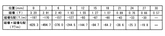
- FIG. 15 shows the magnitude of the magnetic field applied by the superconducting bulk magnet used in Experimental Example 1, and the distribution of the product of the magnitude of the magnetic field and the magnetic field gradient in the z direction.
- FIG. 16 shows the distance from the end face of the superconducting bulk magnet, the magnetic field, the magnetic field gradient in the z direction, and the magnetic field ⁇ magnetic field gradient values.
- a mixture containing aluminum particles, titanium particles, alumina particles, and glass particles can be separated by particle type, and a mixture containing diamagnetic particles and paramagnetic particles can be separated by particle type.
- the present invention can be used to separate any of these particles from a mixture containing aluminum particles, titanium particles, alumina particles and / or glass particles, and from a mixture containing diamagnetic particles and paramagnetic particles. It can be understood from the results of Experimental Example 1 that either diamagnetic particles or paramagnetic particles can be separated.
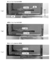
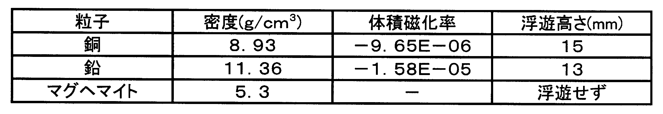
- Example 2 A mixture containing copper particles (diamagnetic material), lead particles (diamagnetic material), and maghemite ( ⁇ -Fe 2 O 3 ) particles (ferromagnetic material) was put in the same glass container as in Experimental Example 1. A 50 wt% manganese chloride aqueous solution was added, and the same gradient magnetic field as in Experimental Example 1 was applied vertically upward. Table 2 shows the density, volume magnetic susceptibility (excluding maghemite), and floating position for these particles.
- maghemite which is a ferromagnetic material
- maghemite particles are attracted to the superconducting bulk magnet and deposited on the bottom of the glass container.
- the copper particles and lead particles floated and separated at different heights.
- a mixture containing copper particles, lead particles or maghemite particles can be separated for each type, a mixture containing copper particles, lead particles and maghemite particles can be separated for each type, and further a diamagnetic material It can be understood from the results of Experimental Example 2 that the mixture containing particles and ferromagnetic particles can be separated for each type of particles. Furthermore, the present invention can be used to separate copper particles or lead particles from a mixture containing maghemite particles in addition to copper particles or lead particles, and from a mixture containing diamagnetic particles and ferromagnetic particles. It can be understood from the results of Experimental Example 2 that the particles can be separated.
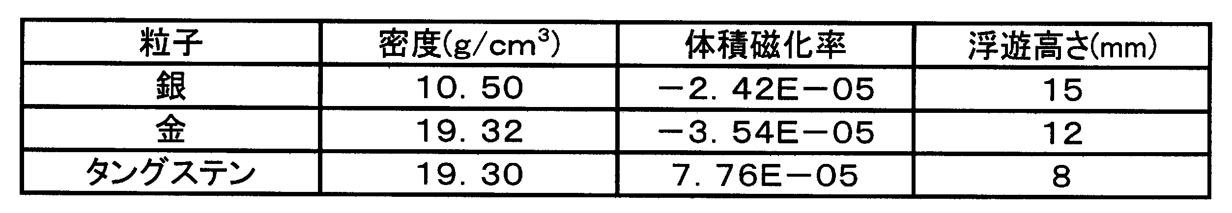
- Example 3 Silver particles (diamagnetic material), gold particles (diamagnetic material), and tungsten particles (paramagnetic material) were individually charged into a 50 wt% aqueous solution of manganese chloride in the same glass container as in Experimental Example 1. The same gradient magnetic field was applied vertically upward. Table 3 shows the density, volume magnetic susceptibility, and floating position of these particles.
- a mixture containing tungsten particles, silver particles or gold particles can be separated for each type of particles, a mixture containing tungsten particles, silver particles and gold particles can be separated for each type, and further high density It can be understood from the results of Experimental Example 3 that the mixture containing the particles can be separated for each type of particles. Furthermore, it can be understood from the results of Experimental Example 3 that any of these particles can be separated from a mixture containing tungsten particles, silver particles, or gold particles by using the present invention, and that high-density particles can be separated from the mixture. Is done.
- Example 4 The mixture containing aluminum particles and titanium particles was put into an aqueous manganese chloride solution in the same glass container as in Experimental Example 1, and the same gradient magnetic field as in Experimental Example 1 was applied vertically upward.
- the concentration of the aqueous manganese chloride solution was changed to change the floating positions of the aluminum particles and the titanium particles.
- Table 4 shows the concentration of the aqueous manganese chloride solution and the corresponding floating position of the particles.
- the concentration of the paramagnetic inorganic salt is changed in the present invention. It can be understood from the results of Experimental Example 4 that the trajectory and collection location of the particles can be adjusted or controlled.
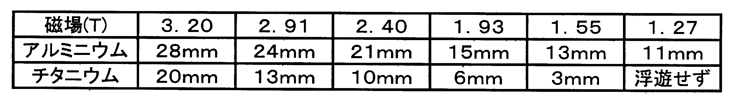
- Example 5 A mixture containing aluminum particles and titanium particles was put into a 50 wt% manganese chloride aqueous solution in the same glass container as in Example 1, and the same magnetic field as in Experimental Example 1 was applied vertically upward.
- the magnetic field applied to the particles and the magnetic field gradient were changed by changing the position of the glass container in the vertical direction. Table 5 shows the magnitude of the magnetic field on the bottom surface of the glass container and the floating position (from the bottom surface of the glass container) of the particles corresponding to each set of magnetic field and magnetic field gradient.
- Example 6 Silica particles were put into a 25 wt% ferrous chloride aqueous solution in the same glass container as in Experimental Example 1, and the same gradient magnetic field as in Experimental Example 1 was applied vertically upward. In this case, the silica particles stably floated at a position 16 mm from the end face of the superconducting bulk magnet.
Landscapes
- Physics & Mathematics (AREA)
- Fluid Mechanics (AREA)
- Separation Of Solids By Using Liquids Or Pneumatic Power (AREA)
Abstract
Description
ボア径100mmのソレノイドコイルを用いた超伝導磁石を、そのコイル中心軸を鉛直方向に対して30度傾斜した状態に配置し、図1及び図2に示すように、超伝導磁石の内側空間に、支持液体として50wt%塩化マンガン水溶液を貯蔵した分離槽を配置した。分離槽は、透明なカーボネートで形成されており、図1乃至図3に示すような形状を有していた。分離槽の幅は40mm、長さは40mm、高さは50mmであり、幅15mmの棚板が底面から高さ25mmの位置に突設された。
図9(a)及び(b)は、上述の第3実施形態に対応した実施例2の概要を模式的に説明する説明図である。略U字状の外形を有する分離槽(71)を、透明なカーボネートを材料として作製した。分離槽(71)の長さは70mm、高さは60mm、幅は2mmであり、底面から高さ10mmの位置に水平な棚板(73)が設けられた。分離槽(71)の両端の延出部分(75a)(75b)の上端は開放しており、一方の延出部分(75b)内には、棚板(73)と繋がる仕切り板(77)が鉛直に設けられた。分離槽(71)内には、支持液体(79)として50wt%塩化マンガン水溶液が入れられた。
実施例1で用いたガラス粒子とアルミナ粒子からなる混合物を用いた点と、支持液体(79)として塩化コバルト15wt%水溶液を用いた点とを除いて、実施例2と同様な処理を行った。ガラス粒子とアルミナ粒子は、図9(a)に示すように夫々異なる高さに磁気アルキメデス浮遊した後、図9(b)に示すように、支持液体(79)中を降下しつつ水平方向(径方向)に移動し、その後、図12(a)の写真に示すように、ガラス粒子が棚板(73)上に配置され、アルミナ粒子が分離槽(71)の底面に配置された。
支持液体(79)として硝酸コバルト15wt%水溶液を用いた点を除いて、実施例3と同様な処理を行った。ガラス粒子とアルミナ粒子は、図9(a)に示すように夫々異なる高さに磁気アルキメデス浮遊した後、図9(b)に示すように、支持液体(79)中を降下しつつ水平方向に移動し、その後、図12(b)の写真に示すように、ガラス粒子が棚板(73)上に配置され、アルミナ粒子が分離槽(71)の底面に配置された。
支持液体(79)として塩化ニッケル20wt%水溶液を用いた点を除いて、実施例3と同様な処理を行った。ガラス粒子とアルミナ粒子は、図9(a)に示すように夫々異なる高さに磁気アルキメデス浮遊した後、図9(b)に示すように、支持液体(79)中を降下しつつ水平方向に移動し、その後、図12(c)の写真に示すように、ガラス粒子が棚板(73)上に配置され、アルミナ粒子が分離槽(71)の底面に配置された。
支持液体(79)として硝酸ガドリニウム15wt%水溶液を用いた点を除いて、実施例3と同様な処理を行った。ガラス粒子とアルミナ粒子は、図9(a)に示すように夫々異なる高さに磁気アルキメデス浮遊した後、図9(b)に示すように、支持液体(79)中を降下しつつ水平方向に移動し、その後、図13(a)の写真に示すように、ガラス粒子が棚板(73)上に配置され、アルミナ粒子が分離槽(71)の底面に配置された。
支持液体(79)として硝酸ジスプロシウム15wt%水溶液を用いた点を除いて、実施例3と同様な処理を行った。ガラス粒子とアルミナ粒子は、図9(a)に示すように夫々異なる高さに磁気アルキメデス浮遊した後、図9(b)に示すように、支持液体(79)中を降下しつつ水平方向に移動し、その後、図13(b)の写真に示すように、ガラス粒子が棚板(73)上に配置され、アルミナ粒子が分離槽(71)の底面に配置された(図13(b)では、分離槽(71)と超伝導バルク磁石(81)の間にプラスチック薄板が挿入されている。図13(c)及び図14(c)も同様)。
支持液体(79)として硝酸テルビウム15wt%水溶液を用いた点を除いて、実施例3と同様な処理を行った。ガラス粒子とアルミナ粒子は、図9(a)に示すように夫々異なる高さに磁気アルキメデス浮遊した後、図9(b)に示すように、支持液体(79)中を降下しつつ水平方向に移動し、その後、図13(c)の写真に示すように、ガラス粒子が棚板(73)上に配置され、アルミナ粒子が分離槽(71)の底面に配置された。
支持液体(79)として硝酸ニッケル20wt%水溶液を用いた点を除いて、実施例3と同様な処理を行った。ガラス粒子とアルミナ粒子は、図9(a)に示すように夫々異なる高さに磁気アルキメデス浮遊した後、図9(b)に示すように、支持液体(79)中を降下しつつ水平方向に移動し、その後、図14(a)の写真に示すように、ガラス粒子が棚板(73)上に配置され、アルミナ粒子が分離槽(71)の底面に配置された。
支持液体(79)として塩化第一鉄10wt%水溶液を用いた点を除いて、実施例3と同様な処理を行った。ガラス粒子とアルミナ粒子は、図9(a)に示すように夫々異なる高さに磁気アルキメデス浮遊した後、図9(b)に示すように、支持液体(79)中を降下しつつ水平方向に移動し、その後、図14(b)の写真に示すように、ガラス粒子が棚板(73)上に配置され、アルミナ粒子が分離槽(71)の底面に配置された。
実施例1で用いたガラス粒子とアルミナ粒子からなる混合物に、大きさが最大で1mm程度の赤ガラス粒子を加えて調整した混合物を用いた点と、支持液体(79)として塩化マンガン15wt%水溶液を用いた点とを除いて、実施例2と同様な処理を行った。ガラス粒子(及び赤ガラス粒子)とアルミナ粒子は、図9(a)に示すように夫々異なる高さに磁気アルキメデス浮遊した後、図9(b)に示すように、支持液体(79)中を降下しつつ水平方向に移動し、その後、図14(c)の写真に示すように、ガラス粒子と赤ガラス粒子とが棚板(73)上に配置され、アルミナ粒子が分離槽(71)の底面に配置された。
アルミニウム粒子、チタニウム粒子、アルミナ粒子、及びガラス(シリカ)粒子を含む混合物を、有底円筒状のガラス製容器に入れた50wt%塩化マンガン水溶液に投入し、鉛直上向きの勾配磁場を印加した。各種粒子の大きさは、略1mmにされた(その他の実験例でも同様)。勾配磁場の印加には、ソレノイド型超伝導磁石を用いて着磁された円柱状の超伝導バルク磁石を使用し、混合物が入れられた塩化マンガン水溶液が入ったガラス製容器を、超伝導バルク磁石の磁極端面の中央に載置した(図17の写真を参照のこと。図17では、ガラス製容器は、写真撮影用の黒色の紙を介して超伝導バルク磁石に載置されている)。

銅粒子(反磁性体)、鉛粒子(反磁性体)、及びマグへマイト(γ-Fe2O3)粒子(強磁性体)を含む混合物を、実験例1と同じガラス製容器に入れた50wt%塩化マンガン水溶液に投入し、実験例1と同じ勾配磁場を鉛直上向きに印加した。表2に、これらの粒子について、密度、体積磁化率(マグへマイトを除く)及び浮遊位置を示す。50wt%塩化マンガン水溶液の磁化は強磁性体であるマグへマイトの磁化と比較して非常に小さいので、マグへマイト粒子は、超伝導バルク磁石に吸引されて、ガラス製容器の底部に堆積したが、銅粒子及び鉛粒子は、異なる高さに浮遊し、分離した。
銀粒子(反磁性体)、金粒子(反磁性体)及びタングステン粒子(常磁性体)を、実験例1と同じガラス製容器に入れた50wt%塩化マンガン水溶液に個別に投入し、実験例1と同じ勾配磁場を鉛直上向きに印加した。表3に、これらの粒子について、密度、体積磁化率及び浮遊位置を示す。
アルミニウム粒子及びチタニウム粒子を含む混合物を、実験例1と同じガラス製容器に入れた塩化マンガン水溶液に投入し、実験例1と同じ勾配磁場を鉛直上向きに印加した。実験例4では、塩化マンガン水溶液の濃度を変化させて、アルミニウム粒子及びチタニウム粒子の浮揚位置を変化させた。表4に、塩化マンガン水溶液の濃度と、それに対応した粒子の浮遊位置とを示す。

アルミニウム粒子及びチタニウム粒子を含む混合物を、実施例1と同じガラス製容器に入れた50wt%塩化マンガン水溶液に投入し、実験例1と同じ磁場を鉛直上向きに印加した。実験例5では、ガラス製容器の位置を鉛直方向に変化させることで、粒子に印加する磁場と磁場勾配とを変化させた。表5に、ガラス製容器の底面における磁場大きさと、磁場及び磁場勾配の各組に対応した粒子の(ガラス製容器の底面からの)浮遊位置とを示す。
シリカ粒子を、実験例1と同じガラス製容器に入れた25wt%塩化第一鉄水溶液に投入し、実験例1と同じ勾配磁場を鉛直上向きに印加した。この場合、超伝導バルク磁石の端面から16mmの位置にシリカ粒子が安定浮揚した。
(13) 第1磁石
(15) 第2磁石
(17) 超伝導バルク磁石
(21) 支持液体
(31) 分離槽
(33) ホッパー
(37) 棚板
(39) 底面
(41) 容器
(51) 吸引管
(53) 吸引管
Claims (14)
- 一方の種類の粒子が常磁性体又は反磁性体である少なくとも2種類の粒子を含む混合物を種類ごとに分離する、或いは、前記混合物から前記一方の種類の粒子を分離する混合物の分離方法であって、
分離槽に貯蔵された支持液体に、磁場勾配が鉛直成分と水平成分とを有する磁場を印加する工程と、
前記磁場が印加された前記支持液体に前記混合物を入れて、前記磁場を用いて、前記一方の種類の粒子を水平方向に移動させつつ、前記支持液体中にて前記分離槽の底面から所定の高さに位置するように前記一方の種類の粒子を誘導する工程、又は、前記磁場が印加された前記支持液体に前記混合物を入れて、前記磁場を用いて、前記一方の種類の粒子を前記支持液体の液面に磁気浮揚させると共に水平方向に移動させる工程と、
前記所定の高さ又は前記支持液体の液面に配置された前記一方の種類の粒子を回収する工程とを含んでおり、
前記少なくとも2種類の粒子の中の他方の種類の粒子は、前記分離槽の底面と前記支持液体の液面の間にて、鉛直方向について前記一方の種類の粒子と異なる位置に配置される混合物の分離方法。 - 前記分離槽には、略水平な棚板が配設されており、前記一方の種類の粒子は、前記支持液体中を降下して前記棚板に載置される、請求項1に記載の混合物の分離方法。
- 前記一方の種類の粒子は、前記支持液体中にて前記所定の高さで安定に磁気浮揚する、請求項1に記載の混合物の分離方法。
- 前記磁場は、超伝導バルク磁石を、又はコイル中心軸が鉛直方向に対して傾けられたソレノイドコイルを有する磁場生成手段を用いて生成される、請求項1乃至3の何れかに記載の混合物の分離方法。
- 前記磁場は、第1磁場生成手段により生成された第1磁場と、第2磁場生成手段により生成された第2磁場とを合成したものであり、前記第1磁場の磁場勾配は鉛直方向を、前記第2磁場の磁場勾配は水平方向を向いている、請求項1乃至3の何れかに記載の混合物の分離方法。
- 前記支持液体は、少なくとも一種の常磁性無機塩を含む水溶液である、請求項1乃至5の何れかに記載の混合物の分離方法。
- 前記支持液体は、塩化マンガン、塩化コバルト、塩化ニッケル、塩化第一鉄、硝酸コバルト、硝酸ニッケル、硝酸ガドリニウム、硝酸ジスプロシウム及び硝酸テルビウムからなる群から選択された少なくとも一種の常磁性無機塩を含む水溶液である、請求項6に記載の混合物の分離方法。
- 一方の種類の粒子が常磁性体又は反磁性体である少なくとも2種類の粒子を含む混合物を種類ごとに分離する、或いは、前記混合物から前記一方の種類の粒子を分離する混合物の分離装置であって、
支持液体を貯蔵する分離槽と、
磁場勾配が鉛直成分と水平成分とを有する磁場を前記支持液体に印加する磁場生成手段と、
前記分離槽の一端側に設けられており、前記混合物を前記支持液体に導入する導入手段と、
前記分離槽の他端側に設けられており、前記一方の種類の粒子を回収する回収手段とを備えており、
前記導入手段を介して、前記磁場が印加された前記支持液体に前記混合物が導入されると、前記一方の種類の粒子は、前記磁場によって、前記分離槽の他端側に移動しつつ、前記支持液体中にて前記分離槽の底面から所定の高さに位置するように誘導され、又は、前記一方の種類の粒子は、前記磁場によって、前記支持液体の液面に磁気浮揚して、前記分離槽の他端側に移動し、
前記回収手段は、前記所定の高さ又は前記支持液体の液面に配置された前記一方の種類の粒子を前記分離槽から回収し、
前記少なくとも2種類の粒子の中の他方の種類の粒子は、前記分離槽の底面と前記支持液体の液面の間にて、鉛直方向について前記一方の種類の粒子と異なる位置に配置される混合物の分離装置。 - 前記分離槽には、略水平な棚板が配設されており、前記一方の種類の粒子は、前記支持液体中を降下して前記棚板に載置される、請求項8に記載の分離装置。
- 前記一方の種類の粒子は、前記支持液体中にて前記所定の高さで安定に磁気浮揚する、請求項8に記載の分離装置。
- 前記磁場生成手段は、超伝導バルク磁石を、又はコイル中心軸が鉛直方向に対して傾けられたソレノイドコイルを有する電磁石である、請求項8乃至10の何れかに記載の分離装置。
- 前記磁場生成手段は、第1磁場を生成する第1磁石と、第2磁場を生成する第2磁石とを含んでおり、前記磁場は、前記第1磁場と前記第2磁場を合成したものであり、前記第1磁場の磁場勾配は鉛直方向を、前記第2磁場の磁場勾配は水平方向を向いている、請求項8乃至10の何れかに記載の分離装置。
- 前記支持液体は、少なくとも一種の常磁性無機塩を含む水溶液である、請求項8乃至12の何れかに記載の混合物の分離装置。
- 前記支持液体は、塩化マンガン、塩化コバルト、塩化ニッケル、塩化第一鉄、硝酸コバルト、硝酸ニッケル、硝酸ガドリニウム、硝酸ジスプロシウム及び硝酸テルビウムからなる群から選択された少なくとも一種の常磁性無機塩を含む水溶液である、請求項13に記載の混合物の分離装置。
Priority Applications (3)
| Application Number | Priority Date | Filing Date | Title |
|---|---|---|---|
| EP12749423.5A EP2679310A4 (en) | 2011-02-23 | 2012-02-21 | METHOD AND DEVICE FOR SEPARATING MIXTURES |
| JP2013501069A JP5403306B2 (ja) | 2011-02-23 | 2012-02-21 | 混合物の分離方法及び装置 |
| US14/001,002 US9308536B2 (en) | 2011-02-23 | 2012-02-21 | Method and apparatus for separation of mixture |
Applications Claiming Priority (2)
| Application Number | Priority Date | Filing Date | Title |
|---|---|---|---|
| JP2011037013 | 2011-02-23 | ||
| JP2011-037013 | 2011-02-23 |
Publications (1)
| Publication Number | Publication Date |
|---|---|
| WO2012115100A1 true WO2012115100A1 (ja) | 2012-08-30 |
Family
ID=46720877
Family Applications (1)
| Application Number | Title | Priority Date | Filing Date |
|---|---|---|---|
| PCT/JP2012/054116 Ceased WO2012115100A1 (ja) | 2011-02-23 | 2012-02-21 | 混合物の分離方法及び装置 |
Country Status (4)
| Country | Link |
|---|---|
| US (1) | US9308536B2 (ja) |
| EP (1) | EP2679310A4 (ja) |
| JP (1) | JP5403306B2 (ja) |
| WO (1) | WO2012115100A1 (ja) |
Cited By (2)
| Publication number | Priority date | Publication date | Assignee | Title |
|---|---|---|---|---|
| US8558736B2 (en) | 2009-02-22 | 2013-10-15 | Trimble Navigation Limited | GNSS signal processing methods and apparatus with ionospheric filters |
| WO2014046164A1 (ja) * | 2012-09-20 | 2014-03-27 | 宇部興産株式会社 | 混合物の分離方法及び分離装置 |
Families Citing this family (7)
| Publication number | Priority date | Publication date | Assignee | Title |
|---|---|---|---|---|
| EP2692447B1 (en) * | 2011-03-31 | 2017-02-22 | Ube Industries, Ltd. | Mixture separation method and separation device |
| US20130298731A1 (en) * | 2012-05-08 | 2013-11-14 | Qingwen Zhang | Method for efficient extraction of gold from gold ores utilizing macro quantum resonance effect |
| US10928404B2 (en) | 2014-02-26 | 2021-02-23 | The Brigham And Women's Hospital, Inc. | System and method for cell levitation and monitoring |
| CN106890728B (zh) * | 2017-03-07 | 2018-10-26 | 广东顺德工业设计研究院(广东顺德创新设计研究院) | 磁性颗粒粒径分选方法 |
| CN112275776A (zh) * | 2020-10-12 | 2021-01-29 | 王如梦 | 一种环保型垃圾处理再利用装置 |
| KR20240068442A (ko) | 2022-11-10 | 2024-05-17 | 한국전기연구원 | 플라스틱 분류 장치 |
| WO2026038949A1 (en) * | 2024-08-13 | 2026-02-19 | Myneip B.V. | Splitter plate for magnetic density separation |
Citations (13)
| Publication number | Priority date | Publication date | Assignee | Title |
|---|---|---|---|---|
| JPS5753258A (en) * | 1980-09-16 | 1982-03-30 | Tohoku Metal Ind Ltd | Separator for magnetic powder |
| JPS6039319U (ja) * | 1983-08-24 | 1985-03-19 | 三菱製鋼磁材株式会社 | 湿式磁気分離機 |
| JPS6178375A (ja) * | 1984-09-25 | 1986-04-21 | Hitachi Ltd | 水生細菌の分離回収方法 |
| JPS63307158A (ja) * | 1987-06-09 | 1988-12-14 | Mitsubishi Electric Corp | 酸化物超電導体の製造方法 |
| JPS63315159A (ja) * | 1987-06-17 | 1988-12-22 | Hitachi Ltd | 超電導体の選別方法 |
| JPS6422359A (en) * | 1987-07-16 | 1989-01-25 | Fujikura Ltd | Production of superconductive material |
| JPS6430659A (en) * | 1987-07-24 | 1989-02-01 | Sumitomo Heavy Industries | Screening method for superconductive material |
| JPS6434454A (en) * | 1987-06-24 | 1989-02-03 | Gen Atomic Co | Method and device for increasing superconductive substance |
| JPS6475036A (en) * | 1987-09-16 | 1989-03-20 | Honda Motor Co Ltd | Temperature difference separator |
| JPH01304060A (ja) * | 1988-02-02 | 1989-12-07 | Koujiyundo Kagaku Kenkyusho:Kk | 超伝導粉末の分離方法とその装置 |
| JP2002059026A (ja) | 2000-08-23 | 2002-02-26 | Japan Society For The Promotion Of Science | 磁気アルキメデス効果によるプラスチック混合物の分別方法 |
| JP2010524663A (ja) | 2007-04-18 | 2010-07-22 | トーマス エイ. バレリオ、 | リサイクル材料を選別して処理する方法およびシステム |
| WO2011049229A1 (ja) * | 2009-10-22 | 2011-04-28 | Jfeスチール株式会社 | 強磁性体の分離装置 |
Family Cites Families (6)
| Publication number | Priority date | Publication date | Assignee | Title |
|---|---|---|---|---|
| DE3880973T2 (de) * | 1987-06-09 | 1994-01-27 | Mitsubishi Electric Corp | Verfahren zur herstellung von supraleitern auf oxidbasis. |
| US5762204A (en) * | 1995-12-05 | 1998-06-09 | Industrial Technology Research Institute | Ferrofluid sink/float separators for separating nonmagnetic materials of different densities |
| US6994219B2 (en) * | 2004-01-26 | 2006-02-07 | General Electric Company | Method for magnetic/ferrofluid separation of particle fractions |
| JP2010517758A (ja) * | 2007-02-07 | 2010-05-27 | コーニンクレッカ フィリップス エレクトロニクス エヌ ヴィ | 磁性粒子の分離手段 |
| NL2001322C2 (nl) * | 2008-02-27 | 2009-08-31 | Univ Delft Tech | Werkwijze en inrichting voor het scheiden van vaste deeltjes met een onderling dichtheidsverschil. |
| NL2010515C2 (en) * | 2013-03-25 | 2014-09-29 | Univ Delft Tech | Magnet and device for magnetic density separation including magnetic field correction. |
-
2012
- 2012-02-21 EP EP12749423.5A patent/EP2679310A4/en not_active Withdrawn
- 2012-02-21 JP JP2013501069A patent/JP5403306B2/ja not_active Expired - Fee Related
- 2012-02-21 US US14/001,002 patent/US9308536B2/en not_active Expired - Fee Related
- 2012-02-21 WO PCT/JP2012/054116 patent/WO2012115100A1/ja not_active Ceased
Patent Citations (13)
| Publication number | Priority date | Publication date | Assignee | Title |
|---|---|---|---|---|
| JPS5753258A (en) * | 1980-09-16 | 1982-03-30 | Tohoku Metal Ind Ltd | Separator for magnetic powder |
| JPS6039319U (ja) * | 1983-08-24 | 1985-03-19 | 三菱製鋼磁材株式会社 | 湿式磁気分離機 |
| JPS6178375A (ja) * | 1984-09-25 | 1986-04-21 | Hitachi Ltd | 水生細菌の分離回収方法 |
| JPS63307158A (ja) * | 1987-06-09 | 1988-12-14 | Mitsubishi Electric Corp | 酸化物超電導体の製造方法 |
| JPS63315159A (ja) * | 1987-06-17 | 1988-12-22 | Hitachi Ltd | 超電導体の選別方法 |
| JPS6434454A (en) * | 1987-06-24 | 1989-02-03 | Gen Atomic Co | Method and device for increasing superconductive substance |
| JPS6422359A (en) * | 1987-07-16 | 1989-01-25 | Fujikura Ltd | Production of superconductive material |
| JPS6430659A (en) * | 1987-07-24 | 1989-02-01 | Sumitomo Heavy Industries | Screening method for superconductive material |
| JPS6475036A (en) * | 1987-09-16 | 1989-03-20 | Honda Motor Co Ltd | Temperature difference separator |
| JPH01304060A (ja) * | 1988-02-02 | 1989-12-07 | Koujiyundo Kagaku Kenkyusho:Kk | 超伝導粉末の分離方法とその装置 |
| JP2002059026A (ja) | 2000-08-23 | 2002-02-26 | Japan Society For The Promotion Of Science | 磁気アルキメデス効果によるプラスチック混合物の分別方法 |
| JP2010524663A (ja) | 2007-04-18 | 2010-07-22 | トーマス エイ. バレリオ、 | リサイクル材料を選別して処理する方法およびシステム |
| WO2011049229A1 (ja) * | 2009-10-22 | 2011-04-28 | Jfeスチール株式会社 | 強磁性体の分離装置 |
Non-Patent Citations (1)
| Title |
|---|
| See also references of EP2679310A4 |
Cited By (3)
| Publication number | Priority date | Publication date | Assignee | Title |
|---|---|---|---|---|
| US8558736B2 (en) | 2009-02-22 | 2013-10-15 | Trimble Navigation Limited | GNSS signal processing methods and apparatus with ionospheric filters |
| WO2014046164A1 (ja) * | 2012-09-20 | 2014-03-27 | 宇部興産株式会社 | 混合物の分離方法及び分離装置 |
| JPWO2014046164A1 (ja) * | 2012-09-20 | 2016-08-18 | 宇部興産株式会社 | 混合物の分離方法及び分離装置 |
Also Published As
| Publication number | Publication date |
|---|---|
| US9308536B2 (en) | 2016-04-12 |
| US20130327684A1 (en) | 2013-12-12 |
| EP2679310A4 (en) | 2016-05-18 |
| EP2679310A1 (en) | 2014-01-01 |
| JP5403306B2 (ja) | 2014-01-29 |
| JPWO2012115100A1 (ja) | 2014-07-07 |
Similar Documents
| Publication | Publication Date | Title |
|---|---|---|
| JP5403306B2 (ja) | 混合物の分離方法及び装置 | |
| US4062765A (en) | Apparatus and process for the separation of particles of different density with magnetic fluids | |
| JP3401487B2 (ja) | 磁気アルキメデス効果によるプラスチック混合物の分別方法 | |
| US9561511B2 (en) | Method and apparatus for separation of mixture | |
| RU2544933C2 (ru) | Устройство и способ для магнитного разделения текучей среды | |
| JP5704618B2 (ja) | 混合物の分離方法及び分離装置 | |
| JP5440994B2 (ja) | 混合物の分離方法及び分離装置 | |
| JP2007167850A (ja) | 密度差に基づいて固体粒子を分離する方法及び装置 | |
| CA1074988A (en) | Fine powder classification by ferrofluid density separation | |
| Khalafalla | Magnetic separation of the second kind: magnetogravimetric, magnetohydrostatic, and magnetohydrodynamic separations | |
| US20190126288A1 (en) | Magnetic separation system and devices | |
| Karimi et al. | Simulation of magnetic separation process in wet low intensity magnetic separator using DPM-CFD Method | |
| EP3710167A1 (en) | Magnetic separation system and devices | |
| JP2007203205A (ja) | 分離方法及び装置 | |
| Fofana et al. | Use of a magnetic fluid-based process for coal separations | |
| AU605232B2 (en) | Improvements in and relating to magnetic separators | |
| Norrgran et al. | Fundamentals of high-intensity magnetic separation as applied to industrial minerals | |
| Chen et al. | Novel rare earth separation using magnetic susceptibility difference | |
| Sidorenko et al. | Creation of superconducting magnetic separators for weakly magnetic mineral raw material processing | |
| JP5842294B2 (ja) | 混合物の分離方法 | |
| Eyssa et al. | A feasibility study simulating superconducting magnetic separators for weakly-magnetic ores | |
| Cavanough | ACARP Project C20044 | |
| Gogosov et al. | Some theoretical and practical problems of separation in magnetic fluids | |
| Gerhold | Potential of a Dry Rotating‐Disk Magnetic Separator | |
| Dumbu | Some aspects of ferrohydrostatic separation of minerals and the recycling of ferrofluid |
Legal Events
| Date | Code | Title | Description |
|---|---|---|---|
| 121 | Ep: the epo has been informed by wipo that ep was designated in this application |
Ref document number: 12749423 Country of ref document: EP Kind code of ref document: A1 |
|
| DPE1 | Request for preliminary examination filed after expiration of 19th month from priority date (pct application filed from 20040101) | ||
| ENP | Entry into the national phase |
Ref document number: 2013501069 Country of ref document: JP Kind code of ref document: A |
|
| WWE | Wipo information: entry into national phase |
Ref document number: 14001002 Country of ref document: US |
|
| NENP | Non-entry into the national phase |
Ref country code: DE |
|
| WWE | Wipo information: entry into national phase |
Ref document number: 2012749423 Country of ref document: EP |