WO2012116559A1 - 基于虚拟阻抗的逆变器并联运行方法 - Google Patents
基于虚拟阻抗的逆变器并联运行方法 Download PDFInfo
- Publication number
- WO2012116559A1 WO2012116559A1 PCT/CN2011/083128 CN2011083128W WO2012116559A1 WO 2012116559 A1 WO2012116559 A1 WO 2012116559A1 CN 2011083128 W CN2011083128 W CN 2011083128W WO 2012116559 A1 WO2012116559 A1 WO 2012116559A1
- Authority
- WO
- WIPO (PCT)
- Prior art keywords
- inverter
- virtual
- voltage
- control
- impedance
- Prior art date
- Legal status (The legal status is an assumption and is not a legal conclusion. Google has not performed a legal analysis and makes no representation as to the accuracy of the status listed.)
- Ceased
Links
Classifications
-
- H—ELECTRICITY
- H02—GENERATION; CONVERSION OR DISTRIBUTION OF ELECTRIC POWER
- H02J—ELECTRIC POWER NETWORKS; CIRCUIT ARRANGEMENTS OR SYSTEMS FOR SUPPLYING OR DISTRIBUTING ELECTRIC POWER; SYSTEMS FOR STORING ELECTRIC ENERGY
- H02J3/00—Circuit arrangements for AC mains or AC distribution networks
- H02J3/38—Arrangements for feeding a single network from two or more generators or sources in parallel; Arrangements for feeding already energised networks from additional generators or sources in parallel
-
- H—ELECTRICITY
- H02—GENERATION; CONVERSION OR DISTRIBUTION OF ELECTRIC POWER
- H02J—ELECTRIC POWER NETWORKS; CIRCUIT ARRANGEMENTS OR SYSTEMS FOR SUPPLYING OR DISTRIBUTING ELECTRIC POWER; SYSTEMS FOR STORING ELECTRIC ENERGY
- H02J3/00—Circuit arrangements for AC mains or AC distribution networks
- H02J3/18—Arrangements for adjusting, eliminating or compensating reactive power in networks
- H02J3/1807—Arrangements for adjusting, eliminating or compensating reactive power in networks using series compensators, e.g. thyristor-controlled series capacitors [TCSC]
- H02J3/1814—Arrangements for adjusting, eliminating or compensating reactive power in networks using series compensators, e.g. thyristor-controlled series capacitors [TCSC] having reactive elements actively controlled by bridge converters, e.g. unified power flow controllers [UPFC] or controlled series voltage compensators
-
- Y—GENERAL TAGGING OF NEW TECHNOLOGICAL DEVELOPMENTS; GENERAL TAGGING OF CROSS-SECTIONAL TECHNOLOGIES SPANNING OVER SEVERAL SECTIONS OF THE IPC; TECHNICAL SUBJECTS COVERED BY FORMER USPC CROSS-REFERENCE ART COLLECTIONS [XRACs] AND DIGESTS
- Y02—TECHNOLOGIES OR APPLICATIONS FOR MITIGATION OR ADAPTATION AGAINST CLIMATE CHANGE
- Y02E—REDUCTION OF GREENHOUSE GAS [GHG] EMISSIONS, RELATED TO ENERGY GENERATION, TRANSMISSION OR DISTRIBUTION
- Y02E40/00—Technologies for an efficient electrical power generation, transmission or distribution
- Y02E40/10—Flexible AC transmission systems [FACTS]
-
- Y—GENERAL TAGGING OF NEW TECHNOLOGICAL DEVELOPMENTS; GENERAL TAGGING OF CROSS-SECTIONAL TECHNOLOGIES SPANNING OVER SEVERAL SECTIONS OF THE IPC; TECHNICAL SUBJECTS COVERED BY FORMER USPC CROSS-REFERENCE ART COLLECTIONS [XRACs] AND DIGESTS
- Y02—TECHNOLOGIES OR APPLICATIONS FOR MITIGATION OR ADAPTATION AGAINST CLIMATE CHANGE
- Y02E—REDUCTION OF GREENHOUSE GAS [GHG] EMISSIONS, RELATED TO ENERGY GENERATION, TRANSMISSION OR DISTRIBUTION
- Y02E40/00—Technologies for an efficient electrical power generation, transmission or distribution
- Y02E40/30—Reactive power compensation
Definitions
- the invention relates to a control method for parallel operation of an inverter, in particular to a control method for realizing parallel wireless parallel operation of an inverter by using virtual impedance.
- DG distributed generation
- Active droop control is:
- Max a corpse * Where is the rated frequency, / min is the minimum frequency; P;, ip are the maximum output active power of the _/th inverter, rated active power and active droop rate.
- E # is the rated voltage and is the minimum voltage
- m jQ are the maximum output reactive power of the first inverter, rated reactive power, reactive droop rate.
- the power angle can be obtained.
- the power angle and the voltage amplitude Ej(t) together form the command value of the inverter output voltage, and then the output voltage of the inverter is controlled to track the command value, thereby realizing Parallel operation of the inverter.
- E ⁇ E cos is relatively small, in some cases, EiE ⁇ si is comparable to the former, and this is closely related to active work. The greater the work, the greater the E ⁇ si; especially in relative In larger cases, if the active output of the inverter is very different, there may even be some inverter output that is reactive, while another part of the inverter absorbs reactive power.
- the technical problem to be solved by the invention is: for the resistive line environment, a parallel operation technology of the inverter based on virtual impedance is proposed; by introducing a virtual generator and a virtual impedance, the purpose of flexibly adjusting the line impedance is realized, and the inverter is realized.
- the parallel operation control without communication enables the traditional droop control to better adapt to the non-inductive line environment.
- a virtual impedance-based parallel operation method of an inverter characterized in that: for each inverter, a virtual generator is introduced, and the virtual generator is connected to the inverter through a virtual impedance.
- the size and characteristics of the virtual impedance can be freely selected as needed;
- the control of the inverter state is equivalent to the control of the state of the inverter by the virtual generator;
- the droop control is used for the virtual generator, and the inverse is used.
- the active and reactive power of the transformer access point respectively adjusts the frequency and voltage amplitude of the virtual generator, and then obtains the voltage command value of the virtual generator; on this basis, further obtains the output voltage command value of the inverter, and controls The inverter output voltage tracks the command value, thereby realizing the control of the voltage of the virtual generator, and finally achieving decoupling adjustment of active and reactive power.
- the invention has the beneficial effects that: the invention realizes the control strategy of the wireless parallel operation of the inverter by using the virtual impedance, and the invention does not need to significantly increase the hardware input, and can change the equivalent impedance of the line as needed; Improves the use of sagging characteristics, making it suitable for use in resistive environments.
- Figure 1 is a schematic diagram of power transfer.
- Figure 2 is a schematic diagram of active droop control.
- Figure 3 is a schematic diagram of inverter control.
- Figure 4 is an equivalent system after introducing a virtual generator and virtual impedance.
- Figure 5 is a microgrid system for simulation.
- Figure 6 is an active output of a conventional control method inverter.
- Figure 7 is the reactive output of the inverter of the conventional control method.
- Fig. 8 is an output voltage of the inverter 1 of the conventional control method.
- Figure 9 is an active output of the inverter of the control method of the present invention.
- Figure 10 is a reactive output of the inverter of the control method of the present invention.
- Figure 11 is an output voltage of the inverter 1 of the control method of the present invention.
- the invention provides a virtual impedance-based inverter parallel operation method, characterized in that: for each inverter, a virtual generator is introduced, and the virtual generator accesses the point of the inverter through the virtual impedance; The machine uses the droop control, and uses the active and reactive power of the inverter access point to separately adjust the frequency and voltage amplitude of the virtual generator, and then obtain the voltage command value of the virtual generator; on this basis, further obtain the inverter The output voltage command value controls the inverter output voltage to track the command value, thereby realizing the control of the voltage of the virtual generator, and finally realizing the decoupling adjustment of active and reactive power.
- Figure 3 is a schematic diagram of the inverter control, consisting of a virtual impedance based droop power controller and a voltage tracker.
- the former uses the virtual impedance-based droop characteristic to obtain the command value of the inverter output voltage according to the local information, and realizes the adjustment of active and reactive power; the latter controls the output voltage of the inverter to track the command value.
- the voltage tracker can use all existing mature methods, the present invention uses a conventional voltage and current loop controller; the virtual impedance based droop power control is the core of the present invention.
- the control goal of the voltage and current loop is to ensure that the inverter output voltage is better to track the command value.
- the voltage outer loop current is used to control the inner loop, the voltage outer loop gives the current inner loop command value, and the current inner loop controls the current of the filter capacitor to track the command value.
- the voltage and current loops can flexibly adopt various control methods. In the simulation example of the present invention: the current loop is proportionally controlled, the proportional coefficient is 3 ⁇ 4>; the voltage loop is controlled by PI, and the proportional and integral coefficients are V j ⁇ VI , respectively.
- the transfer function of the voltage tracker can always be written in the form shown in equation (8).
- V 0 (s) G (s) V 0 _ Ki - Z (s) l 0
- Figure 4 shows the equivalent system after the introduction of virtual impedance.
- the line between the inverter and the busbar is resistive.
- the solution to the second problem is to use the droop characteristic to obtain the voltage command value of the virtual generator, then push back the reference voltage of the access point B, and then control the output voltage of the converter to track the reference voltage, thereby indirectly Realize the control of the virtual generator terminal voltage, namely:
- Equation (12) needs to differentiate the current, which may amplify the high-frequency noise.
- the current needs to be filtered during actual use.
- the simulation example of the present invention uses first-order low-pass filtering s + .
- E vlrtual is the inverter reactive power, the terminal voltage of the virtual generator.
- E De reaches the lowest value E Demm; when the inverter outputs the minimum reactive power mm , the E De reaches the maximum value.
- the simulation system is shown in Figure 5.
- the system consists of two inverters with a voltage of 380V.
- the lengths of line 1 and line 2 are both 200m.
- the control parameters are shown in Table 2.
- the traditional control method and the method proposed in this paper are simulated, and the switching frequency c is 6000 Hz.
- ⁇ ⁇ , ⁇ ⁇ 2 DG1 DG2 yi, / 2 represent the active, reactive, output voltage and frequency of inverter 1 and inverter 2 , respectively.
- Figure 9 and Figure 11 show the simulated waveforms using the virtual reactance droop control.
- the microgrid also remains stable.
- Figure 9 also shows that the inverter 1 2 bears the load in the inverse ratio of the -/ drooping slope.
- Figure 10 shows that both are positive and avoid one reactive and one reactive.
- Figure 11 shows the voltage waveform of the inverter 1, respectively, and the voltage change is small during the load fluctuation.
Landscapes
- Engineering & Computer Science (AREA)
- Power Engineering (AREA)
- Inverter Devices (AREA)
Description
基于虚拟阻抗的逆变器并联运行方法 技术领域
本发明涉及逆变器并联运行的一种控制方法, 具体涉及一种利用虚拟阻抗实现逆变 器无线并联运行的控制方法。
背景技术
随着能源危机的加深和环境问题的突出, 以可再生能源利用为主的分布式电源
(Distributed generation, DG) 迅猛发展, 微网是由多个 DG组成的有机整体, 具有广阔 的前景。 由于 DG大多是逆变器型的, 需要用到逆变器并联运行技术; 此外, 不间断电 源 UPS 中也涉及逆变器并联运行。 而基于下垂特性的逆变器并联运行技术无需通信联 系, 鲁棒性好, 具有广阔应用前景。
下垂特性控制原理间接如下: 对于如图 1所示的系统, 线路阻抗为 Z=i?+ '* , 从 A 点注入的功率为 S=P+ β, 贝 IJ :

通常情况下, 功角差 3很小, cos3-l, 如果 » ?, 分析时可略去电阻, 则 (1 )、 (2) 式可简化为:

由式 (3 )、 (4) 可知, 如果线路为感性, P主要取决于功角差, β主要取决于电压 差。 因此可以通过功角和电压的调节, 分别实现对 ρ和 ρ的控制, 在实际应用中通常用
/代替功角。
这种控制理念也被运用到逆变器的并联运行控制之中, 以图 2所示的 下垂曲线为 例: 系统最初运行在点 1, 其频率 逆变器 1和逆变器 2承担的有功功率分别为 ι2; 当负荷增加后, 逆变器 1和逆变器 2分别按照各自的下垂率对其有功进行调整, 直
至达到一个新的稳定运行点 2,其频率 ¾ ,逆变器 1和逆变器 2承担的功率分别为 21和 ¾, 各逆变器按照其下垂率的反比分担新增负荷。
有功下垂控制就是:
W =尸- )
m

'P
max 一尸. * 其中 为额定频率, /min为最小频率; P;、 ip分别为第 _/个逆变器的最大 输出有功功率, 额定有功功率和有功下垂率。
同理, 无功下垂控制为:
Ej{t) = E*-mn{Qj{t)-ff)

其中 E#为额定电压, 为最小电压; jmax、 2; mjQ分别为第'个逆变器的最大输 出无功功率, 额定无功功率, 无功下垂率。
对 2;^(t)积分就可得到功角, 功角和电压幅值 Ej(t)共同形成逆变器输出电压的指令 值, 然后控制逆变器的输出电压跟踪该指令值, 进而实现逆变器的并联运行。
由前面的分析可知, 下垂控制的前提是线路 » ?, 很多场合下, 这个条 件并不满足。 如, 低压电网的线路一般是阻性的, 有功和无功之间存在强耦合, 相互影 响, 给 p-f, 下垂控制的应用带来了阻碍。 特别是对无功 ρ的影响, 由式 (2) 得无 功的精确表达式:
R2+X2 R2 + X2 (7)
由于 E^E cos 相对较小, 在某些情况下, EiE^si 和前者相比具有可比性, 而该项又和有功密切相关, 有功越大, E^si 也越大; 特别是在 相对较大的情况下, 如果逆变器的有功输出差异很大, 甚至可能出现一部分逆变器输出无功, 而另一部分逆 变器吸收无功的情况。
在逆变器和线路之间加入隔离变压器可以使线路呈感性, 但是大大增加了成本。 于 玮等人发表的《基于虚拟阻抗的不间断电源并联系统均流控制》(中国电机工程学报, 2009, 29(24): 32-39)的文章中公开了利用虚拟电阻抑制变流器型逆变器并联运行时的环流,但
没有详细研究逆变器的功率 (特别是无功功率) 协调问题; 王成山等人发表的 《微网中 DG逆变器的多环反馈控制策略》(电工技术学报, 2009, 24(2): 100-107) 的文章中公开的 控制变流器的输出阻抗为感性, 除了输出阻抗受制于电压电流环的控制参数之外, 该方 法的根本缺陷是: 逆变器的功率输出特性取决于其输出阻抗和线路阻抗之和, 而后者的 影响更为显著。
有鉴于此, 有必要提供一种基于虚拟阻抗的逆变器并联运行方法, 以满足工业应用 需要。
发明内容
本发明所要解决的技术问题是: 针对阻性线路环境, 提出一种基于虚拟阻抗的逆变 器并联运行技术; 通过引入虚拟发电机和虚拟阻抗, 达到灵活调整线路阻抗的目的, 实 现逆变器无通信的并联运行控制, 使传统的下垂控制能更好的适应非感性的线路环境。
本发明所采用的技术方案是: 一种基于虚拟阻抗的逆变器并联运行方法, 其特征在 于: 针对每台逆变器, 引入一虚拟发电机, 虚拟发电机通过虚拟阻抗接入逆变器所在点, 虚拟阻抗的大小和特性可以根据需要自由选择; 将逆变器状态的控制等效为通过虚拟发 电机对逆变器所在点的状态的控制; 对虚拟发电机使用下垂控制, 利用逆变器接入点的 有功和无功分别调节虚拟发电机的频率以及电压幅值, 进而求得虚拟发电机的电压指令 值; 在此基础上进一步求得逆变器的输出电压指令值, 控制逆变器输出电压跟踪该指令 值, 从而实现对虚拟发电机的电压的控制, 最终实现对有功和无功的解耦调节。
本发明的有益效果是: 本发明利用虚拟阻抗实现逆变器无线并联运行的控制策略, 相对于传统 的控制方法, 本发明不需要明显增加硬件投入, 可以根据需要随意改变线路的等效阻抗; 提高了下 垂特性的使用效果, 使之可以应用于阻性环境。
附图说明
图 1是功率传输示意图。
图 2是有功下垂控制示意图。
图 3是逆变器控制原理图。
图 4是引入虚拟发电机和虚拟阻抗后的等效系统。 图 5 是用于仿真的微网系统。
图 6是传统控制方法逆变器的有功输出。
图 7是传统控制方法逆变器的无功输出。
图 8是传统控制方法逆变器 1的输出电压。
图 9是本发明控制方法逆变器的有功输出。
图 10是本发明控制方法逆变器的无功输出。
图 11是本发明控制方法逆变器 1的输出电压。
具体实施方式
以下通过具体实施方式, 结合附图对本发明作进一步说明。
本发明提供一种基于虚拟阻抗的逆变器并联运行方法, 其特征在于: 针对每台逆变 器, 引入一虚拟发电机, 虚拟发电机通过虚拟阻抗接入逆变器所在点; 对虚拟发电机使 用下垂控制,利用逆变器接入点的有功和无功分别调节虚拟发电机的频率以及电压幅值, 进而求得虚拟发电机的电压指令值; 在此基础上进一步求得逆变器的输出电压指令值, 控制逆变器输出电压跟踪该指令值, 从而实现对虚拟发电机的电压的控制, 最终实现对 有功和无功的解耦调节。
以下对本发明的原理进行详细说明:
图 3是逆变器控制原理图, 由基于虚拟阻抗的下垂功率控制器和电压跟踪器组成。 前者根据本地信息利用基于虚拟阻抗的下垂特性求出逆变器输出电压的指令值, 实现对 有功和无功的调节; 后者控制逆变器的输出电压, 使其跟踪指令值。 电压跟踪器可以使 用所有现有的成熟方法, 本发明示例采用常用的电压电流环控制器; 基于虚拟阻抗的下 垂功率控制是本发明的核心。
电压电流环的控制目标是确保逆变器输出电压更好的跟踪指令值。 采用电压外环电 流内环的控制方式, 电压外环给出电流内环的指令值, 电流内环控制滤波电容的电流跟 踪该指令值。 电压电流环可以灵活的采用各种控制方法, 在本发明的仿真示例中: 电流 环采用比例控制, 比例系数为 ¾>;电压环采用 PI控制, 比例和积分系数分别为 Vj^^VI, 电压跟踪器的传递函数总可以写成公式 (8 ) 所示的形式。
V0 (s) = G (s) V0_Ki - Z (s) l0
( 8 )
图 4是引入虚拟阻抗后的等效系统, 逆变器和母线间的线路呈阻性, 将原有系统进 行等效, 引入一个虚拟发电机, 它通过虚拟电抗^ νΐΛΐ£α= ^νιΛΐ£ΐ1连接到逆变器的接入点8。
如果 » l l, 虚拟发电机和母线间的阻抗将呈感性, 如果对虚拟发电机进行下 垂控制, 可以实现^rtu^B wud的解耦控制。 由于 B点注入的 ρ就是逆变器输出的有功 和无功, 显然 Vlrtuai= , 因此调节虚拟发电机的功角 ^lrtual可以实现对 的调剂。
需要进一步阐明两个问题: (1) 是否可以通过虚拟发电机电压幅值的下垂控制来实 现 B点无功 ρ (即逆变器注入系统的无功) 的控制; (2) 虚拟发电机是一个并不存在的 点, 如何对其电压进行控制。
对于第一个问题, 结合图 4, 假设^1¾1£11取得足够大, 贝 IJ:
一 ^i^+^ 一
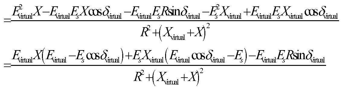
Q〜 ( virtual + ^ ^virtual ) ( virtual ~ ^s)
+(U )2 (9) 由式(9)可知, 可以通过虚拟发电机电压的控制实现逆变器注入系统的无功功率的 控制。
第二个问题的解决方案就是利用下垂特性求得虚拟发电机的电压指令值后, 再反推 接入点 B点的参考电压, 然后控制变流器的输出电压跟踪该参考电压, 从而间接地实现 对虚拟发电机端电压的控制, 即:
Λ = /*- (尸 W-尸 *) (10)
^virtual (ή = ^virtual -mQ(Q(t)-Q*) (
27i/vlrtual (t)积分得 rtual, 再和 Evlrtuai ω合成虚拟发电机的瞬时值 evlrtual, 贝 ijDG电压 瞬时指令值为:
_ di0
¾G-ref ― ^virtual ― virtual ~~~
dt (12)
根据式 (8)
EOG -V0 ^G(s)V0_Ki-Z(s)I{
= G(s)(EM -sLmAmXI0)-Z(s)l0 = G{s)E^d -(Gis^sL^^ +Z(s))l0
(13)
=l, 则

相当于在虚拟发电机 C点和 B点之间加入了 s£vlrtual+ Z( 的虚拟阻抗,只要 £vlrtual取得相 对较大, 就可确保等效系统图 4线路 AC的感性, 实现逆变器 Ρ, β的解耦。
式 (12) 需对电流进行微分, 可能放大高频噪声, 实际使用过程中需要对电流进行 滤波, 本发明仿真示例采用一阶低通滤波 s + 。

式 (15) 中 Evlrtual分别是逆变器无功功率, 虚拟发电机的端电压。 当逆变器输出 最大无功 max, 则 EDe达到最低值 EDemm; 当逆变器输出最小无功 mm, 则 EDe达到最大值
EDG 种情况下的电压变化要求, 本发明取为:
X virtual (16)
 E DGmax 本发明的技术效果可以参照以下的仿真示例来说明:
仿真系统如图 5所示, 该系统由两个逆变器组成, 电压为 380V, 线路 1和线路 2 的长度皆为 200m, 线路参数为 R=0.64 /km, X=0.101Q/km, 负荷由电阻和电抗串联而 成, 参数如表 1所示, 所有电抗参数为工频值。
表 1 微网负荷参数
Z LD1 Z LD2 Z LD3 Z LD4
负荷
-LD1 X LD1 LD2 X LD2 LD3 X LD3 LD4 X LD4
500 3.14 200 3.14 30 12.56 30 12.56 控制参数如表 2 所示, 逆变器 1、 2 的额定有功、 额定无功分别为 f = =0,
Ql =Q2 f =0,负荷 ZLD4是在 i=0.4s时投入的。对传统控制方法和本文所提方法进行了仿真, 开关频率c为 6000Hz。 其中, Λ Ρι、 βι β2 DG1 DG2 yi、 /2分别代表逆变器 1和 逆变器 2的有功、 无功、 输出电压及频率。
o
表 2 控制器参数
V&cN fc L/mH ClwF R Κ ρ Kyi KQ? ω0
800 6000 0.6 1500 0.01
逆变器 1 逆变器 2
mi? mio m2P m20
m
(1) 传统控制方法的仿真结果 o
由图 6—图 8可知, 仿真启动经过一段时间后微网达到稳定, 此时 Λ: 2=2:l; 0.4s 时 ZLD4投入, 经过一段时间后, 微网再次达到稳定, 逆变器 1 2按比例共同承担新增负 荷, 此时仍然有 Λ: i¾=2:l。 这一点是显而易见的,O因为整个微网的频率是统一的, 艮卩:
o
/;=/2根据式 (5), 结合 = =0, 则!^^尸 -/尸 o:/^ m2P尸 2 即逆变器 1 2按照 下垂系数的反比承担负荷。
o
由 7可知, 在整个仿真过程中出现了严重后果: 逆变器 2发出无功, 逆变器 1吸收 无功, 二者的差值就是负荷的无功, 而且逆变器 1和逆变器 2的有功差别增加后, 这种 情况更加突出。 o 图 8分别是逆变器 1输出的电压波形, 在负荷变动的过程中, 电压变化较 o小。
(2) 本发明控制方法的仿真结果
图 9一图 11是采用虚拟电抗下垂控制的仿真波形, 微网同样保持了稳定。
图 9同样表明, 逆变器 1 2按 -/下垂斜率的反比承担负荷。
图 10表明 和 都为正值, 避免了一个发出无功, 一个吸收无功的情况。
图 11分别是逆变器 1的电压波形, 在负荷变动的过程中, 电压变化较小。
(3) 二者的比较
比较传统方法和本发明的仿真结果可知: 当线路为阻性时,传统下垂控制方法效果 较差, 会出现部分逆变器发出无功, 部分发电机吸收无功的严重后果; 采用本发明的控 制方法后, 实现了逆变器有功和无功的解耦, 上述问题不再出现。
Claims
1、 一种基于虚拟阻抗的逆变器并联运行方法, 其特征在于:
针对每台逆变器, 引入一虚拟发电机,虚拟发电机通过虚拟阻抗接入逆变器所在点, 虚拟阻抗可以根据需要设置; 将逆变器的控制等效成通过虚拟发电机对逆变器所在点状 态的控制;
对虚拟发电机使用下垂控制, 利用逆变器的有功和无功分别调节虚拟发电机的频率 以及电压幅值, 进而求得虚拟发电机的电压指令值;
在此基础上进一步求得逆变器的输出电压指令值, 控制逆变器输出电压跟踪该指令 值, 从而实现对虚拟发电机的电压的控制, 最终实现对有功和无功的解耦调节。
2、如权利要求 1所述的基于虚拟阻抗的逆变器并联运行方法, 其特征在于: 所述下 垂控制包括功率控制器和电压跟踪器, 所述功率控制器利用基于虚拟阻抗的下垂特性求 出逆变器输出电压的指令值, 实现对有功和无功的调节; 所述电压跟踪器控制逆变器的 输出电压, 使其跟踪指令值。
Applications Claiming Priority (2)
| Application Number | Priority Date | Filing Date | Title |
|---|---|---|---|
| CN201110047934.7A CN102157956B (zh) | 2011-03-01 | 2011-03-01 | 基于虚拟阻抗的逆变器并联运行方法 |
| CN201110047934.7 | 2011-03-01 |
Publications (1)
| Publication Number | Publication Date |
|---|---|
| WO2012116559A1 true WO2012116559A1 (zh) | 2012-09-07 |
Family
ID=44439206
Family Applications (1)
| Application Number | Title | Priority Date | Filing Date |
|---|---|---|---|
| PCT/CN2011/083128 Ceased WO2012116559A1 (zh) | 2011-03-01 | 2011-11-29 | 基于虚拟阻抗的逆变器并联运行方法 |
Country Status (2)
| Country | Link |
|---|---|
| CN (1) | CN102157956B (zh) |
| WO (1) | WO2012116559A1 (zh) |
Cited By (7)
| Publication number | Priority date | Publication date | Assignee | Title |
|---|---|---|---|---|
| CN104377697A (zh) * | 2014-11-27 | 2015-02-25 | 国家电网公司 | 模拟同步发电机动态特性的电压源换流站的控制方法 |
| FR3047850A1 (fr) * | 2016-02-16 | 2017-08-18 | Schneider Electric Ind Sas | Procede de controle d'un generateur virtuel |
| US10008854B2 (en) | 2015-02-19 | 2018-06-26 | Enphase Energy, Inc. | Method and apparatus for time-domain droop control with integrated phasor current control |
| EP3800777A1 (fr) | 2019-10-02 | 2021-04-07 | Schneider Electric Industries SAS | Modification des valeurs de paramètres de la loi de commande d'un générateur |
| CN116127704A (zh) * | 2022-11-30 | 2023-05-16 | 广东电网有限责任公司 | 考虑逆变器高精度功率输出的虚拟阻抗设计方法和系统 |
| CN116244967A (zh) * | 2023-03-30 | 2023-06-09 | 中南大学 | 基于耦合矩阵反馈的微电网广义同步控制框架设计方法 |
| CN119651804A (zh) * | 2024-12-05 | 2025-03-18 | 国网福建省电力有限公司 | 一种基于自适应虚拟阻抗的改进下垂控制方法及系统 |
Families Citing this family (33)
| Publication number | Priority date | Publication date | Assignee | Title |
|---|---|---|---|---|
| CN102157956B (zh) * | 2011-03-01 | 2014-04-16 | 国网电力科学研究院 | 基于虚拟阻抗的逆变器并联运行方法 |
| CN102510120B (zh) * | 2011-11-23 | 2014-02-26 | 中国科学院电工研究所 | 一种基于虚拟阻抗的微网逆变器电压电流双环下垂控制方法 |
| CN102623992A (zh) * | 2012-04-12 | 2012-08-01 | 山东大学 | 基于旋转坐标虚拟阻抗的孤岛微电网控制及优化方法 |
| CN102832839A (zh) * | 2012-09-19 | 2012-12-19 | 张笑天 | 一种电压型并联逆变器的控制方法 |
| CN103001247B (zh) * | 2012-11-13 | 2014-09-10 | 中国电力科学研究院 | 一种离网型微电网黑启动方法 |
| CN102983589B (zh) * | 2012-11-15 | 2014-10-22 | 中国电力科学研究院 | 一种基于混合储能的电网友好型分布式电源的控制方法 |
| CN103001223B (zh) * | 2012-11-16 | 2014-07-23 | 中国电力科学研究院 | 一种基于储能换流器控制的离网型微电网频率调节方法 |
| CN103151794B (zh) * | 2013-01-11 | 2015-04-08 | 燕山大学 | 微电网分布式电源逆变器的自适应功率解耦方法 |
| CN103280843B (zh) * | 2013-04-27 | 2015-04-01 | 国家电网公司 | 一种不等容逆变器并联运行负荷分担的控制方法 |
| CN103701351B (zh) * | 2013-12-16 | 2016-02-24 | 西安交通大学 | 并联逆变器的自适应无功功率控制方法 |
| CN103779875B (zh) * | 2014-01-21 | 2016-05-04 | 燕山大学 | 分布式系统并网传输线等效阻抗比率获取方法 |
| CN104079198A (zh) * | 2014-07-15 | 2014-10-01 | 上海电力学院 | 基于可控虚拟阻抗的不同容量逆变器并联控制方法 |
| CN104092242B (zh) * | 2014-07-15 | 2016-03-30 | 上海电力学院 | 一种基于可控虚拟阻抗的逆变器并联控制方法 |
| CN104617597B (zh) * | 2015-02-12 | 2017-01-04 | 云南电网有限责任公司电网规划研究中心 | 减小逆变器并联运行时电压频率静差的控制方法 |
| CN105634004B (zh) * | 2015-05-26 | 2018-08-17 | 华北电力大学 | 一种基于虚拟同步发电机控制的电压源换流器等值方法 |
| CN106329525B (zh) * | 2015-06-18 | 2018-09-28 | 台达电子工业股份有限公司 | 环流与电流振荡的抑制方法及并联式逆变驱动系统 |
| CN105226727B (zh) * | 2015-10-12 | 2017-12-01 | 合肥工业大学 | 基于虚拟电容的微网逆变器并联功率均分控制方法 |
| CN105576708B (zh) * | 2015-12-31 | 2018-02-23 | 国网上海市电力公司 | 一种微电网中逆变器并联运行时无功均衡分配控制方法 |
| CN105826950B (zh) * | 2016-05-18 | 2019-06-28 | 江苏大学 | 一种逆变器虚拟阻抗的矢量图分析方法 |
| CN106099935B (zh) * | 2016-06-16 | 2018-08-03 | 许继集团有限公司 | 母线电压偏差自动补偿的下垂控制方法与下垂控制器 |
| CN106451497B (zh) * | 2016-11-25 | 2018-10-09 | 重庆大学 | 一种孤岛模式下逆变器并联系统的谐振抑制方法 |
| CN106712088B (zh) * | 2017-01-17 | 2020-01-07 | 燕山大学 | 基于虚拟阻抗与虚拟电源的低压微电网逆变器控制体系 |
| CN107241028B (zh) * | 2017-06-14 | 2019-04-05 | 山西大学 | 一种基于电量虚拟化的逆变器并联下垂控制方法 |
| CN108448919B (zh) * | 2017-12-21 | 2020-04-21 | 南京工程学院 | 一种基于虚拟电抗的模块化多电平变换器环流抑制方法 |
| CN108123466B (zh) * | 2017-12-29 | 2021-01-15 | 南京理工大学 | 一种基于功率串联解耦的储能变流器并联均流控制方法 |
| CN108418254B (zh) * | 2018-03-27 | 2020-06-23 | 华北电力大学 | 一种虚拟同步机并联系统稳定控制方法 |
| CN111585302B (zh) * | 2020-04-27 | 2021-09-14 | 武汉天富海科技发展有限公司 | 基于改进下垂控制的舰用逆变器并网优化方法 |
| EP3993215A1 (de) | 2020-10-29 | 2022-05-04 | Wobben Properties GmbH | Dynamische frt-bänder für windenergieanlagen |
| CN113178893B (zh) * | 2021-05-26 | 2022-11-29 | 华北电力大学 | 基于虚拟同步发电机控制的逆变器并联软启动方法及系统 |
| CN113394986A (zh) * | 2021-06-21 | 2021-09-14 | 湖南工业大学 | 一种高频链矩阵变换器功率均分方法 |
| CN113726001B (zh) * | 2021-07-23 | 2024-11-22 | 华为数字能源技术有限公司 | 一种系统控制方法及相关装置 |
| CN119010198B (zh) * | 2024-10-25 | 2025-04-18 | 国网浙江省电力有限公司温州供电公司 | 一种构网型逆变器并联运行控制方法及系统 |
| CN120934099B (zh) * | 2025-10-14 | 2026-01-06 | 国网安徽省电力有限公司经济技术研究院 | 基于光伏逆变器剩余容量的电压控制方法及系统 |
Citations (1)
| Publication number | Priority date | Publication date | Assignee | Title |
|---|---|---|---|---|
| CN102157956A (zh) * | 2011-03-01 | 2011-08-17 | 国网电力科学研究院 | 基于虚拟阻抗的逆变器并联运行方法 |
Family Cites Families (2)
| Publication number | Priority date | Publication date | Assignee | Title |
|---|---|---|---|---|
| JP4814740B2 (ja) * | 2006-09-22 | 2011-11-16 | サンデン株式会社 | インバータ装置 |
| JP5153241B2 (ja) * | 2007-07-18 | 2013-02-27 | 三菱電機株式会社 | 整流回路 |
-
2011
- 2011-03-01 CN CN201110047934.7A patent/CN102157956B/zh active Active
- 2011-11-29 WO PCT/CN2011/083128 patent/WO2012116559A1/zh not_active Ceased
Patent Citations (1)
| Publication number | Priority date | Publication date | Assignee | Title |
|---|---|---|---|---|
| CN102157956A (zh) * | 2011-03-01 | 2011-08-17 | 国网电力科学研究院 | 基于虚拟阻抗的逆变器并联运行方法 |
Non-Patent Citations (3)
| Title |
|---|
| JOSEP M. GUERRERO ET AL.: "Wireless-Control Strategy For Parallel Operation Of Distributed-Generation Inverters.", IEEE TRANSACTIONS ON INDUSTRIAL ELECTRONICS., vol. 53, no. 5, October 2006 (2006-10-01), pages 1461 - 1470 * |
| LI, MINYUAN ET AL.: "A Synthesis Wireless Control Strategy for Parallel Operation of 400Hz Inverters.", JOURNAL OF XI AN UNIVERSITY OF TECHNOLOGY (2010)., vol. 26, no. 2, 30 June 2010 (2010-06-30), pages 142 - 147 * |
| ZHAO, JUNFENG ET AL.: "A Research On Simulation Of Parallel Operation Of Single-Phase Inverters.", JOURNAL OF SHAANXI UNIVERSITY OF SCIENCE & TECHNOLOGY (NATURAL SCIENCE EDITION)., vol. 28, no. 6, 25 December 2010 (2010-12-25), pages 90 - 94 * |
Cited By (13)
| Publication number | Priority date | Publication date | Assignee | Title |
|---|---|---|---|---|
| CN104377697A (zh) * | 2014-11-27 | 2015-02-25 | 国家电网公司 | 模拟同步发电机动态特性的电压源换流站的控制方法 |
| US11355936B2 (en) | 2015-02-19 | 2022-06-07 | Enphase Energy, Inc. | Method and apparatus for time-domain droop control with integrated phasor current control |
| US10008854B2 (en) | 2015-02-19 | 2018-06-26 | Enphase Energy, Inc. | Method and apparatus for time-domain droop control with integrated phasor current control |
| US10951037B2 (en) | 2015-02-19 | 2021-03-16 | Enphase Energy, Inc. | Method and apparatus for time-domain droop control with integrated phasor current control |
| FR3047850A1 (fr) * | 2016-02-16 | 2017-08-18 | Schneider Electric Ind Sas | Procede de controle d'un generateur virtuel |
| EP3208907A1 (fr) * | 2016-02-16 | 2017-08-23 | Schneider Electric Industries SAS | Procede de controle d'un generateur virtuel |
| US10452091B2 (en) | 2016-02-16 | 2019-10-22 | Schneider Electric Industries Sas | Control method of a virtual generator |
| EP3800777A1 (fr) | 2019-10-02 | 2021-04-07 | Schneider Electric Industries SAS | Modification des valeurs de paramètres de la loi de commande d'un générateur |
| FR3101739A1 (fr) | 2019-10-02 | 2021-04-09 | Schneider Electric Industries Sas | Modification des valeurs de paramètres de la loi de commande d’un générateur |
| US12609642B2 (en) | 2019-10-02 | 2026-04-21 | Schneider Electric Industries Sas | Adjustment of parameter values of a control rule of a generator |
| CN116127704A (zh) * | 2022-11-30 | 2023-05-16 | 广东电网有限责任公司 | 考虑逆变器高精度功率输出的虚拟阻抗设计方法和系统 |
| CN116244967A (zh) * | 2023-03-30 | 2023-06-09 | 中南大学 | 基于耦合矩阵反馈的微电网广义同步控制框架设计方法 |
| CN119651804A (zh) * | 2024-12-05 | 2025-03-18 | 国网福建省电力有限公司 | 一种基于自适应虚拟阻抗的改进下垂控制方法及系统 |
Also Published As
| Publication number | Publication date |
|---|---|
| CN102157956A (zh) | 2011-08-17 |
| CN102157956B (zh) | 2014-04-16 |
Similar Documents
| Publication | Publication Date | Title |
|---|---|---|
| CN102157956B (zh) | 基于虚拟阻抗的逆变器并联运行方法 | |
| Gao et al. | Seamless switching method between grid-following and grid-forming control for renewable energy conversion systems | |
| CN105811421B (zh) | 一种基于改进型下垂控制的微电网辅助主从控制方法 | |
| CN102510120B (zh) | 一种基于虚拟阻抗的微网逆变器电压电流双环下垂控制方法 | |
| CN103956769B (zh) | 一种基于模糊pi算法的微电网并网逆变器的控制方法 | |
| Huang et al. | Comprehensive coordinated frequency control of symmetrical CLLC-DC transformer in hybrid AC/DC microgrids | |
| Zhang et al. | Principle and robust impedance-based design of grid-tied inverter with LLCL-filter under wide variation of grid-reactance | |
| CN103606954A (zh) | 一种新型光伏并网发电控制方法 | |
| CN109449999A (zh) | 基于自适应虚拟阻抗的低压微电网分布式控制方法及系统 | |
| CN105305410A (zh) | 一种直流配电系统储能装置自适应虚拟阻抗下垂控制方法 | |
| CN102437572A (zh) | 一种潮流控制系统 | |
| CN107482682A (zh) | 一种离网模式下有源滤波器与分布式电源协同控制方法 | |
| CN116505534A (zh) | 一种直接式ac/ac型混合配电变压器的建模方法 | |
| CN110137971B (zh) | 一种三相交流电力弹簧的电压平稳控制方法 | |
| Choi et al. | Selective frequency synchronization technique for fast grid connection of islanded microgrid using prediction method | |
| Tarraso et al. | Selective harmonic compensation in SPC grid-forming converters for improving power quality in weak grid | |
| CN111711198A (zh) | 一种基于fms的配电网馈线互联控制方法 | |
| Monica et al. | Load sharing control of parallel operated single phase inverters | |
| CN104092249B (zh) | 一种适用于低压微网的改进型下垂控制方法 | |
| CN106953361B (zh) | 交流微电网运行控制方法及装置 | |
| CN106253305A (zh) | 一种针对分布式电源的全分散式孤岛无功控制方法 | |
| CN106130387B (zh) | 含lcl滤波器的逆变器并网控制方法 | |
| CN101478164A (zh) | 独立与并网双模式运行逆变器的控制方法 | |
| CN105680714A (zh) | 逆变器输出电压的控制方法及装置 | |
| CN104638634A (zh) | 主从模式下基于带通滤波器的直流微电网振荡抑制方法 |
Legal Events
| Date | Code | Title | Description |
|---|---|---|---|
| 121 | Ep: the epo has been informed by wipo that ep was designated in this application |
Ref document number: 11859980 Country of ref document: EP Kind code of ref document: A1 |
|
| NENP | Non-entry into the national phase |
Ref country code: DE |
|
| 122 | Ep: pct application non-entry in european phase |
Ref document number: 11859980 Country of ref document: EP Kind code of ref document: A1 |