WO2012117440A1 - 熱交換器及びこの熱交換器を備えた冷蔵庫、空気調和機 - Google Patents
熱交換器及びこの熱交換器を備えた冷蔵庫、空気調和機 Download PDFInfo
- Publication number
- WO2012117440A1 WO2012117440A1 PCT/JP2011/001170 JP2011001170W WO2012117440A1 WO 2012117440 A1 WO2012117440 A1 WO 2012117440A1 JP 2011001170 W JP2011001170 W JP 2011001170W WO 2012117440 A1 WO2012117440 A1 WO 2012117440A1
- Authority
- WO
- WIPO (PCT)
- Prior art keywords
- heat exchanger
- fin
- thickness
- heat transfer
- radius
- Prior art date
- Legal status (The legal status is an assumption and is not a legal conclusion. Google has not performed a legal analysis and makes no representation as to the accuracy of the status listed.)
- Ceased
Links
Images


Classifications
-
- F—MECHANICAL ENGINEERING; LIGHTING; HEATING; WEAPONS; BLASTING
- F28—HEAT EXCHANGE IN GENERAL
- F28F—DETAILS OF HEAT-EXCHANGE AND HEAT-TRANSFER APPARATUS, OF GENERAL APPLICATION
- F28F1/00—Tubular elements; Assemblies of tubular elements
- F28F1/10—Tubular elements and assemblies thereof with means for increasing heat-transfer area, e.g. with fins, with projections, with recesses
- F28F1/12—Tubular elements and assemblies thereof with means for increasing heat-transfer area, e.g. with fins, with projections, with recesses the means being only outside the tubular element
- F28F1/24—Tubular elements and assemblies thereof with means for increasing heat-transfer area, e.g. with fins, with projections, with recesses the means being only outside the tubular element and extending transversely
- F28F1/32—Tubular elements and assemblies thereof with means for increasing heat-transfer area, e.g. with fins, with projections, with recesses the means being only outside the tubular element and extending transversely the means having portions engaging further tubular elements
-
- F—MECHANICAL ENGINEERING; LIGHTING; HEATING; WEAPONS; BLASTING
- F28—HEAT EXCHANGE IN GENERAL
- F28D—HEAT-EXCHANGE APPARATUS, NOT PROVIDED FOR IN ANOTHER SUBCLASS, IN WHICH THE HEAT-EXCHANGE MEDIA DO NOT COME INTO DIRECT CONTACT
- F28D7/00—Heat-exchange apparatus having stationary tubular conduit assemblies for both heat-exchange media, the media being in contact with different sides of a conduit wall
- F28D7/06—Heat-exchange apparatus having stationary tubular conduit assemblies for both heat-exchange media, the media being in contact with different sides of a conduit wall the conduits having a single U-bend
-
- F—MECHANICAL ENGINEERING; LIGHTING; HEATING; WEAPONS; BLASTING
- F28—HEAT EXCHANGE IN GENERAL
- F28F—DETAILS OF HEAT-EXCHANGE AND HEAT-TRANSFER APPARATUS, OF GENERAL APPLICATION
- F28F1/00—Tubular elements; Assemblies of tubular elements
- F28F1/10—Tubular elements and assemblies thereof with means for increasing heat-transfer area, e.g. with fins, with projections, with recesses
- F28F1/42—Tubular elements and assemblies thereof with means for increasing heat-transfer area, e.g. with fins, with projections, with recesses the means being both outside and inside the tubular element
-
- B—PERFORMING OPERATIONS; TRANSPORTING
- B21—MECHANICAL METAL-WORKING WITHOUT ESSENTIALLY REMOVING MATERIAL; PUNCHING METAL
- B21D—WORKING OR PROCESSING OF SHEET METAL OR METAL TUBES, RODS OR PROFILES WITHOUT ESSENTIALLY REMOVING MATERIAL; PUNCHING METAL
- B21D53/00—Making other particular articles
- B21D53/02—Making other particular articles heat exchangers or parts thereof, e.g. radiators, condensers fins, headers
- B21D53/08—Making other particular articles heat exchangers or parts thereof, e.g. radiators, condensers fins, headers of both metal tubes and sheet metal
-
- F—MECHANICAL ENGINEERING; LIGHTING; HEATING; WEAPONS; BLASTING
- F28—HEAT EXCHANGE IN GENERAL
- F28D—HEAT-EXCHANGE APPARATUS, NOT PROVIDED FOR IN ANOTHER SUBCLASS, IN WHICH THE HEAT-EXCHANGE MEDIA DO NOT COME INTO DIRECT CONTACT
- F28D21/00—Heat-exchange apparatus not covered by any of the groups F28D1/00 - F28D20/00
- F28D2021/0019—Other heat exchangers for particular applications; Heat exchange systems not otherwise provided for
- F28D2021/0068—Other heat exchangers for particular applications; Heat exchange systems not otherwise provided for for refrigerant cycles
-
- F—MECHANICAL ENGINEERING; LIGHTING; HEATING; WEAPONS; BLASTING
- F28—HEAT EXCHANGE IN GENERAL
- F28F—DETAILS OF HEAT-EXCHANGE AND HEAT-TRANSFER APPARATUS, OF GENERAL APPLICATION
- F28F1/00—Tubular elements; Assemblies of tubular elements
- F28F1/10—Tubular elements and assemblies thereof with means for increasing heat-transfer area, e.g. with fins, with projections, with recesses
- F28F1/42—Tubular elements and assemblies thereof with means for increasing heat-transfer area, e.g. with fins, with projections, with recesses the means being both outside and inside the tubular element
- F28F2001/428—Particular methods for manufacturing outside or inside fins
-
- F—MECHANICAL ENGINEERING; LIGHTING; HEATING; WEAPONS; BLASTING
- F28—HEAT EXCHANGE IN GENERAL
- F28F—DETAILS OF HEAT-EXCHANGE AND HEAT-TRANSFER APPARATUS, OF GENERAL APPLICATION
- F28F2275/00—Fastening; Joining
- F28F2275/12—Fastening; Joining by methods involving deformation of the elements
- F28F2275/125—Fastening; Joining by methods involving deformation of the elements by bringing elements together and expanding
Definitions
- the present invention relates to a heat exchanger used in, for example, a refrigerator and an air conditioner, and a refrigerator and an air conditioner equipped with the heat exchanger.
- a heat exchanger used in a conventional refrigerator or air conditioner is known as a fin tube heat exchanger.
- This heat exchanger is inserted at right angles to plate fins that are arranged at regular intervals and through which gas (air) flows, and the plate fins (hereinafter simply referred to as fins), in which refrigerant flows. It consists of a heat pipe.
- Factors that affect the heat transfer performance of such a finned tube heat exchanger include the refrigerant side heat transfer coefficient between the refrigerant and the heat transfer tube, the contact heat transfer coefficient between the heat transfer tube and the fin, and air The air side heat transfer coefficient between the fin and the fin is known.
- the in-pipe performance is promoted by the inner surface groove of the heat transfer tube, which provides an area expansion of the heat transfer tube and an effect of stirring the refrigerant.
- the slit group by cutting and raising to a fin is provided between the adjacent heat exchanger tubes. This slit group is provided so that the side end portion of the slit is opposed to the wind direction, and heat transfer is promoted by thinning the velocity boundary layer and the temperature boundary layer of the air flow at the side end portion.
- the crack heat exchange capacity is said to increase.
- the contact heat transfer coefficient between the heat transfer tube and the fin is affected by the contact state between the heat transfer tube and the fin.
- the fin collar 2 into which the heat transfer tube 10 of the fin 1 is inserted has three or more bends R.
- a technique has been proposed in which each of the bends R is smoothly connected, and the shape of the fin collar-2 is generally convex toward the heat transfer tube 5 so that there is no straight portion (for example, a patent) Reference 1).
- the fin collar 2 is provided with three or more bends R, each of the bends R is smoothly connected, and the shape of the fin collar 2 is made convex toward the heat transfer tube 5 as a whole. Since there is no straight part, when inserting the heat transfer tube 5 into the fin collar 2 due to defects in the bending R molding process, the insertion force increases, resulting in an increase in mass production cost and the desired heat transfer performance cannot be obtained. There was a problem.
- a heat exchanger capable of increasing the heat exchange capacity by reducing the contact thermal resistance between the heat transfer tube and the fin collar of the fin, and the heat It aims at providing the refrigerator provided with the exchanger, and the air conditioner.
- the present invention includes a plurality of heat transfer tubes arranged in parallel and a plurality of plate fins provided orthogonal to the heat transfer tubes, and a fin collar into which the heat transfer tubes of the first plate fins are inserted.
- a fin tube type heat exchanger formed by contacting the heat transfer tubes,
- the fin collar is provided with a bent portion at a flared portion and a base portion of the fin collar, and a flat intermediate portion is formed between the two bent portions, and the thickness of the flared portion is smaller than the thickness of the root portion.
- the radius of the bent portion of the refracted portion is formed larger than the radius of the bent portion of the root portion, and the ratio of the radius of the bent portion of the flared portion and the thickness is the radius of the bent portion of the root portion. It is configured to be at least half of the ratio to the thickness.
- a refrigerator or an air conditioner according to the present invention includes the above heat exchanger.
- the contact heat resistance of a heat exchanger tube and the fin collar of a fin reduces, and the heat exchanger which can increase heat exchange capability, a refrigerator provided with this heat exchanger, and an air conditioner are obtained. Can do.
- FIG. 3 is an explanatory diagram of a method for manufacturing the heat exchanger according to Embodiment 1.
- FIG. It is a diagram which shows the relationship between the ratio of the radius and thickness of the bending part of the fin collar of the heat exchanger which concern on Embodiment 1, and a heat exchange rate.
- FIG. It is a diagram which shows the relationship between the ratio of the radius and thickness of the bending part of the fin collar of the heat exchanger which concern on Embodiment 1, and a heat exchange rate.
- It is an enlarged view of the principal part of the heat exchanger which concerns on Embodiment 2 of this invention, and sectional drawing of a heat exchanger tube.
- FIG. 1 is an enlarged cross-sectional view of a main part after pipe expansion of a heat exchanger according to Embodiment 1 of the present invention.
- 1 is a fin made of a heat-resistant metal plate such as a copper alloy or an aluminum alloy (the same applies to other embodiments), and is orthogonal to the fin 1 and is copper or copper alloy or aluminum or aluminum alloy.
- a heat transfer tube 10 made of a metal material such as the same (also in other embodiments) is provided.
- each heat transfer tube 10 is bent into a hairpin shape at a predetermined bending pitch at the center in the longitudinal direction, and a plurality of hairpin tubes are manufactured.
- these hairpin tubes are inserted between the fin collars 2 of a plurality of fins 1 arranged in parallel with each other at a predetermined interval, and then expanded into the hairpin tube as shown in FIG. 2 (a).
- Each of the fins 1 and the hairpin is expanded by a mechanical tube expansion method in which the ball 15 is pushed by the rod 16 or by a hydraulic tube expansion method in which the tube expansion ball 15 is pushed into the hairpin tube by the fluid 17 as shown in FIG.
- the tube that is, the heat transfer tube 10 is joined.
- a fin tube type heat exchanger is manufactured.
- the heat exchanger manufactured as described above includes a plurality of heat transfer tubes 10 arranged in parallel and a plurality of fins 1 orthogonal to the heat transfer tubes 10, and the heat transfer tubes 10 of the fins 1 are inserted therethrough.
- the heat transfer tube 10 is brought into contact with the fin collar 2.
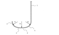
- the shape of the fin collar 2 is such that arcuate bent portions with radii R1 and R2 are provided at the flaring portion 3 and the root portion 4 so that the thickness Tw1 of the flaring portion 3 is thinner than the thickness Tw2 of the root portion 4.
- the ratio (Tw1 / R1) between the radius R1 of the bent portion 3 and the thickness Tw1 is equal to or more than half of the ratio (Tw2 / R2) between the radius R2 of the bent portion of the root portion 4 and the thickness Tw2. ing.
- An intermediate portion 5 having a flat outer surface is provided between the refracted portion 3 and the bent portion of the root portion 4, and is formed in a substantially J shape as a whole.
- the radius R1 of the bent portion of the refracted portion 3 of the fin collar 2 is formed larger than the radius R2 of the bent portion of the root portion 4, the root portion of the fin collar 2 of the front fin 1 after the heat transfer tube 10 is expanded. 4, the contact area between the rear fin 1 and the flared portion 3 of the fin collar 2 is increased, the contact thermal resistance is decreased, and the heat exchange capacity is increased.
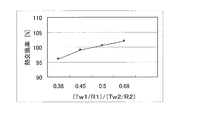
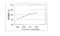
- 3 and 4 are graphs showing the relationship between the ratio between the radii R1 and R2 of the bent portion of the fin collar 2 and the bent portion 4 and the thicknesses Tw1 and Tw2, and the heat exchange rate.
- the radius R1 of the bent portion of the refracted portion 3 of the fin collar 2 is closely related to the thickness Tw1 of the refracted portion 3.
- Tw1 must also be thickened.
- the ratio (Tw1 / R1) between the radius R1 and the thickness Tw1 of the bent portion of the refracted portion 3 of the fin collar 2 is the ratio (Tw2 / R2) of the radius R2 and the thickness Tw2 of the bent portion of the root portion 4. If it is less than half, the contact surface pressure between the base portion 4 of the fin collar 2 of the front fin 1 and the refracted portion 3 of the fin collar 2 of the rear fin 1 is lowered, so The contact surface pressure between the part 5 and the heat transfer tube 10 decreases, the contact thermal resistance increases, and the heat exchange capacity decreases.
- the ratio (Tw1 / R1) between the radius R1 of the bent portion of the refracted portion 3 of the fin collar 2 and the thickness Tw1 (Tw1 / R1) is the ratio between the radius R2 of the bent portion of the root portion 4 and the thickness Tw2 (Tw2 / R2).
- FIG. 5 is an enlarged cross-sectional view of a main part of a heat exchanger according to Embodiment 2 of the present invention, and a cross-sectional view of a heat transfer tube.
- reference numeral 1 denotes a fin made of a heat-resistant metal plate such as a copper alloy or an aluminum alloy.
- the fin is made of a metal material such as copper or copper alloy or aluminum or aluminum alloy perpendicular to the fin 1 and has an axial direction on the inner peripheral surface.
- a heat transfer tube 10 provided with a plurality of inner surface protrusions 11 is provided.
- a bent portion is provided at the flared portion 3 and the root portion 4 of the fin collar 2 of the fin 1, and the ratio (Tw1 /) between the radius R1 and the thickness Tw1 of the bent portion of the flared portion 3.
- R1 is formed to be at least half of the ratio (Tw2 / R2) of the radius R2 and thickness Tw2 of the bent portion of the root portion 4, and the circumference of the heat transfer tube 10 having the outer diameter D
- Ratio with the thickness Tw2 of the base part 4 of the fin collar 2 ((Tw1 + Tw2) / 2)) / Tw2 is multiplied by a relational expression (3.14 ⁇ D / N) ⁇ ((Tw1 + Tw2) / 2)) / Tw2 , 0.26 or more and 0.34 or less.
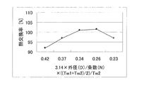
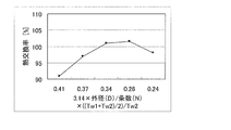
- 6 and 7 show the relational expression between the thickness Tw of the fin collar 2 of the fin 1, the outer diameter D of the heat transfer tube 10, and the number N of the inner surface protrusions 11 of the heat transfer tube 10, and the heat exchange rate (%).
- FIG. As shown in FIGS.
- the intermediate portion 5 of the fin collar 2 has a ratio (3.14 ⁇ D / N) between the circumferential length (3.14 ⁇ D) of the heat transfer tube 10 of the outer diameter D and the number N of the inner surface protrusions 11.
- Tw1 + Tw2 the thickness of the heat transfer tube 10 of the outer diameter D
- Tw2 the thickness of the root portion 4
- Tw2 is multiplied by the relational expression (3.14 ⁇ D / N) ⁇ ((Tw1 + Tw2 / 2) ))
- Tw2 is less than 0.26, the contact surface pressure between the intermediate portion 5 of the fin collar 2 and the heat transfer tube 10 decreases, the contact thermal resistance increases, and the heat exchange capacity decreases.
- the ratio (3.14 ⁇ D / N) of the peripheral length (3.14 ⁇ D) of the heat transfer tube 10 having the outer diameter D and the number N of the inner surface protrusions 11 is equal to the intermediate portion 5 of the fin collar 2.
- Tw2 exceeds 0.34, stress concentrates on the base part 4 of the fin collar 2, the contact surface pressure between the intermediate part 5 of the fin collar 2 and the heat transfer tube 10 decreases, and the contact thermal resistance increases. , Heat exchange capacity is reduced.
- the intermediate portion 5 of the fin collar 2 has a ratio (3.14 ⁇ D / N) between the circumferential length (3.14 ⁇ D) of the heat transfer tube 10 of the outer diameter D and the number N of the inner surface protrusions 11.
- the ratio of the average thickness (Tw1 + Tw2) / 2 to the thickness Tw2 of the base 4 ((Tw1 + Tw2) / 2)) / Tw2 is multiplied by the relational expression (3.14 ⁇ D / N) ⁇ ((Tw1 + Tw2) / 2)) / Tw2 is particularly preferably 0.27 or more and 0.31 or less.
- the ratio (3.14 ⁇ D / N) between the circumferential length (3.14 ⁇ D) of the heat transfer tube 10 having the outer diameter D and the number N of the inner surface protrusions 11 is obtained.
- X ((Tw1 + Tw2) / 2)) / Tw2 is set to be in a range of 0.26 to 0.34.
- the heat exchanger according to any one of Embodiments 1 and 2 is used for a refrigerator or an air conditioner. Thereby, the contact resistance of the fin 1 of the heat exchanger and the heat transfer tube 10 is reduced, and a highly efficient refrigerator or air conditioner having an increased heat exchange capability can be obtained.
- the refrigerator and the air conditioner according to the present invention include the HC single refrigerant or a mixed refrigerant containing HC as a working fluid, R32, R410A, R407C tetrafluoropropene, and an HFC system having a lower boiling point than the tetrafluoropropene.
- a refrigerant such as a non-azeotropic refrigerant or carbon dioxide composed of a refrigerant
- a heat exchanger according to the present invention is used for both or one of an evaporator and a condenser. is there.
- Example 2 examples of the present invention will be described in comparison with comparative examples that are out of the scope of the present invention.
- the radius R2 of the bent portion of the base portion 4 of the fin collar 2 of the fin 1 is 0.3 mm
- the thickness Tw2 is 0.1 mm
- the radius R1 of the bent portion of the flared portion 3 is 0.4 mm.
- a heat exchanger having a thickness Tw1 of 0.67 mm or 0.09 mm was manufactured (Example 1 and Example 2).
- the radius R2 of the bent portion of the root portion 4 of the fin collar 2 of the fin 1 is 0.3 mm
- the thickness Tw1 is 0.1 mm
- the radius R1 of the bent portion of the flared portion 3 is 0.4 mm.
- Heat exchangers having thicknesses Tw2 of 0.05 mm and 0.06 mm were manufactured (Comparative Example 1 and Comparative Example 2).
- Example 1 and Example 2 both have a higher heat exchange rate than the heat exchangers of Comparative Example 1 and Comparative Example 2, and the contact heat transfer rate is improved. It was.
- the radius R2 of the bent portion of the base portion 4 of the fin collar 2 of the fin 1 is 0.3 mm
- the thickness Tw2 is 0.1 mm
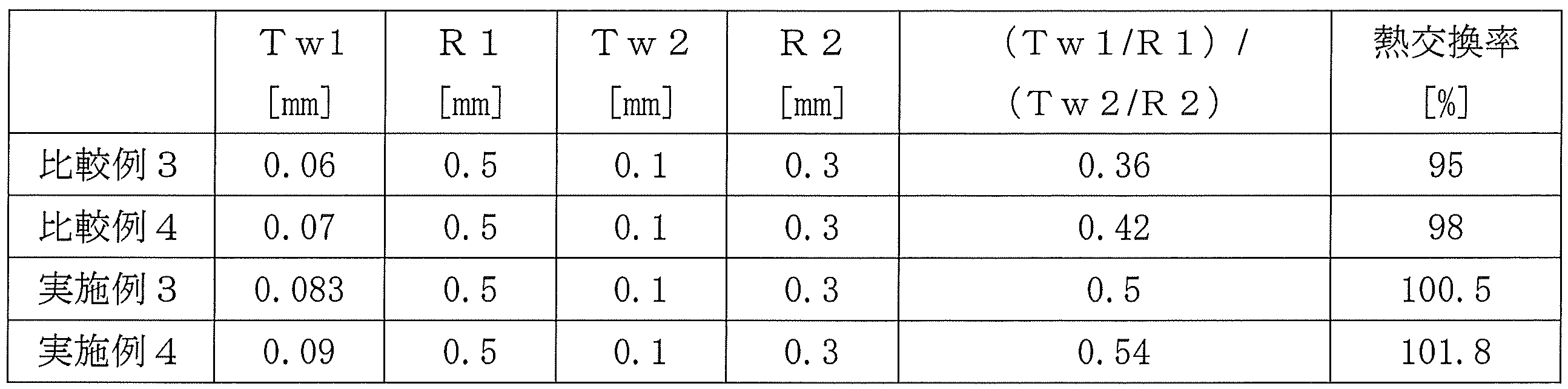
- the radius R1 of the bent portion of the flared portion 3 is A heat exchanger having a thickness of 0.5 mm and a thickness Tw1 of 0.083 mm and 0.09 mm was manufactured (Example 3 and Example 4).
- the radius R2 of the bent portion of the root portion 4 of the fin collar 2 of the fin 1 is 0.3 mm
- the thickness Tw2 is 0.1 mm
- the radius R1 of the bent portion of the flared portion 3 is 0.5 mm.
- Heat exchangers having a thickness Tw1 of 0.06 mm and 0.07 mm were manufactured (Comparative Example 3 and Comparative Example 4).
- Example 3 and Example 4 had higher heat exchange rates and improved contact heat transfer rates than Comparative Examples 3 and 4.
- the thickness Tw1 of the flared portion 3 of the fin collar 2 of the fin 1 is 0.07 mm
- the thickness Tw2 of the root portion 4 is 0.1 mm
- the outer diameter D of the heat transfer tube 10 is A heat exchanger having 7 mm and the number N of inner surface protrusions 11 of 55 and 72 was manufactured (Examples 5 and 6).
- the thickness Tw1 of the flare portion 3 of the fin collar 2 of the fin 1 is 0.07 mm
- the thickness Tw2 of the root portion 4 is 0.1 mm
- the outer diameter D of the heat transfer tube 10 is 7 mm
- Heat exchangers having 11 strips N of 45, 50 and 80 were manufactured (Comparative Example 5, Comparative Example 6 and Comparative Example 7).
- the heat exchangers of Examples 5 and 6 all have a higher heat exchange rate than the heat exchangers of Comparative Example 5, Comparative Example 6 and Comparative Example 7, and contact heat transfer. The rate was improving.
- the thickness Tw1 of the flared portion 3 of the fin collar 2 of the fin 1 is 0.09 mm
- the thickness Tw2 of the root portion 4 is 0.1 mm
- the outer diameter D of the heat transfer tube 10 is 7 mm.
- heat exchangers having the number N of the inner surface protrusions 11 of 60 and 80 were manufactured (Examples 7 and 8).
- the thickness Tw1 of the flared portion 3 of the fin collar 2 of the fin 1 is 0.09 mm
- the thickness Tw2 of the root portion 4 is 0.1 mm
- the outer radius D of the heat transfer tube 10 is 7 mm
- the inner surface protrusion Heat exchangers having 11 strips N of 50, 55, and 85 were manufactured (Comparative Example 8, Comparative Example 9, and Comparative Example 10).
- the heat exchangers of Examples 7 and 8 all have a higher heat exchange rate than the heat exchangers of Comparative Example 8, Comparative Example 9 and Comparative Example 10, and contact heat transfer. The rate was improving.
Landscapes
- Engineering & Computer Science (AREA)
- Physics & Mathematics (AREA)
- Thermal Sciences (AREA)
- Mechanical Engineering (AREA)
- General Engineering & Computer Science (AREA)
- Geometry (AREA)
- Heat-Exchange Devices With Radiators And Conduit Assemblies (AREA)
Abstract
Description
前記フィンカラーは、該フィンカラーのリフレア部と根元部に曲げ部が設けられてこれら両曲げ部の間に平坦な中間部が形成され、前記リフレア部の厚さは前記根元部の厚さより薄く形成され、前記リフレア部の曲げ部の半径は前記根元部の曲げ部の半径より大きく形成されて、前記リフレア部の曲げ部の半径と前記厚さとの比率が前記根元部の曲げ部の半径と前記厚さとの比率の2分の1以上になるように構成されたものである。
図1は本発明の実施の形態1に係る熱交換器の拡管後の要部の拡大断面図である。図1において、1は銅合金又はアルミニウム合金などの耐熱性金属板からなる(他の実施の形態においても同様である)フィンで、フィン1と直交して、銅若しくは銅合金又はアルミニウム若しくはアルミニウム合金などの金属材料からなる(他の実施の形態においても同様である)伝熱管10が設けられている。
熱交換器を製造するにあたっては、先ず、各伝熱管10をそれぞれ長手方向の中央部で所定の曲げピッチでヘアピン状に曲げ加工し、複数のヘアピン管を製作する。ついで、これらのヘアピン管を所定の間隔をおいて相互に平行に配置した複数枚のフィン1のフィンカラー2の間に挿通し、その後、図2(a)に示すように、ヘアピン管内に拡管玉15をロッド16により押し込む機械拡管方式、又は図2(b)に示すように、ヘアピン管内に拡管玉15を流体17により押し込む液圧拡管方式によりヘアピン管を拡管して、各フィン1とヘアピン管、すなわち伝熱管10とを接合する。こうしてフィンチューブ型熱交換器が製造される。
フィンカラー2の形状は、リフレア部3と根元部4に半径R1,R2の円弧状の曲げ部を設け、リフレア部3の厚さTw1が根元部4の厚さTw2より薄く形成され、リフレア部3の曲げ部の半径R1と厚さTw1との比率(Tw1/R1)が、根元部4の曲げ部の半径R2と厚さTw2との比率(Tw2/R2)の2分の1以上になっている。なお、リフレア部3と根元部4の曲げ部の間には外面側が平坦な中間部5が設けられ、全体としてほぼJ字状に形成されている。
フィンカラー2のリフレア部3の曲げ部の半径R1は、リフレア部3の厚さTw1と密接な関係があり、リフレア部3の曲げ部の半径R1を大きくする場合は、リフレア部3の厚さTw1も厚くしなければならない。フィンカラー2のリフレア部3の曲げ部の半径R1が大きくなっているときに、リフレア部3の厚さTw1が薄くなるとリフレア部3に応力が集中し、中間部5と伝熱管10との接触面圧が低下して接触熱抵抗が増加し、熱交換能力が低下する。
図5は本発明の実施の形態2に係る熱交換器の要部の拡大断面図、及び伝熱管の断面図である。なお、実施の形態1と同じ部分には、これと同じ符号が付してある。
図において、1は銅合金又はアルミニウム合金などの耐熱性金属板からなるフィンで、フィン1と直交して、銅若しくは銅合金又はアルミニウム若しくはアルミニウム合金などの金属材料からなり、内周面の軸方向に複数の内面突起11が設けられた伝熱管10が設けられている。
図6、図7は、フィン1のフィンカラー2の厚さTw、伝熱管10の外径D、及び伝熱管10の内面突起11の条数Nとの関係式と、熱交換率(%)との関係を示す線図である。
図6、図7に示すように、熱交換器の熱交換能力を維持するためには、外径Dの伝熱管10の円周長さ(3.14×D)と内面突起11の条数Nとの比率(3.14×D/N)に、フィンカラー2の中間部5平均厚さ(Tw1+Tw2)/2と、フィンカラー2の根元部4との厚さTw2との比率((Tw2+Tw1)/2))/Tw2を乗じた関係式(3.14×D/N)×((Tw1+Tw2)/2))/Tw2が、0.26以上0.34以下であることが必要である。
これにより、フィン1と伝熱管10との接触熱抵抗が低減し、熱交換能力が増大する。
本実施の形態は、冷蔵庫又は空気調和機に実施の形態1又は2のいずれかに係る熱交換器を用いたものである。
これにより、熱交換器のフィン1と伝熱管10との接触抵抗が低減し、熱交換能力が増大した高効率の冷蔵庫又は空気調和機を得ることができる。
次に、本発明の実施例について、本発明の範囲から外れる比較例と比較して説明する。
表1に示すように、フィン1のフィンカラー2の根元部4の曲げ部の半径R2が0.3mm、厚さTw2が0.1mmで、リフレア部3の曲げ部の半径R1が0.4mm、厚さTw1が0.67mm又は0.09mmである熱交換器を製作した(実施例1及び実施例2)。
また、比較例として、フィン1のフィンカラー2の根元部4の曲げ部の半径R2が0.3mm、厚さTw1が0.1mmで、リフレア部3の曲げ部の半径R1が0.4mm、厚さTw2が0.05mm及び0.06mmの熱交換器を製作した(比較例1及び比較例2)。

また、比較例として、フィン1のフィンカラー2の根元部4の曲げ部の半径R2が0.3mm、厚さTw2が0.1mmで、リフレア部3の曲げ部の半径R1が0.5mm、厚さTw1が0.06mm及び0.07mmの熱交換器を製作した(比較例3及び比較例4)。
また、比較例として、フィン1のフィンカラー2のリフレア部3の厚さTw1が0.07mm、根元部4の厚さTw2が0.1mmで、伝熱管10の外径Dが7mm、内面突起11の条数Nが45、50及び80の熱交換器を製作した(比較例5、比較例6及び比較例7)。

また、比較例として、フィン1のフィンカラー2のリフレア部3の厚さTw1が0.09mm、根元部4の厚さTw2が0.1mmで、伝熱管10の外半径Dが7mm、内面突起11の条数Nが50、55及び85の熱交換器を製作した(比較例8、比較例9及び比較例10)。

Claims (4)
- 平行に配置した複数の伝熱管と、該伝熱管に対して直交して設けられた複数の板状フィンとを備え、前記板状フィンの前記伝熱管が挿通されるフィンカラーに前記伝熱管を接触させてなるフィンチューブ型の熱交換器であって、
前記フィンカラーは、該フィンカラーのリフレア部と根元部に曲げ部が設けられてこれら両曲げ部の間に平坦な中間部が形成され、前記リフレア部の厚さは前記根元部の厚さより薄く形成され、前記リフレア部の曲げ部の半径は前記根元部の曲げ部の半径より大きく形成されて、前記リフレア部の曲げ部の半径と前記厚さとの比率が前記根元部の曲げ部の半径と前記厚さとの比率の2分の1以上になるように構成されていることを特徴とする熱交換器。 - 前記伝熱管を、その円周長さと内面突起の合計条数との比に、前記フィンカラーの中間部の平均厚さと該フィンカラーの根元部の厚さとの比を掛けた関係式の値が0.26以上
0.34以下の範囲になるように形成したことを特徴とする請求項1記載の熱交換器。 - 前記請求項1又は2に記載の熱交換器を備えたことを特徴とする冷蔵庫。
- 前記請求項1又は2に記載の熱交換器を備えたことを特徴とする空気調和機。
Priority Applications (7)
| Application Number | Priority Date | Filing Date | Title |
|---|---|---|---|
| ES11859764.0T ES2602120T3 (es) | 2011-03-01 | 2011-03-01 | Intercambiador de calor, frigorífico con intercambiador de calor, y aire acondicionado con el intercambiador de calor |
| PCT/JP2011/001170 WO2012117440A1 (ja) | 2011-03-01 | 2011-03-01 | 熱交換器及びこの熱交換器を備えた冷蔵庫、空気調和機 |
| EP11859764.0A EP2682704B1 (en) | 2011-03-01 | 2011-03-01 | Heat exchanger, refrigerator with the heat exchanger, and air conditioner with the heat exchanger |
| JP2013502037A JP5649715B2 (ja) | 2011-03-01 | 2011-03-01 | 熱交換器及びこの熱交換器を備えた冷蔵庫、空気調和機 |
| US14/002,833 US9279624B2 (en) | 2011-03-01 | 2011-03-01 | Heat exchanger tube with collared fins for enhanced heat transfer |
| CN201180068777.6A CN103403486B (zh) | 2011-03-01 | 2011-03-01 | 热交换器以及具备该热交换器的冰箱、空气调节器 |
| RU2013143959/06A RU2557812C2 (ru) | 2011-03-01 | 2011-03-01 | Теплообменник, холодильник, снабженный теплообменником и устройство кондиционирования воздуха, снабженное теплообменником |
Applications Claiming Priority (1)
| Application Number | Priority Date | Filing Date | Title |
|---|---|---|---|
| PCT/JP2011/001170 WO2012117440A1 (ja) | 2011-03-01 | 2011-03-01 | 熱交換器及びこの熱交換器を備えた冷蔵庫、空気調和機 |
Publications (1)
| Publication Number | Publication Date |
|---|---|
| WO2012117440A1 true WO2012117440A1 (ja) | 2012-09-07 |
Family
ID=46757416
Family Applications (1)
| Application Number | Title | Priority Date | Filing Date |
|---|---|---|---|
| PCT/JP2011/001170 Ceased WO2012117440A1 (ja) | 2011-03-01 | 2011-03-01 | 熱交換器及びこの熱交換器を備えた冷蔵庫、空気調和機 |
Country Status (7)
| Country | Link |
|---|---|
| US (1) | US9279624B2 (ja) |
| EP (1) | EP2682704B1 (ja) |
| JP (1) | JP5649715B2 (ja) |
| CN (1) | CN103403486B (ja) |
| ES (1) | ES2602120T3 (ja) |
| RU (1) | RU2557812C2 (ja) |
| WO (1) | WO2012117440A1 (ja) |
Cited By (3)
| Publication number | Priority date | Publication date | Assignee | Title |
|---|---|---|---|---|
| US20180135921A1 (en) * | 2015-06-12 | 2018-05-17 | Valeo Systemes Thermiques | Fin of a heat exchanger, notably for a motor vehicle, and corresponding heat exchanger |
| WO2020095616A1 (ja) * | 2018-11-07 | 2020-05-14 | ダイキン工業株式会社 | 熱交換器およびそれを備えた空気調和装置 |
| US11054186B2 (en) * | 2016-04-15 | 2021-07-06 | Mitsubishi Electric Corporation | Heat exchanger |
Families Citing this family (8)
| Publication number | Priority date | Publication date | Assignee | Title |
|---|---|---|---|---|
| US10041739B2 (en) | 2014-09-08 | 2018-08-07 | Mitsubishi Electric Corporation | Heat exchanger and method for manufacturing plate-shaped fins for heat exchanger |
| JP6575895B2 (ja) * | 2015-01-28 | 2019-09-18 | パナソニックIpマネジメント株式会社 | 熱交換器 |
| JP6233540B2 (ja) * | 2016-04-20 | 2017-11-22 | ダイキン工業株式会社 | 熱交換器及び空調機 |
| CN106040904B (zh) * | 2016-07-28 | 2018-03-30 | 海信(广东)空调有限公司 | 一种管翅式换热器的生产方法及管翅式换热器 |
| JP7000027B2 (ja) * | 2017-02-20 | 2022-02-04 | 三星電子株式会社 | 熱交換器及び空気調和機 |
| WO2019062493A1 (zh) * | 2017-09-30 | 2019-04-04 | 杭州三花微通道换热器有限公司 | 换热器和翅片 |
| CN111043109A (zh) * | 2019-12-30 | 2020-04-21 | 福建中维动力科技股份有限公司 | 一种节能环保型散热器 |
| CN112683098B (zh) * | 2020-12-31 | 2023-07-04 | 南宁市安和机械设备有限公司 | 一种错位打点的油冷器管 |
Citations (8)
| Publication number | Priority date | Publication date | Assignee | Title |
|---|---|---|---|---|
| JPS62124040A (ja) * | 1985-11-25 | 1987-06-05 | Hitachi Ltd | コイニングドロ−レスフインの製造方法 |
| JPH0481232A (ja) * | 1990-07-19 | 1992-03-13 | Hidaka Seiki Kk | 熱交換器用フィンの製造金型 |
| JPH04123828A (ja) * | 1990-09-13 | 1992-04-23 | Hidaka Seiki Kk | 熱交換器用フィンの製造金型 |
| JP2001221587A (ja) * | 2000-02-10 | 2001-08-17 | Mitsubishi Electric Corp | フィンチューブ型熱交換器およびそれを用いた冷凍空調装置 |
| JP2003329385A (ja) * | 2002-05-07 | 2003-11-19 | Mitsubishi Electric Corp | 熱交換器フィンおよび熱交換器フィン形成金型 |
| JP2005134053A (ja) * | 2003-10-31 | 2005-05-26 | Sumitomo Light Metal Ind Ltd | 内面溝付伝熱管及びそれを用いた熱交換器の製作方法 |
| JP2008232499A (ja) * | 2007-03-19 | 2008-10-02 | Daikin Ind Ltd | 熱交換器用フィン |
| JP2010223578A (ja) * | 2009-03-19 | 2010-10-07 | Shanghai Jiao Tong Univ | 熱交換器用フィン及び熱交換器 |
Family Cites Families (20)
| Publication number | Priority date | Publication date | Assignee | Title |
|---|---|---|---|---|
| US2007838A (en) * | 1934-11-08 | 1935-07-09 | Roy J Scott | Heat transfer apparatus |
| SU634647A3 (ru) * | 1969-05-22 | 1978-11-25 | Хютогепгьяр (Инопредприятие) | Способ изготовлени теплообменников |
| JPS5716319B2 (ja) * | 1973-09-03 | 1982-04-03 | ||
| US3889745A (en) * | 1973-12-19 | 1975-06-17 | Reynolds Metals Co | Heat exchanger and method of making same |
| DE2909620C2 (de) * | 1979-02-01 | 1985-04-04 | Schweizerische Aluminium Ag, Chippis | Vorrichtung zum Abdichten von Fugen an der Innenwand von zylindrischen Hohlräumen und Verfahren zur Anwendung dieser Vorrichtung |
| JPS57144895A (en) * | 1981-03-04 | 1982-09-07 | Hitachi Ltd | Fin and tube type of heat exchanger |
| US4580623A (en) * | 1984-10-02 | 1986-04-08 | Inglis Limited | Heat exchanger |
| SU1611679A1 (ru) * | 1989-01-24 | 1990-12-07 | Опытно-Конструкторское Бюро Приборов Контроля И Автоматики | Способ изготовлени оребренных труб |
| US5275234A (en) * | 1991-05-20 | 1994-01-04 | Heatcraft Inc. | Split resistant tubular heat transfer member |
| DE9213724U1 (de) | 1991-10-12 | 1993-04-08 | Becker, Karl-Hermann, 5241 Friedewald | Wärmetauscher hoher Leistung und Hygiene |
| MY115423A (en) * | 1993-05-27 | 2003-06-30 | Kobe Steel Ltd | Corrosion resistant copper alloy tube and fin- tube heat exchanger |
| FR2706197B1 (fr) * | 1993-06-07 | 1995-07-28 | Trefimetaux | Tubes rainurés pour échangeurs thermiques d'appareils de conditionnement d'air et de réfrigération, et échangeurs correspondants. |
| US5554234A (en) * | 1993-06-28 | 1996-09-10 | Furukawa Aluminum Co., Ltd. | High strength aluminum alloy for forming fin and method of manufacturing the same |
| US5660230A (en) * | 1995-09-27 | 1997-08-26 | Inter-City Products Corporation (Usa) | Heat exchanger fin with efficient material utilization |
| JP3188645B2 (ja) | 1996-04-12 | 2001-07-16 | 住友軽金属工業株式会社 | フィンドコイル式熱交換器の製造方法及びそれに用いられるアルミニウムプレートフィン |
| JP2912590B2 (ja) * | 1996-11-28 | 1999-06-28 | 日高精機株式会社 | 熱交換器用フィンおよびその製造金型 |
| JP3038179B2 (ja) * | 1998-04-08 | 2000-05-08 | 日高精機株式会社 | 熱交換器用フィン及びその製造方法 |
| US6266882B1 (en) * | 1999-05-20 | 2001-07-31 | Carrier Corporation | Fin collar and method of manufacturing |
| CN201116845Y (zh) * | 2007-09-27 | 2008-09-17 | 姚德林 | 一种低风阻管翅片式空气换热器 |
| JP4738401B2 (ja) * | 2007-11-28 | 2011-08-03 | 三菱電機株式会社 | 空気調和機 |
-
2011
- 2011-03-01 JP JP2013502037A patent/JP5649715B2/ja not_active Expired - Fee Related
- 2011-03-01 EP EP11859764.0A patent/EP2682704B1/en active Active
- 2011-03-01 RU RU2013143959/06A patent/RU2557812C2/ru active
- 2011-03-01 US US14/002,833 patent/US9279624B2/en active Active
- 2011-03-01 ES ES11859764.0T patent/ES2602120T3/es active Active
- 2011-03-01 WO PCT/JP2011/001170 patent/WO2012117440A1/ja not_active Ceased
- 2011-03-01 CN CN201180068777.6A patent/CN103403486B/zh not_active Expired - Fee Related
Patent Citations (9)
| Publication number | Priority date | Publication date | Assignee | Title |
|---|---|---|---|---|
| JPS62124040A (ja) * | 1985-11-25 | 1987-06-05 | Hitachi Ltd | コイニングドロ−レスフインの製造方法 |
| JPH0481232A (ja) * | 1990-07-19 | 1992-03-13 | Hidaka Seiki Kk | 熱交換器用フィンの製造金型 |
| JPH04123828A (ja) * | 1990-09-13 | 1992-04-23 | Hidaka Seiki Kk | 熱交換器用フィンの製造金型 |
| JP2001221587A (ja) * | 2000-02-10 | 2001-08-17 | Mitsubishi Electric Corp | フィンチューブ型熱交換器およびそれを用いた冷凍空調装置 |
| JP3356151B2 (ja) | 2000-02-10 | 2002-12-09 | 三菱電機株式会社 | フィンチューブ型熱交換器およびそれを用いた冷凍空調装置 |
| JP2003329385A (ja) * | 2002-05-07 | 2003-11-19 | Mitsubishi Electric Corp | 熱交換器フィンおよび熱交換器フィン形成金型 |
| JP2005134053A (ja) * | 2003-10-31 | 2005-05-26 | Sumitomo Light Metal Ind Ltd | 内面溝付伝熱管及びそれを用いた熱交換器の製作方法 |
| JP2008232499A (ja) * | 2007-03-19 | 2008-10-02 | Daikin Ind Ltd | 熱交換器用フィン |
| JP2010223578A (ja) * | 2009-03-19 | 2010-10-07 | Shanghai Jiao Tong Univ | 熱交換器用フィン及び熱交換器 |
Non-Patent Citations (2)
| Title |
|---|
| NAKATA: "Economic efficiency and optimal setting in heat exchanger for air-conditioner", KIKAI NO KENKYU, vol. 41, no. 9, 1989, pages 1005 - 1011 |
| See also references of EP2682704A4 |
Cited By (4)
| Publication number | Priority date | Publication date | Assignee | Title |
|---|---|---|---|---|
| US20180135921A1 (en) * | 2015-06-12 | 2018-05-17 | Valeo Systemes Thermiques | Fin of a heat exchanger, notably for a motor vehicle, and corresponding heat exchanger |
| US11054186B2 (en) * | 2016-04-15 | 2021-07-06 | Mitsubishi Electric Corporation | Heat exchanger |
| WO2020095616A1 (ja) * | 2018-11-07 | 2020-05-14 | ダイキン工業株式会社 | 熱交換器およびそれを備えた空気調和装置 |
| JP2020076531A (ja) * | 2018-11-07 | 2020-05-21 | ダイキン工業株式会社 | 熱交換器およびそれを備えた空気調和装置 |
Also Published As
| Publication number | Publication date |
|---|---|
| CN103403486A (zh) | 2013-11-20 |
| EP2682704A4 (en) | 2015-03-04 |
| EP2682704B1 (en) | 2016-10-05 |
| US9279624B2 (en) | 2016-03-08 |
| US20130340986A1 (en) | 2013-12-26 |
| JP5649715B2 (ja) | 2015-01-07 |
| CN103403486B (zh) | 2015-12-09 |
| RU2013143959A (ru) | 2015-04-10 |
| ES2602120T3 (es) | 2017-02-17 |
| RU2557812C2 (ru) | 2015-07-27 |
| EP2682704A1 (en) | 2014-01-08 |
| JPWO2012117440A1 (ja) | 2014-07-07 |
Similar Documents
| Publication | Publication Date | Title |
|---|---|---|
| JP5649715B2 (ja) | 熱交換器及びこの熱交換器を備えた冷蔵庫、空気調和機 | |
| EP2312254B1 (en) | Heat exchanger and air conditioner having the heat exchanger | |
| CN101466992B (zh) | 翅片管型换热器及其u形弯头管 | |
| JP2011153823A (ja) | 熱交換器、及びこの熱交換器を用いた空気調和機 | |
| JP2005288502A (ja) | 拡管用工具およびそれを使用した拡管方法 | |
| JP5094771B2 (ja) | 熱交換器の製造方法及びその熱交換器を用いた空気調和機 | |
| JP4550451B2 (ja) | 内面溝付伝熱管及び内面溝付伝熱管を用いた熱交換器 | |
| JP3356151B2 (ja) | フィンチューブ型熱交換器およびそれを用いた冷凍空調装置 | |
| CN105026869B (zh) | 用于热交换器的管道结构 | |
| JP2011075122A (ja) | アルミニウム製内面溝付伝熱管 | |
| JP6415976B2 (ja) | フィン・アンド・チューブ型熱交換器用伝熱管及びそれを用いたフィン・アンド・チューブ型熱交換器 | |
| CN104040281B (zh) | 空气调节机 | |
| JP2006322661A (ja) | 放熱用伝熱管および放熱器 | |
| JP5595343B2 (ja) | 熱交換器、これを用いた冷凍サイクル回路及びこの冷凍サイクル回路を用いた冷蔵庫、空気調和機 | |
| JP5063765B2 (ja) | 熱交換器、熱交換器の製造方法、冷蔵庫、および空気調和機 | |
| JP2003314973A (ja) | 完全独立フィンチューブ型熱交換器およびこの完全独立フィンチューブ型熱交換器を備えた冷蔵庫 | |
| JP2013096651A (ja) | 内面溝付伝熱管及び内面溝付伝熱管を備えた熱交換器及びその製造方法 | |
| JP2012200769A (ja) | 熱交換器用扁平管及びその製造方法 | |
| JP2006130558A (ja) | 熱交換器の製造方法 | |
| JP5476080B2 (ja) | アルミニウム製内面溝付伝熱管 | |
| JP6294709B2 (ja) | 蒸発器用内面溝付伝熱管 | |
| WO2010016198A1 (ja) | 熱交換器用溝付き管 | |
| JP7109065B2 (ja) | 二重管式熱交換器 | |
| JP2010139233A (ja) | 蒸発器用のクロスフィンチューブ型熱交換器 | |
| JP2008281263A (ja) | 熱交換器 |
Legal Events
| Date | Code | Title | Description |
|---|---|---|---|
| 121 | Ep: the epo has been informed by wipo that ep was designated in this application |
Ref document number: 11859764 Country of ref document: EP Kind code of ref document: A1 |
|
| ENP | Entry into the national phase |
Ref document number: 2013502037 Country of ref document: JP Kind code of ref document: A |
|
| REEP | Request for entry into the european phase |
Ref document number: 2011859764 Country of ref document: EP |
|
| WWE | Wipo information: entry into national phase |
Ref document number: 2011859764 Country of ref document: EP |
|
| NENP | Non-entry into the national phase |
Ref country code: DE |
|
| WWE | Wipo information: entry into national phase |
Ref document number: 14002833 Country of ref document: US |
|
| ENP | Entry into the national phase |
Ref document number: 2013143959 Country of ref document: RU Kind code of ref document: A |