WO2012118067A1 - エネルギー管理方法およびそのシステム並びにgui方法 - Google Patents
エネルギー管理方法およびそのシステム並びにgui方法 Download PDFInfo
- Publication number
- WO2012118067A1 WO2012118067A1 PCT/JP2012/054897 JP2012054897W WO2012118067A1 WO 2012118067 A1 WO2012118067 A1 WO 2012118067A1 JP 2012054897 W JP2012054897 W JP 2012054897W WO 2012118067 A1 WO2012118067 A1 WO 2012118067A1
- Authority
- WO
- WIPO (PCT)
- Prior art keywords
- energy
- energy management
- facility
- equipment
- model
- Prior art date
- Legal status (The legal status is an assumption and is not a legal conclusion. Google has not performed a legal analysis and makes no representation as to the accuracy of the status listed.)
- Ceased
Links
Images






Classifications
-
- G—PHYSICS
- G05—CONTROLLING; REGULATING
- G05B—CONTROL OR REGULATING SYSTEMS IN GENERAL; FUNCTIONAL ELEMENTS OF SUCH SYSTEMS; MONITORING OR TESTING ARRANGEMENTS FOR SUCH SYSTEMS OR ELEMENTS
- G05B15/00—Systems controlled by a computer
- G05B15/02—Systems controlled by a computer electric
-
- G—PHYSICS
- G06—COMPUTING OR CALCULATING; COUNTING
- G06Q—INFORMATION AND COMMUNICATION TECHNOLOGY [ICT] SPECIALLY ADAPTED FOR ADMINISTRATIVE, COMMERCIAL, FINANCIAL, MANAGERIAL OR SUPERVISORY PURPOSES; SYSTEMS OR METHODS SPECIALLY ADAPTED FOR ADMINISTRATIVE, COMMERCIAL, FINANCIAL, MANAGERIAL OR SUPERVISORY PURPOSES, NOT OTHERWISE PROVIDED FOR
- G06Q10/00—Administration; Management
- G06Q10/06—Resources, workflows, human or project management; Enterprise or organisation planning; Enterprise or organisation modelling
-
- G—PHYSICS
- G06—COMPUTING OR CALCULATING; COUNTING
- G06Q—INFORMATION AND COMMUNICATION TECHNOLOGY [ICT] SPECIALLY ADAPTED FOR ADMINISTRATIVE, COMMERCIAL, FINANCIAL, MANAGERIAL OR SUPERVISORY PURPOSES; SYSTEMS OR METHODS SPECIALLY ADAPTED FOR ADMINISTRATIVE, COMMERCIAL, FINANCIAL, MANAGERIAL OR SUPERVISORY PURPOSES, NOT OTHERWISE PROVIDED FOR
- G06Q10/00—Administration; Management
- G06Q10/04—Forecasting or optimisation specially adapted for administrative or management purposes, e.g. linear programming or "cutting stock problem"
-
- G—PHYSICS
- G06—COMPUTING OR CALCULATING; COUNTING
- G06Q—INFORMATION AND COMMUNICATION TECHNOLOGY [ICT] SPECIALLY ADAPTED FOR ADMINISTRATIVE, COMMERCIAL, FINANCIAL, MANAGERIAL OR SUPERVISORY PURPOSES; SYSTEMS OR METHODS SPECIALLY ADAPTED FOR ADMINISTRATIVE, COMMERCIAL, FINANCIAL, MANAGERIAL OR SUPERVISORY PURPOSES, NOT OTHERWISE PROVIDED FOR
- G06Q10/00—Administration; Management
- G06Q10/06—Resources, workflows, human or project management; Enterprise or organisation planning; Enterprise or organisation modelling
- G06Q10/063—Operations research, analysis or management
- G06Q10/0631—Resource planning, allocation, distributing or scheduling for enterprises or organisations
- G06Q10/06312—Adjustment or analysis of established resource schedule, e.g. resource or task levelling, or dynamic rescheduling
-
- G—PHYSICS
- G06—COMPUTING OR CALCULATING; COUNTING
- G06Q—INFORMATION AND COMMUNICATION TECHNOLOGY [ICT] SPECIALLY ADAPTED FOR ADMINISTRATIVE, COMMERCIAL, FINANCIAL, MANAGERIAL OR SUPERVISORY PURPOSES; SYSTEMS OR METHODS SPECIALLY ADAPTED FOR ADMINISTRATIVE, COMMERCIAL, FINANCIAL, MANAGERIAL OR SUPERVISORY PURPOSES, NOT OTHERWISE PROVIDED FOR
- G06Q10/00—Administration; Management
- G06Q10/06—Resources, workflows, human or project management; Enterprise or organisation planning; Enterprise or organisation modelling
- G06Q10/063—Operations research, analysis or management
- G06Q10/0639—Performance analysis of employees; Performance analysis of enterprise or organisation operations
-
- G—PHYSICS
- G06—COMPUTING OR CALCULATING; COUNTING
- G06Q—INFORMATION AND COMMUNICATION TECHNOLOGY [ICT] SPECIALLY ADAPTED FOR ADMINISTRATIVE, COMMERCIAL, FINANCIAL, MANAGERIAL OR SUPERVISORY PURPOSES; SYSTEMS OR METHODS SPECIALLY ADAPTED FOR ADMINISTRATIVE, COMMERCIAL, FINANCIAL, MANAGERIAL OR SUPERVISORY PURPOSES, NOT OTHERWISE PROVIDED FOR
- G06Q10/00—Administration; Management
- G06Q10/06—Resources, workflows, human or project management; Enterprise or organisation planning; Enterprise or organisation modelling
- G06Q10/067—Enterprise or organisation modelling
-
- G—PHYSICS
- G06—COMPUTING OR CALCULATING; COUNTING
- G06Q—INFORMATION AND COMMUNICATION TECHNOLOGY [ICT] SPECIALLY ADAPTED FOR ADMINISTRATIVE, COMMERCIAL, FINANCIAL, MANAGERIAL OR SUPERVISORY PURPOSES; SYSTEMS OR METHODS SPECIALLY ADAPTED FOR ADMINISTRATIVE, COMMERCIAL, FINANCIAL, MANAGERIAL OR SUPERVISORY PURPOSES, NOT OTHERWISE PROVIDED FOR
- G06Q50/00—Information and communication technology [ICT] specially adapted for implementation of business processes of specific business sectors, e.g. utilities or tourism
- G06Q50/04—Manufacturing
-
- G—PHYSICS
- G06—COMPUTING OR CALCULATING; COUNTING
- G06Q—INFORMATION AND COMMUNICATION TECHNOLOGY [ICT] SPECIALLY ADAPTED FOR ADMINISTRATIVE, COMMERCIAL, FINANCIAL, MANAGERIAL OR SUPERVISORY PURPOSES; SYSTEMS OR METHODS SPECIALLY ADAPTED FOR ADMINISTRATIVE, COMMERCIAL, FINANCIAL, MANAGERIAL OR SUPERVISORY PURPOSES, NOT OTHERWISE PROVIDED FOR
- G06Q50/00—Information and communication technology [ICT] specially adapted for implementation of business processes of specific business sectors, e.g. utilities or tourism
- G06Q50/06—Energy or water supply
-
- Y—GENERAL TAGGING OF NEW TECHNOLOGICAL DEVELOPMENTS; GENERAL TAGGING OF CROSS-SECTIONAL TECHNOLOGIES SPANNING OVER SEVERAL SECTIONS OF THE IPC; TECHNICAL SUBJECTS COVERED BY FORMER USPC CROSS-REFERENCE ART COLLECTIONS [XRACs] AND DIGESTS
- Y02—TECHNOLOGIES OR APPLICATIONS FOR MITIGATION OR ADAPTATION AGAINST CLIMATE CHANGE
- Y02P—CLIMATE CHANGE MITIGATION TECHNOLOGIES IN THE PRODUCTION OR PROCESSING OF GOODS
- Y02P90/00—Enabling technologies with a potential contribution to greenhouse gas [GHG] emissions mitigation
- Y02P90/30—Computing systems specially adapted for manufacturing
-
- Y—GENERAL TAGGING OF NEW TECHNOLOGICAL DEVELOPMENTS; GENERAL TAGGING OF CROSS-SECTIONAL TECHNOLOGIES SPANNING OVER SEVERAL SECTIONS OF THE IPC; TECHNICAL SUBJECTS COVERED BY FORMER USPC CROSS-REFERENCE ART COLLECTIONS [XRACs] AND DIGESTS
- Y02—TECHNOLOGIES OR APPLICATIONS FOR MITIGATION OR ADAPTATION AGAINST CLIMATE CHANGE
- Y02P—CLIMATE CHANGE MITIGATION TECHNOLOGIES IN THE PRODUCTION OR PROCESSING OF GOODS
- Y02P90/00—Enabling technologies with a potential contribution to greenhouse gas [GHG] emissions mitigation
- Y02P90/80—Management or planning
- Y02P90/82—Energy audits or management systems therefor
Definitions
- the present invention relates to energy management and its system and GUI method. Specifically, the present invention relates to an energy management method and system using an estimation model, and a GUI method.
- This application claims priority based on Japanese Patent Application No. 2011-042413 filed on February 28, 2011, the contents of which are incorporated herein by reference.
- Patents, patent applications, patent publications, scientific literature, and the like are cited and clarified below, the contents of which are incorporated herein to more fully describe the prior art of the present invention.
- various energy management techniques have been proposed and put into practical use in order to use these energies more efficiently when using various energies such as electricity, fuel, steam, heat, and compressed air.
- Patent Document 1 describes an estimation factor of an estimation model for estimating energy consumption so that an energy saving amount due to facility repair can be accurately estimated without being affected by changes in environmental factors.
- a method for incorporating environmental factors is disclosed.
- the estimation model in order to optimize the energy use efficiency of the entire factory using the estimation model, in addition to environmental factors, the estimation model also supports the operation mode for each unit of the factory and the operation mode of the entire factory. It is desirable to reflect energy characteristics.
- the present invention pays attention to such a problem, and realizes an energy management technique capable of optimizing energy use efficiency with high accuracy.
- An energy management method comprises: identifying an energy management object; monitoring a status of the energy management object that can be transited over time; and corresponding to at least one status of the energy management object Defining at least one estimation model for estimating energy consumption and energy conversion associated with the operation of the object.
- the step of defining the estimation model may be a step of defining a plurality of the estimation models corresponding to each of a plurality of different statuses of the energy management object.
- the energy management method may further include a step of estimating an energy consumption amount and an energy conversion amount associated with operation of the energy management object based on the plurality of estimation models.
- the energy management object may include at least one of a device, equipment, apparatus, facility, facility, process line, and factory.
- the energy management method further includes a step of dividing the energy management object into a plurality of boundaries, and the monitoring step monitors a status that can transit at least one time among the plurality of boundaries, and
- the step of defining an estimation model may define at least one estimation model corresponding to at least one status of the boundary.
- the energy management method may further include a step of correcting the estimation model based on at least one actually measured value of the energy consumption amount and the energy conversion amount in each of the plurality of different statuses.
- the step of correcting the estimated model includes selecting whether or not to automatically correct the estimated model, storing a plurality of correction histories of the estimated model, and selecting the estimated model before correction. May also be included.
- the estimation model corresponding to one status of equipment may be defined separately for each brand.
- the estimation model may be a composite model synthesized by associating two or more boundaries of different facilities.
- the energy management device measures the energy consumption and energy conversion amount of the energy management object that consumes or converts energy by operating, and monitors the status of the energy management object that can be transited over time, and An estimation model defining unit that defines at least one estimation model for estimating an energy consumption amount and an energy conversion amount associated with operation of the energy management object, corresponding to at least one status of the energy management object; An estimated model storage unit for storing a model; and the estimated model stored in the estimated model storage unit is corrected based on the energy consumption amount and the energy conversion amount associated with the operation of the energy management object, and the estimation Estimated model stored in model storage It includes a Tadashibu, the.
- the monitoring unit measures the energy consumption amount and the energy conversion amount of each of the plurality of boundaries generated by dividing the energy management object, and monitors the status of each of the plurality of boundaries that can transit over time.
- the estimation model defining unit is configured to estimate at least one estimation model for estimating an energy consumption amount and an energy conversion amount associated with operation of each of the plurality of boundaries corresponding to at least one status of each of the plurality of boundaries.
- the estimated model correcting unit corrects the estimated model based on the energy consumption amount and the energy conversion amount associated with the operation of each of the plurality of boundaries, and stores the estimated model in the estimated model storage unit. Good.
- the GUI method of the energy management system monitors a step of identifying a plurality of energy management objects from an energy generation facility, an energy distribution facility, and an energy demand facility, and a status of the energy management object that can be transited over time.
- a step of defining an estimation model corresponding to one status of the energy management object; and an energy consumption amount and an energy conversion amount associated with operation of the energy management object based on the defined estimation model An estimation step; and a display step of displaying the first boundary including the energy demand facility and the second boundary including at least one of the energy generation facility and the energy distribution facility in association with each other.
- past facility energy values as primary information and secondary information processed or generated based on the primary information may be displayed separately.
- a first display / operation window screen that handles only the primary information and a second display / operation window screen that handles only the secondary information may be displayed in a systematic manner.
- the status may be displayed in a dynamic state transition diagram.
- the dynamic state transition diagram may be a bubble chart having a hierarchical structure corresponding to the equipment in the boundary of the energy management object.
- the bubble chart is connected between a bubble that performs input definition and / or output display corresponding to each facility status that changes on the time axis as the energy object is operated, and any of the bubbles.
- a state transition route that identifies a transition path between equipment statuses, and the state transition route may be able to define a state during a transition period between any of the equipment statuses as a boundary condition.
- the energy management object operates based on production schedule information, and the GUI method of the energy management system estimates the future energy consumption and the energy conversion amount based on the estimation model and the production schedule information. A step.
- An energy management facility that operates based on a production schedule, consumes and converts energy by operating, a monitoring unit that monitors the status, energy consumption, and energy conversion amount of the energy management facility that can transit over time, and an external An energy management system comprising: an external information input unit that acquires and outputs information; and an energy management device that manages the energy consumption amount and the energy conversion amount in the energy management facility based on the external information
- the production schedule information storage unit that stores the production schedule information
- the facility information storage unit that stores the facility information of the energy management facility, and the external information input unit are acquired.
- External variation factor for storing the external information A storage unit for receiving information and storing an energy consumption amount and an energy conversion amount of the energy management facility as a facility actual value from the monitoring unit, and dividing the energy management object into a plurality of boundaries In order to estimate an energy consumption amount and an energy conversion amount corresponding to at least one of the statuses in each of the plurality of boundaries, based on a boundary setting unit that performs the production schedule information, the facility information, and the facility actual value A plurality of estimated models, an estimated model defining unit, an estimated model correcting unit that corrects the plurality of estimated models based on the actual facility value and the external information, and the estimated model correcting unit A GUI display unit configured to synthesize the plurality of estimation models and display the result using a GUI.
- the GUI display unit may estimate and display the future energy consumption and the energy conversion amount based on the estimation model and the production schedule information.
- the present invention can optimize the energy use efficiency with high accuracy.
- FIG. 1 is a block diagram showing an embodiment of an energy management system to which an energy management method according to the present invention is applied. It is a flowchart explaining the flow of operation
- energy refers to electricity, fuel, steam, heat, compressed air, and other similar media, as defined in ISO 50001.
- Equipment is a general term for a physical space that is positioned as an energy management object. For example, a factory, various process lines installed in the factory, element parts and equipment that constitute or attach to these process lines, Equipment, equipment in a narrow sense, facilities installed in a factory in a form independent of these process lines, equipment, equipment, elements, etc. in a narrow sense are included.
- a “factory” is a facility (group) that manufactures multiple or single brand products, and is composed of multiple or single process lines and energy supply facilities / equipment that supply energy to these. Examples include semiconductor factories and petrochemical factories.
- “Facilities” are buildings and equipment created for specific purposes. Examples include factory energy supply facilities and printed circuit board manufacturing facilities. A printed circuit board manufacturing facility is equipped with one or more process lines.
- Process line is a unit of production composed of a series of facilities and equipment that produce multiple or single brand products. For example, there is an automobile assembly process line.
- a narrowly-equipped facility is a functional unit composed of a plurality of devices or a single device. Examples include desulfurization equipment and heat source equipment.
- An “apparatus” is a group of mechanisms having a certain function. There are examples of semiconductor manufacturing equipment. “Equipment” is a general term for instruments, instruments, and mechanisms. Motors and pumps are examples of equipment. A “device” is an apparatus or instrument having a specific function. Used as a component of equipment and equipment. Examples include steam flow sensors and valves.
- Boundary refers to any closed space where these broad facilities can be defined as energy management objects. That is, defining a part of the above-described equipment group in a broad sense, that is, a part of a factory, for example, as an energy management target is called a boundary. Manages energy consumption and conversion amount of energy management objects defined by the boundary. This boundary can be freely defined and changed, and can be an object of an estimation model based on a mathematical formula of software. Such a mathematical model can be combined into a plurality of mathematical model groups or subdivided into a plurality of mathematical models and hierarchized according to the purpose of energy management.
- the main purpose of energy management is the effective use of energy, but the detailed objectives include the detection and countermeasures for wasteful use of energy, the management and countermeasures for deviations from the energy efficiency target of equipment (group) or boundary units, There are consumption forecasts for energy procurement plans, energy efficiency management and countermeasures for each production brand.
- equipment related to energy use is classified as energy demand equipment, and equipment related to energy supply is classified as energy supply equipment.
- a typical example of energy demand equipment is a factory. Factories can be subdivided into structural units. For example, it can be handled as a collective model that is boundary-set in units of equipment, equipment (in a narrow sense), facilities, and lines.
- energy use efficiency management in energy demand facilities such as factories divides the energy demand equipment into an appropriate number of boundaries (sub-equipment). Then, energy use efficiency management is performed for each sub facility or group of sub facilities. In addition, energy use efficiency management is performed in organizational units and building units. The boundary setting is performed in consideration of the amount of energy used, ease of measurement, and the like.
- remarkable energy consuming equipment such as an electric furnace is positioned as priority management target equipment in energy demand equipment, and it is considered that energy management should be performed separately from other equipment such as an assembly line. That is, remarkable energy consumption equipment such as an electric furnace can be efficiently managed if it is handled as a separate boundary.
- typical energy supply facilities include so-called BTG (abbreviation for boiler, turbine, generator).
- BTG abbreviation for boiler, turbine, generator
- Many energy demand facilities use the output of BTG, which is an energy supply facility, that is, steam, electric power, etc., as a power source for operation such as production, operation, and operation.
- BTG is an energy supply facility, that is, steam, electric power, etc., as a power source for operation such as production, operation, and operation.
- any boundary can be set by subdividing the boundaries into layers.
- the purpose of energy supply equipment is to convert energy. For example, conversion from fuel to steam or electrical energy.
- FIG. 1 is a block diagram showing an embodiment of an energy management system to which an energy management method according to the present invention is applied.
- an energy supply facility 1 includes an energy generation facility 1 a that generates energy, and an energy distribution facility 1 b that distributes energy generated by the energy generation facility 1 a to an energy demand facility 2.
- the energy generation facility 1a includes a monitoring control system 1as for monitoring and controlling the energy generation facility 1a so that the energy generation facility 1a is operated and operated appropriately according to the operation condition in which the operation is set.
- the energy distribution facility 1b includes a monitoring control system 1bs for monitoring and controlling the energy distribution facility 1b so that the energy distribution facility 1b is appropriately operated and operated according to the operation condition for which operation is set.
- the energy demand facility 2 includes a monitoring control system 2s for performing monitoring control so that the energy demand facility 2 is appropriately operated and operated according to the operation condition in which the operation setting is performed.
- the supervisory control systems 1as, 1bs, and 2s include sensors and control devices that match the configuration of each facility.
- the supervisory control systems 1as, 1bs, and 2s are connected to the external information input unit 4 and the energy management device 5 via the communication network 3. Note that the monitoring control systems 1as, 1bs, and 2s that are close to the energy management apparatus 5 may be directly connected via a communication line different from the communication network 3.
- the external information input unit 4 has a service function of acquiring weather data such as weather forecast values and weather observation values and providing the energy management device 5 via the communication network 3.
- the function of the external information input unit 4 may be performed by any of the monitoring control systems 1as, 1bs, and 2s.
- the characteristics of the energy supply facility 1 and the energy demand facility 2 may be affected by weather conditions such as temperature and humidity.
- Weather data such as weather forecast values and weather observation values is acquired by the external information input unit 4 and imported into the energy management device 5. Using the meteorological data taken into the energy management device 5, the relationship between meteorological data and energy consumption is modeled or analyzed.
- the energy management device 5 is composed of at least one PC or WS, for example.
- the energy management apparatus 5 includes an interface function, a display operation function, a function of acquiring, generating, managing, verifying, adjusting, and storing various information.
- the energy management apparatus 5 includes a facility external information interface unit 5a, a GUI display operation unit 5b, a primary information interface unit 5c, a production schedule information acquisition unit 5d, a production schedule information storage unit 5e, and a facility energy characteristic generation unit 5f.
- a facility energy characteristic verification unit 5n, a secondary information interface unit 5p, a facility energy characteristic synthesis unit 5q, and an estimated model storage unit 5r are provided.
- the facility external information interface unit 5 a has an input / output function for performing various information transfer processing between the energy management device 5 and an external device via the communication network 3.
- the equipment external information interface unit 5a is connected to a GUI display operation unit 5b having a function corresponding to an input operation from an operator and a display function for the operator.
- the equipment external information interface unit 5a is also connected to the primary information interface unit 5c.
- the GUI display operation unit 5b includes a display function using a GUI and an operation interface function. For example, when displaying a window, the GUI display operation unit 5b provides a unified feeling to the display function and the operation interface function by performing a collective display within the same window or a common design and color scheme for a display frame even in a plurality of windows. You can have it.
- a production schedule acquisition unit 5d is connected to the primary information interface unit 5c.
- a production schedule storage unit 5e is connected to the production schedule acquisition unit 5d.
- the production schedule storage unit 5e is connected to the facility energy characteristic generation unit 5f (estimated model definition unit).
- the production schedule information acquisition unit 5d takes production schedule information including production information such as brands and schedule information stored in an external server (not shown) and schedule information into the energy management device 5 using a communication function, and stores it in the production schedule information storage unit 5e. Store.
- the production schedule information may be directly input by the operator via the GUI display operation unit 5b.
- an equipment information acquisition unit 5g is connected to the primary information interface unit 5c.
- a facility information storage unit 5h is connected to the facility information acquisition unit 5g.
- the facility information storage unit 5h is connected to the facility energy characteristic generation unit 5f.
- the facility information acquisition unit 5g acquires facility information (facility information in the boundary) stored in an external server (not shown).
- the facility information acquisition unit 5g directly acquires facility information from the energy management target.
- the facility information acquisition unit 5g acquires the facility information that the operator has registered, changed, or deleted by operating the GUI display operation unit 5b.
- the facility information acquisition unit 5g stores the acquired facility information in the facility information storage unit 5h.
- Equipment information refers to general equipment information (name, model name, function, specification, etc.) relating to individual equipment.
- the primary information interface unit 5c is connected to an external variation factor information acquisition unit 5i.
- An external variation factor information storage unit 5j is connected to the external variation factor information acquisition unit 5i.
- the external variation factor information storage unit 5j is connected to the facility energy characteristic adjustment unit 5k and the facility energy characteristic verification unit 5n.
- the external variation factor information acquisition unit 5i acquires external information input to the external information input unit 4, such as weather data as described above, and stores it in the external variation factor information storage unit 5j as external variation factor information.
- an equipment performance value storage unit 5m is connected to the primary information interface unit 5c.
- the facility actual value storage unit 5m is connected to the facility energy generation unit 5f, the facility energy characteristic adjustment unit 5k, and the facility energy characteristic verification unit 5n.
- the monitoring control systems 1as, 1bs, and 2s acquire monitoring information.
- the monitoring information is information obtained by monitoring the energy generation equipment 1a, the energy distribution equipment 1b, and the energy demand equipment 2 by the monitoring control systems 1as, 1bs, and 2s.
- the facility performance value storage unit 5m receives the monitoring information acquired by the monitoring control systems 1as, 1bs, and 2s and stores it as facility energy performance data to be managed. That is, the energy consumption amount in the facility or the boundary is collected in the facility actual value storage unit 5m.
- the production schedule information storage unit 5e stores production schedule information.
- the facility information storage unit 5h stores facility information.
- the external variation factor information storage unit 5j stores external variation factor information.
- the equipment performance value storage unit 5m stores equipment energy performance data.
- the facility energy performance data to be used is, as a rule, actual data before processing that is taken in and stored via the facility external information interface unit 5a, and is information belonging to the primary information interface unit 5c as viewed from the GUI display operation unit 5b. being classified.
- Secondary information is not primary information such as actual equipment information and measured values from sensors, but is a predicted value and / or estimated value related to the energy of each boundary that is managed by this energy management device. Refers to information.
- each unit connected to the secondary information interface unit 5p will be described.
- the facility energy characteristic generation unit 5f defines an estimation model for each facility group within the target range (boundary) for defining the energy estimation model. Specifically, the production schedule information stored in the production schedule information storage unit 5e, the actual facility information stored in the facility information storage unit 5h, and the actual facility energy stored in the facility result value storage unit 5m Based on the actual data, the energy consumption characteristics and / or the energy supply characteristics are defined for each production brand and equipment status (state) as an estimation model of each equipment in a table format, for example.
- the status (state) of the equipment is, for example, whether the equipment is operating or stopped. Furthermore, during operation, it is divided into standby, startup, production, and shutdown. An example status is shown in FIG. 5B.
- the energy consumption characteristics for each production brand can be obtained by measuring energy consumption in association with the production brand in the case of a facility that produces a plurality of brands.
- the final production brand as a factory is broken down into its components and the consumption is grasped.
- the disassembly into the components can be performed by the same method as that used when breakdowning the operation plan of each facility or apparatus that is generally performed when making a production plan.
- the final production brand is broken down into components such as components and raw materials, and the energy consumption of the equipment that actually produced each component is measured.
- disassembling into components and measuring energy consumption are costly and time-consuming, so consider the ratio of production brands to the total production of the factory and the composition ratio of the energy consumption of the equipment groups involved in production. The actual measurement range may be determined, and other energy use may be prorated according to the ratio of production brands.
- the estimation model defined in the facility energy characteristic generation unit 5f may be defined from the characteristic information described in the catalog of each facility. Further, the estimation model may be defined by automatically generating a relational expression based on a past actual value after defining a related variable. The past actual value as the primary information can be obtained by referring to the facility energy actual value stored in the facility actual value storage unit 5m. The automatic generation function of the relational expression based on the past actual value is also effective when defining an assumed energy characteristic in a facility where no actual data is obtained due to a failure or the like.
- the types of facility energy characteristics include the energy conversion characteristics of the energy generation facility 1a, the energy conversion characteristics of the energy distribution facility 1b, and the energy consumption characteristics of the energy demand facility 2, which can be expressed in a table format, for example.
- the estimation model and the calculation result defined by the facility energy characteristic generation unit 5f are stored in the estimation model storage unit 5r.
- the estimated model defined by the equipment energy characteristic generation unit 5f is also input to the equipment energy characteristic synthesis unit 5q.
- the facility energy characteristic adjusting unit 5k has a function of correcting and adjusting the estimated model for each production brand and the status of each facility stored in the estimated model storage unit 5r. That is, the equipment energy characteristic adjusting unit 5k is an estimated model correcting unit. Specifically, the equipment energy characteristic adjustment unit 5k estimates based on the equipment energy performance data stored in the equipment performance value storage section 5m and the external fluctuation factor information stored in the external fluctuation factor information storage section 5j. The estimated model is corrected and adjusted by obtaining the model difference and reflecting it in the estimated model.
- the correction and adjustment of the estimation model is performed by adjusting the parameters in the estimation model.
- the parameters in the estimation model are refined using a statistical algorithm such as multiple regression or principal component regression or a known learning algorithm such as a neural network.
- the parameter adjustment range can be arbitrarily selected from predetermined boundaries.
- One of the reasons why adjustment of such parameters is necessary is that the estimated model (equipment energy characteristic) defined as the estimated model by the facility energy characteristic generation unit 5f changes depending on production conditions and operation conditions. .
- the refined and / or adjusted estimated model is stored again in the estimated model storage unit 5r and also input to the equipment energy characteristic synthesis unit 5q.
- the facility energy characteristic synthesis unit 5q refines and / or adjusts the estimated models of the facility energy characteristics of the facility (group) defined by the facility energy characteristic generation unit 5f, or the estimated model and the facility energy characteristic adjustment unit 5k.
- the estimated model of facility energy characteristics is synthesized.
- the estimation models of facility energy characteristics defined in units of individual facilities or specific facility groups constituting each facility are synthesized.
- the synthesis target range can be arbitrarily determined as a boundary. For example, for all facilities constituting the energy generation facility 1a, if the estimation models representing the facility energy characteristics are added together, the total energy consumption characteristics of the energy generation facility 1a can be modeled. Similarly, the total energy consumption characteristics of the energy distribution facility 1b can be modeled by adding together the estimation models representing the facility energy characteristics for all the facilities constituting the energy distribution facility 1b. If the estimation models representing the facility energy characteristics are added together for all the facilities constituting the energy demand facility 2, the total energy consumption characteristics of the energy demand facility 2 can be modeled.
- the synthesized estimated model can be referred to from the GUI display screen of the GUI display operation unit 5b as the model estimated value of the facility (or facility group) in the boundary.
- the synthesized estimation model is also provided to the equipment energy characteristic verification unit 5n.
- the generated composite model is a supply-demand linkage type.
- a supply and demand cooperation type (RENKEI Type) model is effective as an evaluation means for cooperative control between facilities for the purpose of improving energy efficiency. This is because it is possible to pursue overall optimization across the facilities in terms of energy consumption.
- the facility energy characteristic verification unit 5n includes the external variation factor information stored in the external variation factor information storage unit 5j, the managed facility energy actual data stored in the facility actual value storage unit 5m, and the facility energy characteristic synthesis unit 5q. Compared under the same conditions using the estimation model of energy characteristics synthesized in step 1 as input. That is, a comparison is made under the actual driving conditions, for example, the conditions of energy performance data. Thereby, the installation energy characteristic verification part 5n calculates each difference of the production
- the facility energy characteristic verification unit 5n also has a function of diagnosing the current operating state of each facility by monitoring KPI, which will be described later.
- the GUI display operation unit 5b is connected to the facility energy characteristic generation unit 5f, the facility energy characteristic adjustment unit 5k, the facility energy characteristic synthesis unit 5q, the facility energy characteristic verification unit 5n, and the estimated model storage unit 5r via the secondary information interface unit 5p.
- These five components are information such as past information obtained as primary information acquired through the equipment external information interface unit 5a, information such as multiple processing and re-generated prediction information based on production plans, weather conditions, and the like. It is provided to handle the following information.
- GUI display screen that handles secondary information and the GUI display screen that handles primary information described above can be divided into systems.
- the GUI display screen that handles secondary information and the GUI display screen that handles primary information described above can be clearly distinguished, and the convenience of operation and identification is improved. For example, when a pop-up window is output to the GUI display screen as an alarm or information notification, whether the notification is derived from the primary information interface unit 5c or the secondary information interface unit 5p depends on the window frame design, color system, etc. Can be determined immediately.
- FIG. 2 is a flowchart for explaining the flow of the operation of FIG.
- an operator defines equipment to be energy managed via a setting GUI screen provided in the GUI display operation unit 5b.
- the setting GUI screen is provided in the GUI display operation unit 5b, and is a screen for graphically defining how many facilities are to be grouped, that is, to be defined as the above-described boundary.
- This setting GUI screen allows registration, change, and deletion of the equipment name, operation status, time scheduling, and the like.
- This definition function completes a time chart for each facility, each production brand, and each operation status.
- step S2 the operator defines equipment energy characteristics. Specifically, the energy consumption characteristic and the energy supply characteristic for each status are defined together with the time chart for each facility, each brand, and each status defined in step S1.
- a table input method shown in FIG. 3 or a bubble chart input method based on a state transition diagram shown in FIG. 4 can be considered.
- the following explanation treats the boundary as a single unit of equipment.
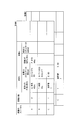
- FIG. 3 represents the facility energy characteristics of the facilities (boundaries) constituting the energy demand facility 2 by a setting table in a two-dimensional matrix format. There is a separate setting table for each facility.
- the setting table of the equipment 1 and the setting table of the equipment 2 are displayed below it.
- the vertical axis direction of the setting table represents the statuses A to C of the equipment.
- the horizontal axis direction of the setting table represents the name and unit of each variable corresponding to each status A to C and the relational expression between each variable and energy.
- FIG. 4 represents the facility energy characteristics of the facilities constituting the energy demand facility 2 in a hierarchical bubble chart.
- each status of equipment can be defined (input) and displayed (output) more dynamically.
- Bubble 4 corresponds to each of the equipment statuses A, B, and C defined in the table of equipment 1 in FIG.
- Bubble SB indicates that the definition is hierarchical.
- Bubble Shalt not shown in FIG. 3 defines a stop state due to an abnormality in the equipment 1 or during maintenance.
- Each facility energy characteristic (demand, distribution, generation) can be described using variables, formulas, and logical description notation (such as “if then else”) defined in the bubble corresponding to each facility status.
- the bubble chart input has an advantage that the route for transitioning between the statuses of the facilities and the boundary condition can be defined.
- “Condition Def. (SC-SB)” in FIG. 4 is an example in which the status is defined for the transition period from the equipment status B to the equipment status C.
- the following information in the equipment energy characteristics can be defined for each equipment and each equipment status.
- -Number of variables-Variable names and units-Number of parameters-Parameter names and units-Relational expressions with energy (variables, parameters) ⁇ Automatic parameter adjustment ⁇ Automatic parameter adjustment conditions (multiple conditions can be selected, such as brand, fixed period, condition match) ⁇ Period value acquisition period
- step S1 and step S2 energy consumption characteristics and energy supply characteristics for each facility and each production brand can be defined in association with the status of the facility.
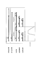
- FIG. 5A is an energy characteristic example diagram generated by these.
- the energy characteristics for each status are displayed.
- the horizontal axis is the time axis.
- five statuses are displayed, and are “planned production time”, “execution production time”, “production time”, “apparatus operation time”, and “production contribution time” from the top.
- Planned production time (POT: Production order time / order duration): Production time set in advance in the production plan.
- -Execution production time (TPT: Throughput time / Execution time): The time during which production activities are performed from the start to the end of production.
- BT Busy time
- BT Busy time
- -Equipment operating time (PCT: Process time): Operating time of equipment used for production regardless of output.
- Production contribution time (PDT: Production time / Main usage time): The time when the output that is the product was produced.
- Equipment setup time (ESUT: Effective setup time): The time to setup the equipment for production.
- Transport time Transport time between devices or transport from the warehouse.
- Wait time Wait time / set aside time
- Delay time Delay time
- Execution production time TPT ⁇ (production time BT + conveyance time TT + standby time WT)
- Production time BT Device operating time PCT + Delay time
- the apparatus setup time ESUT is a status in which the facility (group) is started up from a complete stop state, and shows an example in which the amount of energy used increases with the passage of time.
- the delay time DeT is a status in which the apparatus is temporarily stopped due to a failure or a defect, and shows an example in which large energy equivalent to that at the time of production is consumed.
- the energy consumption gradually decreases after a certain amount of time has elapsed after the temporary stop, and the standby energy is often reduced.
- the transport time TT and the standby time WT are the status of preparation work for changing production to another lot, and the energy usage decreases with the passage of time, and finally becomes the standby energy usage.
- FIG. 5B is a diagram showing the relationship between the status change of the facility 1 and the energy consumption on the time axis.
- the horizontal direction of FIG. 5B is a time axis.
- Equipment 1 in FIG. 5B shall produce a single brand of product.
- the equipment 1 is started in response to the start instruction, enters the operation state after preparation for operation after the instruction for operation, and stops after preparation for stop in response to the stop instruction.
- the energy consumption at this time rises to the rated energy at time t1 after the start instruction, and continues that state until the operation instruction.
- the operation capacity is reduced according to the required production amount over time t2, and the energy is also reduced accordingly. Thereafter, the operation is started.
- the energy characteristics may be different for each brand. For example, when a material is charged into a heating furnace and heated, the heating pattern for heating differs for each brand. In such a case, the energy characteristics are defined by dividing the status during operation for each brand. If the characteristics of the start and stop of the equipment are different depending on the brand, the start characteristics are divided for each brand in the same manner as described above, or all statuses are managed separately by setting the equipment and brand.
- This method makes it possible to have automatic adjustment conditions for model parameters for each equipment and each status. Therefore, for example, it is possible to update the model only for equipment that has undergone maintenance or partial update of the estimated model, such as adjusting the model of a certain production brand. This not only improves energy prediction accuracy but also saves computing resources. The advantage is also obtained.
- step S ⁇ b> 3 the operator acquires production schedule information from a server of an external system (not shown) connected to the energy management apparatus 5.
- the production schedule information is obtained by converting a production plan in each facility into data, and a production schedule of brands and production quantities in each facility is determined based on the production schedule information.
- the acquired production schedule information includes, for example, production brands and production quantities about one day or one week ahead as time series information and is stored in the production schedule information storage unit 5e.
- step S4 the operator inputs the used process variables defined in step S3 (for example, header pressure P, inlet temperature T, etc.) and parameter values in the equation.
- the used process variables defined in step S3 for example, header pressure P, inlet temperature T, etc.
- step S5 the operator confirms whether or not the estimated model is automatically adjusted. If there is no automatic adjustment, the operator proceeds to the process in the subsequent step 6. If there is automatic adjustment, the operator proceeds to the process in step 10 and later described. .
- step S6 when the plant is divided into a plurality of boundaries (equipment (group)), the operator synthesizes the definition of each divided boundary (equipment (group)), so that the entire plant Energy consumption characteristics can be obtained.
- the synthesis method will be described later.
- step S7 the energy management device collects actual energy usage values from the monitoring control system of the boundary (equipment (group)) as the energy management target, and compares it with the assumed energy amount derived from the energy baseline model. The difference is generated as KPI (energy efficiency index).
- KPI energy efficiency index
- step S8 the energy management apparatus repeatedly executes the processes from step S3 to step S7 until all the boundaries (equipment (group)) defined as the energy management target are completed.
- an energy management apparatus displays the calculation result of KPI about all the boundaries (facility (group)) in step S7 on the display screen of GUI display operation part 5b.
- step S5 when it is necessary to automatically adjust the estimation model, the energy management apparatus first performs external factor information acquisition processing in step S10.
- external factor information acquisition processing In defining the facility energy characteristics in step S2, not only plant information but also weather conditions (temperature, humidity, etc.) are assumed to be variables. Therefore, the energy management apparatus can use, for example, an external information input unit as external factor information.
- the weather forecast and actual values are collected from No.4.
- step S11 the energy management apparatus acquires the actual value of the plant information defined by the facility energy characteristics.
- step S12 the energy management apparatus automatically calculates the parameter defined as the facility energy characteristic using the actual values in step S10 and step S11.
- the actual value used for the calculation is a variable defined in step S2.
- Y (k, i) The elapsed time after the status change of the k-th data with respect to an arbitrary equipment status (0 immediately after the status change is assumed to be i), and the estimated energy consumption value of the equipment at that time is assumed to be Y (k, i). . It is assumed that Y (k, i) can be calculated by linear combination of N actually measured data shown in the equation (1).
- ⁇ n (i) is the partial regression coefficient
- Xn (k, i) is the nth data observed to calculate Y (k, i).
- the estimated value obtained by the calculation of the equation (1) is mY (k, i).
- the actual value observed in the k-th i-th time zone is Y (k, i) and the square sum in the learning period of the approximate error of the estimated value for the i-th time zone is Qi, (2)
- the model can be made nonlinear by using a nonlinear regression method.
- the model parameter can be adjusted for each time zone to obtain the estimated energy use value based on the past actual value.
- step S13 the energy management apparatus re-stores the estimated model parameter calculated in step S12 in the estimated model storage unit 5r. Since the correction history is stored in the estimated model storage unit 5r, the estimated model can be returned to an arbitrary state. Alternatively, a predetermined specific model can be used.
- step S13 When the process of step S13 is completed, the process proceeds to step S6.
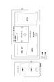
- FIG. 6A is an example of division setting of a plurality of boundaries based on the present invention, and the same reference numerals are given to the parts common to FIG.
- FIG. 6A is an explanation of an interface of the equipment energy characteristic generation unit 5f of FIG.
- the equipment is hierarchically divided into a plurality of boundaries, and each is an energy management object. Each boundary is composed of a plurality of equipment components.
- the energy distribution equipment 1b and the energy demand equipment 2 are each hierarchized as a tree structure with a plurality of equipment components.
- the specific boundary of the energy distribution facility 1b (facility b1-2) and the specific boundary of the energy demand facility 2 (facility 21-2-1 to facility 21-2-4) are displayed in association with each other.
- the energy generation facility 1a may also be hierarchized as a tree structure. Furthermore, the specific boundary of the energy generation facility 1a and the specific boundary of the energy demand facility 2 may be displayed in association with each other. In the aspect of equipment management, it is preferable to refine the tree structure according to the actual equipment configuration, but in the energy management aspect, the degree of decomposition is determined by the ease of measurement and the amount of energy used. .
- the time lag (response time of response time) until the influence when the status of any one of the energy distribution equipment 1b (and / or the energy generation equipment 1a) and the energy demand equipment 2 fluctuates (changes) is propagated to the other. Evaluation and judgment can be made for delay and quantitative influence (response characteristics).
- boundary when managing energy in a factory, energy management objects such as equipment in the factory are divided into several boundaries and modeled by boundary (sub-equipment and sub-equipment group) to manage energy use efficiency.
- You may determine a boundary so that it may manage in units, such as an organization and a building.
- the boundary may be determined in consideration of energy usage, ease of measurement, and the like. Initially, management may be performed for the entire building, and then managed separately for “equipment that consumes significant energy” and “others”, and may be managed separately for “others”. Specifically, for example, the heating furnace uses a large amount of energy, so the apparatus is managed as a boundary.
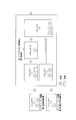
- FIG. 6B is an example of setting the boundary at the first stage.
- the boundary 1 is divided into utility facilities
- the boundary 2 is divided into a heating furnace
- the boundary 3 is divided into other manufacturing facilities and three boundaries.
- boundary 1 is divided into two boundaries
- boundary 3 is divided into three boundaries.
- the arrows between the boundaries indicate the flow of things and energy. Moreover, it is shown that facilities and apparatuses are mixed in the boundary.
- the first method focuses on the individual equipment in the boundary, each input / output condition, external response condition (behavior), capability range, internal operation status (status) type and definition, and operation Describe individually the order, temporal properties, information related to energy measurement, information related to energy variable measurement, etc., and perform parallel calculations as multiple independent estimation model groups to simultaneously evaluate each energy characteristic To do.
- the discrepancy between the calculation result of the estimated model group and the actual value can be a means for extracting improvement issues regarding the local cooperation between the facilities in the boundary area and the coupling conditions.
- the second method includes information such as individual facilities and equipment in the boundary, as well as input / output conditions, external response conditions (behavior), capability range when looking outside from the entire boundary area, Describes the type and definition of the internal operating state (status), the order and temporal properties of the operation, information related to energy measurement, and information related to measurement of variables related to energy. That is, the estimation model is constructed (synthesized) by regarding the entire set boundary area as a virtual single facility.
- the next step is to switch to the second method and further expand the scope of energy management. It can be a way to achieve optimization.
- Examples of external input / output conditions include definitions of raw materials and products.
- the raw material corresponds to electric energy or gas
- the product corresponds to cold water or hot water.
- Cold water is used not only for air conditioning but also as production cooling water.
- raw materials include parts to be processed, electric power energy, and production cooling water
- products include processed parts and the like. This processed part is treated as a raw material for the final assembly line. Such a relationship is described.
- the first method alone is not practical because it requires too much cost and labor. Therefore, in general, only the equipment groups related to “significant energy consumption” are picked up in the boundary, and the first method is applied to only those equipment groups, and many other equipment groups are the second. That is, it is configured as an estimation model that describes the behavior of the entire boundary, not individual equipment.
- the boundary configuration of the nested or hierarchical estimation model can effectively achieve energy efficiency according to the management purpose and management policy. Considering the trade-offs between cost, effort, and the effect obtained, it is important to set the optimal boundary granularity and design the overall structure.
- the boundary setting granularity of the estimation model should be low (coarse).
- the boundary setting granularity of the estimation model should be low (coarse).
- all equipment generally name of production equipment using energy such as facilities, equipment, equipment, equipment, and elements
- statuses related to changes in energy consumption and / or energy supply amount respectively. Describes the relationship between the amount of energy used and / or the variable related to energy supply, and the amount of energy used by the facility with the function to define the calculation formula or conditional expression for calculating the energy usage and / or energy supply And / or a facility model function capable of estimating and calculating energy supply.
- variable means the instruction (value) from the outside that specifies the operating condition of the equipment, the measured value related to the equipment operation, the information related to the internal operation of the equipment, the time information and the operating time from the status change. Including.
- the facility model function has at least a facility information definition function that can describe the status that the facility is in operation and the rated energy consumption or rated energy supply amount at that time.
- the difference between the actual energy usage or energy supply during operation of the equipment and the estimated energy usage is evaluated.
- the following estimation model (equipment energy characteristics) is corrected based on actual energy information.
- the condition for correcting the estimated model is that there is no abnormal state of the equipment or that the equipment has been repaired.
- the following “automatic correction” and “manual correction” can be selected or combined for each equipment. It is also possible to automatically correct only the estimated model of the specific equipment or to prohibit the correction of the estimated model of the specific equipment. Since the correction history of the estimation model is sequentially stored, it can be returned to the designated time as necessary.
- A The estimated model (equipment energy characteristics) is automatically corrected by moving average, total average, etc., using statistical values of the relationship between variables and energy.
- B Using the one-shot data for the period from when the specified condition is satisfied to when the specified condition is satisfied, the facility energy characteristic for each status is calculated to automatically correct the estimated model.
- C The estimated model is automatically corrected using the statistical value of the time series data for the period from when the specified condition is satisfied until the specified condition is satisfied. However, this applies when the equipment energy characteristics change with time as a variable.
- Manual correction Using the past trend data, the estimated model is corrected using the data for the specified period.
- the reduction effect of the energy consumption and / or the energy supply amount due to the repair of the equipment can be calculated as a ratio or absolute amount. 1) Ratio (ratio of energy consumption (and energy supply) per unit time) (example: kW / kW) 2) Absolute amount of energy reduction (eg kWh)
- the abnormal state of the energy usage amount and the energy supply amount can also be determined. 1) When the deviation exceeds the defined deviation 2) Comparison at the defined comparison timing
- a standard index can be created.
- KPI energy efficiency such as absolute amount of reduction and reduction ratio in energy saving operation
- the assumed energy amount corresponding to these can be simulated more accurately.
- the assumed energy amount is a future energy consumption trend based on the production plan.
- the energy-based line model can be automatically corrected when the specified conditions are met. This can be done according to the granularity of the model definition, such as for each facility, each status, each production brand, etc. Therefore, it is possible to make partial model adjustments instead of the entire model, and it can be expected to improve prediction accuracy and effectively use computer resources.
- FIG. 7 is a diagram in which the operator assigns the equipment operation plan based on the production plan as shown in the middle part of FIG.
- the upper part of FIG. 7 displays the production plan.
- the middle part of FIG. 7 graphically displays the usage plan for each facility.
- FIG. 5B is expanded.
- the lower part of FIG. 7 displays future power consumption trend predictions.
- 1/30/9 is the current time. Since energy consumption trends are defined for each equipment operation status as shown in FIG. 5B, the future energy consumption trends can be calculated by integrating the consumption of all equipment according to this equipment plan. It can be obtained and displayed in the lower row.
- the danger of demand over can be detected early.
- the upper straight line indicates the contract power amount.
- the present invention can be widely applied to energy management objects such as factories and plants that want to improve energy use efficiency.
Landscapes
- Business, Economics & Management (AREA)
- Engineering & Computer Science (AREA)
- Human Resources & Organizations (AREA)
- Strategic Management (AREA)
- Economics (AREA)
- Entrepreneurship & Innovation (AREA)
- General Physics & Mathematics (AREA)
- Physics & Mathematics (AREA)
- General Business, Economics & Management (AREA)
- Marketing (AREA)
- Tourism & Hospitality (AREA)
- Theoretical Computer Science (AREA)
- Development Economics (AREA)
- Operations Research (AREA)
- Quality & Reliability (AREA)
- Game Theory and Decision Science (AREA)
- Educational Administration (AREA)
- Health & Medical Sciences (AREA)
- Primary Health Care (AREA)
- General Health & Medical Sciences (AREA)
- Water Supply & Treatment (AREA)
- Public Health (AREA)
- Manufacturing & Machinery (AREA)
- Automation & Control Theory (AREA)
- General Engineering & Computer Science (AREA)
- Management, Administration, Business Operations System, And Electronic Commerce (AREA)
- General Factory Administration (AREA)
- Heat-Pump Type And Storage Water Heaters (AREA)
Abstract
Description
本願は、2011年2月28日に出願された日本国特許出願第2011-042413号に基づき優先権を主張し、その内容をここに援用する。
近年、地球温暖化を防止するための温室効果ガスの削減と、限りある資源を有効利用することが強く求められている。そこで、電気、燃料、蒸気、熱、圧縮空気などの各種エネルギーを使用するのにあたり、これらのエネルギーをより効率よく利用するために、様々なエネルギー管理技術が提案され、実用化されている。
なお、以下の説明において、「エネルギー」とは、ISO50001の定義と同様に、電気、燃料、蒸気、熱、圧縮空気およびその他類似の媒体をいう。
「機器」とは、器具、器械、機構の総称である。モータやポンプなどが機器の例である。
「デバイス」とは、特定の機能を有す装置、器具である。設備や機器の構成物として用いられる。蒸気流量センサーやバルブなどが例としてあげられる。
はじめに、ステップS1において、GUI表示操作部5bに設けられている設定GUI画面を介して、オペレータが、エネルギー管理対象とする設備の定義を行う。設定GUI画面は、GUI表示操作部5bに設けられており、どこまでの設備をひとまとまりとするか、すなわち前述のバウンダリとして定義するかをグラフィカルに定義するための画面である。この設定GUI画面により、設備の名称、運転ステータス、時間スケジューリングなどの登録、変更、削除が行える。この定義機能により、設備毎、生産銘柄毎、運転ステータス毎のタイムチャートが完成する。
・変数の数
・変数名称と単位
・パラメータ数
・パラメータ名称と単位
・エネルギーとの関係式(変数、パラメータ)
・パラメータ自動調整の有無
・パラメータ自動調整条件(銘柄、一定周期、条件合致など複数の条件選択可能)
・実績値取得期間
・計画生産時間(POT:Production order time / order duration):あらかじめ生産計画で設定する生産時間。
・実行生産時間(TPT:Throughput time / Execution time):生産開始から終了までの生産活動を行っている時間。
・生産時間(BT:Busy time):1回(ロット)の生産運転に費やされた時間。
・装置稼働時間(PCT:Process time):アウトプットにかかわらず生産に使用する装置の稼働時間。
・生産寄与時間(PDT:Production time / Main usage time):製品となるアウトプットを生産した時間。
・装置セットアップ時間(ESUT:Effective setup time):生産のために装置をセットアップする時間。
・搬送時間(TT:Transportation time):装置間の搬送あるいは倉庫からの搬送時間。
・待機時間(WT:Wait time / set aside time):脇置き時間、次工程搬送待ち時間。
・遅延時間(DeT:Delay time):故障、欠陥により装置を止めた時間。
さらに、これらの相互関係は下記のように定義される。
・実行生産時間TPT=Σ(生産時間BT+搬送時間TT+待機時間WT)
・生産時間BT=装置稼働時間PCT+遅延時間DeT
・装置稼働時間PCT=生産寄与時間PDT+装置セットアップ時間ESUT



各時間帯iごとに(3)式のN元連立方程式を解いて偏回帰係数αn(i)を求めることができる。
ツリー構造への分解は、設備の管理という側面では実際の設備構成に合わせて詳細化するほうが好ましいが、エネルギー管理の側面では、計測の容易性やエネルギー使用量の大きさで分解の程度を決める。
A:変数とエネルギーの関係の統計値を用い、移動平均、総平均などで自動的に推定モデル(設備エネルギー特性)を修正する。
B:指定した条件成立後から、指定した条件成立までの期間のワンショットデータを用いて、ステータスごとの設備エネルギー特性を算出して推定モデルを自動的に修正する。
C:指定した条件成立後から、指定した条件成立までの期間の時系列データの統計値を用いて自動的に推定モデルを修正する。ただし、時間を変数として設備エネルギー特性が変化する場合に適用する。
2)手動修正
過去のトレンドデータを用い、指定した期間のデータを用いて推定モデルの修正を行う。
1)比率(単位時間当たりのエネルギー使用量(およびエネルギー供給量)の比(例:kW/kW)
2)エネルギー削減量の絶対量(例:kWh)
1)定義された偏差を上回った場合
2)定義された比較タイミングで比較
以上、本発明の好適な実施形態について説明し例証したが、これらはあくまで発明の例示であって限定的に考慮されるべきものではなく、追加、削除、置換及び他の変更は本発明の範囲を逸脱しない範囲で可能である。即ち、本発明は前述した実施形態により限定されるものではなく、以下のクレームの範囲により限定されるものである。
1a エネルギー生成設備(エネルギー管理対象物)
1as 監視制御システム(監視部)
1b エネルギー分配設備(エネルギー管理対象物)
1bs 監視制御システム(監視部)
2 エネルギー需要設備(エネルギー管理対象物)
2s 監視制御システム(監視部)
3 通信ネットワーク
4 外部情報入力部
5 エネルギー管理装置
5a 設備外部情報インターフェース部
5b GUI表示操作部
5c 一次情報インターフェース部
5d 生産スケジュール取得部
5e 生産スケジュール格納部
5f 設備エネルギー特性生成部(推定モデル定義部)
5g 設備情報取得部
5h 設備情報格納部
5i 外部変動因子情報取得部
5j 外部変動因子情報格納部
5k 設備エネルギー特性調整部(推定モデル修正部)
5m 設備実績値格納部
5n 設備エネルギー特性検証部
5p 二次情報インターフェース部
5q 設備エネルギー特性合成部
5r 推定モデル格納部
Claims (21)
- エネルギー管理対象物を特定するステップと、
前記エネルギー管理対象物の時間遷移しうるステータスをモニタリングするステップと、
前記エネルギー管理対象物の少なくとも1つのステータスに対応する、前記エネルギー管理対象物の稼動に伴うエネルギー消費量およびエネルギー変換量を推定するための少なくとも1つの推定モデルを定義するステップと、
を含む、エネルギー管理方法。 - 前記推定モデルを定義するステップは、前記エネルギー管理対象物の複数の異なるステータスの各々に対応する、複数の前記推定モデルを定義するステップである、請求項1に記載のエネルギー管理方法。
- 前記複数の推定モデルに基づいて、前記エネルギー管理対象物の稼動に伴うエネルギー消費量およびエネルギー変換量を推定するステップ
を更に含む、請求項2に記載のエネルギー管理方法。 - 前記エネルギー管理対象物は、デバイス、機器、装置、設備、施設、工程ライン、工場の少なくとも1つを含む、請求項1に記載のエネルギー管理方法。
- 前記エネルギー管理対象物を、複数のバウンダリに分割するステップ、
を更に含み、
前記モニタリングするステップは、前記複数のバウンダリのうち少なくとも1つの時間遷移しうるステータスをモニタリングし、
前記推定モデルを定義するステップは、前記バウンダリの少なくとも1つのステータスに対応する、少なくとも1つの推定モデルを定義する、
請求項1に記載のエネルギー管理方法。 - 前記推定モデルを、前記複数の異なるステータスの各々におけるエネルギー消費量およびエネルギー変換量の少なくとも1つの実測値に基づき修正するステップ、
を更に含む、請求項1に記載のエネルギー管理方法。 - 前記推定モデルを修正するステップは、
前記推定モデルの自動修正の可/否の選択をすることと、
前記推定モデルの修正の履歴を複数保存し、修正前の前記推定モデルの選択を可能とすることと、
を含む、請求項6に記載のエネルギー管理方法。 - 設備の1つのステータスに対応する前記推定モデルを、銘柄ごとに分けて定義することを特徴とする、請求項2に記載のエネルギー管理方法。
- 前記推定モデルは、異なる設備のバウンダリを二個以上関連付けて合成される複合モデルであることを特徴とする、請求項1に記載のエネルギー管理方法。
- 稼動することによりエネルギーを消費または変換するエネルギー管理対象物のエネルギー消費量およびエネルギー変換量を実測し、前記エネルギー管理対象物の時間遷移しうるステータスをモニタリングする監視部と、
前記エネルギー管理対象物の少なくとも1つのステータスに対応する、前記エネルギー管理対象物の稼動に伴うエネルギー消費量およびエネルギー変換量を推定するための少なくとも1つの推定モデルを定義する推定モデル定義部と、
前記推定モデルを格納する推定モデル格納部と、
前記推定モデル格納部に格納されている前記推定モデルを、前記エネルギー管理対象物の稼動に伴う前記エネルギー消費量および前記エネルギー変換量に基づき修正し、前記推定モデル格納部に格納する推定モデル修正部と、
を備える、エネルギー管理装置。 - 前記監視部は、前記エネルギー管理対象物を分割することによって生成される複数のバウンダリの各々のエネルギー消費量およびエネルギー変換量を実測し、前記複数のバウンダリの各々の時間遷移しうるステータスをモニタリングし、
前記推定モデル定義部は、前記複数のバウンダリの各々の少なくとも1つのステータスに対応する、前記複数のバウンダリの各々の稼動に伴うエネルギー消費量およびエネルギー変換量を推定するための少なくとも1つの推定モデルを定義し、
前記推定モデル修正部は、前記推定モデルを、前記複数のバウンダリの各々の稼動に伴う前記エネルギー消費量および前記エネルギー変換量に基づき修正し、前記推定モデル格納部に格納する、
請求項10に記載のエネルギー管理装置。 - エネルギー生成設備、エネルギー分配設備、エネルギー需要設備、の中から、複数のエネルギー管理対象物を特定するステップと、
前記エネルギー管理対象物の時間遷移しうるステータスをモニタリングするステップと、
前記エネルギー管理対象物の1つのステータスに対応する推定モデルを定義するステップと、
定義された前記推定モデルに基づいて、前記エネルギー管理対象物の稼動に伴うエネルギー消費量およびエネルギー変換量を推定するステップと、
前記エネルギー需要設備を含む第1のバウンダリと、前記エネルギー生成設備およびエネルギー分配設備の少なくとも1つを含む第2のバウンダリと、を互いに関連付けて表示する表示ステップと、
を含む、エネルギー管理システムのGUI方法。 - 前記表示ステップにおいて、一次情報である過去の設備エネルギー値と、前記一次情報にもとづいて加工または生成された二次情報と、が分別して表示される、
請求項12に記載のエネルギー管理システムのGUI方法。 - 前記表示ステップにおいて、前記一次情報のみを扱う第1の表示・操作用ウィンドウ画面と、前記二次情報のみを扱う第2の表示・操作用ウィンドウ画面と、が系統分けて表示される、
請求項13に記載のエネルギー管理システムのGUI方法。 - 前記表示ステップにおいて、前記ステータスが、動的な状態遷移図で表示される、
請求項12に記載のエネルギー管理システムのGUI方法。 - 前記動的な状態遷移図は、前記エネルギー管理対象物のバウンダリ内設備と対応させた階層構造のバブルチャートである、
請求項15に記載のエネルギー管理システムのGUI方法。 - 前記バブルチャートは、
前記エネルギー対象物の稼動に伴い時間軸上を推移するそれぞれの前記設備ステータスに対応する入力定義および/または出力表示を行うバブルと、
任意の前記バブル間を接続してこれらの設備ステータス間で遷移経路を特定する状態移行ルートと、
を含み、
前記状態移行ルートは、前記任意の設備ステータス間の移行期間中の状態を、境界条件として定義できる、
請求項15に記載のエネルギー管理システムのGUI方法。 - 前記エネルギー管理対象物は、生産スケジュール情報に基づいて稼動し、
前記推定モデルおよび前記生産スケジュール情報に基づいて将来の前記エネルギー消費量および前記エネルギー変換量を推定するステップ、
を更に含む、請求項1に記載のエネルギー管理方法。 - 生産スケジュールに基づいて稼動し、稼動することによりエネルギーを消費および変換する、エネルギー管理設備と、
前記エネルギー管理設備の時間遷移しうるステータス、エネルギー消費量およびエネルギー変換量をモニタリングする監視部と、
外部情報を取得して出力する外部情報入力部と、
前記外部情報に基づいて、前記エネルギー管理設備における前記エネルギー消費量および前記エネルギー変換量を管理するためのエネルギー管理装置と、
を備える、エネルギー管理システムであって、
前記エネルギー管理装置は、
前記生産スケジュール情報を格納する、生産スケジュール情報格納部と、
前記エネルギー管理設備の設備情報を格納する、設備情報格納部と、
前記外部情報入力部が取得した前記外部情報を格納する、外部変動因子情報格納部と、
前記監視部から前記エネルギー管理設備のエネルギー消費量およびエネルギー変換量を設備実績値として受信して格納する、設備実績値格納部と、
前記エネルギー管理対象物を複数のバウンダリに分割するバウンダリ設定部と、
前記生産スケジュール情報、前記設備情報、前記設備実績値に基づき、前記複数のバウンダリの各々における、少なくとも1つの前記ステータスに対応する、エネルギー消費量およびエネルギー変換量を推定するための複数の推定モデルを定義する、推定モデル定義部と、
前記設備実績値および前記外部情報に基づき、前記複数の推定モデルを修正する、推定モデル修正部と、
前記推定モデル修正部で修正された前記複数の推定モデルを合成してGUIで表示する、GUI表示部と、
を備える、エネルギー管理システム。 - 前記GUI表示部は、前記推定モデルおよび前記生産スケジュール情報に基づいて、将来の前記エネルギー消費量および前記エネルギー変換量を推定して表示する、
請求項19に記載のエネルギー管理システム。 - 比較の基準となるベースライン期間の、任意の前記バウンダリのエネルギー消費量および前記エネルギー変換量とこれらのエネルギーに関連する変数の関係と、報告期間の前記バウンダリのエネルギー消費量およびエネルギー変換量とこれらのエネルギーに関連する変数の関係とを比較した性能指標をGUI表示する、請求項19に記載のエネルギー管理システム。
Priority Applications (5)
| Application Number | Priority Date | Filing Date | Title |
|---|---|---|---|
| SG2013064456A SG192951A1 (en) | 2011-02-28 | 2012-02-28 | Energy management method and system thereof, and gui method |
| CN201280010472.4A CN103384893B (zh) | 2011-02-28 | 2012-02-28 | 能量管理方法及其系统以及gui方法 |
| JP2013502360A JP6109066B2 (ja) | 2011-02-28 | 2012-02-28 | エネルギー管理方法 |
| EP12751721.7A EP2682914A4 (en) | 2011-02-28 | 2012-02-28 | ENERGY MANAGEMENT METHOD AND SYSTEM THEREFOR AND METHOD FOR A GRAPHIC USER INTERFACE |
| US14/001,823 US20130338842A1 (en) | 2011-02-28 | 2012-02-28 | Energy management method and system thereof, and gui method |
Applications Claiming Priority (2)
| Application Number | Priority Date | Filing Date | Title |
|---|---|---|---|
| JP2011042413 | 2011-02-28 | ||
| JP2011-042413 | 2011-02-28 |
Publications (1)
| Publication Number | Publication Date |
|---|---|
| WO2012118067A1 true WO2012118067A1 (ja) | 2012-09-07 |
Family
ID=46757999
Family Applications (1)
| Application Number | Title | Priority Date | Filing Date |
|---|---|---|---|
| PCT/JP2012/054897 Ceased WO2012118067A1 (ja) | 2011-02-28 | 2012-02-28 | エネルギー管理方法およびそのシステム並びにgui方法 |
Country Status (6)
| Country | Link |
|---|---|
| US (1) | US20130338842A1 (ja) |
| EP (1) | EP2682914A4 (ja) |
| JP (1) | JP6109066B2 (ja) |
| CN (1) | CN103384893B (ja) |
| SG (1) | SG192951A1 (ja) |
| WO (1) | WO2012118067A1 (ja) |
Cited By (17)
| Publication number | Priority date | Publication date | Assignee | Title |
|---|---|---|---|---|
| JP2012230461A (ja) * | 2011-04-25 | 2012-11-22 | Toshiba Mitsubishi-Electric Industrial System Corp | スケジューリング装置、及びスケジューリング方法 |
| CN103136895A (zh) * | 2013-01-25 | 2013-06-05 | 东北大学 | 一种电熔镁砂熔炼过程的群炉能耗报警系统及方法 |
| EP2779040A1 (en) * | 2013-03-15 | 2014-09-17 | Honeywell International Inc. | Modeling energy conversion in systems |
| EP2840535A1 (en) * | 2013-08-23 | 2015-02-25 | Yokogawa Electric Corporation | Operation plan decision method and operation plan decision system |
| WO2015069056A1 (ko) * | 2013-11-08 | 2015-05-14 | 한양대학교 에리카산학협력단 | 전력 관리 방법 및 시스템 |
| KR20150053704A (ko) * | 2013-11-08 | 2015-05-18 | 한양대학교 에리카산학협력단 | 전력 관리 방법 및 시스템 |
| JP2016045570A (ja) * | 2014-08-20 | 2016-04-04 | 三菱電機株式会社 | 節電量算出装置 |
| JP2017142674A (ja) * | 2016-02-10 | 2017-08-17 | 富士電機株式会社 | 制御装置、制御システム、制御プログラム、及び制御方法 |
| JP2020009290A (ja) * | 2018-07-11 | 2020-01-16 | 三菱電機ビルテクノサービス株式会社 | 設備選択支援装置及びプログラム |
| JP2020173577A (ja) * | 2019-04-10 | 2020-10-22 | 富士電機株式会社 | 情報処理装置、情報処理方法、プログラム |
| US10990067B2 (en) | 2016-07-07 | 2021-04-27 | Aspen Technology, Inc. | Computer system and method for the dynamic construction and online deployment of an operation-centric first-principles process model for predictive analytics |
| CN115248063A (zh) * | 2021-04-28 | 2022-10-28 | 横河电机株式会社 | 评价装置、评价方法、记录有评价程序的记录介质、控制装置及记录有控制程序的记录介质 |
| US11630446B2 (en) | 2021-02-16 | 2023-04-18 | Aspentech Corporation | Reluctant first principles models |
| US11754998B2 (en) | 2019-10-18 | 2023-09-12 | Aspentech Corporation | System and methods for automated model development from plant historical data for advanced process control |
| US11782401B2 (en) | 2019-08-02 | 2023-10-10 | Aspentech Corporation | Apparatus and methods to build deep learning controller using non-invasive closed loop exploration |
| US11853032B2 (en) | 2019-05-09 | 2023-12-26 | Aspentech Corporation | Combining machine learning with domain knowledge and first principles for modeling in the process industries |
| US11934159B2 (en) | 2018-10-30 | 2024-03-19 | Aspentech Corporation | Apparatus and methods for non-invasive closed loop step testing with controllable optimization relaxation |
Families Citing this family (16)
| Publication number | Priority date | Publication date | Assignee | Title |
|---|---|---|---|---|
| TWI525560B (zh) * | 2013-11-07 | 2016-03-11 | 財團法人資訊工業策進會 | 效能管理系統、方法與其電腦可讀取記錄媒體 |
| JP5930225B2 (ja) * | 2014-01-27 | 2016-06-08 | 横河電機株式会社 | エネルギー効率評価支援装置、コンピュータプログラムおよびエネルギー効率評価支援方法 |
| JP6234295B2 (ja) * | 2014-03-26 | 2017-11-22 | 三菱電機株式会社 | 欠測データ補完方法およびデータ収集装置 |
| JP6038085B2 (ja) * | 2014-08-28 | 2016-12-07 | 横河電機株式会社 | 産業用デマンドレスポンス制御システムおよび産業用デマンドレスポンス制御方法 |
| CN105446163B (zh) * | 2014-08-29 | 2019-07-26 | 国家电网公司 | 一种基于不同能源类型的微网全能流建模方法 |
| KR101641258B1 (ko) * | 2014-10-10 | 2016-07-20 | 엘지전자 주식회사 | 설비를 관제하는 중앙 제어 장치, 이를 포함하는 설비 제어 시스템 및 설비 제어 방법 |
| CN105807736A (zh) * | 2014-12-27 | 2016-07-27 | 上海麦杰环境科技有限公司 | 污染物智能核算方法 |
| US10466663B2 (en) | 2015-01-22 | 2019-11-05 | Siemens Industry, Inc. | Systems, methods and apparatus for an improved interface to energy management systems |
| JP6498976B2 (ja) * | 2015-03-20 | 2019-04-10 | 株式会社東芝 | 推定装置、推定方法およびコンピュータプログラム |
| CN105204433B (zh) * | 2015-09-30 | 2017-11-28 | 重庆大学 | 一种随机加工间隔内机床状态切换的机床节能运行方法 |
| JP6880843B2 (ja) * | 2017-03-09 | 2021-06-02 | オムロン株式会社 | 管理装置および管理プログラム |
| JP6839277B2 (ja) * | 2017-05-29 | 2021-03-03 | 京セラ株式会社 | 管理方法及び管理装置 |
| EP3511879A1 (en) * | 2018-01-12 | 2019-07-17 | Siemens Aktiengesellschaft | Method for monitoring and controlling the energy cost for the production of a product lot |
| US20220327395A1 (en) * | 2019-09-03 | 2022-10-13 | Nippon Telegraph And Telephone Corporation | Data analyzing apparatus, method, and program |
| EP3992871A1 (en) * | 2020-10-30 | 2022-05-04 | Bayer AG | Energy management system for batch production processes |
| JP7774297B2 (ja) | 2022-02-21 | 2025-11-21 | i Smart Technologies株式会社 | エネルギ管理システム |
Citations (5)
| Publication number | Priority date | Publication date | Assignee | Title |
|---|---|---|---|---|
| JP2002236724A (ja) * | 2001-02-08 | 2002-08-23 | Yamatake Corp | エネルギー取引システム |
| JP2002259508A (ja) * | 2001-03-05 | 2002-09-13 | Hitachi Ltd | エネルギー監視システム |
| JP2007018322A (ja) | 2005-07-08 | 2007-01-25 | Yamatake Corp | 省エネルギー量推定装置、方法、およびプログラム |
| JP2009009399A (ja) * | 2007-06-28 | 2009-01-15 | Yokogawa Electric Corp | プラント運転データ管理システム |
| JP2009238246A (ja) * | 2009-07-13 | 2009-10-15 | Takasago Thermal Eng Co Ltd | 建物設備管理の分析装置 |
Family Cites Families (25)
| Publication number | Priority date | Publication date | Assignee | Title |
|---|---|---|---|---|
| US4920499A (en) * | 1987-09-30 | 1990-04-24 | E. I. Du Pont De Nemours And Company | Expert system with natural-language rule updating |
| US20030009401A1 (en) * | 2001-04-27 | 2003-01-09 | Enerwise Global Technologies, Inc. | Computerized utility cost estimation method and system |
| US7089190B2 (en) * | 2001-05-18 | 2006-08-08 | Power Resource Managers, Llp | System and method for managing utility power use |
| US7552033B1 (en) * | 2001-12-20 | 2009-06-23 | The Texas A&M University System | System and method for diagnostically evaluating energy consumption systems and components of a facility |
| AU2002348737B2 (en) * | 2002-12-19 | 2008-04-17 | Council Of Scientific And Industrial Research | An energy efficient data acquisition system and a computer controlled energy monitoring system incorporating the same |
| JP2004227054A (ja) * | 2003-01-20 | 2004-08-12 | Daikin Ind Ltd | エネルギー管理システム、エネルギー管理装置およびエネルギー管理プログラム |
| JP2004280172A (ja) * | 2003-03-12 | 2004-10-07 | Seiko Epson Corp | エネルギー評価支援システム、プログラム、情報記憶媒体およびエネルギー評価支援方法 |
| JP2004280618A (ja) * | 2003-03-18 | 2004-10-07 | Hitachi Ltd | エネルギー管理システム |
| US7085660B2 (en) * | 2003-05-13 | 2006-08-01 | Siemens Power Transmission & Distribution, Inc. | Energy management system in a power and distribution system |
| US7043380B2 (en) * | 2003-09-16 | 2006-05-09 | Rodenberg Iii Ernest Adolph | Programmable electricity consumption monitoring system and method |
| US7317404B2 (en) * | 2004-01-14 | 2008-01-08 | Itron, Inc. | Method and apparatus for collecting and displaying consumption data from a meter reading system |
| CN1648922A (zh) * | 2005-03-03 | 2005-08-03 | 南京科远控制工程有限公司 | 企业管控一体化管理信息控制方法 |
| JP2007264704A (ja) * | 2006-03-27 | 2007-10-11 | Yokogawa Electric Corp | エネルギー管理システム |
| WO2007139587A1 (en) * | 2006-05-26 | 2007-12-06 | The Board Of Regents Of The Nevada System Of Higher Education On Behalf Of The Desert Research Institute | Utility monitoring systems and methods of use |
| US8396608B2 (en) * | 2007-09-24 | 2013-03-12 | Budderfly Ventures Llc | Computer based energy management |
| US8965719B1 (en) * | 2008-03-07 | 2015-02-24 | Versify Solutions, Inc. | Universal performance monitor for power generators |
| US8260469B2 (en) * | 2008-11-04 | 2012-09-04 | Green Energy Corporation | Distributed hybrid renewable energy power plant and methods, systems, and comptuer readable media for controlling a distributed hybrid renewable energy power plant |
| EP2204712A1 (en) * | 2008-12-17 | 2010-07-07 | Bayer MaterialScience AG | Method and system for monitoring and analysing energy consumption in operated chemical plants |
| US20100275147A1 (en) * | 2009-04-24 | 2010-10-28 | Rockwell Automation Technologies, Inc. | Industrial energy demand management and services |
| EA201100511A1 (ru) * | 2009-06-26 | 2011-10-31 | Масат Б.В. | Способ и система обнаружения местонахождения подвижного сенсорного узла сети |
| CN102193528B (zh) * | 2010-03-05 | 2013-08-14 | 朗德华信(北京)自控技术有限公司 | 基于云计算的能源管理控制系统及方法 |
| WO2011162576A2 (ko) * | 2010-06-25 | 2011-12-29 | 엘지전자 주식회사 | 네트워크 시스템 |
| US8880202B2 (en) * | 2010-07-09 | 2014-11-04 | Emerson Process Management Power & Water Solutions, Inc. | Optimization system using an iteratively coupled expert engine |
| US9335748B2 (en) * | 2010-07-09 | 2016-05-10 | Emerson Process Management Power & Water Solutions, Inc. | Energy management system |
| CN101980262A (zh) * | 2010-10-14 | 2011-02-23 | 冶金自动化研究设计院 | 一种基于计算机的钢铁企业能源仿真平台 |
-
2012
- 2012-02-28 WO PCT/JP2012/054897 patent/WO2012118067A1/ja not_active Ceased
- 2012-02-28 SG SG2013064456A patent/SG192951A1/en unknown
- 2012-02-28 CN CN201280010472.4A patent/CN103384893B/zh not_active Expired - Fee Related
- 2012-02-28 JP JP2013502360A patent/JP6109066B2/ja not_active Expired - Fee Related
- 2012-02-28 US US14/001,823 patent/US20130338842A1/en not_active Abandoned
- 2012-02-28 EP EP12751721.7A patent/EP2682914A4/en not_active Ceased
Patent Citations (5)
| Publication number | Priority date | Publication date | Assignee | Title |
|---|---|---|---|---|
| JP2002236724A (ja) * | 2001-02-08 | 2002-08-23 | Yamatake Corp | エネルギー取引システム |
| JP2002259508A (ja) * | 2001-03-05 | 2002-09-13 | Hitachi Ltd | エネルギー監視システム |
| JP2007018322A (ja) | 2005-07-08 | 2007-01-25 | Yamatake Corp | 省エネルギー量推定装置、方法、およびプログラム |
| JP2009009399A (ja) * | 2007-06-28 | 2009-01-15 | Yokogawa Electric Corp | プラント運転データ管理システム |
| JP2009238246A (ja) * | 2009-07-13 | 2009-10-15 | Takasago Thermal Eng Co Ltd | 建物設備管理の分析装置 |
Non-Patent Citations (1)
| Title |
|---|
| See also references of EP2682914A4 |
Cited By (32)
| Publication number | Priority date | Publication date | Assignee | Title |
|---|---|---|---|---|
| JP2012230461A (ja) * | 2011-04-25 | 2012-11-22 | Toshiba Mitsubishi-Electric Industrial System Corp | スケジューリング装置、及びスケジューリング方法 |
| CN103136895A (zh) * | 2013-01-25 | 2013-06-05 | 东北大学 | 一种电熔镁砂熔炼过程的群炉能耗报警系统及方法 |
| EP2779040A1 (en) * | 2013-03-15 | 2014-09-17 | Honeywell International Inc. | Modeling energy conversion in systems |
| EP2840535A1 (en) * | 2013-08-23 | 2015-02-25 | Yokogawa Electric Corporation | Operation plan decision method and operation plan decision system |
| US10007878B2 (en) | 2013-08-23 | 2018-06-26 | Yokogawa Electric Corporation | Operation plan decision method and operation plan decision system |
| KR20150095601A (ko) * | 2013-11-08 | 2015-08-21 | 한양대학교 에리카산학협력단 | 전력 관리 방법 및 시스템 |
| KR20150053704A (ko) * | 2013-11-08 | 2015-05-18 | 한양대학교 에리카산학협력단 | 전력 관리 방법 및 시스템 |
| KR101589231B1 (ko) * | 2013-11-08 | 2016-01-28 | 한양대학교 에리카산학협력단 | 전력 관리 방법 및 시스템 |
| KR101654555B1 (ko) * | 2013-11-08 | 2016-09-06 | 한양대학교 에리카산학협력단 | 전력 관리 방법 및 시스템 |
| WO2015069056A1 (ko) * | 2013-11-08 | 2015-05-14 | 한양대학교 에리카산학협력단 | 전력 관리 방법 및 시스템 |
| US10180668B2 (en) | 2013-11-08 | 2019-01-15 | Industry-University Cooperation Foundation Hanyang University Erica Campus | Method and system for managing power |
| JP2016045570A (ja) * | 2014-08-20 | 2016-04-04 | 三菱電機株式会社 | 節電量算出装置 |
| JP2017142674A (ja) * | 2016-02-10 | 2017-08-17 | 富士電機株式会社 | 制御装置、制御システム、制御プログラム、及び制御方法 |
| US10990067B2 (en) | 2016-07-07 | 2021-04-27 | Aspen Technology, Inc. | Computer system and method for the dynamic construction and online deployment of an operation-centric first-principles process model for predictive analytics |
| JP2021101388A (ja) * | 2016-07-07 | 2021-07-08 | アスペン テクノロジー インコーポレイテッド | 予測分析用の動作中心型第一原理プロセスモデルの動的構築及びオンライン配備のためのコンピュータシステム及び方法 |
| JP7394805B2 (ja) | 2016-07-07 | 2023-12-08 | アスペンテック・コーポレーション | 予測分析用の動作中心型第一原理プロセスモデルの動的構築及びオンライン配備のためのコンピュータシステム及び方法 |
| WO2020012737A1 (ja) * | 2018-07-11 | 2020-01-16 | 三菱電機株式会社 | 設備選択支援装置及びプログラム |
| JP2020009290A (ja) * | 2018-07-11 | 2020-01-16 | 三菱電機ビルテクノサービス株式会社 | 設備選択支援装置及びプログラム |
| GB2589757A (en) * | 2018-07-11 | 2021-06-09 | Mitsubishi Electric Corp | Facility selection support device and program |
| GB2589757B (en) * | 2018-07-11 | 2022-01-19 | Mitsubishi Electric Corp | Equipment selection assistance apparatus and program |
| JP7027273B2 (ja) | 2018-07-11 | 2022-03-01 | 三菱電機ビルテクノサービス株式会社 | 設備選択支援装置及びプログラム |
| US11934159B2 (en) | 2018-10-30 | 2024-03-19 | Aspentech Corporation | Apparatus and methods for non-invasive closed loop step testing with controllable optimization relaxation |
| JP2020173577A (ja) * | 2019-04-10 | 2020-10-22 | 富士電機株式会社 | 情報処理装置、情報処理方法、プログラム |
| JP7255330B2 (ja) | 2019-04-10 | 2023-04-11 | 富士電機株式会社 | 情報処理装置、情報処理方法、プログラム |
| US11853032B2 (en) | 2019-05-09 | 2023-12-26 | Aspentech Corporation | Combining machine learning with domain knowledge and first principles for modeling in the process industries |
| US11782401B2 (en) | 2019-08-02 | 2023-10-10 | Aspentech Corporation | Apparatus and methods to build deep learning controller using non-invasive closed loop exploration |
| US11754998B2 (en) | 2019-10-18 | 2023-09-12 | Aspentech Corporation | System and methods for automated model development from plant historical data for advanced process control |
| US11630446B2 (en) | 2021-02-16 | 2023-04-18 | Aspentech Corporation | Reluctant first principles models |
| JP2022169825A (ja) * | 2021-04-28 | 2022-11-10 | 横河電機株式会社 | 評価装置、評価方法、評価プログラム、制御装置、および、制御プログラム |
| CN115248063A (zh) * | 2021-04-28 | 2022-10-28 | 横河电机株式会社 | 评价装置、评价方法、记录有评价程序的记录介质、控制装置及记录有控制程序的记录介质 |
| JP7487704B2 (ja) | 2021-04-28 | 2024-05-21 | 横河電機株式会社 | 評価装置、評価方法、評価プログラム、制御装置、および、制御プログラム |
| CN115248063B (zh) * | 2021-04-28 | 2025-10-10 | 横河电机株式会社 | 评价装置、评价方法、记录有评价程序的记录介质、控制装置及记录有控制程序的记录介质 |
Also Published As
| Publication number | Publication date |
|---|---|
| JP6109066B2 (ja) | 2017-04-05 |
| US20130338842A1 (en) | 2013-12-19 |
| EP2682914A4 (en) | 2016-07-13 |
| SG192951A1 (en) | 2013-09-30 |
| EP2682914A1 (en) | 2014-01-08 |
| CN103384893B (zh) | 2016-12-28 |
| JPWO2012118067A1 (ja) | 2014-07-07 |
| CN103384893A (zh) | 2013-11-06 |
Similar Documents
| Publication | Publication Date | Title |
|---|---|---|
| JP6109066B2 (ja) | エネルギー管理方法 | |
| US8874242B2 (en) | Graphical language for optimization and use | |
| US8897900B2 (en) | Graphical language for optimization and use | |
| US12130598B2 (en) | Building control system with features for operating under intermittent connectivity to a cloud computation system | |
| EP2500787B1 (en) | Transparent models for large scale optimization and control | |
| US10461954B2 (en) | Intelligent equipment sequencing | |
| US10620598B2 (en) | Methods and systems for controlling generating units and power plants for improved performance | |
| EP2728426B1 (en) | Secure models for model-based control and optimization | |
| US9454173B2 (en) | Predictive alert system for building energy management | |
| US20150178865A1 (en) | Total property optimization system for energy efficiency and smart buildings | |
| US20140249876A1 (en) | Adaptive Stochastic Controller for Energy Efficiency and Smart Buildings | |
| WO2015013677A2 (en) | Total property optimization system for energy efficiency and smart buildings | |
| JP5761662B2 (ja) | ビルエネルギー管理装置及びビルエネルギー管理方法 | |
| CN117724407A (zh) | 处理控制系统中的资产管理 | |
| Tahersima | An integrated control system for heating and indoor climate applications | |
| Köse et al. | Demand Side Management for Commercial Buildings: Multiple Heating Systems Based Optimization in Real-Time | |
| JP2006350920A (ja) | エネルギー需要予測システム及び需要予測方法 | |
| Lau et al. | Digital transformation through integrated power & process | |
| Lees et al. | A utilities consumption model for real-time load identification in a brewery | |
| Adetola et al. | Scalable deployment of advanced building energy management systems | |
| Li et al. | BIM-Based Operation, Maintenance, and Energy-Saving Management Strategies in the Post-Occupancy Lifecycle of Digital Campus Teaching Buildings | |
| Stock | Chiller Performance Evaluation and Optimization Algorithms for Existing Buildings | |
| CN120898181A (zh) | 用于控制工业过程的方法 | |
| Parthasarathy | Central Plant Optimization for Waste Energy Reduction (CPOWER) | |
| Adetola et al. | ESTCP Project EW-201015 |
Legal Events
| Date | Code | Title | Description |
|---|---|---|---|
| 121 | Ep: the epo has been informed by wipo that ep was designated in this application |
Ref document number: 12751721 Country of ref document: EP Kind code of ref document: A1 |
|
| ENP | Entry into the national phase |
Ref document number: 2013502360 Country of ref document: JP Kind code of ref document: A |
|
| WWE | Wipo information: entry into national phase |
Ref document number: 14001823 Country of ref document: US |
|
| NENP | Non-entry into the national phase |
Ref country code: DE |
|
| WWE | Wipo information: entry into national phase |
Ref document number: 1301004730 Country of ref document: TH |