WO2012118157A1 - 回転電機のロータ構造およびその製造方法 - Google Patents
回転電機のロータ構造およびその製造方法 Download PDFInfo
- Publication number
- WO2012118157A1 WO2012118157A1 PCT/JP2012/055267 JP2012055267W WO2012118157A1 WO 2012118157 A1 WO2012118157 A1 WO 2012118157A1 JP 2012055267 W JP2012055267 W JP 2012055267W WO 2012118157 A1 WO2012118157 A1 WO 2012118157A1
- Authority
- WO
- WIPO (PCT)
- Prior art keywords
- caulking
- rotor shaft
- retainer
- axially
- rotor
- Prior art date
- Legal status (The legal status is an assumption and is not a legal conclusion. Google has not performed a legal analysis and makes no representation as to the accuracy of the status listed.)
- Ceased
Links
Images




Classifications
-
- H—ELECTRICITY
- H02—GENERATION; CONVERSION OR DISTRIBUTION OF ELECTRIC POWER
- H02K—DYNAMO-ELECTRIC MACHINES
- H02K1/00—Details of the magnetic circuit
- H02K1/06—Details of the magnetic circuit characterised by the shape, form or construction
- H02K1/22—Rotating parts of the magnetic circuit
- H02K1/28—Means for mounting or fastening rotating magnetic parts on to, or to, the rotor structures
-
- H—ELECTRICITY
- H02—GENERATION; CONVERSION OR DISTRIBUTION OF ELECTRIC POWER
- H02K—DYNAMO-ELECTRIC MACHINES
- H02K15/00—Processes or apparatus specially adapted for manufacturing, assembling, maintaining or repairing of dynamo-electric machines
- H02K15/02—Processes or apparatus specially adapted for manufacturing, assembling, maintaining or repairing of dynamo-electric machines of stator or rotor bodies
-
- H—ELECTRICITY
- H02—GENERATION; CONVERSION OR DISTRIBUTION OF ELECTRIC POWER
- H02K—DYNAMO-ELECTRIC MACHINES
- H02K15/00—Processes or apparatus specially adapted for manufacturing, assembling, maintaining or repairing of dynamo-electric machines
- H02K15/02—Processes or apparatus specially adapted for manufacturing, assembling, maintaining or repairing of dynamo-electric machines of stator or rotor bodies
- H02K15/028—Fastening stator or rotor bodies to casings, supports, shafts or hubs
-
- Y—GENERAL TAGGING OF NEW TECHNOLOGICAL DEVELOPMENTS; GENERAL TAGGING OF CROSS-SECTIONAL TECHNOLOGIES SPANNING OVER SEVERAL SECTIONS OF THE IPC; TECHNICAL SUBJECTS COVERED BY FORMER USPC CROSS-REFERENCE ART COLLECTIONS [XRACs] AND DIGESTS
- Y10—TECHNICAL SUBJECTS COVERED BY FORMER USPC
- Y10T—TECHNICAL SUBJECTS COVERED BY FORMER US CLASSIFICATION
- Y10T29/00—Metal working
- Y10T29/49—Method of mechanical manufacture
- Y10T29/49002—Electrical device making
- Y10T29/49009—Dynamoelectric machine
- Y10T29/49012—Rotor
Definitions
- the present invention relates to a rotor structure functioning as a rotor or armature of a rotary electric machine such as a motor and a method of manufacturing the same, and more particularly to a rotor structure of a rotary electric machine suitable for fastening a core and a shaft and a method of manufacturing the same.
- JP-2006-187063-A directly press-fits the end plates disposed on both sides of the core to the shaft as a fastening structure of the core and the shaft in which a large number of electromagnetic steel sheets constituting the rotor of the rotating electrical machine are stacked. Discloses what is fixed by
- a collar is interposed between the core and the shaft, which are components of the rotor, to make the shaft and the collar and the collar and the core into a press-fit fastening structure under a predetermined interference.
- the core and the end plate are made of silicon steel plate and the shaft is made of steel rod
- the collar is made of at least a nonferrous metal material such as magnesium alloy having a linear expansion coefficient larger than that of the core or shaft.
- An object of the present invention is to provide a rotor structure of a rotating electrical machine suitable for fastening a core and a shaft, and a method of manufacturing the same.
- a core having a plurality of disc-shaped magnetic steel plates laminated on the outer periphery of the rotor shaft and a disc-shaped end plate disposed on both sides in the axial direction of the core are supported Prepare.
- a caulking groove is formed in the circumferential direction in the outer peripheral part of the axial direction outer side of any one end plate in a rotor shaft. Then, it has a ring shape and is fitted to the rotor shaft so as to cover the crimped groove of the rotor shaft, the axially outer portion is crimped from the outer peripheral side, fitted to the crimped groove of the rotor shaft, and axially outward of the crimped groove.
- One end plate is axially positioned by the axially inner end of the crimp retainer engaged with the wall surface.
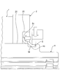
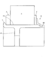
- FIG. 1 is a schematic configuration view of a rotor structure of a rotary electric machine showing an embodiment of the present invention.
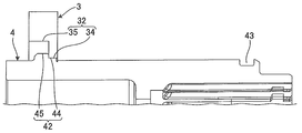
- FIG. 2 is an explanatory view showing the same manufacturing process of the rotor structure of the rotary electric machine.
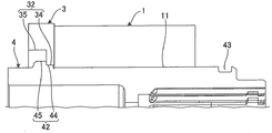
- FIG. 3 is an explanatory view showing the manufacturing process of the rotor structure of the rotary electric machine continued from FIG.
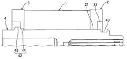
- FIG. 4 is an explanatory view showing the manufacturing process of the rotor structure of the rotary electric machine continued from FIG. 3;
- FIG. 1 is a schematic configuration view of a rotor structure of a rotary electric machine showing an embodiment of the present invention.
- FIG. 2 is an explanatory view showing the same manufacturing process of the rotor structure of the rotary electric machine.
- FIG. 3 is an
- FIG. 7 is an explanatory view showing the manufacturing process of the rotor structure of the rotary electric machine continued from FIG.
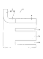
- FIG. 8 is a partial cross-sectional view of a crimp retainer used.
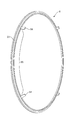
- FIG. 9 is a perspective view showing an example of a crimp retainer.
- FIG. 10 is a perspective view showing another example of the crimp retainer.
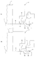
- FIG. 11 is an explanatory view showing the shapes (A) and (B) after caulking of the caulking retainer.
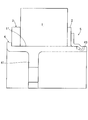
- FIG. 12 is a schematic configuration diagram of a rotor structure of a rotary electric machine showing a second embodiment of the present invention.
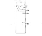
- FIG. 13 is a cross-sectional view of a crimp retainer.
- FIG. 14 is a cross-sectional view of the crimp retainer in a compressed state.
- FIG. 15 is a schematic configuration view of a rotor structure of a rotary electric machine showing one aspect in which a crimp retainer is elastically deformed
- FIG. 1 is a cross-sectional view showing an embodiment of a rotor structure of a rotating electrical machine to which the present invention is applied.
- the rotor structure of the rotating electrical machine includes a cylindrical core 1, disk-shaped end plates 2 and 3 disposed on both sides of the core 1, and a rotor for inserting and supporting the cores 1 and the end plates 2 and 3. It has a caulking retainer 5 which positions and fixes the shaft 4, the core 1 and the end plates 2, 3 on the rotor shaft 4.
- the rotor shaft 4 has a cylindrical shape, and is provided with a flange 41 extending in the circumferential direction on the inner peripheral portion of the cylindrical portion, and is fastened to a drive shaft (not shown) via the flange 41 and formed rotatably with the drive shaft.
- the outer diameter of the rotor shaft 4 is formed to substantially match the inner diameter of the core 1.
- a projection 42 for supporting the other end plate 3 is formed over the entire circumference on the outer peripheral portion on one side in the axial direction of the region for supporting the core 1 of the rotor shaft 4.
- a caulking groove 43 with which the caulking retainer 5 is engaged is formed over the entire circumference of the outer peripheral portion on the other side in the axial direction of the region supporting the core 1 of the rotor shaft 4.
- the caulking grooves 43 may be partially provided in the circumferential direction without being provided on the entire circumference.
- the outer peripheral portion of the rotor shaft 4 is smaller in diameter in the axial direction outer side (away from the core 1 supporting region) than the portion where the caulking groove 43 is disposed.
- the protrusion 42 is formed in a stepped shape including a small diameter portion 44 and a large diameter portion 45.
- the small diameter portion 44 protrudes radially outward from the outer peripheral portion of the rotor shaft 4 adjacent to the region supporting the core 1, and the large diameter portion 45 is continuous with the small diameter portion 44 (away from the core 1 supporting region)
- the rotor shaft 4 is formed to project radially outward from the outer peripheral portion of the rotor shaft 4.
- the core 1 is formed by, for example, forming a shaft insertion hole 11 in the central portion of a circular magnetic steel plate which is a magnetic body, laminating a large number of the magnetic steel plates, and integrating them by caulking or the like.
- the inner diameter portion of the other disk-shaped end plate 3 is a stepped hole 32 including a small diameter hole 34 fitted with the small diameter portion 44 of the projection 42 and a large diameter hole 35 facing the large diameter portion 45 of the projection 42. Is formed. Then, as shown in FIG. 2, in the other end plate 3, the small diameter hole 34 of the stepped hole 32 is engaged with the small diameter portion 44 of the stepped projection 42 of the rotor shaft 4, and the small diameter hole 34 and the large diameter hole The stepped portion between 35 and 35 is axially supported by the stepped portion between the large diameter portion 45 and the small diameter portion 44 of the stepped protrusion, and is supported by the protruding portion 42 of the rotor shaft 4.
- the core 1 which consists of a disk shaped laminated steel plate is fitted to the outer peripheral part of the rotor shaft 4, and is laminated
- An inner diameter portion of one disk-shaped end plate 2 is a stepped hole including a small diameter hole 21 disposed on the side contacting the core 1 and a large diameter hole 22 disposed on the side opposite to the core 1 side. Is formed. Then, as shown in FIG. 4, the small diameter hole 21 of the stepped hole is fitted to the outer peripheral portion of the rotor shaft 4 and one end plate 2 is stacked and arranged from the other side in the axial direction of the core 1, It is supported by the rotor shaft 4.
- the caulking retainer 5 includes a ring-shaped portion 51 having a disk shape whose cross section including an annular flange portion 52 and an annular sleeve portion 53 is L-shaped, and a sleeve portion 53. It is formed by the crimping piece 54 which protrudes in the axial direction more, and is crimped and deformed.
- the sleeve portion 53 and the caulking piece 54 are formed to fit on the outer periphery of the rotor shaft 4, and the sleeve portion 53 is positioned on the rotor shaft 4 in the radial direction by fitting on the rotor shaft 4.
- the ring-shaped portion 51 of the caulking retainer 5 has an L-shaped cross section formed by the flange portion 52 and the sleeve portion 53, so that the shape rigidity, that is, the bending rigidity with respect to a plane perpendicular to the axis is a circular shape by the sleeve portion 53.
- the rigidity is a shape secured by the flange portion 52, respectively.
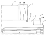
- the caulking retainer 5 is fitted to the rotor shaft 4 from the side of the caulking groove 43, and as shown in FIG. The stepped portions between the holes 22 are brought into contact. Then, a state in which a predetermined preload (preload) is applied to the end plate 3, the core 1 and the end plate 2 disposed between the projection retainer 42 and the protrusion 42 of the rotor shaft 4 by axially pressing from the caulking retainer 5 side Do.
- preload a predetermined preload
- the caulking pieces 54 of the caulking retainer 5 are caulked from the outer circumference into the caulking grooves 43 in the radially inward direction by caulking so as to fit into the caulking grooves 43 and to the rotor shaft 4. It is positioned axially with respect to it. And since the bending end of the caulking piece 54 of the caulking retainer 5 abuts against the wall surface of the bottom of the caulking groove 43 and the axial outward movement is blocked, the both end plates 2 and 3 and the core 1 are stretched. The rotor shaft 4 can be positioned and fixed while maintaining the applied preload.
- the crimped pieces 54 at the tip of the sleeve portion 53 are provided with slits 55 extending axially from the end at constant intervals in the circumferential direction. By absorbing the circumferential length, the radially inward bent end surely reaches the bottom of the caulking groove 43.
- the slits 55 described above may have a narrow width as shown in FIG.
- 9 and 10 show an example of the width and the number of the slits 55, and it is desirable to change and set the width and the number as needed.
- the core 1 has a structure in which, for example, hundreds of electromagnetic steel sheets are laminated in the axial direction
- the axial dimension in the laminated state changes for each laminated core 1.
- the axial position of the caulking retainer 5 changes in accordance with the error of the stacking dimension. Therefore, as shown in FIG. 6, the axial dimension of the crimped piece 54 is set so that the crimped piece 54 of the crimped retainer 5 straddles the crimped groove 43, as shown in FIG.
- the caulking piece 54 is engaged with the wall surface on the axially outer side of the caulking groove 43 as shown in FIG.
- the tip end of the groove 34 protrudes beyond the end of the caulking groove 43.
- the position of the caulking piece 54 of the caulking retainer 5 facing the caulking groove 43 moves axially outward, and further straddles the caulking groove 43 in the axial direction. It will be located.
- the caulking piece 54 is engaged with the axially outer wall surface of the caulking groove 43, and the end of the caulking piece 54 is further from the end of the caulking groove 43 than in FIG. It will be in the state where it overflowed.
- the crimped groove 43 is not in a state where the tip end of the crimped piece 54 protrudes beyond the axially outer end of the crimped groove 43 after the crimping process. It will be in the state engaged with the wall surface of the axial direction of this.
- caulking grooves 43 are formed in the outer peripheral portion in the axial direction outer side of either one end plate 2 in the circumferential direction. Then, it has a ring shape and is fitted to the rotor shaft 4 so as to cover the crimped groove 43 of the rotor shaft 4, and the axially outer portion is crimped from the outer peripheral side and fitted to the crimped groove 43 of the rotor shaft 4
- One end plate 2 is positioned in the axial direction by the axially inner end of the caulking retainer 5 engaged with the axially outer wall surface 43.
- the axially outer portion of the caulking retainer 5 which is positioned in the axial direction in contact with one end plate 2 is caulked from the outer peripheral side to fit in the caulking groove 43 of the rotor shaft 4 and axially outside the caulking groove 43 It has a configuration to be engaged with the wall surface. Therefore, the caulking retainer 5 engages with the axially outer wall surface of the caulking groove 43 so that the core 1 can be positioned without coming off in the axial direction, and the reaction acts to press one end plate 2 in the axial direction. Can be fixed to the rotor shaft 4 in a state in which the core 1 is given a predetermined preload.
- the caulking retainer 5 is axially inward from the axially outer end portion at a predetermined angular interval in the circumferential direction on the axially outer portion caulked from the outer peripheral side and fitted in the caulking groove 43 of the rotor shaft 4
- the slit 55 extends. That is, when the caulking piece 54 at the end of the sleeve portion 53 of the caulking retainer 5 is fitted into the caulking groove 43, the diameter of the bent end is reduced and the circumferential length is reduced, resulting in an extra circumferential length.
- the caulking pieces 54 at the tip of the sleeve portion 53 of the caulking retainer 5 have slits 55 extending axially from the end at constant intervals in the circumferential direction, the above-mentioned excess circumferential length is absorbed by the slits 55, It is possible to ensure that the radially inward bent end reaches the bottom of the crimping groove 43.
- the caulking retainer 5 is caulked from the outer peripheral side according to the axial position of one end plate 2 in contact with the axially inner end, and is fitted in the caulking groove 43 of the rotor shaft 4 and the caulking groove 43
- the axial position engaged with the axially outer wall surface is changed. That is, since the core 1 has a structure in which, for example, several hundred sheets of magnetic steel sheets are stacked in the axial direction, the axial dimension in the stacked state changes for each stacked core 1. And the axial direction position of the caulking retainer 5 changes with the error of this lamination dimension.
- the caulking retainer 5 has a ring-shaped flange 52 extending radially at the axially inner end, and contacts the one end plate 2 by the ring-shaped flange 52. That is, the ring-shaped portion 51 of the caulking retainer 5 has an L-shaped cross section formed by the flange portion 52 and the sleeve portion 53 so that the sleeve portion 53 has shape rigidity, that is, bending rigidity with respect to a plane perpendicular to the axis.
- the circular shape rigidity can be made into the shape ensured by the flange part 52, respectively.
- Second Embodiment 12 to 15 show a second embodiment of a rotor structure of a rotary electric machine to which the present invention is applied
- FIG. 12 is a cross-sectional view of the rotor structure of the rotary electric machine
- FIG. 13 is a cross-sectional view of a caulking retainer.
- a configuration in which the flange portion of the ring-shaped portion of the crimp retainer has a spring structure that acts in the axial direction is added to the first embodiment.
- the same units as those in the first embodiment are indicated by the same reference numerals, and the description thereof will be omitted or simplified.
- the caulking retainer 5 in the present embodiment is axially deformed by caulking deformation from the sleeve portion 53 and the ring-shaped portion 51 including the tapered flange portion 56 and the ring-shaped sleeve portion 53.
- the caulking piece 54 is formed.
- the caulking retainer 5 is formed of a high elastic material, for example, a high tensile strength steel sheets (generally called "high strength material").
- high strength material generally called "high strength material”.
- the other configuration is the same as that of the first embodiment.
- the caulking retainer 5 can be elastically deformed in the direction in which the taper angle becomes large by applying a compressive force in the axial direction. That is, as the dimension C in the state of not applying the axial compressive force shown in FIG. 13 is applied with the axial compressive force, the taper angle of the flange portion 56 is increased corresponding to the compressive force, and the final As shown in FIG. 14, the flange portion 56 can be elastically deformed to a dimension D in which the flange portion 56 is erected in the perpendicular direction.
- the sleeve portion 53 and the caulking piece 54 are formed to fit on the outer periphery of the rotor shaft 4, and the sleeve portion 53 is positioned on the rotor shaft 4 in the radial direction by fitting on the rotor shaft 4.
- the caulking retainer 5 is fitted to the rotor shaft 4 from the side of the caulking groove 43, and as shown in FIG. 12, the tip end of the flange portion 56 is in contact with the side surface of one end plate 2. Then, the sleeve portion 53 and the caulking piece 54 of the caulking retainer 5 are axially pressed from the caulking retainer 5 side, and the end plate 3, the core 1 and the end plate 2 are disposed between them and the projection 42 of the rotor shaft 4. Constant preload (preload). At this time, the flange portion 56 of the caulking retainer 5 is elastically deformed so as to increase the taper angle by the above-mentioned constant preload (preload).
- the caulking piece 54 of the caulking retainer 5 is crimped into the radially inward caulking groove 43 by caulking from the outer periphery, thereby being fitted into the caulking groove 43 and positioned in the axial direction with respect to the rotor shaft 4 .
- the bending end of the caulking piece 54 of the caulking retainer 5 abuts against the wall surface of the bottom of the caulking groove 43 and the axial outward movement is blocked, the both end plates 2 and 3 and the core 1 are stretched.
- the rotor shaft 4 can be positioned and fixed while maintaining the applied preload.
- FIG. 15 shows a state in which the position of one end plate 2 is changed to the side of the caulking retainer 5 due to the error of the stacking dimension.
- the amount of elastic deformation of the flange portion 56 of the caulking retainer 5 changes in accordance with the error of the stacking dimension.
- the caulking retainer 5 has a ring-shaped flange portion 56 extending radially at the axially inner end, and the flange portion 56 is formed to be tapered so that the tip thereof contacts the end plate 2 Depending on the axial position of one end plate 2 in contact with the axially inner end, the tapered inclination angle is changed. That is, since the core 1 has a structure in which, for example, several hundred sheets of magnetic steel sheets are stacked in the axial direction, the axial dimension in the stacked state changes for each stacked core 1. However, the amount of elastic deformation of the flange portion 56 of the caulking retainer 5 changes with the error of the stacking dimension.
Landscapes
- Engineering & Computer Science (AREA)
- Power Engineering (AREA)
- Manufacturing & Machinery (AREA)
- Iron Core Of Rotating Electric Machines (AREA)
- Manufacture Of Motors, Generators (AREA)
Abstract
Description
図1は本発明を適用した回転電機のロータ構造の一実施形態を示す断面図である。図1において、回転電機のロータ構造は、円筒状のコア1、コア1の両側に配置した円盤状のエンドプレート2,3、それらのコア1およびエンドプレート2,3を挿通して支持するロータシャフト4、コア1およびエンドプレート2,3をロータシャフト4上に位置決めして固定するカシメリテーナ5、を備える。
図12~図15は本発明を適用した回転電機のロータ構造の第2実施形態を示し、図12は回転電機のロータ構造の断面図、図13はカシメリテーナの断面図である。本実施形態においては、カシメリテーナのリング状部分のフランジ部を軸方向に作用するばね構造とした構成を第1実施形態に追加したものである。なお、第1実施形態と同一装置には同一符号を付してその説明を省略ないし簡略化する。
Claims (7)
- ロータシャフト外周に円盤状の複数の磁性鋼板を積層したコアとコアの軸方向両側に配置した円盤状のエンドプレートとを支持して備える回転電機のロータ構造であって、
前記ロータシャフトは、いずれか一方のエンドプレートの軸方向外側の外周部に周方向に形成したカシメ溝を備え、
前記一方のエンドプレートは、リング状をなし、ロータシャフトのカシメ溝を覆ってロータシャフトに嵌合され、軸方向外側部分が外周側からカシメられてロータシャフトのカシメ溝に嵌合され且つカシメ溝の軸方向外側の壁面に係合する、カシメリテーナの軸方向内側端により軸方向に位置決めされる、
回転電機のロータ構造。 - 請求項1に記載の回転電機のロータ構造において、
前記カシメリテーナは、外周側からカシメられてロータシャフトのカシメ溝に嵌合される軸方向外側部分に、周方向所定角度間隔をおいて軸方向外端部分から軸方向内側に延びるスリットを備える、
回転電機のロータ構造。 - 請求項1または請求項2に記載の回転電機のロータ構造において、
前記カシメリテーナは、軸方向内側端に接触する一方のエンドプレートの軸方向位置に応じて、外周側からカシメられてロータシャフトのカシメ溝に嵌合し且つカシメ溝の軸方向外側の壁面に係合する軸方向位置が変化される、
回転電機のロータ構造。 - 請求項1から請求項3のいずれか1項に記載の回転電機のロータ構造において、
前記カシメリテーナは、軸方向内側端に半径方向に延びるリング状のフランジ部を備え、リング状フランジ部により一方のエンドプレートに接触する、
回転電機のロータ構造。 - 請求項1または請求項2に記載の回転電機のロータ構造において、
前記カシメリテーナは、軸方向内側端に半径方向に延びるリング状のフランジ部を備え、
前記フランジ部は、その先端が一方のエンドプレートに接触するようテーパ状に傾斜させて形成され、軸方向内側端に接触する一方のエンドプレートの軸方向位置に応じて、テーパ状の傾斜角度が変化される、
回転電機のロータ構造。 - 請求項1から請求項4のいずれか1項に記載の回転電機のロータ構造において、
前記カシメ溝は、前記ロータシャフトの外周部の全周にわたって形成される、
回転電機のロータ構造。 - ロータシャフト外周に円盤状の複数の磁性鋼板を積層して形成されたコアとコアの軸方向両側に配置された円盤状のエンドプレートとを支持して備える回転電機のロータ構造の製造方法であって、
前記ロータシャフトは、いずれか一方のエンドプレートの軸方向外側の外周部に周方向に形成したカシメ溝を備え、
リング状のカシメリテーナを、ロータシャフトのカシメ溝を覆ってロータシャフトに嵌合させ、カシメリテーナの軸方向内側端を前記一方のエンドプレートに予圧を加えて当接させ、
次いで、カシメリテーナの軸方向外側部分を外周側からカシメてロータシャフトのカシメ溝に嵌合させ且つカシメ溝の軸方向外側の壁面に係合させることにより、前記一方のエンドプレートを軸方向に位置決めする、
回転電機のロータ構造の製造方法。
Priority Applications (3)
| Application Number | Priority Date | Filing Date | Title |
|---|---|---|---|
| CN201280004439.0A CN103283122B (zh) | 2011-03-02 | 2012-03-01 | 旋转电机的转子构造及其制造方法 |
| EP12752558.2A EP2683060B1 (en) | 2011-03-02 | 2012-03-01 | Rotor structure of rotating electric machine and manufacturing method thereof |
| US14/002,012 US9318924B2 (en) | 2011-03-02 | 2012-03-01 | Rotor mechanism of rotating electrical machine and method of manufacturing same |
Applications Claiming Priority (4)
| Application Number | Priority Date | Filing Date | Title |
|---|---|---|---|
| JP2011-045287 | 2011-03-02 | ||
| JP2011045287 | 2011-03-02 | ||
| JP2012043774A JP5880136B2 (ja) | 2011-03-02 | 2012-02-29 | 回転電機のロータ構造およびその製造方法 |
| JP2012-043774 | 2012-02-29 |
Publications (1)
| Publication Number | Publication Date |
|---|---|
| WO2012118157A1 true WO2012118157A1 (ja) | 2012-09-07 |
Family
ID=46758083
Family Applications (1)
| Application Number | Title | Priority Date | Filing Date |
|---|---|---|---|
| PCT/JP2012/055267 Ceased WO2012118157A1 (ja) | 2011-03-02 | 2012-03-01 | 回転電機のロータ構造およびその製造方法 |
Country Status (5)
| Country | Link |
|---|---|
| US (1) | US9318924B2 (ja) |
| EP (1) | EP2683060B1 (ja) |
| JP (1) | JP5880136B2 (ja) |
| CN (1) | CN103283122B (ja) |
| WO (1) | WO2012118157A1 (ja) |
Cited By (1)
| Publication number | Priority date | Publication date | Assignee | Title |
|---|---|---|---|---|
| CN114915062A (zh) * | 2022-06-10 | 2022-08-16 | 珠海格力电器股份有限公司 | 转子组件及电机 |
Families Citing this family (9)
| Publication number | Priority date | Publication date | Assignee | Title |
|---|---|---|---|---|
| JP5796376B2 (ja) * | 2011-07-05 | 2015-10-21 | 日産自動車株式会社 | 電動モータのロータ |
| JP2015220950A (ja) * | 2014-05-21 | 2015-12-07 | 富士電機株式会社 | 回転電機 |
| JP2019009898A (ja) * | 2017-06-23 | 2019-01-17 | アイシン精機株式会社 | モータ |
| JP7053381B2 (ja) * | 2018-06-13 | 2022-04-12 | Ntn株式会社 | ロータユニット、電動モータ及び電動アクチュエータ |
| KR102649706B1 (ko) * | 2019-04-12 | 2024-03-19 | 엘지마그나 이파워트레인 주식회사 | 모터 |
| US11552517B2 (en) * | 2020-05-08 | 2023-01-10 | Schaeffler Technologies AG & Co. KG | Self-retaining compressional diaphragm spring |
| DE102020116612A1 (de) | 2020-06-24 | 2021-12-30 | Schaeffler Technologies AG & Co. KG | Rotor und Radialflussmaschine |
| DE102020210497A1 (de) | 2020-08-19 | 2022-02-24 | Zf Friedrichshafen Ag | Rotor einer permanenterregten elektrischen Maschine |
| DE102020132470A1 (de) | 2020-12-07 | 2022-06-09 | Schaeffler Technologies AG & Co. KG | Axiale Fixierung einer Wellenkomponente einer elektrischen Maschine |
Citations (2)
| Publication number | Priority date | Publication date | Assignee | Title |
|---|---|---|---|---|
| JP2006187063A (ja) | 2004-12-27 | 2006-07-13 | Nissan Motor Co Ltd | ロータ構造 |
| JP2007124752A (ja) * | 2005-10-26 | 2007-05-17 | Toyota Motor Corp | ロータシャフトおよびロータシャフトの製造方法 |
Family Cites Families (16)
| Publication number | Priority date | Publication date | Assignee | Title |
|---|---|---|---|---|
| FR2707813B1 (fr) * | 1993-07-16 | 2000-12-29 | Mitsuba Electric Mfg C | Rotor de magnéto-générateur et procédé pour sa fabrication. |
| JPH07212912A (ja) | 1994-01-20 | 1995-08-11 | Fuji Electric Co Ltd | 電気自動車の電気制動制御方法 |
| JP2004048925A (ja) * | 2002-07-12 | 2004-02-12 | Toyota Motor Corp | ステータの固定方法及び固定構造並びにロータの固定方法及び固定構造 |
| KR100469463B1 (ko) * | 2002-09-10 | 2005-02-02 | 엘지전자 주식회사 | 왕복동식 압축기의 고정자 결합구조 |
| JP2004156716A (ja) * | 2002-11-07 | 2004-06-03 | Kayaba Ind Co Ltd | 軸部材に被固定部材を固定する固定方法および固定部の構造 |
| EP1599928B1 (de) * | 2003-02-26 | 2013-08-28 | Robert Bosch Gmbh | Elektrische maschine mit einem permanentmagnet |
| EP1596487A1 (de) * | 2004-05-10 | 2005-11-16 | Siemens Aktiengesellschaft | Rotor und Verfahren zur Herstellung eines Rotors für einen elektromotorischen Kraftfahrzeug-Stellantrieb |
| JP2006067668A (ja) | 2004-08-25 | 2006-03-09 | Nissan Motor Co Ltd | 電動機制御装置 |
| US7358637B2 (en) * | 2005-11-04 | 2008-04-15 | Canopy Technologies, Llc | Method of compressing lamination stacks for permanent magnet rotor |
| JP2008109804A (ja) * | 2006-10-26 | 2008-05-08 | Toyota Motor Corp | 回転電機 |
| JP2008193772A (ja) | 2007-02-01 | 2008-08-21 | Toyota Motor Corp | 電気自動車の制御装置および制御方法、ならびに電気自動車 |
| JP4502039B2 (ja) * | 2008-04-15 | 2010-07-14 | トヨタ自動車株式会社 | 電動機回転子製造方法、及び、電動機回転子 |
| US7812495B2 (en) * | 2008-05-16 | 2010-10-12 | Honeywell International Inc. | Sleeve in end rings for permanent magnet rotor |
| JP2010148250A (ja) | 2008-12-19 | 2010-07-01 | Mitsubishi Motors Corp | 電気自動車の制御装置 |
| US8970085B2 (en) * | 2011-04-01 | 2015-03-03 | Denso Corporation | Rotor for electric rotating machine and method of manufacturing the same |
| US9130434B2 (en) * | 2012-02-01 | 2015-09-08 | Remy Technologies, Llc | Induction rotor end ring support device |
-
2012
- 2012-02-29 JP JP2012043774A patent/JP5880136B2/ja not_active Expired - Fee Related
- 2012-03-01 US US14/002,012 patent/US9318924B2/en not_active Expired - Fee Related
- 2012-03-01 EP EP12752558.2A patent/EP2683060B1/en not_active Not-in-force
- 2012-03-01 WO PCT/JP2012/055267 patent/WO2012118157A1/ja not_active Ceased
- 2012-03-01 CN CN201280004439.0A patent/CN103283122B/zh not_active Expired - Fee Related
Patent Citations (2)
| Publication number | Priority date | Publication date | Assignee | Title |
|---|---|---|---|---|
| JP2006187063A (ja) | 2004-12-27 | 2006-07-13 | Nissan Motor Co Ltd | ロータ構造 |
| JP2007124752A (ja) * | 2005-10-26 | 2007-05-17 | Toyota Motor Corp | ロータシャフトおよびロータシャフトの製造方法 |
Non-Patent Citations (1)
| Title |
|---|
| See also references of EP2683060A4 * |
Cited By (1)
| Publication number | Priority date | Publication date | Assignee | Title |
|---|---|---|---|---|
| CN114915062A (zh) * | 2022-06-10 | 2022-08-16 | 珠海格力电器股份有限公司 | 转子组件及电机 |
Also Published As
| Publication number | Publication date |
|---|---|
| US20130334926A1 (en) | 2013-12-19 |
| EP2683060B1 (en) | 2017-05-10 |
| US9318924B2 (en) | 2016-04-19 |
| EP2683060A4 (en) | 2016-05-11 |
| CN103283122B (zh) | 2016-02-17 |
| JP5880136B2 (ja) | 2016-03-08 |
| CN103283122A (zh) | 2013-09-04 |
| JP2012196125A (ja) | 2012-10-11 |
| EP2683060A1 (en) | 2014-01-08 |
Similar Documents
| Publication | Publication Date | Title |
|---|---|---|
| WO2012118157A1 (ja) | 回転電機のロータ構造およびその製造方法 | |
| JP6416786B2 (ja) | 減衰カラーを備える回転機械 | |
| WO2011125183A1 (ja) | ロータ及びその製造方法 | |
| JP2019004568A (ja) | 回転電機のステータ | |
| JP6221032B2 (ja) | モータ | |
| JP2014005897A (ja) | 転がり軸受及びその製造方法 | |
| WO2018179736A1 (ja) | ロータ及びロータを備えたモータ | |
| JP2014003881A (ja) | 回転電機のステータ | |
| CN102948044A (zh) | 电机 | |
| JP2007259583A (ja) | モータのエンドプレート構造 | |
| WO2020054057A1 (ja) | 回転電機 | |
| WO2015129163A1 (ja) | ボールねじ装置 | |
| JP2008514182A (ja) | 電気機器 | |
| US20240369099A1 (en) | Axial rolling bearing unit with rolling bodies, which are arranged between annular axial bearing washers, and a functionally integrated bearing cage | |
| JP7479261B2 (ja) | モータ | |
| JP2011078219A (ja) | 回転電機用固定子及びその製造方法 | |
| JP2010063205A (ja) | ロータ及びロータの製造方法 | |
| JP2012180860A (ja) | 軸受の固定構造 | |
| JP2014183630A (ja) | 回転電機のステータ、及びその製造方法 | |
| JP5225700B2 (ja) | 転がり軸受ユニット | |
| JP5923290B2 (ja) | ロータコアの固定方法 | |
| JP2022041334A (ja) | センサ固定構造及び方法 | |
| JP6001504B2 (ja) | ロータ体 | |
| JP4639469B2 (ja) | モータ及びそのモータの分割コアの組立方法 | |
| JP2014014234A (ja) | 回転電機のステータ |
Legal Events
| Date | Code | Title | Description |
|---|---|---|---|
| WWE | Wipo information: entry into national phase |
Ref document number: 201280004439.0 Country of ref document: CN |
|
| 121 | Ep: the epo has been informed by wipo that ep was designated in this application |
Ref document number: 12752558 Country of ref document: EP Kind code of ref document: A1 |
|
| REEP | Request for entry into the european phase |
Ref document number: 2012752558 Country of ref document: EP |
|
| WWE | Wipo information: entry into national phase |
Ref document number: 2012752558 Country of ref document: EP |
|
| WWE | Wipo information: entry into national phase |
Ref document number: 14002012 Country of ref document: US |
|
| NENP | Non-entry into the national phase |
Ref country code: DE |